EP1255426A1 - High temperature EUV source nozzle - Google Patents
High temperature EUV source nozzle Download PDFInfo
- Publication number
- EP1255426A1 EP1255426A1 EP02009576A EP02009576A EP1255426A1 EP 1255426 A1 EP1255426 A1 EP 1255426A1 EP 02009576 A EP02009576 A EP 02009576A EP 02009576 A EP02009576 A EP 02009576A EP 1255426 A1 EP1255426 A1 EP 1255426A1
- Authority
- EP
- European Patent Office
- Prior art keywords
- nozzle
- target material
- delivery tube
- source
- exit end
- Prior art date
- Legal status (The legal status is an assumption and is not a legal conclusion. Google has not performed a legal analysis and makes no representation as to the accuracy of the status listed.)
- Granted
Links
- 239000013077 target material Substances 0.000 claims abstract description 68
- 239000007788 liquid Substances 0.000 claims abstract description 40
- 230000005855 radiation Effects 0.000 claims abstract description 30
- 239000000463 material Substances 0.000 claims abstract description 9
- 239000010935 stainless steel Substances 0.000 claims abstract description 5
- 229910001220 stainless steel Inorganic materials 0.000 claims abstract description 5
- 239000007921 spray Substances 0.000 claims description 19
- 238000000034 method Methods 0.000 claims description 10
- OKTJSMMVPCPJKN-UHFFFAOYSA-N Carbon Chemical compound [C] OKTJSMMVPCPJKN-UHFFFAOYSA-N 0.000 claims description 7
- 239000010439 graphite Substances 0.000 claims description 7
- 229910002804 graphite Inorganic materials 0.000 claims description 7
- 239000002245 particle Substances 0.000 claims description 3
- 239000007787 solid Substances 0.000 claims description 2
- 239000011819 refractory material Substances 0.000 claims 2
- 238000010438 heat treatment Methods 0.000 abstract description 6
- 238000002955 isolation Methods 0.000 abstract description 5
- 239000007789 gas Substances 0.000 description 12
- 238000000206 photolithography Methods 0.000 description 6
- 238000009833 condensation Methods 0.000 description 4
- 230000005494 condensation Effects 0.000 description 4
- PXHVJJICTQNCMI-UHFFFAOYSA-N Nickel Chemical compound [Ni] PXHVJJICTQNCMI-UHFFFAOYSA-N 0.000 description 2
- 238000004891 communication Methods 0.000 description 2
- 230000000694 effects Effects 0.000 description 2
- 239000012811 non-conductive material Substances 0.000 description 2
- 230000001902 propagating effect Effects 0.000 description 2
- 238000004544 sputter deposition Methods 0.000 description 2
- 229910052724 xenon Inorganic materials 0.000 description 2
- FHNFHKCVQCLJFQ-UHFFFAOYSA-N xenon atom Chemical compound [Xe] FHNFHKCVQCLJFQ-UHFFFAOYSA-N 0.000 description 2
- 230000002411 adverse Effects 0.000 description 1
- 230000015572 biosynthetic process Effects 0.000 description 1
- 239000000919 ceramic Substances 0.000 description 1
- 238000006243 chemical reaction Methods 0.000 description 1
- 238000001816 cooling Methods 0.000 description 1
- 230000007423 decrease Effects 0.000 description 1
- 230000003628 erosive effect Effects 0.000 description 1
- 238000001900 extreme ultraviolet lithography Methods 0.000 description 1
- 239000012530 fluid Substances 0.000 description 1
- 229910052743 krypton Inorganic materials 0.000 description 1
- DNNSSWSSYDEUBZ-UHFFFAOYSA-N krypton atom Chemical compound [Kr] DNNSSWSSYDEUBZ-UHFFFAOYSA-N 0.000 description 1
- 238000004519 manufacturing process Methods 0.000 description 1
- 238000004377 microelectronic Methods 0.000 description 1
- 238000012986 modification Methods 0.000 description 1
- 230000004048 modification Effects 0.000 description 1
- 229910052759 nickel Inorganic materials 0.000 description 1
- 230000003287 optical effect Effects 0.000 description 1
- 239000000758 substrate Substances 0.000 description 1
- 239000002470 thermal conductor Substances 0.000 description 1
- 238000009834 vaporization Methods 0.000 description 1
- 230000008016 vaporization Effects 0.000 description 1
- 238000010792 warming Methods 0.000 description 1
Images
Classifications
-
- H—ELECTRICITY
- H05—ELECTRIC TECHNIQUES NOT OTHERWISE PROVIDED FOR
- H05G—X-RAY TECHNIQUE
- H05G2/00—Apparatus or processes specially adapted for producing X-rays, not involving X-ray tubes, e.g. involving generation of a plasma
- H05G2/001—Production of X-ray radiation generated from plasma
- H05G2/002—Supply of the plasma generating material
- H05G2/0023—Constructional details of the ejection system
Definitions
- This invention relates generally to a nozzle for an extreme ultraviolet (EUV) lithography source and, more particularly, to a nozzle for an EUV source that employs a target delivery tube within the nozzle to thermally isolate the target material from the heat generated by the plasma.
- EUV extreme ultraviolet
- Microelectronic integrated circuits are typically patterned on a substrate by a photolithography process that is well known to those skilled in the art, where the circuit elements are defined by a light beam propagating through a mask.
- the circuit elements become smaller and more closely spaced together.
- the resolution of the photolithography process increases as the wavelength of the light source decreases to allow smaller integrated circuit elements to be defined.
- the current state of the art for photolithography light sources generate light in the extreme ultraviolet (EUV) or soft X-ray wavelengths (13.4nm).
- EUV radiation sources are known in the art to generate EUV radiation.
- One of the most popular EUV radiation sources is a laser-plasma, gas condensation source that uses a gas, typically Xenon, as a laser plasma target material.
- gases such as Krypton, and combinations of gases, are also known for the laser target material.
- the gas is forced through a nozzle, and as the gas expands, it condenses and converts to a liquid spray.
- the liquid spray is illuminated by a high-power laser beam, typically from an Nd:YAG laser, that heats the liquid droplets to produce a high temperature plasma which radiates the EUV radiation.
- U.S. Patent No. 5,577,092 issued to Kubiak discloses an EUV radiation source of this type.
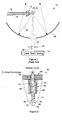
- Figure 1 is a plan view of a known EUV radiation source 10 including a nozzle 12 and a laser beam source 14.
- a gas 16 flows through a neck portion 18 of the nozzle 12 from a gas source (not shown). The gas 16 is accelerated through a narrowed throat portion and is expelled through an exit collimator of the nozzle 12 as a jet spray 26 of liquid droplets.
- a laser beam 30 from the source 14 is focused by focusing optics 32 on the liquid droplets. The energy of the laser beam 30 generates a plasma 34 that radiates EUV radiation 36.
- the nozzle 12 is designed so that it will stand up to the heat and rigors of the plasma generation process.
- the EUV radiation 36 is collected by collector optics 38 and is directed to the circuit (not shown) being patterned.
- the collector optics 38 can have any suitable shape for the purposes of collecting and directing the radiation 36. In this design, the laser beam 30 propagates through an opening 40 in the collector optics 38.
- U.S. Patent application Serial No. (Attorney Docket No. 11-1119), filed August 23, 2000, titled "Liquid Sprays as the Target for a Laser-Plasma Extreme Ultraviolet Light Source,” discloses a laser-plasma, extreme ultraviolet light source for a photolithography system that employs a liquid spray as a target material for generating the laser plasma.
- the EUV source forces a liquid, preferably Xenon, through the nozzle, instead of forcing a gas through the nozzle.
- the geometry of the nozzle and the pressure of the liquid propagating through the nozzle atomizes the liquid to form a dense spray of liquid droplets. Because the droplets are formed from a liquid, they are larger in size, and are more conducive to generating the EUV radiation.
- the plasma generation area is typically about 2mm away from the nozzle exit, and is generating heat at about 200,000°K. Because the EUV radiation source nozzle is positioned so close to the plasma generation area, the heat from the plasma heats the nozzle and thus the target material therein.
- the nozzles are typically subjected to thermal inputs up to 10 kW/cm2. Warming the target material at the expansion aperture of the nozzle leads to reduced target production and to the formation of EUV absorbing vapors. Particularly, heating of the nozzle to such high temperatures causes some of the liquid target material to vaporize reducing the liquid density of the target.
- particles from the plasma generation process cause a sputtering effect on the nozzle which adversely affects the EUV generation. It is known in the art to make the nozzle out of graphite to reduce the sputtering effects, although other materials may be used for better erosion resistance. However, graphite is a good thermal conductor which enhances heating of the cold target material within the nozzle.
- a nozzle for a laser-plasma EUV radiation source that provides thermal isolation between the nozzle body and the target material traveling therethrough to enhance the EUV radiation generation. It is therefore an object of the present invention to provide such an EUV radiation source nozzle.
- a nozzle for a laser-plasma EUV radiation source that provides thermal isolation between the nozzle body and the target material flowing therethrough.
- a separate target material delivery tube protrudes through the nozzle body with limited tube/nozzle surface contact such that proper tube/nozzle alignment is achieved while providing thermal isolation.
- the delivery tube is made of a material having low thermal conductivity, such as stainless steel, so that heating of the nozzle body from the plasma does not heat the liquid target material being delivered through the delivery tube.
- the delivery tube has an expansion aperture positioned behind an exit collimator of the nozzle body. The expansion aperture has a smaller diameter than the known exit collimators to deliver less material to the plasma generation area.
- Figure 1 is a plan view of a known laser-plasma, gas condensation, extreme ultraviolet light source.
- Figure 2 is a cross-sectional view of a nozzle for a laser-plasma, extreme ultraviolet radiation source employing a target material delivery tube, according to an embodiment of the present invention.
- FIG. 2 is a cross-sectional view of a nozzle 46 for an EUV source, according to the invention, and is applicable to replace the known nozzle 12 discussed above.
- the nozzle 46 includes a graphite body portion 48 having a size and shape suitable for the purposes described herein.
- the nozzle 46 includes a cylindrical exit collimator 50 through which the liquid target material exits the nozzle 46 under suitable pressure.
- the collimator 50 collimates the liquid spray so that it is directed towards the plasma generation area.
- a heat exchanger 54 is threaded into a threaded opening 56 in the body portion 48.
- the heat exchanger 54 includes a base portion 58 and stem portion 60 that is threaded within the threaded opening 56.
- the heat exchanger 54 provides cooling for the body portion 48, and further provides support for the nozzle 46.
- a bore 62 extends through the heat exchanger 54, and is in communication with a narrowed bore 64 in the body portion 48.
- the bore 64 is in fluid communication with the exit collimator 50, and forms a shoulder 70 therebetween.
- an elongated target material delivery tube 72 extends through the bores 62 and 64 and abuts against the shoulder 70, as shown.
- the tube 72 includes a wide portion 74 and a narrow end portion 76.
- the tube 72 is positioned to provide a gap between the delivery tube 72 and the heat exchanger 54, and a gap between the delivery tube 72 and the internal walls of the body portion 48 within the bore 64.
- the delivery tube 72 includes an expansion orifice 80, or an array of orifices, at the end of the narrowed portion 76 so that the orifice 80 is positioned proximate to the shoulder 70.
- the liquid target material is delivered from a suitable target source (not shown) through the delivery tube 72 and enters the exit collimator 50 under pressure.
- the delivery tube 72 provides thermal isolation from the heated graphite body portion 48 during plasma generation. Additionally, the gap between the delivery tube 72 and the body portion 48 is at low pressure because the process occurs under vacuum pressure, and serves to further insulate the cold target material within the delivery tube 72 from the heated body portion 48.
- the cold liquid target material is delivered at the desired operating pressure and temperature to the collimator 50 across which it undergoes supersonic expansion to yield particles of either solid or liquid target material.
- the diameter of the orifice 80 can be about 50 microns in one embodiment so that it provides the desirable size liquid droplets. Additionally, the delivery tube 72 provides structural integrity to the nozzle 46 so that the size of the body portion 48 can be minimized.
- the delivery tube 72 is made of a suitable stainless steel. However, this is the way of a non-limiting example in that other materials can be used, preferably thermally non-conductive materials, such as nickel and ceramic. Although it is desirable that the delivery tube 72 be made of a thermally non-conductive material, because of the gap, the contact area between the tubes 72 and the body portion 48 is minimal so that even thermally conductive delivery tubes will provide a reduced heating of the cold target material.
Landscapes
- Physics & Mathematics (AREA)
- Engineering & Computer Science (AREA)
- Optics & Photonics (AREA)
- Plasma & Fusion (AREA)
- X-Ray Techniques (AREA)
- Exposure Of Semiconductors, Excluding Electron Or Ion Beam Exposure (AREA)
- Exposure And Positioning Against Photoresist Photosensitive Materials (AREA)
Abstract
Description
- This invention relates generally to a nozzle for an extreme ultraviolet (EUV) lithography source and, more particularly, to a nozzle for an EUV source that employs a target delivery tube within the nozzle to thermally isolate the target material from the heat generated by the plasma.
- Microelectronic integrated circuits are typically patterned on a substrate by a photolithography process that is well known to those skilled in the art, where the circuit elements are defined by a light beam propagating through a mask. As the state of the art of the photolithography process and integrated circuit architecture becomes more developed, the circuit elements become smaller and more closely spaced together. As the circuit elements become smaller, it is necessary to employ photolithography light sources that generate light beams having shorter wavelengths and higher frequencies. In other words, the resolution of the photolithography process increases as the wavelength of the light source decreases to allow smaller integrated circuit elements to be defined. The current state of the art for photolithography light sources generate light in the extreme ultraviolet (EUV) or soft X-ray wavelengths (13.4nm).
- Different devices are known in the art to generate EUV radiation. One of the most popular EUV radiation sources is a laser-plasma, gas condensation source that uses a gas, typically Xenon, as a laser plasma target material. Other gases, such as Krypton, and combinations of gases, are also known for the laser target material. The gas is forced through a nozzle, and as the gas expands, it condenses and converts to a liquid spray. The liquid spray is illuminated by a high-power laser beam, typically from an Nd:YAG laser, that heats the liquid droplets to produce a high temperature plasma which radiates the EUV radiation. U.S. Patent No. 5,577,092 issued to Kubiak discloses an EUV radiation source of this type.
- Figure 1 is a plan view of a known EUV
radiation source 10 including anozzle 12 and alaser beam source 14. Agas 16 flows through aneck portion 18 of thenozzle 12 from a gas source (not shown). Thegas 16 is accelerated through a narrowed throat portion and is expelled through an exit collimator of thenozzle 12 as ajet spray 26 of liquid droplets. Alaser beam 30 from thesource 14 is focused by focusingoptics 32 on the liquid droplets. The energy of thelaser beam 30 generates aplasma 34 that radiatesEUV radiation 36. Thenozzle 12 is designed so that it will stand up to the heat and rigors of the plasma generation process. TheEUV radiation 36 is collected bycollector optics 38 and is directed to the circuit (not shown) being patterned. Thecollector optics 38 can have any suitable shape for the purposes of collecting and directing theradiation 36. In this design, thelaser beam 30 propagates through an opening 40 in thecollector optics 38. - It has been shown to be difficult to produce a spray having large enough droplets of liquid to achieve the desired efficiency of conversion of the laser radiation to the EUV radiation. Because the liquid droplets have too small a diameter, and thus not enough mass, the
laser beam 30 causes some of the droplets to break-up before they are heated to a sufficient temperature to generate theEUV radiation 36. Maximum diameters of droplets generated by a gas condensation EUV source is on the order of 0.33 microns. However, droplet sizes of about 1 micron in diameter would be desirable for generating the EUV radiation. Additionally, the large degree of expansion required to maximize the condensation process produces a diffuse jet of liquid, and is inconsistent with the optical requirement of a small plasma size. - To overcome the problem of having sufficiently large enough liquid droplets as the plasma target, U.S. Patent application Serial No. (Attorney Docket No. 11-1119), filed August 23, 2000, titled "Liquid Sprays as the Target for a Laser-Plasma Extreme Ultraviolet Light Source," discloses a laser-plasma, extreme ultraviolet light source for a photolithography system that employs a liquid spray as a target material for generating the laser plasma. In this design, the EUV source forces a liquid, preferably Xenon, through the nozzle, instead of forcing a gas through the nozzle. The geometry of the nozzle and the pressure of the liquid propagating through the nozzle atomizes the liquid to form a dense spray of liquid droplets. Because the droplets are formed from a liquid, they are larger in size, and are more conducive to generating the EUV radiation.
- Another problem exists in the known EUV sources that causes some of the liquid target material to vaporize prior to being energized by the laser. The plasma generation area is typically about 2mm away from the nozzle exit, and is generating heat at about 200,000°K. Because the EUV radiation source nozzle is positioned so close to the plasma generation area, the heat from the plasma heats the nozzle and thus the target material therein. The nozzles are typically subjected to thermal inputs up to 10 kW/cm2. Warming the target material at the expansion aperture of the nozzle leads to reduced target production and to the formation of EUV absorbing vapors. Particularly, heating of the nozzle to such high temperatures causes some of the liquid target material to vaporize reducing the liquid density of the target. Further, particles from the plasma generation process cause a sputtering effect on the nozzle which adversely affects the EUV generation. It is known in the art to make the nozzle out of graphite to reduce the sputtering effects, although other materials may be used for better erosion resistance. However, graphite is a good thermal conductor which enhances heating of the cold target material within the nozzle.
- What is needed is a nozzle for a laser-plasma EUV radiation source that provides thermal isolation between the nozzle body and the target material traveling therethrough to enhance the EUV radiation generation. It is therefore an object of the present invention to provide such an EUV radiation source nozzle.
- In accordance with the teachings of the present invention, a nozzle for a laser-plasma EUV radiation source is disclosed that provides thermal isolation between the nozzle body and the target material flowing therethrough. A separate target material delivery tube protrudes through the nozzle body with limited tube/nozzle surface contact such that proper tube/nozzle alignment is achieved while providing thermal isolation. In one embodiment, the delivery tube is made of a material having low thermal conductivity, such as stainless steel, so that heating of the nozzle body from the plasma does not heat the liquid target material being delivered through the delivery tube. The delivery tube has an expansion aperture positioned behind an exit collimator of the nozzle body. The expansion aperture has a smaller diameter than the known exit collimators to deliver less material to the plasma generation area.
- Additional objects, advantages and features of the present invention will become apparent to those skilled in the art from the following discussion and the accompanying drawings and claims.
- Figure 1 is a plan view of a known laser-plasma, gas condensation, extreme ultraviolet light source; and
- Figure 2 is a cross-sectional view of a nozzle for a laser-plasma, extreme ultraviolet radiation source employing a target material delivery tube, according to an embodiment of the present invention.
- The following discussion of the preferred embodiments directed to a nozzle for an EUV radiation source is merely exemplary in nature, and is in no way intended to limit the invention or its applications or uses.
- Figure 2 is a cross-sectional view of a
nozzle 46 for an EUV source, according to the invention, and is applicable to replace the knownnozzle 12 discussed above. Thenozzle 46 includes agraphite body portion 48 having a size and shape suitable for the purposes described herein. Thenozzle 46 includes acylindrical exit collimator 50 through which the liquid target material exits thenozzle 46 under suitable pressure. Thecollimator 50 collimates the liquid spray so that it is directed towards the plasma generation area. Aheat exchanger 54 is threaded into a threadedopening 56 in thebody portion 48. Theheat exchanger 54 includes abase portion 58 andstem portion 60 that is threaded within the threadedopening 56. Theheat exchanger 54 provides cooling for thebody portion 48, and further provides support for thenozzle 46. Abore 62 extends through theheat exchanger 54, and is in communication with anarrowed bore 64 in thebody portion 48. Thebore 64 is in fluid communication with theexit collimator 50, and forms ashoulder 70 therebetween. - In the known nozzles for EUV sources, the target material would flow through the
bores nozzle 46 through thecollimator 50. However, heating of thegraphite body portion 48 from the plasma generation would affect the liquid target within thebody portion 48, causing some vaporization and target loss. According to the present invention, an elongated targetmaterial delivery tube 72 extends through thebores shoulder 70, as shown. Thetube 72 includes awide portion 74 and anarrow end portion 76. Thetube 72 is positioned to provide a gap between thedelivery tube 72 and theheat exchanger 54, and a gap between thedelivery tube 72 and the internal walls of thebody portion 48 within thebore 64. Thedelivery tube 72 includes anexpansion orifice 80, or an array of orifices, at the end of the narrowedportion 76 so that theorifice 80 is positioned proximate to theshoulder 70. - The liquid target material is delivered from a suitable target source (not shown) through the
delivery tube 72 and enters theexit collimator 50 under pressure. Thedelivery tube 72 provides thermal isolation from the heatedgraphite body portion 48 during plasma generation. Additionally, the gap between thedelivery tube 72 and thebody portion 48 is at low pressure because the process occurs under vacuum pressure, and serves to further insulate the cold target material within thedelivery tube 72 from theheated body portion 48. The cold liquid target material is delivered at the desired operating pressure and temperature to thecollimator 50 across which it undergoes supersonic expansion to yield particles of either solid or liquid target material. The diameter of theorifice 80 can be about 50 microns in one embodiment so that it provides the desirable size liquid droplets. Additionally, thedelivery tube 72 provides structural integrity to thenozzle 46 so that the size of thebody portion 48 can be minimized. - In one embodiment, the
delivery tube 72 is made of a suitable stainless steel. However, this is the way of a non-limiting example in that other materials can be used, preferably thermally non-conductive materials, such as nickel and ceramic. Although it is desirable that thedelivery tube 72 be made of a thermally non-conductive material, because of the gap, the contact area between thetubes 72 and thebody portion 48 is minimal so that even thermally conductive delivery tubes will provide a reduced heating of the cold target material. - The foregoing discussion describes merely exemplary embodiments of the present invention. One skilled in the art would readily recognize that various changes, modifications and variations can be made therein without departing from the spirit and scope of the invention as defined in the following claims.
Claims (14)
- A nozzle for a laser-plasma extreme ultraviolet (EUV) radiation source, said nozzle comprising:a nozzle body having a source end, an exit end, and a channel therebetween, said source end receiving a target material and said exit end emitting a spray of the target material; anda target material delivery tube extending through the channel, said delivery tube including a first end positioned proximate the source end of the nozzle and a second end positioned proximate the exit end of the nozzle, said second end including an expansion aperture, said first end receiving the target material and said second end emitting the target material through the expansion aperture into the exit end of the nozzle.
- A nozzle for a laser-plasma extreme ultraviolet (EUV) radiation source, said nozzle comprising:a nozzle body having a source end, an exit end, and a channel therebetween, said source end receiving a target material and said exit end emitting a spray of the target material, the exit end of the nozzle including a contoured collimator portion that collimates the target material as it exits the nozzle; anda target material delivery tube extending through the channel, said delivery tube including a first end positioned proximate the source end of the nozzle and a second end positioned proximate the exit end of the nozzle, said second end including an expansion aperture, said first end receiving the target material and said second end emitting the target material through the expansion aperture into the exit end of the nozzle.
- The nozzle according to claim 2 wherein the expansion aperture has a narrower diameter than the collimator portion.
- A nozzle for a laser-plasma extreme ultraviolet (EUV) radiation source, said nozzle comprising:a nozzle body having a source end, an exit end, and a channel therebetween, said source end receiving a target material and said exit end emitting a spray of the target material, the exit end of the nozzle including a contoured collimator portion that collimates the target material as it exits the nozzle; anda target material delivery tube extending through the channel, said delivery tube including a first end positioned proximate the source end of the nozzle and a second end positioned proximate the exit end of the nozzle abutting against a shoulder formed between the collimator portion and a wider portion of the channel, said second end including an expansion aperture, said first end receiving the target material and said second end emitting the target material through the expansion aperture into the exit end of the nozzle.
- The nozzle according to claim 1 an inner surface of the nozzle body within the channel is spaced from an outer surface of the target delivery tube to form a gap.
- A nozzle for a laser-plasma extreme ultraviolet (EUV) radiation source, said nozzle comprising:a nozzle body having a source end, an exit end, and a channel therebetween, said source end receiving a target material and said exit end emitting a spray of the target material; anda target material delivery tube extending through the channel, said delivery tube being made of a material selected from the group consist of a low thermal conductivity material, graphite, and a refractory material.
- The nozzle according to claim 6 wherein the delivery tube is made of a stainless steel.
- A nozzle for a laser-plasma extreme ultraviolet (EUV) radiation source, said nozzle comprising:a nozzle body having a source end, an exit end, and a channel therebetween, said source end receiving a liquid target material and said exit end emitting a spray of solid particles target material; anda target material delivery tube extending through the channel, said delivery tube including a first end positioned proximate the source end of the nozzle and a second end positioned proximate the exit end of the nozzle, said second end including an expansion aperture, said first end receiving the target material and said second end emitting the target material through the expansion aperture into the exit end of the nozzle.
- A nozzle for a laser-plasma extreme ultraviolet (EUV) radiation source, said nozzle comprising:a nozzle body having a source end, an exit end, and a channel therebetween, said source end receiving a liquid target material and said exit end emitting a spray of liquid droplet target material; anda target material delivery tube extending through the channel, said delivery tube including a first end positioned proximate the source end of the nozzle and a second end positioned proximate the exit end of the nozzle, said second end including an expansion aperture, said first end receiving the target material and said second end emitting the target material through the expansion aperture into the exit end of the nozzle.
- A nozzle for a laser-plasma extreme ultraviolet (EUV) radiation source, said nozzle comprising:a nozzle body having a source end, an exit end and a bore extending therebetween, said exit end having a contoured collimator portion, said source end receiving a liquid target material and said exit end emitting a spray of the liquid target material as a spray of liquid droplets; anda target material delivery tube extending through the bore so that a gap is provided between an inner surface of the nozzle body within the bore and an outer surface of the delivery tube, said delivery tube including a first end positioned proximate the source end of the nozzle and a second end positioned proximate the contoured collimator portion, said second end including an expansion aperture having a diameter less than the diameter of the collimator portion, said first end receiving the liquid target material and said expansion aperture emitting said target material into the collimator portion.
- A nozzle for a laser-plasma extreme ultraviolet (EUV) radiation source, said nozzle comprising:a nozzle body having a source end, an exit end and a bore extending therebetween, said exit end having a contoured collimator portion, said source end receiving a liquid target material and said exit end emitting a spray of the liquid target material as a spray of liquid droplets; anda target material delivery tube extending through the bore so that a gap is provided between an inner surface of the nozzle body within the bore and an outer surface of the delivery tube, said delivery tube being made of a material selected from the group consisting of a low thermal conductivity material, stainless steel, graphite, and a refractory material, said delivery tube including a first end positioned proximate the source end of the nozzle and a second end positioned proximate the contoured collimator portion, said second end including an expansion aperture having a diameter less than the diameter of the collimator portion, said first end receiving the liquid target material and said expansion aperture emitting said target material into the collimator portion.
- The nozzle according to claim 12 wherein the second end of the delivery tube abuts against a shoulder formed between the collimator portion and a wider portion of the channel.
- A method of generating extreme ultraviolet (EUV) radiation, said method comprising the steps of:providing a nozzle body having a source end, an exit end and a channel extending therebetween;positioning a target delivery tube in the channel;applying a target material under pressure to a first end of the delivery tube; andemitting the target material as a liquid spray from a second end of the delivery tube into a collimator portion of the channel to be emitted from the nozzle through the exit end.
- The method according to claim 13 wherein the step of emitting the target material includes emitting the target material through an expansion aperture in the tube that has a smaller diameter than the collimator portion.
Applications Claiming Priority (2)
| Application Number | Priority Date | Filing Date | Title |
|---|---|---|---|
| US848677 | 2001-05-03 | ||
| US09/848,677 US6657213B2 (en) | 2001-05-03 | 2001-05-03 | High temperature EUV source nozzle |
Publications (2)
| Publication Number | Publication Date |
|---|---|
| EP1255426A1 true EP1255426A1 (en) | 2002-11-06 |
| EP1255426B1 EP1255426B1 (en) | 2011-11-30 |
Family
ID=25303982
Family Applications (1)
| Application Number | Title | Priority Date | Filing Date |
|---|---|---|---|
| EP02009576A Expired - Lifetime EP1255426B1 (en) | 2001-05-03 | 2002-04-26 | High temperature EUV source nozzle |
Country Status (3)
| Country | Link |
|---|---|
| US (1) | US6657213B2 (en) |
| EP (1) | EP1255426B1 (en) |
| JP (1) | JP4401620B2 (en) |
Families Citing this family (30)
| Publication number | Priority date | Publication date | Assignee | Title |
|---|---|---|---|---|
| US8110247B2 (en) | 1998-09-30 | 2012-02-07 | Optomec Design Company | Laser processing for heat-sensitive mesoscale deposition of oxygen-sensitive materials |
| US20040197493A1 (en) * | 1998-09-30 | 2004-10-07 | Optomec Design Company | Apparatus, methods and precision spray processes for direct write and maskless mesoscale material deposition |
| US7045015B2 (en) | 1998-09-30 | 2006-05-16 | Optomec Design Company | Apparatuses and method for maskless mesoscale material deposition |
| US7108894B2 (en) | 1998-09-30 | 2006-09-19 | Optomec Design Company | Direct Write™ System |
| US7938079B2 (en) | 1998-09-30 | 2011-05-10 | Optomec Design Company | Annular aerosol jet deposition using an extended nozzle |
| US7294366B2 (en) | 1998-09-30 | 2007-11-13 | Optomec Design Company | Laser processing for heat-sensitive mesoscale deposition |
| US20050156991A1 (en) * | 1998-09-30 | 2005-07-21 | Optomec Design Company | Maskless direct write of copper using an annular aerosol jet |
| FR2823949A1 (en) * | 2001-04-18 | 2002-10-25 | Commissariat Energie Atomique | METHOD AND DEVICE FOR GENERATING LIGHT IN THE EXTREME ULTRAVIOLET, ESPECIALLY FOR LITHOGRAPHY |
| US7141138B2 (en) * | 2002-09-13 | 2006-11-28 | Applied Materials, Inc. | Gas delivery system for semiconductor processing |
| US6835944B2 (en) * | 2002-10-11 | 2004-12-28 | University Of Central Florida Research Foundation | Low vapor pressure, low debris solid target for EUV production |
| US6864497B2 (en) * | 2002-12-11 | 2005-03-08 | University Of Central Florida Research Foundation | Droplet and filament target stabilizer for EUV source nozzles |
| DE10306668B4 (en) * | 2003-02-13 | 2009-12-10 | Xtreme Technologies Gmbh | Arrangement for generating intense short-wave radiation based on a plasma |
| US20060280866A1 (en) * | 2004-10-13 | 2006-12-14 | Optomec Design Company | Method and apparatus for mesoscale deposition of biological materials and biomaterials |
| US7938341B2 (en) | 2004-12-13 | 2011-05-10 | Optomec Design Company | Miniature aerosol jet and aerosol jet array |
| US7674671B2 (en) | 2004-12-13 | 2010-03-09 | Optomec Design Company | Aerodynamic jetting of aerosolized fluids for fabrication of passive structures |
| JP5076087B2 (en) | 2006-10-19 | 2012-11-21 | ギガフォトン株式会社 | Extreme ultraviolet light source device and nozzle protection device |
| TWI482662B (en) | 2007-08-30 | 2015-05-01 | 阿普托麥克股份有限公司 | Mechanically integrated and tightly coupled print heads and spray sources |
| TWI538737B (en) | 2007-08-31 | 2016-06-21 | 阿普托麥克股份有限公司 | Material deposition assembly |
| US8887658B2 (en) | 2007-10-09 | 2014-11-18 | Optomec, Inc. | Multiple sheath multiple capillary aerosol jet |
| JP5511705B2 (en) * | 2011-02-10 | 2014-06-04 | ギガフォトン株式会社 | Target supply device and extreme ultraviolet light generation device |
| JP5789443B2 (en) * | 2011-08-03 | 2015-10-07 | ギガフォトン株式会社 | Target supply apparatus, nozzle cleaning mechanism, and nozzle cleaning method |
| KR20140036538A (en) * | 2012-09-17 | 2014-03-26 | 삼성전자주식회사 | Apparatus for creating an ultraviolet light, an exposing apparatus including the same, and electronic devices manufactured using the exposing apparatus |
| WO2014120985A1 (en) * | 2013-01-30 | 2014-08-07 | Kla-Tencor Corporation | Euv light source using cryogenic droplet targets in mask inspection |
| KR102115543B1 (en) * | 2013-04-26 | 2020-05-26 | 삼성전자주식회사 | Extreme ultraviolet light source devices |
| WO2016130709A1 (en) | 2015-02-10 | 2016-08-18 | Optomec, Inc. | Fabrication of three-dimensional structures by in-flight curing of aerosols |
| EP3723909B1 (en) | 2017-11-13 | 2023-10-25 | Optomec, Inc. | Shuttering of aerosol streams |
| US10631392B2 (en) * | 2018-04-30 | 2020-04-21 | Taiwan Semiconductor Manufacturing Company, Ltd. | EUV collector contamination prevention |
| CN110858058B (en) * | 2018-08-24 | 2022-01-25 | 台湾积体电路制造股份有限公司 | Lithographic apparatus and lithographic method |
| WO2020057859A1 (en) | 2018-09-18 | 2020-03-26 | Asml Netherlands B.V. | Apparatus for high pressure connection |
| TW202247905A (en) | 2021-04-29 | 2022-12-16 | 美商阿普托麥克股份有限公司 | High reliability sheathed transport path for aerosol jet devices |
Citations (1)
| Publication number | Priority date | Publication date | Assignee | Title |
|---|---|---|---|---|
| US6190835B1 (en) * | 1999-05-06 | 2001-02-20 | Advanced Energy Systems, Inc. | System and method for providing a lithographic light source for a semiconductor manufacturing process |
Family Cites Families (4)
| Publication number | Priority date | Publication date | Assignee | Title |
|---|---|---|---|---|
| US5364608A (en) * | 1993-07-30 | 1994-11-15 | Eaton Corporation | Method of converting a silicon nitride from alpha-phase to beta-phase, apparatus used therefor, and silicon nitride material made therefrom |
| US5577092A (en) | 1995-01-25 | 1996-11-19 | Kublak; Glenn D. | Cluster beam targets for laser plasma extreme ultraviolet and soft x-ray sources |
| US6007963A (en) | 1995-09-21 | 1999-12-28 | Sandia Corporation | Method for extreme ultraviolet lithography |
| US6065203A (en) * | 1998-04-03 | 2000-05-23 | Advanced Energy Systems, Inc. | Method of manufacturing very small diameter deep passages |
-
2001
- 2001-05-03 US US09/848,677 patent/US6657213B2/en not_active Expired - Fee Related
-
2002
- 2002-04-26 EP EP02009576A patent/EP1255426B1/en not_active Expired - Lifetime
- 2002-05-02 JP JP2002130462A patent/JP4401620B2/en not_active Expired - Fee Related
Patent Citations (1)
| Publication number | Priority date | Publication date | Assignee | Title |
|---|---|---|---|---|
| US6190835B1 (en) * | 1999-05-06 | 2001-02-20 | Advanced Energy Systems, Inc. | System and method for providing a lithographic light source for a semiconductor manufacturing process |
Also Published As
| Publication number | Publication date |
|---|---|
| JP4401620B2 (en) | 2010-01-20 |
| JP2003043199A (en) | 2003-02-13 |
| US20020162974A1 (en) | 2002-11-07 |
| US6657213B2 (en) | 2003-12-02 |
| EP1255426B1 (en) | 2011-11-30 |
Similar Documents
| Publication | Publication Date | Title |
|---|---|---|
| US6657213B2 (en) | High temperature EUV source nozzle | |
| EP1182912B1 (en) | Liquid sprays as the target for a laser-plasma extreme ultraviolet light source | |
| US6822251B1 (en) | Monolithic silicon EUV collector | |
| KR20030090745A (en) | Method and device for generating extreme ultraviolet radiation in particular for lithography | |
| EP1492394B1 (en) | Laser-produced plasma EUV light source with pre-pulse enhancement | |
| US7075713B2 (en) | High efficiency collector for laser plasma EUV source | |
| US20030223546A1 (en) | Gasdynamically-controlled droplets as the target in a laser-plasma extreme ultraviolet light source | |
| EP1367866A1 (en) | Droplet target delivery method for high pulse-rate laser-plasma extreme ultraviolet light source | |
| JP3118515U (en) | Nozzle for gas injection control in extreme ultraviolet light source | |
| US20020051358A1 (en) | System and method for providing a lithographic light source for a semiconductor manufacturing process | |
| EP1420296B1 (en) | Low vapor pressure, low debris solid target for euv production | |
| US6633048B2 (en) | High output extreme ultraviolet source | |
| JP4403216B2 (en) | EUV radiation source that generates extreme ultraviolet (EUV) radiation | |
| US6933515B2 (en) | Laser-produced plasma EUV light source with isolated plasma | |
| US6744851B2 (en) | Linear filament array sheet for EUV production | |
| US6864497B2 (en) | Droplet and filament target stabilizer for EUV source nozzles |
Legal Events
| Date | Code | Title | Description |
|---|---|---|---|
| PUAI | Public reference made under article 153(3) epc to a published international application that has entered the european phase |
Free format text: ORIGINAL CODE: 0009012 |
|
| AK | Designated contracting states |
Kind code of ref document: A1 Designated state(s): AT BE CH CY DE DK ES FI FR GB GR IE IT LI LU MC NL PT SE TR |
|
| AX | Request for extension of the european patent |
Free format text: AL;LT;LV;MK;RO;SI |
|
| 17P | Request for examination filed |
Effective date: 20030314 |
|
| AKX | Designation fees paid |
Designated state(s): DE FR NL SE |
|
| RAP1 | Party data changed (applicant data changed or rights of an application transferred) |
Owner name: NORTHROP GRUMMAN CORPORATION |
|
| RAP1 | Party data changed (applicant data changed or rights of an application transferred) |
Owner name: NORTHROP GRUMMAN CORPORATION |
|
| RAP1 | Party data changed (applicant data changed or rights of an application transferred) |
Owner name: UNIVERSITY OF CENTRAL FLORIDA RESEARCH FOUNDATION |
|
| RAP1 | Party data changed (applicant data changed or rights of an application transferred) |
Owner name: UNIVERSITY OF CENTRAL FLORIDA RESEARCH FOUNDATION, |
|
| RAP1 | Party data changed (applicant data changed or rights of an application transferred) |
Owner name: UNIVERSITY OF CENTRAL FLORIDA FOUNDATION, INC. |
|
| 17Q | First examination report despatched |
Effective date: 20050816 |
|
| GRAP | Despatch of communication of intention to grant a patent |
Free format text: ORIGINAL CODE: EPIDOSNIGR1 |
|
| GRAS | Grant fee paid |
Free format text: ORIGINAL CODE: EPIDOSNIGR3 |
|
| GRAA | (expected) grant |
Free format text: ORIGINAL CODE: 0009210 |
|
| AK | Designated contracting states |
Kind code of ref document: B1 Designated state(s): DE FR NL SE |
|
| REG | Reference to a national code |
Ref country code: SE Ref legal event code: TRGR |
|
| REG | Reference to a national code |
Ref country code: NL Ref legal event code: T3 |
|
| REG | Reference to a national code |
Ref country code: DE Ref legal event code: R096 Ref document number: 60241646 Country of ref document: DE Effective date: 20120301 |
|
| PLBE | No opposition filed within time limit |
Free format text: ORIGINAL CODE: 0009261 |
|
| STAA | Information on the status of an ep patent application or granted ep patent |
Free format text: STATUS: NO OPPOSITION FILED WITHIN TIME LIMIT |
|
| 26N | No opposition filed |
Effective date: 20120831 |
|
| REG | Reference to a national code |
Ref country code: DE Ref legal event code: R097 Ref document number: 60241646 Country of ref document: DE Effective date: 20120831 |
|
| PGFP | Annual fee paid to national office [announced via postgrant information from national office to epo] |
Ref country code: NL Payment date: 20140426 Year of fee payment: 13 Ref country code: DE Payment date: 20140429 Year of fee payment: 13 Ref country code: FR Payment date: 20140417 Year of fee payment: 13 Ref country code: SE Payment date: 20140429 Year of fee payment: 13 |
|
| REG | Reference to a national code |
Ref country code: DE Ref legal event code: R119 Ref document number: 60241646 Country of ref document: DE |
|
| REG | Reference to a national code |
Ref country code: SE Ref legal event code: EUG |
|
| REG | Reference to a national code |
Ref country code: NL Ref legal event code: MM Effective date: 20150501 |
|
| PG25 | Lapsed in a contracting state [announced via postgrant information from national office to epo] |
Ref country code: DE Free format text: LAPSE BECAUSE OF NON-PAYMENT OF DUE FEES Effective date: 20151103 |
|
| REG | Reference to a national code |
Ref country code: FR Ref legal event code: ST Effective date: 20151231 |
|
| PG25 | Lapsed in a contracting state [announced via postgrant information from national office to epo] |
Ref country code: FR Free format text: LAPSE BECAUSE OF NON-PAYMENT OF DUE FEES Effective date: 20150430 Ref country code: SE Free format text: LAPSE BECAUSE OF NON-PAYMENT OF DUE FEES Effective date: 20150427 |
|
| PG25 | Lapsed in a contracting state [announced via postgrant information from national office to epo] |
Ref country code: NL Free format text: LAPSE BECAUSE OF NON-PAYMENT OF DUE FEES Effective date: 20150501 |