EP1255323A2 - A connection system for flexible flat strip cables with cam - Google Patents
A connection system for flexible flat strip cables with cam Download PDFInfo
- Publication number
- EP1255323A2 EP1255323A2 EP02008286A EP02008286A EP1255323A2 EP 1255323 A2 EP1255323 A2 EP 1255323A2 EP 02008286 A EP02008286 A EP 02008286A EP 02008286 A EP02008286 A EP 02008286A EP 1255323 A2 EP1255323 A2 EP 1255323A2
- Authority
- EP
- European Patent Office
- Prior art keywords
- cam
- connection system
- flat strip
- flexible flat
- housing
- Prior art date
- Legal status (The legal status is an assumption and is not a legal conclusion. Google has not performed a legal analysis and makes no representation as to the accuracy of the status listed.)
- Granted
Links
Images


Classifications
-
- H—ELECTRICITY
- H01—ELECTRIC ELEMENTS
- H01R—ELECTRICALLY-CONDUCTIVE CONNECTIONS; STRUCTURAL ASSOCIATIONS OF A PLURALITY OF MUTUALLY-INSULATED ELECTRICAL CONNECTING ELEMENTS; COUPLING DEVICES; CURRENT COLLECTORS
- H01R12/00—Structural associations of a plurality of mutually-insulated electrical connecting elements, specially adapted for printed circuits, e.g. printed circuit boards [PCB], flat or ribbon cables, or like generally planar structures, e.g. terminal strips, terminal blocks; Coupling devices specially adapted for printed circuits, flat or ribbon cables, or like generally planar structures; Terminals specially adapted for contact with, or insertion into, printed circuits, flat or ribbon cables, or like generally planar structures
- H01R12/50—Fixed connections
- H01R12/59—Fixed connections for flexible printed circuits, flat or ribbon cables or like structures
- H01R12/61—Fixed connections for flexible printed circuits, flat or ribbon cables or like structures connecting to flexible printed circuits, flat or ribbon cables or like structures
-
- H—ELECTRICITY
- H01—ELECTRIC ELEMENTS
- H01R—ELECTRICALLY-CONDUCTIVE CONNECTIONS; STRUCTURAL ASSOCIATIONS OF A PLURALITY OF MUTUALLY-INSULATED ELECTRICAL CONNECTING ELEMENTS; COUPLING DEVICES; CURRENT COLLECTORS
- H01R13/00—Details of coupling devices of the kinds covered by groups H01R12/70 or H01R24/00 - H01R33/00
- H01R13/62—Means for facilitating engagement or disengagement of coupling parts or for holding them in engagement
- H01R13/629—Additional means for facilitating engagement or disengagement of coupling parts, e.g. aligning or guiding means, levers, gas pressure electrical locking indicators, manufacturing tolerances
- H01R13/62983—Linear camming means or pivoting lever for connectors for flexible or rigid printed circuit boards, flat or ribbon cables
- H01R13/62988—Lever acting directly on flexible or rigid printed circuit boards, flat or ribbon cables, e.g. recess provided to this purposeon the surface or edge of the flexible or rigid printed circuit boards, flat or ribbon cables
Definitions
- the present invention relates to a connection system for flexible flat strip cables, which are increasingly being used in motor vehicles, where they distribute signals and power to individual consuming points sensors and the like, into a system of principal flat strip cables and branch flat strip cables. Since different wiring diagrams are required according to equipment variant and accessories, there is a need for a flexible connection system, which makes it possible to connect branch conductors simply and rapidly to where they are needed. At the same time, it should be possible to make secure contact at low contact resistance.
- the present invention accordingly has the purpose of providing a connection system of the type explained in the introduction which, given simple and rapid handling and an uncomplicated construction, makes it possible to make secure contact at low contact resistance.
- the present invention is based on the idea of locally stripping the insulation from the flexible flat strip cables and of pressing the stripped areas against one another by means of the cam, where the corresponding areas of contact are pressed against one another by means of the cam and during the process of the closing of the cam, the areas of contact rub against one another over a short distance, so that they clean one another, whereby the contact resistance is reduced.
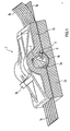
- Fig. 1 shows the cam 3 in its housing 2, through which a principal flexible flat strip cable 1a is led, on whose right side a branch flexible flat strip cable 1b is placed, which is introduced into the housing 2 as far as the cam and pressed by the latter in the area of contact onto the principal flexible flat strip cable 1a.
- the housing 2 consists of a lower part 2a and an upper part 2b, which are connected with one another by means of locking elements 17 shown in Fig. 3b, but not in Fig. 1.
- a groove 14 in the shape of a cylinder is formed into the lower part 2a of the housing, which represents a part of the bearing of cam 3.
- the cam 3 has a drum 3a and a lever 3b.
- the drum 3a is, as can best be seen in Fig 2, executed in one-half of the cross-section and in the other half of the cross-section the drum cover surface is formed by a flexible arm 7 extending over rather more than a quadrant of a circle. Its free end is bent radially towards the centre point of the drum and when the flexible arm 7 is relaxed, ends at a certain distance from the flat surface of the complete circle segment.
- the free end of the flexible arm 7 also has an impact surface 10 for the front edge of the branch flexible flat strip cable 1b. This is inserted via the principal cable 1a into the housing 2, until it impinges on the impact surface 10.
- the flexible arm 7 is bent so far inwards that its edge 9 is led away by a shoulder 11 which together form a click-and-pawl mechanism, so that the drum can be rotated by means of actuating the lever 3b into the end lock-in position shown in the lower part of Fig. 2.
- the shoulder 11 is arranged in the upper part 2b of the housing, somewhat above the level at which the principal cable 1a is substantially led into the housing.
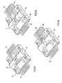
- Fig. 3 shows the process of assembly of the connection system.
- Fig. 3a shows the upper housing part 2b.
- Fig. 3b shows the lower housing part 2a, with the principal cable 1a lying inside it. Its part 13 from which insulation has been stripped lies in the vicinity of the cylinder cover segment-shaped groove 14.
- locking stops 15 are provided in the reception area for the principal cable 1a, which snap into the corresponding punched openings in the principal cable 1a.
- the upper housing part 2b is inserted onto the lower housing part 2a and locked with the latter by means of locking hooks 17.
- the upper housing part 2b has on one of its sides a reception slot 19 for the branch cable 1b (Fig.
Landscapes
- Coupling Device And Connection With Printed Circuit (AREA)
- Multi-Conductor Connections (AREA)
- Cable Accessories (AREA)
Abstract
Description
- Fig. 1
- shows a perspective view of an embodiment example of the flexible connection system according to the invention
- Fig. 2
- shows two cross-sectional views of the cam, respectively in the front lock-in and end lock-in position
- Fig. 3a to e
- show the process of assembly, when connecting the connection system to a principal flexible strip cable
Claims (10)
- A connection system for the connection of a branch flexible flat strip cable (1b) comprising a principal flexible flat strip cable (1a) with a cam (3) arranged in a housing (2), for the pressing against one another of areas of the cables (1a, 1b), from which insulation has been stripped.
- A connection system according to Claim 1, characterised by the fact that the cam (3) has a click and pawl mechanism (9, 11), which only allows a change from the loosened position into the end position, when the branch flexible flat strip cable (1b) is introduced into the cam drum (3) until it meets a stop.
- A connection system according to Claim 2, characterised by the fact that the cam (3) has a drum (3a), which forms in its cross-section an open circle segment, which is partially closed by an elastic arm (7) forming part of the drum cover, whose free end (8) is bent toward the axis of the drum with the formation of a locking edge (9) and has an impact surface (10) for the front edge of the branch flexible flat strip cable (1b), where the flexible arm (7) reduces, by means of pressing of the branch flexible flat strip cable (1b) against the impact surface (10), the radial distance of its locking edge (9) from the drum axis, so that the locking edge (9) rotates past a locking shoulder (11) correspondingly formed in the housing (2) and the cam (3) can be shifted into its locked position.
- A connection system according to Claim 3, characterised by the fact that the housing (2) has a lower part (2a) with a floor (12) for the reception and the fixing of the position of the principal flexible flat strip cable (1a), such that the area (13) from which insulation has been stripped, lies in a transverse groove (14) which forms part of the cam bearing, with locking stops (15) for the adjustment of the position of the cable (1a) via correspondingly punched openings (16) and with locking hooks (17) for the fastening of an upper part (2b) of the housing (2)
- A connection system according to Claim 4, characterised by the fact that the housing (2) has an upper part (2b) with a cam bearing (18), an introduction slots (19) for the branch flexible flat strip cables (1a) and (1b) and an opening (20) for the introduction of the operating lever (3b) of the cam (3)
- A connection system according to Claim 5, characterised by the fact that the locking shoulder (11) is arranged in the upper housing part (2b) of the housing (2) for locking the rotating movement of the cam (3)
- A connection system according to one of the Claims 2 to 6, characterised by the fact that the free end of the elastic arm (7) impinges against a surface (21) of the circular segment-shaped cut-out of the cam (3) and thus defines the exact positioning of the branch flexible flat strip cable (1b) with respect to the housing (2).
- A connection system according to one of the Claims 1 to 7, characterised by the fact that the cam (3) winds the branch flexible flat strip cable (1b) during its rotation, into its end position on the flexible arm (7) and the areas of contact (13) of the cables (1a, 1b) rub against one another.
- A connection system according to one of the Claims 2 to 7, characterised by the fact that the flexible arm (7) has on its outer face an elastomer or silicone transversal rib (22), in order to improve adhesion.
- A connection system according to Claim 4, characterised by the fact that the groove (14) in the lower part (2a) of the housing (2) has an elastomer or silicone transversal rib (23) in order to improve adhesion.
Applications Claiming Priority (2)
| Application Number | Priority Date | Filing Date | Title |
|---|---|---|---|
| DE10121307 | 2001-05-02 | ||
| DE10121307A DE10121307C1 (en) | 2001-05-02 | 2001-05-02 | Connection system for flex ribbon cable with eccentric |
Publications (3)
| Publication Number | Publication Date |
|---|---|
| EP1255323A2 true EP1255323A2 (en) | 2002-11-06 |
| EP1255323A3 EP1255323A3 (en) | 2004-03-24 |
| EP1255323B1 EP1255323B1 (en) | 2008-01-02 |
Family
ID=7683352
Family Applications (1)
| Application Number | Title | Priority Date | Filing Date |
|---|---|---|---|
| EP02008286A Expired - Lifetime EP1255323B1 (en) | 2001-05-02 | 2002-04-22 | A connection system for flexible flat strip cables with cam |
Country Status (4)
| Country | Link |
|---|---|
| US (1) | US6619964B2 (en) |
| EP (1) | EP1255323B1 (en) |
| AT (1) | ATE382967T1 (en) |
| DE (2) | DE10121307C1 (en) |
Cited By (1)
| Publication number | Priority date | Publication date | Assignee | Title |
|---|---|---|---|---|
| EP1583177A1 (en) * | 2004-04-01 | 2005-10-05 | Delphi Technologies, Inc. | Electrical connecting device |
Families Citing this family (7)
| Publication number | Priority date | Publication date | Assignee | Title |
|---|---|---|---|---|
| JP4722745B2 (en) * | 2006-03-29 | 2011-07-13 | モレックス インコーポレイテド | Relay connector |
| US7735807B2 (en) * | 2007-12-19 | 2010-06-15 | Safeworks, Llc | Tension holder for load lifting |
| US8529277B2 (en) * | 2011-02-18 | 2013-09-10 | Hi Rel Connectors, Inc | Flex to flex connection device |
| KR102528679B1 (en) * | 2015-07-01 | 2023-05-08 | 인텔 코포레이션 | FPC connectors for better signal integrity and design simplicity |
| US10958004B1 (en) * | 2019-10-31 | 2021-03-23 | Aptiv Technologies Limited | Location orientation of wiring relative to electrical connector |
| US11038288B2 (en) * | 2019-10-31 | 2021-06-15 | Aptiv Technologies Limited | Electrical splice connector |
| US11404836B2 (en) * | 2019-10-31 | 2022-08-02 | Aptiv Technologies Limited | Perpendicular electrical connector for wiring |
Family Cites Families (11)
| Publication number | Priority date | Publication date | Assignee | Title |
|---|---|---|---|---|
| US2952002A (en) * | 1958-09-19 | 1960-09-06 | Angele Wilhelm | Electrical connector for flat cables |
| US3114587A (en) * | 1961-10-02 | 1963-12-17 | Adolf L Herrmann | Flat cables and corresponding connector |
| EP0030639B1 (en) * | 1979-12-14 | 1984-07-04 | International Business Machines Corporation | Disconnectable electrically conductive cable connection |
| US4420206A (en) * | 1981-11-30 | 1983-12-13 | Western Electric Company, Inc. | Electrical connector |
| US4759726A (en) * | 1985-08-13 | 1988-07-26 | Reed Devices, Inc. | Screwless type electrical terminal block |
| US5281164A (en) * | 1992-07-20 | 1994-01-25 | Gan Jin Mou | Turn-and-press type of wire connector |
| JP2000030784A (en) * | 1998-05-08 | 2000-01-28 | Japan Aviation Electronics Ind Ltd | Electrical connector |
| DE19832012B4 (en) * | 1998-07-16 | 2006-01-12 | Leopold Kostal Gmbh & Co. Kg | Ribbon conductor with a branching and / or repair point and method for producing a branch and / or repair point on such a ribbon conductor |
| DE19832011B4 (en) * | 1998-07-16 | 2005-12-22 | Leopold Kostal Gmbh & Co. Kg | Ribbon cable with a provided for releasable connection terminal area |
| FR2788889B1 (en) * | 1999-01-26 | 2001-04-13 | Sylea | DEVICE FOR ELECTRICALLY CONNECTING AT LEAST TWO FLAT ELECTRIC CABLES |
| TW430169U (en) * | 1999-09-09 | 2001-04-11 | Hon Hai Prec Ind Co Ltd | Electrical connector |
-
2001
- 2001-05-02 DE DE10121307A patent/DE10121307C1/en not_active Expired - Fee Related
-
2002
- 2002-04-22 AT AT02008286T patent/ATE382967T1/en not_active IP Right Cessation
- 2002-04-22 EP EP02008286A patent/EP1255323B1/en not_active Expired - Lifetime
- 2002-04-22 DE DE60224320T patent/DE60224320D1/en not_active Expired - Lifetime
- 2002-05-01 US US10/137,877 patent/US6619964B2/en not_active Expired - Lifetime
Cited By (1)
| Publication number | Priority date | Publication date | Assignee | Title |
|---|---|---|---|---|
| EP1583177A1 (en) * | 2004-04-01 | 2005-10-05 | Delphi Technologies, Inc. | Electrical connecting device |
Also Published As
| Publication number | Publication date |
|---|---|
| ATE382967T1 (en) | 2008-01-15 |
| DE10121307C1 (en) | 2002-12-05 |
| EP1255323A3 (en) | 2004-03-24 |
| US20020192999A1 (en) | 2002-12-19 |
| EP1255323B1 (en) | 2008-01-02 |
| DE60224320D1 (en) | 2008-02-14 |
| US6619964B2 (en) | 2003-09-16 |
Similar Documents
| Publication | Publication Date | Title |
|---|---|---|
| CA2133275C (en) | Multi-channel duct for power and tel/comm conductors | |
| GB2130026A (en) | Electric connector | |
| US20080128164A1 (en) | Conduit connector assembly | |
| EP1255323B1 (en) | A connection system for flexible flat strip cables with cam | |
| KR20060125445A (en) | Waterproof connector | |
| JP6843973B2 (en) | Electrical connector for quick cable locking | |
| JPH10508418A (en) | Protective cover for electrical connector | |
| KR970072565A (en) | Swivel Connector | |
| CN103384945B (en) | Lever connector | |
| US6780046B2 (en) | Flex cable connection system comprising a spring housing | |
| JPH1186840A (en) | Battery fittings | |
| EP1255324B1 (en) | Electrical connector assembly for flexible flat cable | |
| US6215065B1 (en) | Bulkhead penetration system | |
| JP3803782B2 (en) | Wiring box | |
| WO2001057980A1 (en) | Waterproof enclosures | |
| CN105580217A (en) | Housing device for an electrical connection terminal and electrical connection terminal | |
| JPH103963A (en) | Waterproof connector | |
| US5104338A (en) | Cover device | |
| JP2022081173A (en) | Connector and wiring harness | |
| JP2002199546A (en) | Box for indoor wiring | |
| JP2001319721A (en) | Fixing structure of joint connector for wire harness | |
| CN223729348U (en) | Wire pressing clamp | |
| JP3932438B2 (en) | Wiring box | |
| JPH07288052A (en) | Grommet | |
| JP2008059755A (en) | Flat conductor electrical connector |
Legal Events
| Date | Code | Title | Description |
|---|---|---|---|
| PUAI | Public reference made under article 153(3) epc to a published international application that has entered the european phase |
Free format text: ORIGINAL CODE: 0009012 |
|
| AK | Designated contracting states |
Kind code of ref document: A2 Designated state(s): AT BE CH CY DE DK ES FI FR GB GR IE IT LI LU MC NL PT SE TR |
|
| AX | Request for extension of the european patent |
Free format text: AL;LT;LV;MK;RO;SI |
|
| PUAL | Search report despatched |
Free format text: ORIGINAL CODE: 0009013 |
|
| AK | Designated contracting states |
Kind code of ref document: A3 Designated state(s): AT BE CH CY DE DK ES FI FR GB GR IE IT LI LU MC NL PT SE TR |
|
| AX | Request for extension of the european patent |
Extension state: AL LT LV MK RO SI |
|
| 17P | Request for examination filed |
Effective date: 20040915 |
|
| AKX | Designation fees paid |
Designated state(s): AT BE CH CY DE DK ES FI FR GB GR IE IT LI LU MC NL PT SE TR |
|
| 17Q | First examination report despatched |
Effective date: 20041222 |
|
| GRAP | Despatch of communication of intention to grant a patent |
Free format text: ORIGINAL CODE: EPIDOSNIGR1 |
|
| GRAS | Grant fee paid |
Free format text: ORIGINAL CODE: EPIDOSNIGR3 |
|
| GRAA | (expected) grant |
Free format text: ORIGINAL CODE: 0009210 |
|
| AK | Designated contracting states |
Kind code of ref document: B1 Designated state(s): AT BE CH CY DE DK ES FI FR GB GR IE IT LI LU MC NL PT SE TR |
|
| REG | Reference to a national code |
Ref country code: GB Ref legal event code: FG4D |
|
| REG | Reference to a national code |
Ref country code: IE Ref legal event code: FG4D |
|
| REG | Reference to a national code |
Ref country code: CH Ref legal event code: EP |
|
| REF | Corresponds to: |
Ref document number: 60224320 Country of ref document: DE Date of ref document: 20080214 Kind code of ref document: P |
|
| RAP2 | Party data changed (patent owner data changed or rights of a patent transferred) |
Owner name: FCI |
|
| NLT2 | Nl: modifications (of names), taken from the european patent patent bulletin |
Owner name: FCI Effective date: 20080220 |
|
| PG25 | Lapsed in a contracting state [announced via postgrant information from national office to epo] |
Ref country code: NL Free format text: LAPSE BECAUSE OF FAILURE TO SUBMIT A TRANSLATION OF THE DESCRIPTION OR TO PAY THE FEE WITHIN THE PRESCRIBED TIME-LIMIT Effective date: 20080102 |
|
| NLV1 | Nl: lapsed or annulled due to failure to fulfill the requirements of art. 29p and 29m of the patents act | ||
| PG25 | Lapsed in a contracting state [announced via postgrant information from national office to epo] |
Ref country code: ES Free format text: LAPSE BECAUSE OF FAILURE TO SUBMIT A TRANSLATION OF THE DESCRIPTION OR TO PAY THE FEE WITHIN THE PRESCRIBED TIME-LIMIT Effective date: 20080413 Ref country code: LI Free format text: LAPSE BECAUSE OF FAILURE TO SUBMIT A TRANSLATION OF THE DESCRIPTION OR TO PAY THE FEE WITHIN THE PRESCRIBED TIME-LIMIT Effective date: 20080102 Ref country code: FI Free format text: LAPSE BECAUSE OF FAILURE TO SUBMIT A TRANSLATION OF THE DESCRIPTION OR TO PAY THE FEE WITHIN THE PRESCRIBED TIME-LIMIT Effective date: 20080102 Ref country code: CH Free format text: LAPSE BECAUSE OF FAILURE TO SUBMIT A TRANSLATION OF THE DESCRIPTION OR TO PAY THE FEE WITHIN THE PRESCRIBED TIME-LIMIT Effective date: 20080102 |
|
| REG | Reference to a national code |
Ref country code: CH Ref legal event code: PL |
|
| PG25 | Lapsed in a contracting state [announced via postgrant information from national office to epo] |
Ref country code: AT Free format text: LAPSE BECAUSE OF FAILURE TO SUBMIT A TRANSLATION OF THE DESCRIPTION OR TO PAY THE FEE WITHIN THE PRESCRIBED TIME-LIMIT Effective date: 20080102 |
|
| PG25 | Lapsed in a contracting state [announced via postgrant information from national office to epo] |
Ref country code: BE Free format text: LAPSE BECAUSE OF FAILURE TO SUBMIT A TRANSLATION OF THE DESCRIPTION OR TO PAY THE FEE WITHIN THE PRESCRIBED TIME-LIMIT Effective date: 20080102 Ref country code: PT Free format text: LAPSE BECAUSE OF FAILURE TO SUBMIT A TRANSLATION OF THE DESCRIPTION OR TO PAY THE FEE WITHIN THE PRESCRIBED TIME-LIMIT Effective date: 20080602 |
|
| EN | Fr: translation not filed | ||
| PG25 | Lapsed in a contracting state [announced via postgrant information from national office to epo] |
Ref country code: SE Free format text: LAPSE BECAUSE OF FAILURE TO SUBMIT A TRANSLATION OF THE DESCRIPTION OR TO PAY THE FEE WITHIN THE PRESCRIBED TIME-LIMIT Effective date: 20080402 Ref country code: DK Free format text: LAPSE BECAUSE OF FAILURE TO SUBMIT A TRANSLATION OF THE DESCRIPTION OR TO PAY THE FEE WITHIN THE PRESCRIBED TIME-LIMIT Effective date: 20080102 |
|
| PLBE | No opposition filed within time limit |
Free format text: ORIGINAL CODE: 0009261 |
|
| STAA | Information on the status of an ep patent application or granted ep patent |
Free format text: STATUS: NO OPPOSITION FILED WITHIN TIME LIMIT |
|
| PG25 | Lapsed in a contracting state [announced via postgrant information from national office to epo] |
Ref country code: MC Free format text: LAPSE BECAUSE OF NON-PAYMENT OF DUE FEES Effective date: 20080430 |
|
| 26N | No opposition filed |
Effective date: 20081003 |
|
| GBPC | Gb: european patent ceased through non-payment of renewal fee |
Effective date: 20080422 |
|
| PG25 | Lapsed in a contracting state [announced via postgrant information from national office to epo] |
Ref country code: DE Free format text: LAPSE BECAUSE OF FAILURE TO SUBMIT A TRANSLATION OF THE DESCRIPTION OR TO PAY THE FEE WITHIN THE PRESCRIBED TIME-LIMIT Effective date: 20080403 |
|
| PG25 | Lapsed in a contracting state [announced via postgrant information from national office to epo] |
Ref country code: FR Free format text: LAPSE BECAUSE OF FAILURE TO SUBMIT A TRANSLATION OF THE DESCRIPTION OR TO PAY THE FEE WITHIN THE PRESCRIBED TIME-LIMIT Effective date: 20081024 Ref country code: IE Free format text: LAPSE BECAUSE OF NON-PAYMENT OF DUE FEES Effective date: 20080422 |
|
| PG25 | Lapsed in a contracting state [announced via postgrant information from national office to epo] |
Ref country code: GB Free format text: LAPSE BECAUSE OF NON-PAYMENT OF DUE FEES Effective date: 20080422 |
|
| PG25 | Lapsed in a contracting state [announced via postgrant information from national office to epo] |
Ref country code: CY Free format text: LAPSE BECAUSE OF FAILURE TO SUBMIT A TRANSLATION OF THE DESCRIPTION OR TO PAY THE FEE WITHIN THE PRESCRIBED TIME-LIMIT Effective date: 20080102 |
|
| PG25 | Lapsed in a contracting state [announced via postgrant information from national office to epo] |
Ref country code: IT Free format text: LAPSE BECAUSE OF FAILURE TO SUBMIT A TRANSLATION OF THE DESCRIPTION OR TO PAY THE FEE WITHIN THE PRESCRIBED TIME-LIMIT Effective date: 20080102 |
|
| PG25 | Lapsed in a contracting state [announced via postgrant information from national office to epo] |
Ref country code: LU Free format text: LAPSE BECAUSE OF NON-PAYMENT OF DUE FEES Effective date: 20080422 |
|
| PG25 | Lapsed in a contracting state [announced via postgrant information from national office to epo] |
Ref country code: TR Free format text: LAPSE BECAUSE OF FAILURE TO SUBMIT A TRANSLATION OF THE DESCRIPTION OR TO PAY THE FEE WITHIN THE PRESCRIBED TIME-LIMIT Effective date: 20080102 |
|
| PG25 | Lapsed in a contracting state [announced via postgrant information from national office to epo] |
Ref country code: GR Free format text: LAPSE BECAUSE OF FAILURE TO SUBMIT A TRANSLATION OF THE DESCRIPTION OR TO PAY THE FEE WITHIN THE PRESCRIBED TIME-LIMIT Effective date: 20080403 |