EP1255309B1 - Battery arrangement for reducing battery terminal contact resistance - Google Patents
Battery arrangement for reducing battery terminal contact resistance Download PDFInfo
- Publication number
- EP1255309B1 EP1255309B1 EP02252821A EP02252821A EP1255309B1 EP 1255309 B1 EP1255309 B1 EP 1255309B1 EP 02252821 A EP02252821 A EP 02252821A EP 02252821 A EP02252821 A EP 02252821A EP 1255309 B1 EP1255309 B1 EP 1255309B1
- Authority
- EP
- European Patent Office
- Prior art keywords
- battery
- batteries
- contact
- terminal
- compartment
- Prior art date
- Legal status (The legal status is an assumption and is not a legal conclusion. Google has not performed a legal analysis and makes no representation as to the accuracy of the status listed.)
- Expired - Fee Related
Links
Images


Classifications
-
- H—ELECTRICITY
- H01—ELECTRIC ELEMENTS
- H01M—PROCESSES OR MEANS, e.g. BATTERIES, FOR THE DIRECT CONVERSION OF CHEMICAL ENERGY INTO ELECTRICAL ENERGY
- H01M50/00—Constructional details or processes of manufacture of the non-active parts of electrochemical cells other than fuel cells, e.g. hybrid cells
- H01M50/50—Current conducting connections for cells or batteries
- H01M50/502—Interconnectors for connecting terminals of adjacent batteries; Interconnectors for connecting cells outside a battery casing
-
- H—ELECTRICITY
- H01—ELECTRIC ELEMENTS
- H01M—PROCESSES OR MEANS, e.g. BATTERIES, FOR THE DIRECT CONVERSION OF CHEMICAL ENERGY INTO ELECTRICAL ENERGY
- H01M50/00—Constructional details or processes of manufacture of the non-active parts of electrochemical cells other than fuel cells, e.g. hybrid cells
- H01M50/10—Primary casings, jackets or wrappings of a single cell or a single battery
- H01M50/102—Primary casings, jackets or wrappings of a single cell or a single battery characterised by their shape or physical structure
- H01M50/109—Primary casings, jackets or wrappings of a single cell or a single battery characterised by their shape or physical structure of button or coin shape
-
- H—ELECTRICITY
- H01—ELECTRIC ELEMENTS
- H01M—PROCESSES OR MEANS, e.g. BATTERIES, FOR THE DIRECT CONVERSION OF CHEMICAL ENERGY INTO ELECTRICAL ENERGY
- H01M50/00—Constructional details or processes of manufacture of the non-active parts of electrochemical cells other than fuel cells, e.g. hybrid cells
- H01M50/20—Mountings; Secondary casings or frames; Racks, modules or packs; Suspension devices; Shock absorbers; Transport or carrying devices; Holders
- H01M50/204—Racks, modules or packs for multiple batteries or multiple cells
- H01M50/207—Racks, modules or packs for multiple batteries or multiple cells characterised by their shape
- H01M50/213—Racks, modules or packs for multiple batteries or multiple cells characterised by their shape adapted for cells having curved cross-section, e.g. round or elliptic
-
- H—ELECTRICITY
- H01—ELECTRIC ELEMENTS
- H01M—PROCESSES OR MEANS, e.g. BATTERIES, FOR THE DIRECT CONVERSION OF CHEMICAL ENERGY INTO ELECTRICAL ENERGY
- H01M50/00—Constructional details or processes of manufacture of the non-active parts of electrochemical cells other than fuel cells, e.g. hybrid cells
- H01M50/20—Mountings; Secondary casings or frames; Racks, modules or packs; Suspension devices; Shock absorbers; Transport or carrying devices; Holders
- H01M50/204—Racks, modules or packs for multiple batteries or multiple cells
- H01M50/207—Racks, modules or packs for multiple batteries or multiple cells characterised by their shape
- H01M50/216—Racks, modules or packs for multiple batteries or multiple cells characterised by their shape adapted for button or coin cells
-
- H—ELECTRICITY
- H01—ELECTRIC ELEMENTS
- H01M—PROCESSES OR MEANS, e.g. BATTERIES, FOR THE DIRECT CONVERSION OF CHEMICAL ENERGY INTO ELECTRICAL ENERGY
- H01M50/00—Constructional details or processes of manufacture of the non-active parts of electrochemical cells other than fuel cells, e.g. hybrid cells
- H01M50/50—Current conducting connections for cells or batteries
- H01M50/502—Interconnectors for connecting terminals of adjacent batteries; Interconnectors for connecting cells outside a battery casing
- H01M50/509—Interconnectors for connecting terminals of adjacent batteries; Interconnectors for connecting cells outside a battery casing characterised by the type of connection, e.g. mixed connections
- H01M50/51—Connection only in series
-
- H—ELECTRICITY
- H01—ELECTRIC ELEMENTS
- H01M—PROCESSES OR MEANS, e.g. BATTERIES, FOR THE DIRECT CONVERSION OF CHEMICAL ENERGY INTO ELECTRICAL ENERGY
- H01M50/00—Constructional details or processes of manufacture of the non-active parts of electrochemical cells other than fuel cells, e.g. hybrid cells
- H01M50/50—Current conducting connections for cells or batteries
- H01M50/502—Interconnectors for connecting terminals of adjacent batteries; Interconnectors for connecting cells outside a battery casing
- H01M50/509—Interconnectors for connecting terminals of adjacent batteries; Interconnectors for connecting cells outside a battery casing characterised by the type of connection, e.g. mixed connections
- H01M50/512—Connection only in parallel
-
- H—ELECTRICITY
- H01—ELECTRIC ELEMENTS
- H01M—PROCESSES OR MEANS, e.g. BATTERIES, FOR THE DIRECT CONVERSION OF CHEMICAL ENERGY INTO ELECTRICAL ENERGY
- H01M50/00—Constructional details or processes of manufacture of the non-active parts of electrochemical cells other than fuel cells, e.g. hybrid cells
- H01M50/50—Current conducting connections for cells or batteries
- H01M50/502—Interconnectors for connecting terminals of adjacent batteries; Interconnectors for connecting cells outside a battery casing
- H01M50/519—Interconnectors for connecting terminals of adjacent batteries; Interconnectors for connecting cells outside a battery casing comprising printed circuit boards [PCB]
-
- Y—GENERAL TAGGING OF NEW TECHNOLOGICAL DEVELOPMENTS; GENERAL TAGGING OF CROSS-SECTIONAL TECHNOLOGIES SPANNING OVER SEVERAL SECTIONS OF THE IPC; TECHNICAL SUBJECTS COVERED BY FORMER USPC CROSS-REFERENCE ART COLLECTIONS [XRACs] AND DIGESTS
- Y02—TECHNOLOGIES OR APPLICATIONS FOR MITIGATION OR ADAPTATION AGAINST CLIMATE CHANGE
- Y02E—REDUCTION OF GREENHOUSE GAS [GHG] EMISSIONS, RELATED TO ENERGY GENERATION, TRANSMISSION OR DISTRIBUTION
- Y02E60/00—Enabling technologies; Technologies with a potential or indirect contribution to GHG emissions mitigation
- Y02E60/10—Energy storage using batteries
Landscapes
- Chemical & Material Sciences (AREA)
- Chemical Kinetics & Catalysis (AREA)
- Electrochemistry (AREA)
- General Chemical & Material Sciences (AREA)
- Battery Mounting, Suspending (AREA)
- Connection Of Batteries Or Terminals (AREA)
Description
- The present invention relates to a battery compartment and to a battery powered device. More particularly, it relates to decreasing battery terminal contact resistance attributable to the presence of an insulating contaminant layer on the battery terminals.
- Electrical devices commonly derive their power by way of one or more batteries that are housed within a compartment associated with the electrical device. The battery compartment typically is integral with the electrical device. Alternatively, the battery compartment can be provided remotely from the electrical device with a connection thereto via conductor elements such as electrical wires.
- There are numerous types of primary (non-rechargeable) and secondary (rechargeable) batteries. Dry cell batteries are commercially available in a number of well-known sizes and configurations such as the standardized AAA, AA, C, and D battery sizes. Miniature batteries, also referred to as watch, disc, dish, and button batteries, are also available in standard sizes and are commonly used in hearing aids, electric wristwatches and other devices.
- Dry cell battery compartments have a positive contact, commonly in the form of a planar tab or a conical coiled spring, for electrically contacting the negative terminal of an installed dry cell battery. A negative contact, commonly in the form of a planar tab, is provided in the compartment for electrically contacting the positive terminal of an installed dry cell battery. Planar and dimpled tabular contacts are commonly used in miniature battery compartments. When one or more batteries are installed in such battery compartments, the device serves as an electrical load placed across the terminals of the installed batteries.
- In compartments that require more than one dry cell battery, the batteries are housed in a series or parallel arrangement. In a series arrangement, the batteries are positioned "head to tail" with the planar surface of the positive terminal button abutting the negative terminal surface of the forward adjacent battery, with the batteries having parallel or coexistent longitudinal axes; that is, the batteries form a straight line. As a result, batteries arranged in this manner are said to be "linearly aligned".
- A well-documented problem with standard dry-cell, miniature and other types of batteries is the oxidation and sulfidation of the battery terminals. Oxide and sulfide layers often develop with time such as from when the batteries are manufactured to when they are ultimately used. In addition, galvanic corrosion of the battery terminals can occur in certain circumstances and environments. These oxide, sulfide and corrosive films are surface contaminants that insulate the battery terminal. Of particular relevance to the present invention is the increased battery contact resistance caused by this insulating contaminant layer. Contact resistance is the electrical resistance in the battery circuit attributable to the physical contact between adjacent batteries and between the batteries and the device. In circumstances in which the terminals have an insulting contaminant layer, the contact resistance can be significant, consuming valuable battery power, particularly in high current applications. This results in the rapid depletion of the installed batteries, decreasing device availability and increasing the rate at which the batteries need to be replaced or recharged. Furthermore, such a high contact resistance decreases the maximum current available from the installed batteries, making certain battery arrangements unsuitable for use in high current devices.
- For example, two 1.2-volt dry cell batteries arranged in series provide 2.4 volts. In a high current application of 5 amperes, the batteries deliver 12 watts of power. If the contact resistance increases from a nominal 0.06 ohms to 0.2 ohms due the presence of an insulating contaminant layer on one or more of the battery terminals, the power consumed overcoming the contact resistance increases from 1.5 to 5 watts. In other words, 40% of the available power is consumed by the contact resistance. This reduces the power and current available to the device. In addition, the lost power essentially heats the battery terminals and/or device contacts. This can damage or degrade the batteries, damage the battery compartment and increase the risk of fire.
- One traditional approach to solving this problem has been to provide the operator with a separate dimpled piece of sheet metal to insert between neighboring linearly aligned batteries. This approach has some drawbacks. For example, the additional part increases product cost. It also adds complexity, making it difficult for the user to install quickly and easily the batteries. The user must install a first battery, position the sheet metal intermediate contact in the proper position, and then insert the second battery while retaining the sheet metal in its proper position. Thus, such supplemental parts are often used improperly or misplaced or lost and not used at all.
- An insulating contaminant layer on the battery terminal also increases the contact resistance between the batteries and device. For example, the first battery in a series battery arrangement is positioned with the planar surface of its positive terminal button parallel to and in contact with a planar negative tab contact of the device. The last battery in the series battery arrangement is positioned such that its planar negative terminal surface is parallel to and in contact with a planar conical coiled spring winding or contact tab. Conventional conical coiled spring contacts have a series of helical windings, with the upper winding residing in a plane substantially parallel to and in contact with the negative battery terminal surface. Similarly, in parallel arrangements, the batteries are each positioned with their positive and negative terminals contacting the opposing polarity contacts of the battery compartment in a similar manner. The planar tab and planar conical coiled spring winding can not penetrate the insulating contaminate layer coating the battery terminals.
-
US 4,008,356 discloses a casing for retaining therein a series of dry cells provided with cell holding members which hold the cells allowing movement in one direction of the cells, and a member for moving the cells in said direction. The direction in which the cells are made movable is lateral to the direction of connection of the cells connected in series in a line in the casing so that the electrodes of the cells connected with the electrodes adjacent thereto are abraded when the cells are moved in said direction by the movable member. The movable member may be a cover of the housing of the casing or other member associated with the shutter release mechanism or the like.
The present invention is directed to a battery arrangement for two or more standard dry cell or miniature batteries. The batteries are serially-aligned with their respective longitudinal axes intersecting at an angle which causes the batteries to contact each other with a minimal accessible surface area of at least one of the terminals, such as the edge of a positive terminal button edge of a dry cell battery or an edge of the positive terminal casing of a miniature battery. The battery arrangement of the present invention minimizes the contact surface area between contacting terminals of adjacent batteries, thereby maximizing, for a given compression force, the localized contact pressure between those batteries. This advantageously ruptures or removes substantially any insulating contaminant layer disposed on the contacting regions of the battery terminals thereby reducing battery-to-battery contact resistance. Another advantage of the present invention is that the user does not have to perform any action or use any additional components such as additional springs or dimple sheets to achieve this significant reduction in contact resistance. - An aspect of the invention is summarized below, along with different embodiments that may be implemented. It should be understood that the embodiments are not necessarily inclusive or exclusive of each other and may be combined in any manner that is non-conflicting and otherwise possible regardless of which aspect of the invention they are associated with. It should also be understood that these summarized aspects of the invention are exemplary only and are considered to be non-limiting.
- In one aspect of the invention there is provided a battery compartment for storing at least two batteries in a serially aligned arrangement, characterised in that the battery compartment is configured to align the batteries with the respective longitudinal axes non-parallel so that the area of electrical contact between the terminals of the batteries is less than the area of electrical contact between the terminals of the batteries if aligned with said axes parallel.
- A number of preferred embodiments of the present invention will now be described with reference to the following detailed description and from the accompanying figures. This description is given by way of example only and in no way restricts the scope of the invention. In the drawings, like reference numerals indicate identical or functionally similar elements. Additionally, the left most one or two digits of a reference numeral identify the drawing in which the reference numeral first appears. In the figures:
-
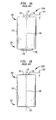
Figures 1A and 1B are schematic side views of two prior art dry cell batteries that can be arranged in accordance with embodiments of the present invention. -
Figures 2A and 2B are schematic side views of two prior art miniature batteries that can be arranged in accordance with embodiments of the present invention. -
Figure 3 is a schematic diagram of two dry cell batteries in a serially-aligned arrangement with their respective longitudinal axes intersecting in accordance with one embodiment of the present invention. -
Figure 4 is a schematic diagram of two miniature batteries in a serially aligned arrangement with their respective longitudinal axes intersecting in accordance with one embodiment of the present invention. -
Figure 5 is an illustration of a device contact tab in accordance with one aspect of the present invention. -
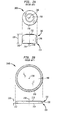
Figure 6 includes a top, front and side views of a conical coiled spring device contact with an eccentric contact point in accordance with one embodiment of the present invention. -
Figure 7A includes a top, front and side views of a conical coiled spring device contact with an eccentric contact point in accordance with an alternative embodiment of the present invention. -
Figure 7B is an isometric view of a conical coiled spring device contact with more than one eccentric contact point in accordance with an alternative embodiment of the present invention. -
Figure 8 is an illustration of a dry cell battery compartment that retains the batteries in a serially-aligned, intersecting longitudinal axis arrangement in accordance with one embodiment of the present invention. -
Figure 9 is an illustration of a dry cell battery compartment that retains the batteries in a serially-aligned, intersecting longitudinal axis arrangement in accordance with one embodiment of the present invention. -
Figure 10 is an illustration of a dry cell battery compartment that retains the batteries in a serially-aligned, intersecting longitudinal axis arrangement in accordance with one embodiment of the present invention. -
Figure 11A is an illustration of a battery compartment for miniature batteries that retains the batteries in a serially-aligned, intersecting longitudinal axis arrangement in accordance with one embodiment of the present invention. -
Figure 11B is an illustration of a battery compartment for miniature batteries that retains the batteries in a serially-aligned, intersecting longitudinal axis arrangement in accordance with an alternative embodiment of the present invention. -
Figure 12 is a schematic block diagram of a hand-held scanner having a battery compartment in accordance with one embodiment of the present invention. - The present invention is directed to methods and apparatus that minimize battery-to-battery and battery-to-device contact resistance by rupturing or removing an insulating contaminant layer disposed on the portions of the battery terminals that contact each other or that contact the contacts of a battery compartment. Specifically, the present invention arranges standard dry cell and miniature batteries such that a minimum surface area of the terminals contacts of an adjacent battery terminal or device contact. A given compression force applied to the serially-aligned batteries in the battery compartment results in a maximum contact pressure sufficient to rupture the insulating contaminant layer disposed on the surface of the abutting battery terminals and/or abutting battery terminal and device contact. Preferably, a relative lateral motion is imparted between adjacent batteries and/or a battery and device contact when the batteries are installed in the battery compartment to facilitate the penetration of the insulating contaminant layer.
- The disclosed embodiments of the present invention are directed to a battery arrangement for two or more standard dry cell or miniature batteries with their respective longitudinal axes intersecting at an angle which causes the batteries to contact each other with a minimal accessible surface area of at least one of the terminals, such as the edge of a positive terminal button of a dry cell battery or an edge of the positive casing of a miniature battery. Providing battery-to-battery and battery-to-device contact at only this terminal edge region minimizes the contact surface area and maximizes the localized contact pressure. This ruptures the insulating contaminant layer on the contacting terminal regions thereby reducing contact resistance attributable thereto. Importantly, the resulting decrease in contact resistance is achieved without reconfiguring the batteries; that is, standard, commercially available batteries are used, and without using additional components such as springs or dimple sheets.
- The present invention is also directed to a conical coiled spring battery contact for use in a battery compartment. The conical coiled spring contact is configured with an upper end turn that is bent to form one or more terminal contact regions having a minimal surface area for contacting a terminal of an abutting battery. The contact region(s) each provide, for a given compression force, a contact point that imparts a pressure sufficient to rupture an insulating contaminant layer on the abutting battery terminals. Preferably, the conical coiled spring contact has an axis of rotation defined by the windings with the terminal contact point(s) laterally offset from the axis. This causes regions of the windings in this lateral direction to compress more that other regions of the windings in response to an axial compression force applied by an abutting battery. This in turn causes the terminal contact point(s) to shift further in the lateral direction as the contact spring is compressed. As this occurs, the terminal contact point(s) scrape against the terminal of the installed battery, removing substantially any insulating contaminant layer disposed on the battery terminal.
- A battery, sometimes referred to as an electric cell, is a device that converts chemical energy into electricity. As used herein, a battery can consist of one cell alone as well as two or more cells connected in series or parallel within a single casing. Each cell consists of a liquid, paste or solid electrolyte, a positive electrode and a negative electrode. The electrolyte serves as an ionic conductor; one of the electrodes reacts with the electrolyte to produce electrons while the other electrode accepts the electrons. When connected across a load, such as when installed in a device battery compartment, this reaction causes current to flow from the battery and power to be consumed. Although the present invention can be applied to and operate with many types of rechargeable and non-rechargeable batteries; the present invention, solely for the ease of understanding, will be discussed in connection with two of the more common types of batteries, dry cell batteries and miniature batteries. Such batteries have different chemistries such as Lithium Ion, Nickel Cadmium, Nickel Metal Hydride, rechargeable alkaline, and others.
- A perspective view of two commonly available, standard dry cell batteries is provided in
Figures 1A and 1B .Dry cell batteries dry cell batteries 100 or, simply, battery orbatteries 100.Dry cell batteries 100 can be either primary or secondary batteries. Primary batteries are batteries in which the electrolytes cannot be reconstituted into their original form once the energy stored in the battery has been converted into a current; that is, they are non-rechargeable. Primary battery cells were originally referred to as a Leclanché cell in honor of its inventor, French chemist Georges Leclanché who invented the dry cell battery in the 1860's. Other names given to this type of battery include, for example, a flashlight battery, a voltaic battery, an alkaline battery, etc.Dry cell batteries 100 can also be secondary batteries. Secondary batteries can be recharged by reversing the chemical reaction in the battery; that is, they are rechargeable. Such a battery was invented in 1859 by the French physicist Gaston Planté. The chemical composition of rechargeable and non-rechargeabledry cell batteries 100, some of which are noted above, are well known and not described further herein. - The size and configuration of primary dry cell batteries and, more recently, secondary dry cell batteries are specified by ANSI standards, and are commercially available in the standardized AAA, AA, C, and D battery sizes. As such, a common feature of all such
dry cell batteries 100 is its configuration.Figures 1A and 1B are side views of two prior artdry cell batteries Dry cell batteries 100 includes a cylindrical shell or casing 108 defining ahead region 102 and atail region 104. Apositive terminal 106 is disposed athead region 102 while anegative terminal 108 is disposed attail region 104. The internal configuration and chemistry ofdry cell batteries 100 varies, and is well known in the art. However, in all cases,positive terminal 106 is a formed cylindrical protrusion extending from casing 110, commonly referred to as a button.Terminal button 106 has a curved orparabolic edge 112 while thetop surface 114 ofpositive terminal button 106 is substantially planar. Alongitudinal axis 118 extends throughbatteries 100 fromnegative terminal 108 topositive terminal 106. Planar surfaces 116 and 114 are orthogonal tolongitudinal axis 118. The height orthickness 120 ofpositive terminal button 106 varies, as shown by the twoillustrative batteries - Examples of the above batteries are available from Duracell, Inc., and Eveready Battery Company, Inc. DURACELL® batteries are described in detail at www.duracell.com, while the EVEREADY® batteries are described in detail at www.eveready.com. (DURACELL is a registered trademark of Duracell Inc., a division of The Gillette Company. EVEREADY is a registered trademark of the Eveready Battery Company, Inc.) Because the dimensions of these and other dry cell batteries have been standardized and are specified by ANSI standards, the dimensions of such batteries will be substantially the same, within the specified tolerances, regardless of manufacturer.
-
Figures 2A and 2B are top and side views of two embodiments of another common battery in use today, referred to herein as a miniature batteries 200 (collectively and generally referred to as miniature battery 200 or, simply battery or batteries 200). Miniature battery 200 is also referred to as a watch, coin, button, disc, dish and mercury battery. Today, miniature battery 200 is commonly available in chemistries such as mercury, lithium and manganese dioxide, silver oxide, and others. - Miniature batteries 200 are made in the shape of a small flat disk for use in, for example, hearing aids, photoelectric cells and electric wristwatches. A miniature battery 200 includes a disc-shaped shell or casing 210 defining a
head region 202 and atail region 204. Apositive terminal 206 is located attail region 204 while anegative terminal 208 is located athead region 202. The internal configuration of miniature batteries is considered to be well known in the art and is not described further herein. The height orthickness 220 of miniature batteries 200 varies, as shown by the twoillustrative batteries 200A and 200B.Negative terminal 208 may be a small cylindrical raised surface, as shown onbattery 200A, or it may be flush with the surface, as in battery 200B. In battery 200B,negative terminal 208 does not extend to the periphery ofbattery casing 210. As shown in the top view, it is a substantially circular region with a diameter slightly less than the diameter ofbattery casing 210. As withdry cell batteries 100, thetop surface 216 ofnegative terminal 208 and thesurface 214 ofpositive terminal 206 are substantially planar. Each battery 200 has anaxis 218 through its center, extending frompositive terminal 206 tonegative terminal 208. Planar surfaces 214, 216 are substantially orthogonal tolongitudinal axis 218. - Battery compartments currently available today hold one or more batteries either in a laterally adjacent or a serially aligned manner. In the laterally-adjacent arrangement, the batteries are each electrically connected to a positive and negative device contact, while in the serially-aligned arrangement, the batteries are aligned with their longitudinal axes parallel or coextensive with each other. Batteries in this latter conventional arrangement are referred to herein as being "linearly aligned" with each other; that is, they form a straight line. In both arrangements, the longitudinal axes of an installed battery is also parallel or coextensive with a central axis of the conical coiled spring contact and an orthogonal surface vector of the device tab contact. Such arrangements dictate that conventional
dry cell batteries 100 and miniature batteries 200 haveplanar surfaces - In contrast to such approaches, the present invention includes a battery compartment in which one or more batteries are arranged so that a minimal surface area of their respective terminals contacts each other. Specifically, the inventor has observed that existing
dry cell batteries 100 and miniature batteries 200 have an edge on at least one of their terminals that is accessible by a planar, opposing-polarity terminal of an adjacent battery. Specifically, referring again toFigures 1A and 1B ,positive terminals 106 ofdry cell batteries 100 have, as noted, a curved orparabolic edge surface 112 around the periphery of planar positiveterminal surface 114. Sincepositive terminal button 106 is raised fromhead portion 102 and the remainder of the positive terminal surface,edge 112 is accessible by a planar, opposing-polarity battery terminal or device contact that is nonparallel to theplanar surface 114 ofpositive terminal 106. Referring again toFigures 2A and 2B ,positive terminal 206 of miniature batteries 200 includes a casing with anaccessible edge 212.Edge 212 is, as noted, a curved or parabolic surface around the periphery of planar positiveterminal surface 214. Becauseedge 212 is on the periphery of the battery casing,edge 212 2 is a region of the positive terminal surface that is accessible by a planar, opposing-polarity battery terminal or device contact that is nonparallel to theplanar surface 214 ofpositive terminal 206. - Battery compartments configured in accordance with the present invention arrange the installed batteries with
terminal edges positive battery terminals negative terminals terminal edge surfaces batteries 100, 200. This contact pressure is significantly greater that the contact pressure provided by conventional battery arrangements subject to the same compression force. The high pressure contact point ruptures an insulating contaminant layer onterminals -
Figures 3 and 4 are illustrations of two dry cell batteries and two miniature batteries, respectively, arranged in accordance with various embodiments of the present invention.Figure 5 is a schematic diagram of a device contact and a dry cell battery arranged in accordance with another embodiment of the invention. Referring toFigure 3 , twodry cell batteries 100, labeled for ease of reference asbatteries 302A and 302B inFigure 3 , are arranged in accordance with the present invention. Specifically,dry cell battery 302A is positioned in front of dry cell battery 302B. Aterminal contact point 304 is the only point of contact betweenpositive terminal 106 of battery 302B andnegative terminal 108 ofbattery 302A.Terminal contact point 304 is that region of positiveterminal edge 112 that contacts planarsurface 116 ofnegative terminal 108. To achieve this, dry cell batteries 302 are arranged such that theirlongitudinal axes predetermined angle 308.Angle 308 ranges from an angle greater than that at whichplanar surfaces casings 110 contact each other and cause the separation ofterminals 106, 108 (which varies with the dimensions of dry cell batteries 100). - Similarly, referring to the miniature battery arrangement illustrated in
Figure 4 , two miniature batteries 200, labeled for ease of reference asbatteries Figure 4 , are arranged in accordance with the present invention. Specifically,miniature battery 402A is positioned in front ofminiature battery 402B. Aterminal contact point 404 is the only point of contact betweenpositive terminal 206 ofbattery 402B andnegative terminal 208 ofbattery 402A.Terminal contact point 404 is that region of positiveterminal edge 212 that contacts planarsurface 216 ofnegative terminal 208. To achieve this, miniature batteries 402 are arranged such that their longitudinal axes 218A and 218B intersect each other at apredetermined angle 408.Angle 408 ranges from an angle greater than that at whichplanar surfaces - As will be described in detail below, battery compartments of the present invention also impart a relative lateral movement between adjacent battery terminals and/or between a battery terminal and device contact when the terminals and/or contacts come into contact with each other, preferably while under some compression force. This is illustrated with arrows in
Figures 3 and 4 . Referring toFigure 3 , one battery 302 can move in the direction ofarrow opposing direction -
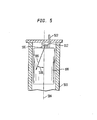
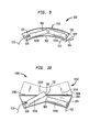
Figure 5 is a schematic diagram of a contact tab configured in accordance with the present invention illustrating one implementation to reduce battery-to-device contact resistance. Referring toFigure 5 , in a drycell battery compartment 500 configured in accordance with the present invention, anegative contact tab 502 is arranged so as not to be parallel with thesurface 114 ofpositive battery terminal 106. Rather,device terminal tab 502 is positioned so as to contact only positiveterminal edge 112 of an installedbattery 100. This provides acontact point 304 betweenpositive battery terminal 106 andnegative device terminal 502 that imparts a greater contact pressure than would otherwise be imparted in conventional arrangements. The relative angles and other configuration details can be easily determined by those of ordinary skill in the art given the dimensions ofbattery 100. -
Figure 6 includes side, top and front views of a conical coiled spring contact in accordance with one aspect of the present invention. Conicalcoiled spring contact 600 reduces or eliminates contact resistance between a battery terminal and conical coiledspring contact 600 by providing a high pressure contact point and, preferably, a contact wiping action that ruptures, scrapes or otherwise removes an insulting contaminant layer on an abutting battery terminal. - A conical coiled
spring contact 600 of the present invention has a series of windings orconvolutions 602. In the embodiment shown inFigure 6 ,windings 602 each has a diameter that is greater toward alower end turn 614 and smaller toward anupper end turn 608. As a result, the coiledspring contact 600 is approximately conical in shape. In alternative embodiments, the diameter of each winding 602 does not vary substantially or varies differently than that shown inFigure 6 . As shown inFigure 6 , the windings have a central axis ofrotation 604. The axis of the conical coiled spring is preferably parallel to or coextensive withaxis -
Lower end turn 614 defines abottom face 612 whileupper end turn 608 definestop face 606 of conical coiledspring contact 600. Typically,bottom face 612 is secured to a region of an implementing battery compartment or circuit board whiletop face 606 contacts abattery 100, 200 installed therein. In contrast to conventional conical coiled spring contacts that, when compressed, maintains a flush contact between the surface along the length of the upper winding and the terminal surface, conical coiledspring contact 600 is configured with anupper end turn 608 that is bent to form aterminal contact region 610 for contactingnegative terminal dry cell batteries 100 or miniature batteries 200.Contact region 610 provides, for a given compression force, a contact point that imparts a pressure sufficient to rupture an insulating contaminant layer on the abutting battery terminals. - Furthermore,
contact point 610 is eccentric; that is,contact point 610 is spaced laterally fromaxis 604 of conical coiledspring 600. As a result, as abattery 100, 200 compresses conical coiledspring contact 600,contact point 610 shifts laterally from its shown position in the direction ofeccentricity 616. This imparts a lateral sliding motion against the abutting battery terminal that scrapes away a substantial portion of any existing insulating contaminant layer. In addition, as noted,contact point 610 thereafter provides a contact point that imparts a pressure sufficient to rupture any remaining insulating contaminant layer. - Conical
coiled spring contact 600 is preferably formed of a highly conductive material, and is preferably unitary. In accordance with one aspect of the invention, a lead (not shown) is attached todistal end 620 of conical coiledspring contact 600 in any well-known manner. For example, a standard crimp-on connector is used in one embodiment. In another embodiment, the lead is soldered onto conicalcoiled spring 600 using any of a myriad of known techniques. In a further embodiment, an electrically conductive sleeve is securely connected to conicalcoiled spring 600. The sleeve has an interior diameter sufficient to receive and retain the lead. - This is in contrast to conventional techniques that connect the lead to the opposite end of the conical coiled spring contact; that is, to
lower end turn 614. This conventional approach has been universally implemented because thelower end turn 614 is the portion of conventional spring contacts that is connected to the printed circuit board or battery compartment. In contrast, the present invention reduces substantially the significant bulk resistance of conical coiled spring contacts. For example, a typical conical coiled spring contact of a AA battery compartment uses 140-150 mm in length of 0.81 mm diameter wire. The resistance of such a coiled spring contact is approximately 0.211 ohms, 0.527 ohms, 0.337 ohms and .039 ohms when the spring contact material is 302 stainless steel, music wire, Be-Cu C17200 and Phosphor Bronze 521, respectively. The present invention reduces the length of the coiled spring contact through which current travels from the approximate 140-150 mm to approximately 4 mm by connecting the lead todistal end 620. This, in turn, reduces the bulk resistance of the conical coiled spring contact, for each of the noted materials, to .0055 ohms, 0.0139 ohms, 0.0044 ohms and 0.001 ohms, respectively. Furthermore, the conical coiled spring contact implementing this feature of the present invention can be used in place of conventional tab or leaf spring battery contacts due to the reduced bulk resistance. Such an application is cost effective because coiled spring contacts are significantly less expensive to manufacture than traditional dimpled leaf springs commonly used in conventional battery compartments. For example, the equipment to manufacture the conical coiled spring contact is significantly less expensive than the sheet metal die and related equipment to make the leaf springs. In addition, there is minimal material waste generated during the manufacturing process. Further, less material is used for each type of contact. -
Figure 7A includes a side, top and front view of a conical coiled spring contact in accordance with an alternative embodiment of the present invention. As with conicalcoiled spring 600, conical coiledspring contact 700 reduces or eliminates contact resistance between an abutting battery terminal and conical coiledspring contact 700 by providing a high pressure contact point that ruptures, scrapes or otherwise removes an insulting contaminant layer on thecontact 700 and abutting battery terminal. - Conical
coiled spring contact 700 has a series of windings orconvolutions 702. In the embodiment shown inFigure 7A , conical coiledspring contact 700 is conical in shape although it can have other configurations. As shown inFigure 7A , thewindings 702 have a central axis ofrotation 704. - A
lower end turn 714 defines abottom face 712 designed to be secured to a region of an implementing battery compartment while anupper end turn 708 definestop face 706 that contacts abattery 100, 200. Conicalcoiled spring contact 700 is configured with anupper end turn 708 that is bent to form an eccentricterminal contact point 710 for contactingnegative terminal dry cell batteries 100 or miniature batteries 200.Eccentric contact point 710 shifts laterally in the direction ofeccentricity 716 asspring 700 is compressed, providing a lateral sliding motion against the abutting battery terminal and, thereafter, providing a high pressure contact point that can rupture an insulating contaminant layer on the abutting battery terminal. - Referring back to
Figure 6 ,contact point 610 of conical coiledspring contact 600 is formed with a hairpinupper end turn 608. As shown,distal end 620 ofcoil 600 is directed towardbottom face 612 alongaxis 604. Coiled spring contact 700 (Figure 7 ) shows an alternative embodiment.Contact point 710 of conical coiledspring contact 700 is formed with a slight bend inupper end turn 708. The apex of this bend formscontact point 710. It should become apparent to those of ordinary skill in the art that in alternative embodiments, conical coiled spring contact can have other configurations that provide an eccentric contact point attop face -
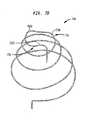
Figure 7B is an isometric view of a conical coiled spring contact with more than one eccentric contact point in accordance with an alternative embodiment of the coiled spring contact of the present invention. Conicalcoiled spring contact 750 reduces or eliminates contact resistance between an abutting battery terminal and conical coiledspring contact 750 by providing multiple high pressure contact points 752 each of which ruptures, and preferably scrapes, an insulting contaminant layer on contact point 752 and abutting battery terminal. - Conical
coiled spring contact 750 is constructed similarly tocontacts contacts spring contact 750 is configured with anupper end turn 756 with bends that form three eccentricterminal contact regions 752A-752C onupper face 754 for contacting an abutting battery terminal. The relative location onupper end turn 756 of each terminal contact point 752 can be selected to prevent or induce the lateral shift noted above with reference tocontacts - As noted, in a dry cell battery compartment of the present invention the dry cell batteries are aligned with the longitudinal axes of neighboring batteries intersecting at an angle that results in the high pressure contact point of the positive terminal edge contacting the planar negative terminal of the neighboring battery. Such a battery compartment can have a number of configurations, some of which are described below.
-
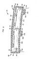
Figure 8 is an illustration of a dry cell battery compartment in accordance with one embodiment of the present invention.Battery compartment 800 includes ahousing 802 configured to receive twodry cell batteries 814 A and 814B in a serially aligned arrangement.Dry cell battery 814A is in a forward position ofcompartment 800 while dry cell battery 814B is in a rear position.Housing 802 includes ahousing base 804 with ahousing door 806 together defining an interior region ofcompartment 800. -
Housing base 804 includes abase floor 812 with an integralrear sidewall 808 andforward sidewall 810. Secured torear sidewall 808 is a conicalcoiled spring 600. Conicalcoiled spring 600 contactsnegative terminal 104 of battery 814B. Attached to conical coiledspring contact 600 is anelectrical lead 828.Forward sidewall 810 has secured to it a fixeddomed contact 820 for electrically contactingpositive terminal 106 offorward battery 814A. Alead 826 is electrically connected to contact 820. Together, leads 828 and 826 provide current to the hosting device. Fixeddomed contact 820 preferably has multiple contact domes each with a small radius to provide low contact resistance. In one embodiment, the domes are spaced closely and have a lead-in angle that prevents positive terminal 106 from being inadvertently retained withinhousing base 804. Conicalcoiled spring 600 has the structure and performs the functions as those noted above, while fixed domed contact is conventional. It should be understood, however, that both fixeddomed contact 820 and conical coiledspring contact 600 can be replaced with contacts having other configurations. - In the embodiment illustrated in
Figure 8 , batteries 814 are shown in the fully installed position, with theangle 308 between their longitudinal axes 118 (Figure 1 ) being approximately 7 degrees. It should be understood, however, that this angle is by way of example only and that batteries 814 can be arranged such that theangle 308 between their longitudinal axes is some other angle. In this illustrative embodiment, this angle is maintained by securing the batteries 814 against a floor having different slopes. As shown,housing floor 812 has one region with a surface that supportsbattery 814A and a second region with a surface that supports battery 814B. The surface ofhousing floor 812 in each of these regions has a relative angle and configuration to maintain the batteries 814 with their longitudinal axes at the desired intersecting arrangement. -
Housing floor 812 includesresilient supports 816A and 816B for supportingbatteries 814A, and 814B, respectively. Resilient supports 816A and 816B reside inchannel housing floor 812. Resilient supports 816 are made of an elastomeric or other flexible supporting material. Initially, batteries 814 are placed inhousing base 804 loosely. First,battery 814A is installed against fixedcontact 820. When installed,battery 814A rests onresilient support 816A, elevated temporarily off of the surface ofhousing floor 812.Forward sidewall 810 includes a cantileveredoverhang 818 that extends over the location at whichbattery 814A is to be located.Overhang 818 provides the operator with a guiding surface for installingbattery 814A. Then, battery 814B is installed against conicalcoiled spring 600 with itspositive terminal 106 resting againstnegative terminal 104 ofbattery 814A. In this position, battery 814B rests on resilient support 816B, elevated temporarily off offloor 812. - In an alternative embodiment, resilient supports 816 are replaced with flat springs having a dome that extends through an aperture in
housing floor 812 approximately at the location of channels 830 shown inFigure 8 . In such embodiments, the spring can be heat staked or otherwise secured to the exterior surface ofhousing base 804. Preferably, such a spring either is made of a plastic or coated with a non-electrically conductive coating. When implemented as springs, resilient supports 816 should not contact each other to prevent the springs from providing a conductive path should installed batteries 814 have a hole or other defect. -
Housing door 806 includes arigid structure 822 to which abattery compression member 822 is secured.Battery compression member 824 is configured to apply a compression force against batteries 814 whendoor 806 is closed. Asdoor 806 is closed,battery 814A is pushed againsthousing floor 812, compressingresilient support 816A. In addition,battery 814A is pressed further againstfixed contact 820. This causes a relative lateral movement betweenpositive terminal 106 ofbattery 814A and fixedcontact 820. As noted, when this is performed while under a force againstcontact 820, contact 820 ruptures substantially any insulating contaminant layer disposed onpositive terminal 106. The disclosed embodiment ofcompression member 824 is nonconductive since it contacts simultaneously both installed batteries 814. In an alternative embodiment, springs or other flexible elements could be used. It should be understood, however, that if a conductive material is used, it should be implemented as two elements each of which contacts one battery 814 to prevent the establishment of a conductive path between the two battery casings. - Similarly, as
door 806 is closed,battery compression member 824 applies a compression force against battery 814B, pushing battery 814B against conicalcoiled spring 600 and against resilient support 816B to ultimately rest onhousing floor 812. Due to the axial force exerted by conical coiledspring 600,positive terminal 106 of battery 814B scrapes against the surface ofnegative terminal 104 ofbattery 814A as battery 814B travels towardfloor 812. This causes a relative lateral movement betweenpositive terminal 106 of battery 814B andnegative terminal 104 ofbattery 814A, as well as betweennegative terminal 104 of battery 814B and conical coiledspring contact 600. As noted, this wipes or scrapes a significant portion of any insulating contaminant layer disposed onpositive terminal 106 andnegative terminal 104 of battery 814B. - As shown in
Figure 8 , the points at which such a compression force is applied is at the head and tail regions of batteries 814. As one of ordinary skill in the art would find apparent, the locations at which such a compression force is applied, the sequence in which the force is applied asdoor 806 is closed, and similar operational features is a function of a number of factors. These factors include, for example, the number of batteries 814 inbattery compartment 800, the configuration of the installed batteries, the manner in whichhousing door 806 engageshousing base 804, etc. In one particular embodiment,housing door 806 is hinged tohousing base 804 and includes a latch for securing one to the other. It should be understood thathousing door 806 is sufficiently rigid such that when it is in its closed position,door 806 forces batteries 814 intohousing base 804 as described above regardless of variations in battery tolerances. -
Figure 9 is a side view of an alternative embodiment of a battery compartment of the present invention.Battery compartment 900 has acurved housing 902 that holds twodry cell batteries 100 in a linearly-aligned, intersecting axis arrangement. Adomed contact 908 is mounted on latcheddoor 904 so as to contactpositive terminal 106 of abattery 100 inposition 914A whendoor 904 is latched tohousing 902. A conical coiledspring contact 600 is mounted on the distal interior surface ofhousing 902 to contactnegative terminal 104 ofdry cell 100 in a position 914B.Leads spring contact 600 anddomed contact 908, respectively. -
Compartment housing 902 is curved such thatbatteries 100 contact each other as illustrated inFigure 3 and described above. Asdoor 904 is closed anddry cell 914A is forced against dry cell 914B, aspring 906 or other deformable material located inhousing 902 causes a relative lateral movement of dry cells 914. Under the initial compression force,spring 906 deforms, allowingdry cell 914A to travel further intohousing 902.Dry cell 914A then slides downward in the direction ofarrow 916. This causes a relative lateral movement to occur betweenbatteries 914A and 914B. Such a lateral movement causesedge 112 of dry cell 914B to scrape through the insulating contaminant layer onnegative terminal 104 ofdry cell 914A. - It should be appreciated that other mechanisms can be implemented with
curved housing 902 to effect a desired relative lateral motion betweenbatteries 914A and 914B. For example, in one alternative embodiment, a slide switch is mounted onhousing 902 adjacent totail region 104 ofbattery 914A. The slide switch travels in a slot substantially parallel with the longitudinal axes of batteries 914. A top portion of the slide switch is disposed on the exterior ofhousing 902 for manual access and control. A beveled protrusion of the slide switch is disposed in the interior ofhousing 902 adjacent tobattery 914A. As the slide switch travels along the slot from a forward position (toward latched door 904) to a rear position (toward conical coiled spring contact 600), a larger portion of the beveled region becomes interposed betweentail region 104 ofbattery 914A and the interior surface ofhousing 902. This results in a downward force in the direction ofarrow 916, repositioningbattery 914A in a downward direction. This causes a relative lateral movement between the twobatteries 914A and 914B to occur. As noted, such a lateral movement causesedge 112 to scrape through a substantial portion of the insulating contaminant layer. Preferably, the slide switch is made of one or more non-conductive materials to prevent the sliding switch from breaking through the insulation on the battery case and causing a short. -
Figure 10 is a side view of another embodiment of a battery compartment of the present invention.Battery compartment 1000 includes aclamshell housing 1002.Housing 1002 is separated longitudinally into two halves: abottom half 1002 for receiving batteries 914 and atop half 1006 hingedly connected tobottom half 1004. In this embodiment, a relative lateral movement is imposed on the installed batteries through the operation of theclamshell housing 1002.Bottom housing half 1004 receives batteries 914 in a partially installed position.Top half 1006 includesnon-conductive extensions 1010 such as rubber posts, extending from the its interior surface towardbottom half 1004. Astop housing half 1004 is rotated abouthinges 1008 from an open position to a closed position,extensions 1010 come into contact with batteries 914, imparting a force on batteries 914 indirection 916. This force pushes battery 914Bbottom half 1004 and into conicalcoiled spring 600. As conical coiledspring 600 is compressed, dry cell 914B rotates slightly, causingedge 112 ofpositive terminal 106 of dry cell 914B to forcibly travel against the surface ofnegative terminal 104 ofdry cell 914A under a force applied by conical coiledspring contact 600. -
Figure 11A is a schematic illustration of abattery compartment 1100 for miniature batteries in accordance with one embodiment of the present invention. In this particular embodiment,housing 1102 is configured to receive threeminiature batteries 1104A-1104C. As shown, batteries 1104 are arranged such thatedges 212 ofbatteries surfaces 216 ofminiature battery Figure 4 . - It should be appreciated that the space provided in
housing 1102 for each battery 1104 is sufficient to allow for maximum size of one battery and the minimum size of a neighboring battery. As such, theedges 212 may contactsurface 216 at different locations depending on the particular batteries installed. To provide for minor adjustments to accommodate such variations in batteries 1104,housing 1102 provides acorner 1108 against whichminiature battery 1104B pivots. In addition, space is provided between batteries 1104 and interior surface ofhousing 1102. - In the embodiment shown in
Figure 11A , a devicedomed contact 1104A is mounted inbattery compartment 1100 to contactpositive terminal 206 of miniature battery 1102A. Asminiature battery 1104B pivots againstcorner 1108 the point at which it contacts surface 216 of miniature battery 104A will vary. Accordingly,domed contact 1104A is preferably a contact with widely spaced domes to insure that battery 1102A is maintained against battery 1102B. Another domed contact 1106B is provided incompartment 1100 to contactnegative terminal 208 ofminiature battery 1104C. Domed contact 1106B also should be of sufficient size to insure proper electrical contact between it andadjacent battery 1104C regardless of the size variations of all installed batteries 1104. It should also be appreciated that either or both domed contacts 1106 can be replaced by a conical coiledspring contact -
Figure 11B is an illustration of abattery compartment 1150 for miniature batteries in accordance with an alternative embodiment of the present invention. As shown,batteries 1154 are arranged such thatedges 212 provide a high pressure contact point againstsurfaces 216 of an adjacent miniature battery. In this particular embodiment,housing 1152 is configured to receive fiveminiature batteries 1154. In this arrangement, a repetitive pattern is developed, with batteries 1154A and 1154B having the same relative position as batteries 1154C and 1154D, and batteries 1154B and 1154C having the same relative position as batteries 1154D and 1154E. A fixeddomed contact 1156B is provided at one end of the arrangement while a flexibledomed contact 1156A is provided at the other to maintain thebatteries 1154 in contact with each other. Fourpivot corners 1108 are provided to allow for minor adjustments and variations in battery sizes. It should be appreciated that the repetitive arrangement can be extended to include any number ofbatteries 1154. - The battery compartment of the present invention can be implemented in any battery-powered device now or later developed. Any battery-powered device can benefit from the present invention. As noted, those devices that are most adversely effected by the noted contact resistance are high current devices. Examples include devices that have light attachments such as cameras, scanners, flash lights and VCRs; power tools such as power screw drivers, power drills, hedge trimmers, electric razors, and the like; and other types of battery-powered devices. It should be understood that this is not by limitation and that the present invention can be implemented on numerous other battery-powered devices. One such device, a scanner, is described below with reference to
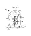
Figure 12. Figure 12 is a schematic block diagram a hand-held scanner implementing the battery compartment of the present invention.Scanner 1200 is any scanner such as the hand-held optical scanners available from Hewlett-Packard Company. -
Scanner 1200 has a bell-shapedhousing 1202 with aflat bottom surface 1216.Housing 1202 is designed to be easily grasped by a user. Generally, the user will holdhousing 102 and manually dragscanner 1200 over apaper 1204 to scan to printed information presented thereon.Scanner 1200 includes aCCD 1206 with navigational illumination lights 1214.Navigation illumination devices 1214 are high power drainage devices that generate infrared light that is used by an image processing and data storage device 1208 to track the location ofscanner 1200 onpaper 1204.CCD 1206 picks up the information on thepage 1204 and image processor 1208 reconstructs the image on the paper. Abattery compartment 1212 is configured to receive two 1.2 volt, AA dry cell batteries.Power supply 1210 coverts the 2.4 DC voltage to a 5 and 12 volts DC for use byscanner 1200. - Due to the high power consumption of
navigation illumination devices 1214,scanner 1200 draws approximately 5 amps. Without the present invention,scanner 1200 can deplete the two 1.2 volt batteries in 0.25-0.30 hours. A significant contributing factor to this rate of depletion is that the contact resistance between the two batteries is on the order of 0.2 ohms due to the presence of an insulating contaminant layer over the battery terminals. As such, 5 watts or 40% of the available 12 watts of power can be consumed overcoming the contact resistance. Implementing the present invention, however, reduces the contact resistance between abutting batteries to approximately 0.06 ohms; thereby reducing the power consumed overcoming the contact resistance to 1.5 watts. Similar scanners that operate at 2.5 amperes reduce the power losses at the terminal contacts from 1.25 watts to 0.38 watts, illustrating that devices with lower current requirements also benefit substantially from the present invention. - The present invention is related to commonly owned U.S. Patent Application entitled "CONICAL COILED SPRING CONTACT FOR MINIMIZING BATTERY-TO-DEVICE CONTACT RESISTANCE STEMMING FROM INSULATING CONTAMINANT LAYER ON SAME," naming as inventor Larry E. Maple, filed concurrently herewith.
- While various embodiments of the present invention have been described above, it should be understood that they have been presented by way of example only, and not limitation. For example, it should also be appreciated that although the noted dry cell and miniature batteries are described as being primary batteries, the present invention can also be used with secondary, or rechargeable batteries having the same or similar configuration. In the embodiments disclosed herein, the longitudinal axes of neighboring batteries both lie in the same imaginary plane. However, this need not be the case. That is, the longitudinal axes may not reside in the same plane. In other words, the longitudinal axes of the neighboring batteries may not only intersect at an angle in one plane or axis, but may also intersect at an angle in a second or third plane or axis. It should also be clear that the number of batteries is not restricted to those disclosed herein. For example, any number of
dry cell batteries 100 can be serially aligned, each having the relative arrangement with its neighbor as noted above. Thus, the breadth and scope of the present invention should not be limited by any of the above-described exemplary embodiments, but should be defined only in accordance with the following claims and their equivalents.
Claims (9)
- A battery compartment (800,900,1000,1100,1150) for storing at least two batteries (100, 200) in a serially aligned arrangement, characterised in that the battery compartment is configured to align the batteries with their respective longitudinal axes non-parallel so that the area of electrical contact between the terminals (106,108 and 206,208) of the batteries is less than the area of electrical contact between the terminals of the batteries (100,200) if aligned with said axes parallel.
- The battery compartment as claimed in claim 1, wherein the batteries (100, 200) comprise first and second dry cell batteries (100) and said area of electrical contact between the batteries results from contact between a terminal of said second battery (100) and an edge (112) of a positive terminal button (106) of said first battery (100).
- The battery compartment as claimed in claim 1, wherein the batteries (100,200) comprise first and second miniature batteries (200), and said area of electrical contact between the first and second miniature batteries results from contact between a terminal of said second battery (200) and an edge (212) of a terminal casing (206) of said first battery (200).
- The battery compartment as claimed in claim 2, wherein the first and second batteries (100,200) each have a casing (110,206) with positive and negative terminal surfaces (114, 214, 116, 216) on opposing ends of the batteries (100,200) and transected by the longitudinal battery axis (118, 218) substantially orthogonal to each terminal surface, wherein when installed, the longitudinal axes of the first and second batteries intersect each other.
- A battery compartment as claimed in any preceding claim, wherein the battery compartment is constructed and arranged to cause a terminal of the first battery to forcibly scrape against a terminal of the second battery.
- A battery compartment as claimed in any preceding claim, further comprising:positive and negative device contacts (600,700,820,908,1106,1156) installed in opposing ends of the battery compartment (800,900,1000,1100,1150) to contact a positive terminal (106,206) of a battery (100,200) last in the series of that at least one installed battery and a negative terminal (108,208) of a battery (100,200) first in the series of that at least one installed battery.
- A battery-powered device (1200) comprising:a battery compartment (800,900,1000,1100,1150,1212) as claimed in any preceding claim.
- A battery powered device (1200) comprising:a power consuming component; anda battery compartment as claimed in any of claims 1 to 6.
- A battery-powered device (1200) as claimed in claim 7 or 8, wherein said battery compartment (800,900,1000,1100,1150,1212) includes a negative device contact (502) which is a tab contact having an orthogonal surface vector (506) that intersects said longitudinal axis (118) of said battery (100) installed in said first series battery position.
Applications Claiming Priority (2)
| Application Number | Priority Date | Filing Date | Title |
|---|---|---|---|
| US838977 | 2001-04-20 | ||
| US09/838,977 US6641952B2 (en) | 2001-04-20 | 2001-04-20 | Battery arrangement for reducing battery terminal contact resistance stemming from insulating contaminant layer on same |
Publications (3)
| Publication Number | Publication Date |
|---|---|
| EP1255309A2 EP1255309A2 (en) | 2002-11-06 |
| EP1255309A3 EP1255309A3 (en) | 2004-07-14 |
| EP1255309B1 true EP1255309B1 (en) | 2008-06-11 |
Family
ID=25278550
Family Applications (1)
| Application Number | Title | Priority Date | Filing Date |
|---|---|---|---|
| EP02252821A Expired - Fee Related EP1255309B1 (en) | 2001-04-20 | 2002-04-22 | Battery arrangement for reducing battery terminal contact resistance |
Country Status (4)
| Country | Link |
|---|---|
| US (2) | US6641952B2 (en) |
| EP (1) | EP1255309B1 (en) |
| JP (1) | JP4109483B2 (en) |
| DE (1) | DE60227024D1 (en) |
Families Citing this family (10)
| Publication number | Priority date | Publication date | Assignee | Title |
|---|---|---|---|---|
| ATE489816T1 (en) * | 2001-10-12 | 2010-12-15 | Oticon As | HEARING AID, HEADPHONE OR SIMILAR DEVICE FOR DELIVERING A SOUND SIGNAL CLOSE TO THE EARTUM |
| US20050268472A1 (en) * | 2004-06-07 | 2005-12-08 | Bourilkov Jordan T | Shaving systems |
| US7090620B1 (en) * | 2005-05-16 | 2006-08-15 | Barlow Michael J | Battery charging assembly |
| DE102006005286B3 (en) * | 2006-02-06 | 2007-06-21 | Siemens Audiologische Technik Gmbh | Battery contacting device for hearing aid, has spiral contact, which is provided for contacting negative terminal of battery and is formed in partial section as induction coil through which current supplied by battery is derived |
| US7614907B2 (en) * | 2008-02-12 | 2009-11-10 | Chaojiong Zhang | Contact terminal with self-adjusting contact surface |
| EP2348561A1 (en) † | 2010-01-23 | 2011-07-27 | Braun GmbH | Battery contact spring |
| US8048552B1 (en) * | 2010-04-23 | 2011-11-01 | Psion Inc. | Battery module mount |
| EP2450995A1 (en) * | 2010-11-03 | 2012-05-09 | Nxp B.V. | Battery |
| US20140370345A1 (en) * | 2013-06-12 | 2014-12-18 | Motorola Mobility Llc | Segmented energy storage assembly |
| CN114039112B (en) * | 2021-11-26 | 2023-10-20 | 蜂巢能源科技(无锡)有限公司 | Battery cell SOC regulating and controlling device and regulating and controlling method thereof |
Family Cites Families (10)
| Publication number | Priority date | Publication date | Assignee | Title |
|---|---|---|---|---|
| US2896875A (en) | 1956-10-29 | 1959-07-28 | Willis E Reed | Motor drive fishing reel |
| JPS5159249U (en) * | 1974-11-01 | 1976-05-10 | ||
| US4871628A (en) * | 1988-10-14 | 1989-10-03 | Parker David H | Battery terminal post protector |
| US4993973A (en) | 1989-11-20 | 1991-02-19 | Motorola, Inc. | Battery contact |
| JP2624350B2 (en) | 1990-02-02 | 1997-06-25 | ウエスト電気株式会社 | Battery contacts |
| US5050053A (en) * | 1990-09-11 | 1991-09-17 | Mcdermott Kevin | Flashlight of selectable colors |
| US5432689A (en) * | 1993-01-13 | 1995-07-11 | Streamlight, Inc. | Flashlight and recharging system therefor |
| US5692919A (en) * | 1995-05-04 | 1997-12-02 | Motorola, Inc. | Rotatable contact carrier for interconnecting electrical devices |
| JP2001035473A (en) * | 1999-07-15 | 2001-02-09 | Toshiba Battery Co Ltd | Battery connecting member and vehicle |
| US6708887B1 (en) * | 2001-08-18 | 2004-03-23 | Gsl Solutions, Inc. | Detachable hand-held computer handle |
-
2001
- 2001-04-20 US US09/838,977 patent/US6641952B2/en not_active Expired - Lifetime
-
2002
- 2002-04-15 JP JP2002111851A patent/JP4109483B2/en not_active Expired - Fee Related
- 2002-04-22 DE DE60227024T patent/DE60227024D1/en not_active Expired - Fee Related
- 2002-04-22 EP EP02252821A patent/EP1255309B1/en not_active Expired - Fee Related
-
2003
- 2003-09-29 US US10/674,231 patent/US7351497B2/en not_active Expired - Lifetime
Also Published As
| Publication number | Publication date |
|---|---|
| US7351497B2 (en) | 2008-04-01 |
| US20040061477A1 (en) | 2004-04-01 |
| DE60227024D1 (en) | 2008-07-24 |
| JP4109483B2 (en) | 2008-07-02 |
| EP1255309A2 (en) | 2002-11-06 |
| EP1255309A3 (en) | 2004-07-14 |
| JP2002324530A (en) | 2002-11-08 |
| US20020155344A1 (en) | 2002-10-24 |
| US6641952B2 (en) | 2003-11-04 |
Similar Documents
| Publication | Publication Date | Title |
|---|---|---|
| US7491466B2 (en) | Battery with side terminal | |
| AU2004297627B2 (en) | Flashlight that can operate with alternative size batteries | |
| US6783390B2 (en) | Apparatus for preventing reverse polarity contact between a standard dry cell battery terminal and a battery compartment contact | |
| KR101122977B1 (en) | Dc adaptor and electronic apparatus using the same | |
| EP1255309B1 (en) | Battery arrangement for reducing battery terminal contact resistance | |
| US4399201A (en) | Battery casing | |
| EP1856748A2 (en) | Flat primary battery with gold plated terminal contacts | |
| US6635383B2 (en) | Conical coiled spring contact for minimizing battery-to-device contact resistance stemming form insulating contaminant layer on same | |
| KR20160141944A (en) | Rechageable battery | |
| TWI250680B (en) | Holding device for a cell | |
| JPS58152231A (en) | Camera capable of using dissimilar battery | |
| JP3269046B2 (en) | Electric equipment and battery pack | |
| WO2005034268A2 (en) | Batteries | |
| AU2011205191B2 (en) | Direct Current Power Supply | |
| JP2000188093A (en) | Replacement method for battery | |
| JP2001006645A (en) | Pack battery | |
| JP2002008607A (en) | Charging device |
Legal Events
| Date | Code | Title | Description |
|---|---|---|---|
| PUAI | Public reference made under article 153(3) epc to a published international application that has entered the european phase |
Free format text: ORIGINAL CODE: 0009012 |
|
| AK | Designated contracting states |
Kind code of ref document: A2 Designated state(s): AT BE CH CY DE DK ES FI FR GB GR IE IT LI LU MC NL PT SE TR |
|
| AX | Request for extension of the european patent |
Free format text: AL;LT;LV;MK;RO;SI |
|
| PUAL | Search report despatched |
Free format text: ORIGINAL CODE: 0009013 |
|
| AK | Designated contracting states |
Kind code of ref document: A3 Designated state(s): AT BE CH CY DE DK ES FI FR GB GR IE IT LI LU MC NL PT SE TR |
|
| AX | Request for extension of the european patent |
Extension state: AL LT LV MK RO SI |
|
| 17P | Request for examination filed |
Effective date: 20041213 |
|
| AKX | Designation fees paid |
Designated state(s): DE FR GB |
|
| GRAP | Despatch of communication of intention to grant a patent |
Free format text: ORIGINAL CODE: EPIDOSNIGR1 |
|
| GRAS | Grant fee paid |
Free format text: ORIGINAL CODE: EPIDOSNIGR3 |
|
| GRAA | (expected) grant |
Free format text: ORIGINAL CODE: 0009210 |
|
| AK | Designated contracting states |
Kind code of ref document: B1 Designated state(s): DE FR GB |
|
| REG | Reference to a national code |
Ref country code: GB Ref legal event code: FG4D |
|
| REF | Corresponds to: |
Ref document number: 60227024 Country of ref document: DE Date of ref document: 20080724 Kind code of ref document: P |
|
| PLBE | No opposition filed within time limit |
Free format text: ORIGINAL CODE: 0009261 |
|
| STAA | Information on the status of an ep patent application or granted ep patent |
Free format text: STATUS: NO OPPOSITION FILED WITHIN TIME LIMIT |
|
| 26N | No opposition filed |
Effective date: 20090312 |
|
| GBPC | Gb: european patent ceased through non-payment of renewal fee |
Effective date: 20090422 |
|
| REG | Reference to a national code |
Ref country code: FR Ref legal event code: ST Effective date: 20091231 |
|
| PG25 | Lapsed in a contracting state [announced via postgrant information from national office to epo] |
Ref country code: DE Free format text: LAPSE BECAUSE OF NON-PAYMENT OF DUE FEES Effective date: 20091103 |
|
| PG25 | Lapsed in a contracting state [announced via postgrant information from national office to epo] |
Ref country code: GB Free format text: LAPSE BECAUSE OF NON-PAYMENT OF DUE FEES Effective date: 20090422 Ref country code: FR Free format text: LAPSE BECAUSE OF NON-PAYMENT OF DUE FEES Effective date: 20091222 |