EP1255287A1 - Substrate processing method, and apparatus therefor - Google Patents
Substrate processing method, and apparatus therefor Download PDFInfo
- Publication number
- EP1255287A1 EP1255287A1 EP01936972A EP01936972A EP1255287A1 EP 1255287 A1 EP1255287 A1 EP 1255287A1 EP 01936972 A EP01936972 A EP 01936972A EP 01936972 A EP01936972 A EP 01936972A EP 1255287 A1 EP1255287 A1 EP 1255287A1
- Authority
- EP
- European Patent Office
- Prior art keywords
- substrate
- gas
- ozone
- treating
- containing gas
- Prior art date
- Legal status (The legal status is an assumption and is not a legal conclusion. Google has not performed a legal analysis and makes no representation as to the accuracy of the status listed.)
- Withdrawn
Links
Images


Classifications
-
- H—ELECTRICITY
- H10—SEMICONDUCTOR DEVICES; ELECTRIC SOLID-STATE DEVICES NOT OTHERWISE PROVIDED FOR
- H10P—GENERIC PROCESSES OR APPARATUS FOR THE MANUFACTURE OR TREATMENT OF DEVICES COVERED BY CLASS H10
- H10P50/00—Etching of wafers, substrates or parts of devices
-
- H—ELECTRICITY
- H10—SEMICONDUCTOR DEVICES; ELECTRIC SOLID-STATE DEVICES NOT OTHERWISE PROVIDED FOR
- H10P—GENERIC PROCESSES OR APPARATUS FOR THE MANUFACTURE OR TREATMENT OF DEVICES COVERED BY CLASS H10
- H10P70/00—Cleaning of wafers, substrates or parts of devices
- H10P70/20—Cleaning during device manufacture
- H10P70/27—Cleaning during device manufacture during, before or after processing of conductive materials, e.g. polysilicon or amorphous silicon layers
- H10P70/273—Cleaning during device manufacture during, before or after processing of conductive materials, e.g. polysilicon or amorphous silicon layers the processing being a delineation of conductive layers, e.g. by RIE
-
- B—PERFORMING OPERATIONS; TRANSPORTING
- B08—CLEANING
- B08B—CLEANING IN GENERAL; PREVENTION OF FOULING IN GENERAL
- B08B7/00—Cleaning by methods not provided for in a single other subclass or a single group in this subclass
-
- H—ELECTRICITY
- H10—SEMICONDUCTOR DEVICES; ELECTRIC SOLID-STATE DEVICES NOT OTHERWISE PROVIDED FOR
- H10P—GENERIC PROCESSES OR APPARATUS FOR THE MANUFACTURE OR TREATMENT OF DEVICES COVERED BY CLASS H10
- H10P50/00—Etching of wafers, substrates or parts of devices
- H10P50/20—Dry etching; Plasma etching; Reactive-ion etching
- H10P50/28—Dry etching; Plasma etching; Reactive-ion etching of insulating materials
- H10P50/286—Dry etching; Plasma etching; Reactive-ion etching of insulating materials of organic materials
- H10P50/287—Dry etching; Plasma etching; Reactive-ion etching of insulating materials of organic materials by chemical means
-
- H—ELECTRICITY
- H10—SEMICONDUCTOR DEVICES; ELECTRIC SOLID-STATE DEVICES NOT OTHERWISE PROVIDED FOR
- H10P—GENERIC PROCESSES OR APPARATUS FOR THE MANUFACTURE OR TREATMENT OF DEVICES COVERED BY CLASS H10
- H10P72/00—Handling or holding of wafers, substrates or devices during manufacture or treatment thereof
- H10P72/04—Apparatus for manufacture or treatment
- H10P72/0402—Apparatus for fluid treatment
- H10P72/0406—Apparatus for fluid treatment for cleaning followed by drying, rinsing, stripping, blasting or the like
- H10P72/0411—Apparatus for fluid treatment for cleaning followed by drying, rinsing, stripping, blasting or the like for wet cleaning or washing
- H10P72/0414—Apparatus for fluid treatment for cleaning followed by drying, rinsing, stripping, blasting or the like for wet cleaning or washing using mainly spraying means, e.g. nozzles
Definitions
- the present invention relates to a process for treating a substrate by removing, for example, a photoresist film and undesirable organic or inorganic compounds from the surface of an object to be treated in micro-processing steps including fabrication steps of a semiconductor such as IC and LCI; an LCD; and a printed substrate, and an apparatus therefor.
- a photoresist film and undesirable organic or inorganic compounds from the surface of an object to be treated in micro-processing steps including fabrication steps of a semiconductor such as IC and LCI; an LCD; and a printed substrate, and an apparatus therefor.
- a photosensitive organic polymer compound is applied to a semiconductor substrate of silicon or a glass substrate, and the substrate is exposed to ultraviolet ray having a specific wavelength through a photomask with a prescribed circuit pattern, followed by development using an aqueous alkaline solution to form a photoresist pattern on the substrate. Further, film formation by CVD, sputtering and the like; etching by a chemical agent or RIE (reactive ion etching); and diffusion by heating or ion-implantation of impurity elements is carried out. Then, the photoresist film on the substrate which has been subjected to a series of treatments is removed by means of chemical treatment. Generally, such a series of operations as applying a photoresist and removing the photoresist after various treatments is repeated more than once in the fabrication steps of LSI and the like.
- a variety of methods have been employed for removing a photoresist film. It is necessary to remove photoresist film completely since incomplete removal of the photoresist film may have bad influence on the subsequent steps. In particular, complete removal is required in recent cases where the integration degree of a semiconductor circuit is increased and the line width of a semiconductor circuit to be formed is made thin, since the residue of the photoresist film causes a more serious problem than in the case of a low integration degree circuit.
- a photoresist film is removed according to a wet method using a chemical solution or a dry method using oxygen plasma or the like.
- Japanese Unexamined Patent Publication No. 219926/1999 discloses a method for removing organic pollutant from a semiconductor substrate by mixed gas containing steam, ozone gas and a substance working as an OH radicalscavenger.
- solubility of ozone in a mixed layer of water and ozone formed on a surface of a substrate is restricted in a high temperature range, resulting in decrease of washing effect when the substrate temperature is increased for the purpose of improving treatment speed.
- the method of this patent publication is illustrated in Fig. 23 and comprises using a quartz tank 101 for storing a liquid and an ozone diffusion apparatus 102 positioned at the bottom of the tank.
- the wet ozone produced by diffusing ozone to a liquid is reacted on the object substrate 103 to be treated installed above the quartz tank.
- the mixed layer on the surface of the substrate can be made thin and an ozone component having a short life and high reactivity can easily reach the wafer surface, removal efficiency approximating 100 %.
- a treatment chamber 110 comprises a substrate setting stand 111, a substrate 112, a gas dispersion plate 118, holes 119 and an ultrapure water supply nozzle 121.
- an ozone decomposition apparatus 120 through a gas discharge tube 113, an oxygen storage tank 115, an ozone generator 114 and a gas contact apparatus 116 through an ozone-containing gas supply tube 117.
- ozone-containing gas is wetted, for example, by passing the gas through ultrapure water, the resulting ozone-containing gas is introduced to the surface of the substrate 112 to be treated.
- the surface of the substrate is gradually wetted by the wet ozone-supply gas and a thin film of water is formed on the substrate surface to make the removal of an organic film possible without heating the substrate.
- Japanese Unexamined Patent Publication No. 133535/1988 discloses a method which comprises washing an object to be washed with a washing solution which shows acidity by water addition and then diluting the washing solution without increasing the hydrogen ion concentration. Dilution with a buffer solution such as a phosphoric acid solution prevents generation of strong acid and prevents aluminum wiring from corroding and disconnecting.
- Japanese Unexamined Patent Publication No. 166724/1991 discloses a method which comprises incinerating a photoresist formed on a semiconductor substrate either with oxygen plasma or in ozone atmosphere and then washing with pure water. In this case, since washing is carried out with water having a high purity and water is discharged immediately, the surface of the substrate can be kept neutral even if an acid is produced attributed to residual chlorine. Corrosion of an aluminum alloy, which is a wiring material, is prevented according to this method.
- Japanese Unexamined Patent Publication No. 109686/1993 discloses a cleaning method capable of removing organic substances and adhering substances on the wafer surface by supplying steam, ozone gas and ammonia gas.
- composition of the chemical solution is changed by evaporation or reaction and washing effect is decreased with time. According to this method, stable washing effect can be obtained by using ozone as an oxidizer in place of hydrogen peroxide.
- composition ratio of ammonia gas : ozone gas : steam is the optimum if it is (1/20 to 1/5) : (1/6 to 1/4) : 1.
- Fig. 25 illustrates this method in which acetic acid 122 is supplied to a tank 123 for rinsing and supplied to a wafer 125 through a quartz wool sheet 124 and ozone 127 is supplied from an ozone buffer 126.
- a substrate 125 coated with 1 ⁇ m-thick resist is immersed in acetic acid of room temperature (purity: 99.7 %) saturated with 200 mg/L of ozone gas and the substrate is immediately pulled out.
- a 50 ⁇ m-thick liquid film is fed to the surface of the substrate through the glass wool 124 and the resist is completely peeled within a minute.
- the surface of a substrate is kept neutral by introducing an alkaline substance in the same amount as that of the acidic substance into the system.
- the wiring corrosion can be prevented by introducing an alkaline substance in the same amount as that of the acidic substance produced by the oxidation decomposition of organic pollutant by ozone.
- ammonia and ozone gas as disclosed in Japanese Unexamined Patent Publication No. 109686/1993, attention is paid only to the ratio of the oxidizer (ozone) to the reducing agent (ammonia) contained in the washing gas, and therefore excess ammonia is introduced as compared with the amount of the acidic substance produced by oxidation decomposition of organic pollutant by ozone.
- An object of the present invention is to provide a method of treating a substrate and an apparatus therefor capable of controlling pH alteration on the surface of the substrate caused by acidic substance produced by oxidation decomposition of organic pollutant and thus preventing corrosion of wiring in the removal of organic pollutant by wet ozone gas from a substrate comprising metal having low acid resistance or alkali resistance as a wiring material.
- the first process for treating a substrate of the present invention is a process for treating a substrate by removing organic pollutant on the surface of the substrate using mixed gas of wet-ozone containing gas wetted by steam and basic gas, wherein a supply speed of basic gas molecule is at most 100 times as high as the production speed of molecule of acidic substance produced by oxidation reaction of the organic pollutant.
- the second process for treating a substrate of the present invention is that a volatile substance is introduced as the basic gas in the above process for treating a substrate.
- the third process for treating a substrate of the present invention is that ammonia gas is used as the volatile substance in the second process of the present invention.
- the fourth process for treating a substrate of the present invention is that the ammonia gas passed through a saturated aqueous solution of ammonia is used as the ammonia gas in the third process of the present invention.
- the fifth process for treating a substrate of the present invention is that a non-volatile substance is used as the basic gas in the first process of the present invention.
- the sixth process for treating a substrate of the present invention is that TMAH (tetramethylammonium hydroxide) is used as the non-volatile substance in the fifth process of the present invention.
- TMAH tetramethylammonium hydroxide
- the seventh process for treating a substrate of the present invention is that the mixing duration from the mixing of the basic gas molecule and the wet ozone-containing gas to the arrival of the gas mixture at the substrate to be treated is controlled to at most 10 seconds in the first process of the present invention.
- the eighth process for treating a substrate of the present invention comprises removing organic pollutant on the surface of the substrate using wet ozone-containing gas wetted by a treatment liquid, wherein a solvent capable of preventing ionization of acidic substance produced by the oxidation reaction of the organic pollutant is used as the treatment liquid.
- the ninth process for treating a substrate of the present invention is that a solvent having low reactivity to ozone is used as the treatment liquid in the eighth process of the present invention.
- the tenth process for treating a substrate of the present invention is that acetic acid or acetone is used as the solvent having low reactivity to ozone in the ninth process of the present invention.
- the eleventh process for treating a substrate of the present invention is that the supply speed of molecule of the solvent is controlled to at most 150 times as high as the production speed of molecule of the acidic substance produced by the oxidation reaction of the organic pollutant in the eighth process of the present invention.
- the twelfth process for treating a substrate of the present invention is a process for treating a substrate by removing organic pollutant substance on the surface of the substrate using wet ozone-containing gas wetted by a treatment liquid, wherein voltage of wired metal previously formed on the substrate is adjusted.
- the first apparatus for treating a substrate of the present invention comprises a substrate heating means for keeping a substrate at temperature higher than room temperature, a wetting means for obtaining wet ozone-containing gas by wetting, with a treatment liquid, ozone-containing gas generated by an ozone generator, a supplying means for supplying the wet ozone-containing gas to substance to be treated on the surface of the substrate, a gas sending tube for connecting the wetting means and the supplying means, a gas heating means for heating each of the wetting means, the supplying means and the gas sending tube to temperature equal to or higher than that of the substrate, and a supplying means for supplying supplying supplying a basic gas-containing gas to the substance to be treated on the surface of the substrate.
- the second apparatus for treating a substrate of the present invention further comprises a removing means for removing undesirable impurities generated from the ozone generator in the first apparatus for treating a substrate of the present invention between the ozone generator and the wetting means for wetting the ozone-containing gas.
- the third apparatus for treating a substrate of the present invention comprises a substrate heating means for keeping a substrate at temperature higher than room temperature, a wetting means for obtaining wet ozone-containing gas by wetting, with a treatment liquid, ozone-containing gas generated by an ozone generator, a supplying means for supplying the wet ozone-containing gas to substance to be treated on the surface of the substrate, a gas sending tube for connecting the wetting means and the supplying means, a gas heating means for heating each of the wetting means, the supplying means and the gas sending tube to temperature equal to or higher than that of the substrate and a controlling means capable of adjusting the potential of a metal wiring previously formed on the substrate.
- Fig. 1 is a view showing the constitution of an apparatus for treating a substrate according to Embodiment 1 of the present invention.
- a substrate 2 disposed in a treatment chamber 1 is fixed on a plate heater 4 attached to a substrate stand 3.
- a header 5 to evenly supply wet ozone-containing gas to the surface of the substrate to be treated by controlling the gas flow is installed above the substrate 2 and is provided with a mechanism capable of heating to at least room temperature if necessary.
- the facilities for generating the ozone-containing gas comprises an ozone gas generator 6, a humidifier 7 for humidifying the ozone gas, a gas sending tube 8b for introducing the humidified ozone gas into the treatment chamber 1, a ribbon heater 9 for preventing condensation of steam in the gas sending tube 8b, a pure water tank 10 for washing the substrate 2 after ozone treatment, a pump 11 for sending washing water, a gas discharge tube 12 for discharging the ozone-containing gas and a gas discharge adjustment valve 13 for adjusting the discharge amount of the ozone-containing gas.
- a chemical substance to be added for preventing wiring corrosion is generated in an additive gas generator 18 and the gas generator 18 is connected to the treatment chamber 1 through the gas sending tubes 8a and 8c and can be heated by the ribbon heater 9 if necessary.
- a mass flow controller is used to control the flow rate of an additive gas.
- the wet ozone-containing gas and the additive gas are previously mixed at the point d mm before the mixed gas supply port which is the lower end of the header 5, and then introduced to the object surface to be treated of the substrate 2 through the gas sending tube 8c having an inner diameter of 6 mm.
- a temperature measurement apparatus 19 is installed at the supply port of the header 5 to measure the gas temperature.
- an example to be employed is an apparatus with a constitution as illustrated in Fig. 14 such that an ozone-containing gas is passed through a treatment liquid 16 stored in a bubbling bottle 17 and a heater 15 is installed to heat the treatment liquid 16 to at least room temperature.
- a pressure tank 20 filled with reactive gas at a high pressure as illustrated in Fig. 15 is employed and the flow rate is controlled by a mass flow controller 21.
- those to be exposed to the wet ozone gas are made of a material having high ozone resistance, such as quartz glass or a fluororesin.
- An ozone gas decomposition tower 14 is installed in the rear stage of the gas discharge tube 12 and the remaining ozone gas is completely decomposed and discharged as oxygen gas.
- the substrate 2 is heated to a prescribed temperature by the plate heater 4. Further, the treatment liquid 16 of the humidifier 7 (Fig. 14), the gas sending tube 8a, the gas sending tube 8b, the gas sending tube 8c and the header 5 are also previously heated and stabilized at a prescribed temperature.
- the ozone-containing gas is passed through the humidifier 7 and wet ozone-containing gas accompanied with humidity is supplied to the object to be treated on the substrate 2.
- additive gas generation from the additive gas generator 18 is started and the flow rate is adjusted by the mass flow controller to supply the gas to the substrate 2.
- humidity of the ozone-containing gas in the humidifier 7 is equivalent to the saturated steam at the treatment liquid temperature and the amount of vapor within the ozone-containing gas can be controlled by changing temperature of the treatment liquid.
- Embodiment 1 will be described in detail with reference to examples.
- a positive-type photoresist (TFR-B available from Tokyo Ohka Kogyo Co., Ltd.) was applied to a surface-cleaned substrate (a 0.7 mm-thick glass substrate on which a 200 nm-thick Al film was already formed) by a spin coater, pre-baking was carried out at 120°C for 3 minutes to form a photoresist film of 1,450 nm thick as an object to be treated. Further, using a photomask with hole patterns having a diameter of 10 ⁇ m at every 0.1 mm, exposure treatment and development treatment were carried out to form a large number of holes having a diameter of 10 ⁇ m and a depth of 1,450 nm at 0.1 mm intervals.
- TFR-B available from Tokyo Ohka Kogyo Co., Ltd.
- the substrate 2 having a size of 200 mm ⁇ 200 mm was set upward on the plate heater 4 in the treatment chamber 1 and heated to 73°C.
- the gas sending tube 8a, the gas sending tube 8b, the gas sending tube 8c and the header 5 were heated to 90°C and after the respective temperature levels were stabilized, wet ozone-containing gas (ozone concentration: 200 g/Nm 3 ) which had been passed through pure water heated to 90°C and humidified by the humidifier 7 was supplied at a flow rate of 5,000 cc/minute.
- the humidity of the wet ozone-containing gas was adjusted to be the saturated steam concentration at 90°C.
- Ammonia gas was used as a basic gas added to prevent wiring corrosion while the gas flow rate was adjusted by a mass flow controller.
- Ammonia gas flow rate was changed from 0 to 7,000 cc/minute and the Al film thickness after the complete removal of the photoresist film by wet ozone-containing gas and ammonia gas was measured by a stylus type film thickness profilometer.
- the Al film thickness was gradually decreased at a flow rate of at least 1,500 cc/minute, and the surface of the substrate 2 became alkaline with pH of at least 9 and the Al film was partially dissolved at a flow rate of 2,000 cc/minute.
- the time required for complete removal the photoresist film is shown as a relative value based on the time of using no ammonia gas as 1. It is found that the removal speed of the photoresist film was increased when the flow rate of ammonia gas was in a range of 40 to 1,500 cc/minute in which the Al film dissolution was prevented. Further, when the flow rate of ammonia gas was 2,000 cc/minute, it took as long as twice the time for complete removal.
- the measurement results by the temperature measurement apparatus 19 installed in the header supply port are shown in Fig. 4.
- the apparatus indicated at 90°C, which was the set value of the gas temperature.
- the gas temperature was gradually increased and reached 260°C when the flow rate of ammonia gas was 6,000 cc/minute.
- the cause is supposed to be heat generation due to the interaction of ammonia and ozone. Since ammonia gas was added at 6,000 cc/minute while ozone gas was added at 5,000 cc/minute, the ammonia concentration becomes 55 %.
- an ozone-resistant material is desirable for the treatment chamber 1 and the tubes.
- a fluororesin generally has chemical resistance and ozone resistance, but the highest temperature for continuous use is relatively low: 260°C in the case of PTFE; 260°C in the case of PFA; and 200°C in the case of FEP. Since PTFE was used in this Example, it is necessary to adjust the gas temperature to at most 260°C. Consequently, the flow rate of the ammonia gas to be added is desirably at most 6,000 cc/minute.
- the amount of ammonia gas supply is investigated.
- the photoresist film having an initial film thickness of 1,450 nm (a total photoresist weight on the substrate of 200 mm ⁇ 200 mm is 0.0324 g) was completely removed by carrying out the 1-minute treatment twice.
- the necessary amount of ammonia gas can be described as the following equation using the degree of ionization of ammonia and the degree of ionization of acetic acid in an aqueous solution.
- (the necessary amount of ammonia gas) (the production speed of acetic acid) ⁇ (the degree of ionization of acetic acid + the degree of ionization of ammonia)
- the Al film dissolution was prevented in an ammonia gas flow rate range of as wide as 40 to 2,000 cc/minute. It is supposed that the reason for the successful prevention of dissolution in spite of adding ammonia in an amount of about thirty-three times the theoretical necessary amount for neutralization of 60 cc/minute is that part of the introduced ammonia was oxidized and consumed by ozone owing to the interaction between ozone and ammonia.
- the flow rate of ammonia gas is in the range of 40 to 1,500 cc/minute, the Al film dissolution was completely prevented since the pH on the substrate was controlled to pH 4 to 9 owing to the interaction between ozone, ammonia and acidic substance.
- ammonia was added for the purpose of neutralizing the acidic substance produced along with the oxidation of the resist film. Since the theoretical value of the ammonia gas flow rate necessary to neutralize the produced acidic substance is 60 cc/minute, it is required to adjust the ammonia gas flow rate to 6,000 cc/minute at highest in order to use PTFE safely as a tube material at temperature of at most 260°C.
- the production speed of the acidic substance molecule produced along with the resist decomposition is equal to the supply speed of ammonia molecule contained in the ammonia gas supplied at a flow rate of 60 cc/min
- the supply speed of the ammonia molecule at the above maximum ammonia gas flow rate of 6,000 cc/minute is 100 times as high as the production speed of the acidic substance molecule mentioned above.
- a process for treating a substrate it is preferable to control the decreasing amount of an Al film to at most 100 nm from a practical point of view. This is because there arise defects in properties of metal as wiring when the Al film is decreased by more than 100 nm. Accordingly, from Fig. 2, it is preferable to adjust the flow rate of ammonia gas to be at most 2,000 cc/minute and adjust the supply speed of ammonia gas to be at most thirty-three times as high as the production speed of the acidic substance.
- ammonia gas was employed as the basic gas, but pyridine, ethylamine, dimethylamine, tetramethylamine, tributylamine, dibutylamine, triethylamine, aniline and the like are also effective.
- pyridine, ethylamine, dimethylamine, tetramethylamine, tributylamine, dibutylamine, triethylamine, aniline and the like are also effective.
- Kagaku Binran (Chemical Handbook) Basic (3rd edition) II p. 343, tetramethylamine has ionization coefficient of 3.2 and ionization degree of at least 10 times as high as that of ammonia. Therefore, the amount of basic gas necessary to neutralize the acidic substance derived from the photoresist film is smaller in case of tetramethylamine than in case of ammonia.
- amines such as tetramethylamine mentioned above can be supplied by the method of Example 1.
- a basic gas other than ammonia gas can neutralize the acidic substance produced by oxidation of the resist film and prevent the Al film dissolution.
- a volatile basic gas such as tetramethylamine or ammonia can be supplied in a state of gas as an additive gas generation method. Therefore, adjustment of the amount becomes easier, making it possible to prevent an Al film from dissolving further efficiently.
- Example 2 is one in which the flow rate of ammonia gas in Example 1 was fixed to 60 cc/minute and the flow rate of ozone gas in Example 1 was adjusted to 5,000 cc/minute.
- the distance d hereinafter sometimes referred to as "mixing distance" for short
- the distance was set to 100 mm in Example 1.
- a series of the steps of 1-minute substrate treatment and the rinsing with pure water was repeated until the photoresist film on the substrate 2 was completely removed in the same manner as in Example 1.
- the mixing distance d of ammonia gas and wet ozone-containing gas was changed in a range of 10 mm to 20 m and the Al film thickness after the complete removal of the photoresist by wet ozone-containing gas and ammonia gas was measured using a stylus type film thickness profilometer.
- Example 2 The results of Example 2 are shown in Fig. 5.
- the time from the mixing of wet ozone-containing gas and ammonia gas to the supply is defined as mixing time t M .
- the mixing time is calculated from the mixing distance and shown in the x-axis.
- the pH on the surface of the substrate 2 measured before rinsing with pure water is shown together with the Al film thickness measured value.
- t M 50 msec
- the mixing time was at least 1 second, the pH on the substrate became at most pH 4 and the Al film was partly dissolved.
- complete removal time time dependency (hereinafter sometimes referred to as "complete removal time") which means the time required for complete removal of the photoresist film completely (shown as relative values based on the complete removal time of the case without ammonia gas introduction as 1 in the same manner as in Fig. 3).
- complete removal time was 5 msec
- the complete removal time was about 0.8 which was similar to that in the case where the mixing time t M was 50 msec.
- the mixing time t M was at least 2 sec, the complete removal time became twice longer than that in the case where no ammonia gas was introduced. Further, it took four times longer when the mixing time was 10 sec.
- the mixing time is long, interaction time of ozone and ammonia is long, and therefore, heat is generated due to reaction, resulting in increase of the gas temperature.
- the gas temperature was increased and reached 260°C when the mixing time was 10 sec.
- the mixing time is desirably 10 sec at longest.
- Example 2 The results of Example 2 can be explained as follows.
- the wet ozone-containing gas caused chemical interaction between ammonia gas and it is possible that ozone and ammonia are consumed owing to the interaction when the mixing distance is too long. More specifically, when the flow rate of ammonia gas is 60 cc/minute and the mixing time t M is at most 1 sec (the mixing distance is at most 2 m), the interaction between ozone and ammonia is small and affects neither the Al film corrosion prevention effect nor the photoresist removal speed. However, when the mixing time t M is at least 1 sec, the interaction duration of ammonia gas and ozone gas becomes long and ammonium nitrate is produced. That is, ammonia and ozone are consumed uselessly.
- a photoresist film 34 is oxidized to produce acidic substance by wet ozone-containing gas comprising water molecules 31 and ozone molecules 32 supplied from the upper side of the substrate 2.
- the acidic substance is ionized in a thin water film 33 formed on the photoresist film to produce hydrogen ions 36.
- the photoresist film 34 has holes orderly formed at every 0.1 mm and wiring metal 35 previously formed under the photoresist film 34 is exposed.
- the hydrogen ion 36 produced from the above acidic substance affects wiring metal 35 through the holes formed in the photoresist film 34 to promote corrosion.
- Examples 1 and 2 can be explained with reference to Fig. 12(b).
- Wet ozone-containing gas comprising water molecules 31 and ozone molecules 32 together with ammonia molecules 37 are supplied on the substrate 2 with interaction 39 proceeding.
- acidic substance is produced in a thin water film 33 by the oxidation reaction of the photoresist film 34 with ozone gas, they are successively neutralized by ammonia gas supplied simultaneously and therefore the amount of hydrogen ions is not increased. Therefore, it is possible to prevent the corrosion of the orderly exposed wiring metal film 35.
- the interaction (the mixing time) 39 of the gas mixture until the gas mixture is supplied to the substrate 2 is long, there is a possibility of wasteful consumption before reaching the substrate.
- Example 3 is one in which the substrate temperature in Example 1 was adjusted to 75°C.
- the pressure tank 20 (Fig. 15) filled with a reactive gas at a high pressure was employed as the additive gas generator 18 (Fig. 1), whereas a humidifier is installed in the rear of a pressure tank 20 in this Example as shown in Fig. 16.
- the humidifier the one employed has a constitution such that ammonia gas is passed through a saturated aqueous solution of ammonia 22 stored in a bubbling tank 23 and is provided with a heater 15 for heating the saturated aqueous solution of ammonia 22 to at least room temperature.
- Example 3 the temperature of the saturated aqueous solution of ammonia 22 was changed and a series of the steps of 1-minute substrate treatment and the rinsing with pure water was repeated until the photoresist film on the substrate 2 was completely removed in the same manner as in Example 1.
- the temperature of the aqueous ammonia solution was changed in a range of 1 to 90°C, and the time required for complete removal the photoresist by wet ozone-containing gas and ammonia gas was measured.
- the gas sending tube 8a (Fig. 1) to introduce ammonia gas was adjusted to be at 95°C in order to prevent dew formation inside the tube.
- Fig. 7 shows time dependency (hereinafter sometimes referred to as "complete removal time") which means the time required for complete removal of the photoresist film completely.
- the results are shown in relative values based on the time in case of the aqueous ammonia temperature of 1°C as 1. With the increase of the humidity accompanying ammonia gas, the complete removal time of the photoresist film was shortened by 30 to 40%.
- ammonium hydroxide comprises ammonium ion
- ammonium hydroxide is supposed to have lower reactivity with ozone than ammonia.
- Example 3 the effect of adding ammonia gas was observed even in the case of the mixing time of as long as 10 sec. This is because ammonia was converted to ammonium hydroxide (NH 4 OH) 38 by passing ammonia through saturated ammonia and the interaction after mixing wet ozone-containing gas and wet ammonia gas was prevented as shown in the schematic illustration of Fig. 13.
- ammonia was converted to ammonium hydroxide (NH 4 OH) 38 by passing ammonia through saturated ammonia and the interaction after mixing wet ozone-containing gas and wet ammonia gas was prevented as shown in the schematic illustration of Fig. 13.
- Example 4 experiment was carried out as to the case of using an aqueous solution containing TMAH (tetramethylammonium hydroxide) (hereinafter sometimes referred to as "TMAH aqueous solution” for short) as the basic substance which was added in Example 1 to prevent wiring corrosion.
- TMAH tetramethylammonium hydroxide
- a humidifier equipped with an ultrasonic oscillator is employed. As shown in Fig.
- the humidifier employed has a constitution such that nitrogen gas is passed through the TMAH aqueous solution 25 stored in a bubbling tank 26 and an ultrasonic oscillator 24 is installed thereto in order to generate finely atomized vapor from the TMAH aqueous solution.
- the flow rate of nitrogen gas supplied from a nitrogen gas bomb 27 is controlled by a mass flow controller 21.
- a series of the steps of 1-minute substrate treatment and the rinsing with pure water was repeated until the photoresist film on the substrate 2 (Fig. 1) was completely removed in the same manner as in Example 1.
- the TMAH concentration in the TMAH aqueous solution was adjusted to 0.28 mol/L and atomizing power of the ultrasonic oscillator 24 was changed. Then, the Al film thickness after removing the photoresist completely by wet ozone-containing gas and TMAH-aqueous-solution containing nitrogen gas was measured by a stylus type film thickness profilometer.
- Example 4 The results of Example 4 are shown in Fig. 8.
- the pH on the surface of the substrate 2 measured before rinsing with pure water is shown together with the Al film thickness measured values.
- Fig. 8 show that the pH on the substrate was increased (the acidity was decreased) with the increase of the atomized amount of the TMAH aqueous solution.
- the atomized amount of the TMAH aqueous solution was 4 to 40 (9.5 g/minute to 95 g/minute)
- the atomized amount of the TMAH aqueous solution and the amount of actual introduction have such a relationship as shown in Table 1.
- Sprayed amount of aqueous TMAH solution Actual amount of introduction (g/minute) 4 9.5 50 119 200 475
- the gas temperature was gradually increased and reached 260°C when the atomized amount was 400 (950 g/min).
- the cause is supposed to be heat generation due to the interaction between the TMAH aqueous solution and ozone.
- an ozone-resistant material is desirable for the treatment chamber 1 or the tubes.
- a fluororesin generally has chemical resistance and ozone resistance, but the highest temperature for continuous use is relatively low: 260°C in the case of PTFE; 260°C in the case of PFA; and 200°C in the case of FEP. Since PTFE was used in this Example, it is necessary to adjust the gas temperature to at most 260°C. Therefore, the flow rate of the ammonia gas to be added is desirably at most 400 (950 g/min) in the atomized amount.
- the Al film dissolution was prevented in an atomized amount of as wide as 4 to 40 (9.5 g/min to 95 g/min). It is supposed that the reason for the successful prevention of dissolution in spite of adding TMAH in an amount of about ten times the theoretical necessary amount for neutralization is that part of the introduced TMAH was oxidized and consumed by ozone owing to the interaction between ozone and TMAH. In an atomized amount range of 4 to 40, dissolution of the Al film was completely prevented since the pH on the substrate was controlled to pH 4 to 9 owing to the interaction between ozone, TMAH and acidic substance.
- TMAH was added for the purpose of neutralizing the acidic substance produced by the resist film oxidation. Since the theoretical value of the atomized amount of TMAH necessary for neutralizing the produced acidic substance is 9.5 g/minute, it is required to control the atomized amount of the TMAH to at most 950 g/minute in order to use PTFE safely as a tube material at a temperature of at most 260°C.
- the production speed of the acidic substance produced along with the resist decomposition is equal to the supply speed of TMAH molecule in case of atomized amount of 9.5 g/minute. Therefore, the supply speed of TMAH molecule in case of the maximum atomized amount of TMAH of 950 g/minute is 100 times as much as the production speed of the above acidic substance.
- the TMAH aqueous solution was used as the basic substance to prevent wiring corrosion.
- hydroxide such as sodium hydroxide or potassium hydroxide, aqueous ammonia and the like are also effective.
- the spraying amount of the aqueous basic solution necessary to neutralize the acidic substance derived from a photoresist film can be smaller in case of using an aqueous hydroxide solution than in case of using the TMAH aqueous solution. Since hydroxide mentioned above is not volatile, hydroxide is supplied to the substrate to be treated by spraying the same according to the method described in this Example.
- Example 5 experiment was carried out as to the case of using an aqueous ammonia as the alkaline substance which was used in Example 1 to prevent wiring corrosion.
- the ammonia concentration in the aqueous ammonia was adjusted to 6.7 ⁇ 10 -1 mol/L and the atomizing power of the ultrasonic oscillator 24 was changed, and then, A1 film thickness after complete removal of the photoresist by wet ozone-containing gas and aqueous ammonia-containing nitrogen gas was measured using a stylus type film thickness profilometer.
- a positive-type photoresist (TFR-B manufactured by Tokyo Ohka Kogyo Co., Ltd.) was applied to a surface-cleaned substrate 2 (a 0.7 mm-thick glass substrate in which a 200 nm-thick Al film was already formed) by a spin coater, post-baking was carried out at 120°C for 3 minutes to form a photoresist film of 1,450 nm thick as an object to be treated. Further, using a photomask with hole patterns having a diameter of 10 ⁇ m at every 0.1 mm, exposure treatment and development treatment were carried out to form a large number of holes having a diameter of 10 ⁇ m and a depth of 1,450 nm at 0.1 mm intervals.
- the Al film existing under the photoresist film was completely exposed.
- the substrate 2 having a size of 200 mm ⁇ 200 mm was placed on the plate heater in the treatment chamber 1 with the photoresist film upward and heated to 73°C.
- the gas sending tube 8a, the gas sending tube 8b, the gas sending tube 8c and the header were heated to 90°C and after the respective temperature levels were stabilized, gas containing ozone and acetic acid (ozone concentration: 200 g/Nm 3 ) which had been passed through acetic acid heated to 90°C and humidified by the humidifier 7 was supplied at a flow rate of 3,000 cc/minute.
- the vapor pressure of acetic acid in the gas containing wet ozone and acetic acid (hereinafter sometimes referred to as acetic acid- and ozone-containing gas) was adjusted to the saturated vapor pressure at 90°C.
- Example 1 When the time for the complete removal by the wet ozone-containing gas at 90°C in Example 1 was set to be 1, the time for the complete removal by the acetic acid- and ozone-containing gas was shortened to be 0.5 to 0.6.
- acetic acid is stable to ozone since acetic acid is the final product of ozonization reaction.
- ozone and the acetic acid vapor showed no interaction even if the time from mixing ozone with acetic acid to the arrival of the mixture at the gas supply port of the header was about 1 second. It is thought that results as shown in Fig. 10 were obtained for this reason.
- the dissociation constant pKa of acidic substance is a logarithm of the dissociation ratio Ka of the acidic substance HA to hydrogen ion H + and the anion A - .
- Ka (hydrogen ion H + concentration) ⁇ (the anion A - concentration) + (acidic substance concentration HA)
- the substances produced by the oxidation of the photoresist film are mainly acetic acid. Therefore, as to the degree of ionization of the acidic substance produced by oxidation decomposition of the photoresist, it is possible to refer to the dissociation constant of acetic acid to acetic acid itself, which is 14.45 shown in Table 3.
- the amount of acetic acid vapor to be introduced to the treatment tank is about 6.4 mg/minute when the temperature of the acetic acid solution is 90°C.
- an acetic acid liquid film having a thickness of 0.064 mg/ (cm 2 ⁇ min) is to be formed per unit surface area of the photoresist film.
- waste liquid from a large number of apparatus is generally treated at one time, but it is also desirable that the TOC amount in waste liquid from each piece of apparatus is kept to at most the value in compliance with the environmental standard. Accordingly, it is necessary to control the amount of acetic acid to be introduced into the treatment process to at most 150 times as high as the production speed of the substances produced attributed to the decomposition of the photoresist.
- Example 6 acetic acid was used to prevent the ionization of the substances on the substrate, which is generated by oxidation of the photoresist film. But in this Example, experiments were carried out using acetone as a solvent. Since the boiling point of acetone is 51°C, the substrate was heated to 40°C. The gas sending tube 8a, the gas sending tube 8b, the gas sending tube 8c and the header 5 were heated to 50°C. After the respective temperature levels were stabilized, acetone and ozone-containing gas (ozone concentration: 200 g/Nm 3 ) which had been passed through acetone heated to 50°C and humidified by the humidifier 7 was supplied at a flow rate of 3,000 cc/minute. The vapor pressure of acetone in gas containing acetone vapor and ozone (hereinafter sometimes referred to as acetone- and ozone-containing gas) was adjusted to the saturated vapor pressure at 50°C.
- acetone- and ozone-containing gas was adjusted to the saturated vapor pressure
- the time for the complete removal by the wet ozone-containing gas at 90°C in Example 1 was set to be 1, the time for the complete removal by the acetone- and ozone-containing gas was shortened to be 0.7 to 0.8.
- Examples 6 and 7 a solvent which prevents the ionization of the substances generated by oxidation of photoresist film on the substrate was used. However, when such a solvent has reactivity to ozone, the resist removal property was deteriorated owing to the consumption of ozone.
- Example 5 chloroform or carbon tetrachloride was used in place of acetic acid or acetone.
- the time for complete removal is shown in Table 5 (the time for complete removal of the resist film by acetic acid- and ozone-containing gas in Example 6 was set to be 1).
- a solvent having low reactivity with ozone is preferable as a solvent to be introduced to prevent the ionization of acidic substance produced by resist oxidation decomposition.
- Examples 1 to 8 disclosed methods for treating a substrate in case of using A1 as the wiring material of the substrate. Since A1 can form a stable oxide in a pH range of 4 to 9 as described in the section of the background art, the pH was adjusted to the range of 4 to 9 by controlling flow rate of the additive gas and the like in Examples 1 to 5. However, since different metals have different stable regions, it is necessary to arrange such a condition as the amount of additive gas in consideration of those stable regions.
- Table 6 shows the pH ranges in which various metals can form stable oxide when exposed to ozone-containing water.
- metal pH range aluminium 4 ⁇ 9 copper 7 ⁇ 13 nickel at least 7 tungsten at most 4 iron at least 2 zinc 8 ⁇ 11 indium 5 ⁇ 11 titanium all magnesium at least 12
- the decomposed photoresist film was removed by supplying pure water of 55°C to the substrate 2 at a flow rate of 3,000 cc/minute. A series of the steps of 1-minute substrate treatment and the rinsing with pure water was repeated until the photoresist film on the substrate 2 was completely removed.
- the flow rate of ammonia gas was changed and the film thickness of various metals after the complete removal of the photoresist by wet ozone-containing gas and ammonia gas was measured using a stylus type film thickness profilometer. Further, after the treatment with wet ozone-containing gas, the pH on the surface of the substrate was measured just before the rinsing step with pure water.
- the pH on the surface of the substrate after the substrate treatment varied in accordance with the change in the ammonia gas flow rate, and corrosion was prevented when the pH entered the stable range of each metal.
- the ammonia flow rate necessary for the stabilization was about 2,000 cc/minute, which was the highest, because magnesium is stabilized in an alkaline state of at least pH 12.
- the production speed of the acidic substance molecule produced by oxidation of the photoresist film is equal to the supply speed of the ammonia molecule supplied at an ammonia gas flow rate of 60 cc/min
- the supply speed of ammonia molecule at the above flow rate of 2,000 cc/minute is about 33 times as high as the production speed of the acidic substance molecule.
- the flow rate of ammonia gas was at least 2,000 cc/minute for magnesium, at most 1,750 cc/minute for indium, 1,000 cc/minute for tungsten, 1,750 cc/minute for zinc and 1,500 cc/minute for copper.
- Embodiment 1 which mainly describes the case of small size substrates
- this Embodiment gives a detailed explanation of a method of treating large size substrates such as a substrate for LCD.
- Fig. 18 is a schematic view illustrating the constitution of an apparatus for treating a substrate according to Embodiment 2, which works effectively in case of treating a large size substrate such as LCD substrate.
- This apparatus for treating a substrate comprises a pre-heating unit 51 for the substrate 2, an ozone treatment unit 52, a pure water rinsing unit 53 and a drying unit 54. Rollers 55 continuously transport the substrate 2 in one direction inside the apparatus and the photoresist film previously formed on the substrate 2 is removed. Ozone gas generated by an ozone generator 6 becomes wet gas by a humidifier 7 and is introduced into the treatment units, together with an additive gas produced in an additive gas generator 18.
- a linear nozzle 56 having a length equal to the width of the substrate 2 is installed in the ozone treatment unit 52 and the wet ozone-containing gas and the additive gas are sprayed to the substrate 2 through the nozzle 56 to remove the photoresist on the substrate 2.
- a slit type nozzle or a nozzle with a large number of fine holes can be employed.
- the opening width of the slit type nozzle is preferably in a range of 0.1 to 1 mm.
- a heating means for preventing dew formation are installed also in the humidifier for humidifying the ozone-containing gas and a gas sending tube connecting the humidifier and the nozzle 56 in the same manner as in Embodiment 1 though there is no illustration in the figure.
- the time from the mixing of wet ozone-containing gas with the additive gas to the arrival of the gas mixture to the supply port of the nozzle 56 can be adjusted by changing the distance from the mixing point to the supply spot.
- the pH on the surface of the substrate 2 was increased, and thus it was possible to prevent dissolution of the wiring metal attributed to the acidic substance produced by oxidation decomposition of the photoresist by ozone.
- Embodiment 3 of the invention is carried out by using the apparatus for treating a substrate described in Embodiment 2, with providing a plurality of nozzles for the apparatus to supply the wet ozone-containing gas and the additive gas to substrate 2 separately.
- Fig. 19 shows an enlarged view of the ozone treatment unit 52 (Fig. 18) shown in Fig. 18.
- the ozone gas generated by the ozone generator 6 becomes wet gas by the humidifier 7 and introduced into the treatment units, together with an additive gas produced in an additive gas generator 18.
- Fig. 19 shows the case of using three nozzles 61 for the wet ozone-containing gas and three nozzles 62 for the additive gas.
- the additive gas is introduced for the purpose of neutralizing the acidic substance produced at the time of decomposition of the photoresist molecules by the wet ozone gas. Therefore, more effective results can be obtained when the distance d 1 between the wet ozone-containing gas nozzle and the additive gas nozzle is shorter.
- the distance d is preferably in a range of 10 to 300 mm.
- the interaction between the wet ozone-containing gas and the additive gas can beminimized, which occurs before arriving at the surface of the substrate.
- the nozzle distances d1 and d2 properly, dissolution of the wiring metal on the substrate can be prevented with maintaining photoresist removal capability high.
- the number of each nozzle should be determined depending on the size of the substrate and the size of the ozone treatment units.
- Embodiment 4 of the invention is carried out by using the apparatus for treating a substrate described in Embodiment 2, and an impurity removal tower 58 is further installed in the rear stage of the ozone generator 6 to supply wet ozone-containing gas to the substrate as illustrated in Fig. 20.
- This apparatus for treating a substrate comprises a preheating unit 51 for a substrate 2, an ozone treatment unit 52, a pure water rinsing unit 53 and a drying unit 54. Rollers 55 continuously transport the substrate 2 in one direction inside the apparatus and the photoresist film previously formed on the substrate 2 is removed. Ozone gas generated by the ozone generator 6 becomes wet gas by a humidifier 7 and is introduced into the treatment units, together with an additive gas produced in an additive gas generator 18.
- the amount of the photoresist film, which is an object to be treated is increased, and therefore the amount of ozone gas introduced to the ozone treatment unit is also increased.
- a typical example of a large volume ozone generator there is an electric discharge type ozone generation method.
- the method it is known that generation efficiency is improved when a small amount of nitrogen is added to oxygen which is a raw material gas.
- nitrogen oxide is produced along with ozone generation, indicating a possibility of corrosion at the constituent material of the photoresist film treatment apparatus and the wiring metal on the substrate. Since nitrogen dioxide has high solubility in water and is easily ionized to generate nitrate ion, it is likely that strong acidity is caused.
- the constitution of the impurity removal tower is shown in Fig. 21.
- Pure water is supplied to a treatment tower 71 at a constant flow rate through a pure water pump 73 and excess pure water is discharged out of an overflow port 74.
- the ozone-containing gas generated by the ozone generator 6 is supplied to the treatment tower 71 and sufficiently brought into contact with pure water by a stirrer 72, so that impurities such as nitrogen oxide and metal ions are dissolved in the pure water and removed almost perfectly.
- a tube from the overflow port 74 to a water discharge channel is once extended downward and then turned back upward as shown in the figure.
- the tube is provided with a structure in which water pole is always kept to be at a constant height (L (mm)) in the tube.
- L [mm] is preferably at least 2p [mm].
- Embodiment 5 of the invention is carried out by employing a voltage adjuster in place of the additive gas generator as described in Embodiment 1. As illustrated in Fig. 22, the potential of the metal wiring is kept constant by leading out a conducting wire from the wiring metal on the substrate 2 and connecting the conducting wire to the voltage adjuster 81 to prevent corrosion of the metal wiring.
- Example 10 was carried out with changing the voltage of the voltage adjuster 81 in Embodiment 5. A series of steps of 1-minute substrate treatment and the rinsing with pure water was repeated in the same manner as Example 1 until the photoresist film on the substrate 2 was completely removed.
- An aluminum film, a chromium film and a molybdenum film were separately formed on substrates whose surfaces were cleaned in a thickness of 200 nm. Thereafter, a 1,450 nm-thick photoresist film which was an object to be treated was formed on each substrate.
- the set value of the voltage adjuster was changed in a range of +3 to -3 V and the Al film thickness after complete removal of the photoresist by wet ozone-containing gas was measured by using a stylus type film thickness profilometer.
- the film thickness measured values of the respective metals are shown in Fig. 11 as the results obtained in Example 10. Since treatment was carried out only with the wet ozone-containing gas in this Example, the pH on each substrate measured just before the rising step after the ozone treatment was about pH 2. When the voltage set value was positive, preventing effect on metal corrosion was not observed. When the voltage set value was negative, it is found that corrosion was prevented in a range near the redox potential of the respective metals.
- Example 1 investigation was made as in Example 1 with changing the pH on the substrate surface on purpose by using additive gas but without forming photoresist film on the substrate previously.
- a surface-cleaned substrate 2 (a 0.7 mm-thick glass substrate on which a 200 nm-thick Al film was already formed) was cut into a size of 100 mm ⁇ 100 mm.
- the substrate was placed on the plate heater in the treatment chamber 1 with the Al film upward and heated to 73°C.
- the gas sending tube 8a, the gas sending tube 8b, the gas sending tube 8c and the header 5 were heated to 90°C.
- wet ozone-containing gas ozone concentration: 200 g/Nm 3
- humidified by the humidifier 7 was supplied at a flow rate of 5,000 cc/minute.
- the humidity of the wet ozone-containing gas wasadjusted to the saturated vapor concentration at 90°C.
- pure water of 55°C was supplied to the substrate 2 at a flow rate of 3,000 cc/minute to clean the same.
- the flow rate of nitrogen dioxide was changed in a range of 0 to 200 cc/minute and the Al film thickness after substrate treatment with wet ozone-containing gas and nitrogen dioxide gas was measured by a stylus type film thickness profilometer.
- Example 2 investigation was made as in Example 1 with adjusting the pH on the substrate surface to pH 2 by using additive gas but without forming photoresist film on the substrate previously. Further, experiments were also made as to the cases where the temperature of the substrate was changed in a range of 50 to 85°C.
- a surface-cleaned substrate 2 (a 0.7 mm-thick glass substrate on which a 200 nm-thick Al film was already formed) was cut into a size of 100 mm ⁇ 100 mm.
- the substrate was placed on the plate heater 4 in the treatment chamber 1 with the Al film upward and heated to a prescribed temperature.
- the gas sending tube 8a, the gas sending tube 8b, the gas sending tube 8c and the header 5 were heated to 90°C.
- wet ozone-containing gas ozone concentration: 200 g/Nm 3
- humidified by the humidifier 7 was supplied at a flow rate of 5,000 cc/minute.
- the humidity of the wet ozone-containing gas was adjusted to the saturated vapor concentration at 90°C.
- Nitrogen dioxide gas was used as acidic gas added to adjust the pH on the substrate and the gas flow rate was adjusted by a mass flow controller 21.
- pure water of 55°C was supplied to the substrate 2 at a flow rate of 3,000 cc/minute to clean the same.
- the set temperature of the substrate was changed to 50°C, 70°C and 85°C and the Al film thickness after substrate treatment with wet ozone-containing gas and nitrogen dioxide gas was measured by a stylus type film thickness profilometer.
- the amount of water which condenses on the substrate is increased as the difference of the substrate temperature and the wet gas temperature becomes wide. Therefore, the flow rate of the nitrogen dioxide gas was increased by using a mass flow controller so as to adjust the pH on the substrate surface to be pH 2 before the rinsing with pure water after 1-minute substrate treatment.
- the results of Reference Example 2 are shown in Table 7.
- the first process for treating a substrate of the invention is a process for treating a substrate which comprises removing organic pollutant on the surface of the substrate using mixed gas of wet-ozone containing gas wetted by steam and basic gas, wherein a supply speed of basic gas molecule is controlled to at most 100 times as high as the production speed of molecule of acidic substance produced by oxidation reaction of the organic pollutant. According to this, it becomes possible to maintain the pH value on the substrate to be treated in such a range that wiring metal previously formed on the substrate is present in a stable state and therefore prevention of the corrosion of the wiring metal is achieved.
- the second process for treating a substrate of the present invention is a process in which a volatile substance is introduced as the basic gas. According to this, it becomes possible to maintain the pH value on the substrate to be treated in such a range that wiring metal previously formed on the substrate is present in a stable state and therefore prevention of the corrosion of the wiring metal is achieved.
- the third process for treating a substrate of the present invention is a process in which ammonia gas is used as thebasic gas. According to this, it becomes possible to maintain the pH value on the substrate to be treated in such a range that wiring metal previously formed on the substrate is present in a stable state and therefore prevention of the corrosion of the wiring metal is achieved.
- the fourth process for treating a substrate of the present invention is a process in which ammonia gas passed through saturated ammonia is used as the basic gas. According to this, it becomes possible to maintain the pH value on the substrate to be treated in such a range that wiring metal previously formed on the substrate is present in a stable state and therefore prevention of the corrosion of the wiring metal is achieved.
- the fifth process for treating a substrate of the present invention is a process in which a non-volatile substance is used as the basic gas. According to this, it becomes possible to maintain the pH value on the substrate to be treated in such a range that wiring metal previously formed on the substrate is present in a stable state and therefore prevention of the corrosion of the wiring metal is achieved.
- the sixth process for treating a substrate of the present invention is a process in which TMAH (tetramethylammonium hydroxide) is used as the non-volatile substance. According to this, it becomes possible to maintain the pH value on the substrate to be treated in such a range that wiring metal previously formed on the substrate is present in a stable state and therefore prevention of the corrosion of the wiring metal is achieved.
- TMAH tetramethylammonium hydroxide
- the seventh process for treating a substrate of the present invention is a process in which the mixing duration from the mixing of the basic gas molecule and the wet ozone-containing gas to the arrival of the gas mixture at the substrate to be treated is controlled to at most 10 seconds. According to this, it becomes possible to maintain the pH value on the substrate to be treated in such a range that wiring metal previously formed on the substrate is present in a stable state and therefore prevention of the corrosion of the wiring metal is achieved.
- the eighth process for treating a substrate of the present invention is a process for treating a substrate which comprises removing organic pollutant on the surface of the substrate using wet ozone-containing gas wetted by a treatment liquid, wherein a solvent capable of preventing ionization of acidic substance produced by the oxidation reaction of the organic pollutant is used as the treatment liquid. According to this, it becomes possible to maintain the pH value on the substrate to be treated in such a range that wiring metal previously formed on the substrate is present in a stable state and therefore prevention of the corrosion of the wiring metal is achieved.
- the ninth process for treating a substrate of the present invention is a process in which a solvent having low reactivity to ozone is used as the treatment liquid. According to this, it becomes possible to maintain the pH value on the substrate to be treated in such a range that wiring metal previously formed on the substrate is present in a stable state and therefore prevention of the corrosion of the wiring metal is achieved.
- the tenth process for treating a substrate of the present invention is a process in which acetic acid or acetone is used as thetreatment liquid. According to this, it becomes possible to maintain the pH value on the substrate to be treated in such a range that wiring metal previously formed on the substrate is present in a stable state and therefore prevention of the corrosion of the wiring metal is achieved.
- the eleventh process for treating a substrate of the present invention is a process in which the supply speed of molecule of the solvent is controlled to at most 150 times as high as the production speed of molecule of the acidic substance produced by the oxidation reaction of the organic pollutant. According to this, it becomes possible to maintain the pH value on the substrate to be treated in such a range that wiring metal previously formed on the substrate is present in a stable state and therefore prevention of the corrosion of the wiring metal is achieved.
- the twelfth process for treating a substrate of the present invention is a process in which voltage of wired metal previously formed on the substrate is adjusted. According to this, it becomes possible to maintain the potential on the substrate to be treated within a redox potential range that wiring metal previously formed on the substrate is present in a stable state and therefore prevention of the corrosion of the wiring metal is achieved.
- the first apparatus for treating a substrate of the present invention comprises a substrate heating means for keeping a substrate at temperature higher than room temperature, a wetting means for obtaining wet ozone-containing gas by wetting, with a treatment liquid, ozone-containing gas generated by an ozone generator, a supplying means for supplying the wet ozone-containing gas to substance to be treated on the surface of the substrate, a gas sending tube for connecting the wetting means and the supplying means, a gas heating means for heating each of the wetting means, the supplying means and the gas sending tube to temperature equal to or higher than that of the substrate, and a supplying means for supplying supplying a basic gas-containing gas to the substance to be treated on the surface of the substrate.
- the second apparatus for treating a substrate of the present invention further comprises a removing means for removing undesirable impurities generated from the ozone generator between the ozone generator and the wetting means for wetting the ozone-containing gas. According to this, it becomes possible to maintain the pH on the substrate to be treated in such a range that wiring metal previously formed on the substrate is present in a stable state and therefore prevention of the corrosion of the wiring metal is achieved.
- the third apparatus for treating a substrate of the present invention comprises a substrate heating means for keeping a substrate at temperature higher than room temperature, a wetting means for obtaining wet ozone-containing gas by wetting, with a treatment liquid, ozone-containing gas generated by an ozone generator, a supplying means for supplying the wet ozone-containing gas to substance to be treated on the surface of the substrate, a gas sending tube for connecting the wetting means and the supplying means, a gas heating means for heating each of the wetting means, the supplying means and the gas sending tube to temperature equal to or higher than that of the substrate, and a controlling means capable of adjusting the potential of a metal wiring previously formed on the substrate. According to this, it becomes possible to maintain the potential on the substrate to be treated within a redox potential range that wiring metal previously formed on the substrate is present in a stable state and therefore prevention of the corrosion of the wiring metal is achieved.
Landscapes
- Cleaning Or Drying Semiconductors (AREA)
- Exposure Of Semiconductors, Excluding Electron Or Ion Beam Exposure (AREA)
Abstract
There is provided a process for treating a substrate by
removing organic pollutant on the surface of the substrate using mixed
gas of wet ozone-containing gas and basic gas, wherein the introduction
amount of basic gas is controlled, thereby achieving complete prevention
of corrosion of metal wiring previously formed on the substrate, and an
apparatus therefor. The apparatus for treating a substrate of the
present invention comprises a substrate heating means (4) for keeping
the substrate at temperature higher than room temperature, a wetting
means (7) for obtaining wet ozone-containing gas, a supplying means (5)
for supplying wet ozone-containing gas to substance to be treated on the
substrate surface, a gas sending tube (8) for connecting the wetting
means and the supplying means, a supplying means (18) for supplying
basic gas-containing gas to substance to be treated on the substrate
surface and a gas heating means (9) for heating each of the wetting
means, the supplying means and the gas sending tube to temperature
equal to or higher than that of the substrate.
Description
The present invention relates to a process for treating a
substrate by removing, for example, a photoresist film and undesirable
organic or inorganic compounds from the surface of an object to be
treated in micro-processing steps including fabrication steps of a
semiconductor such as IC and LCI; an LCD; and a printed substrate,
and an apparatus therefor.
In micro-processing steps including fabrication steps of a
semiconductor device such as IC or LSI, a photosensitive organic
polymer compound is applied to a semiconductor substrate of silicon or
a glass substrate, and the substrate is exposed to ultraviolet ray having
a specific wavelength through a photomask with a prescribed circuit
pattern, followed by development using an aqueous alkaline solution to
form a photoresist pattern on the substrate. Further, film formation by
CVD, sputtering and the like; etching by a chemical agent or RIE
(reactive ion etching); and diffusion by heating or ion-implantation of
impurity elements is carried out. Then, the photoresist film on the
substrate which has been subjected to a series of treatments is removed
by means of chemical treatment. Generally, such a series of operations
as applying a photoresist and removing the photoresist after various
treatments is repeated more than once in the fabrication steps of LSI
and the like.
A variety of methods have been employed for removing a
photoresist film. It is necessary to remove photoresist film completely
since incomplete removal of the photoresist film may have bad influence
on the subsequent steps. In particular, complete removal is required in
recent cases where the integration degree of a semiconductor circuit is
increased and the line width of a semiconductor circuit to be formed is
made thin, since the residue of the photoresist film causes a more
serious problem than in the case of a low integration degree circuit.
Generally, a photoresist film is removed according to a wet method using
a chemical solution or a dry method using oxygen plasma or the like.
In the wet method for removing a photoresist film, sulfuric
acid of high concentration has been generally used, to which hydrogen
peroxide is mixed in order to increase the oxidation capability of sulfuric
acid. Similarly, a special resist treatment liquid (30 % of dimethyl
sulfoxide solution and 70 % of monoethanol amine solution) has been
used in LCD fabrication steps. On the other hand, a chemical solution
of permanganic acid and the like has been used in the removal of smear
on a printed substrate. In case of removing a photoresist film and
undesirable adhering substances using these chemical solutions,
removal of adhering chemical solution after the removal and washing of
residue and other adhering substances with ultra pure water are widely
carried out. In any method, it is necessary to use an expensive and
environmentally harmful chemical solution in a large quantity.
As an environmentally friendly process for treating a
substrate, a process for removing undesirable adhering substances
such as organic matters by using ozone gas has been proposed.
Japanese Unexamined Patent Publication No. 219926/1999
discloses a method for removing organic pollutant from a semiconductor
substrate by mixed gas containing steam, ozone gas and a substance
working as an OH radicalscavenger. In a conventional process using
ozone and water, solubility of ozone in a mixed layer of water and ozone
formed on a surface of a substrate is restricted in a high temperature
range, resulting in decrease of washing effect when the substrate
temperature is increased for the purpose of improving treatment speed.
The method of this patent publication is illustrated in Fig. 23 and
comprises using a quartz tank 101 for storing a liquid and an ozone
diffusion apparatus 102 positioned at the bottom of the tank. The wet
ozone produced by diffusing ozone to a liquid is reacted on the object
substrate 103 to be treated installed above the quartz tank. According
to the method, the mixed layer on the surface of the substrate can be
made thin and an ozone component having a short life and high
reactivity can easily reach the wafer surface, removal efficiency
approximating 100 %.
Japanese Unexamined Patent Publication No. 152270/1993
discloses a method for reacting ozone-containing gas passed through a
treatment liquid on an object to be treated which is present on the
surface of a substrate. The method of this patent publication is
illustrated in Fig. 24. A treatment chamber 110 comprises a substrate
setting stand 111, a substrate 112, a gas dispersion plate 118, holes 119
and an ultrapure water supply nozzle 121. In the treatment chamber
110 are installed an ozone decomposition apparatus 120 through a gas
discharge tube 113, an oxygen storage tank 115, an ozone generator 114
and a gas contact apparatus 116 through an ozone-containing gas
supply tube 117.
After ozone-containing gas is wetted, for example, by passing
the gas through ultrapure water, the resulting ozone-containing gas is
introduced to the surface of the substrate 112 to be treated. The
surface of the substrate is gradually wetted by the wet ozone-supply gas
and a thin film of water is formed on the substrate surface to make the
removal of an organic film possible without heating the substrate.
However, in such processes using wet ozone gas, it is feared
that acidic substance produced at the time of oxidation decomposition of
the organic pollutant by ozone are ionized by a slight amount of water in
a thin film-like state formed on the substrate surface and the substrate
shows strong acidity. As described in the following examples, it has
been found for the first time that wiring metal such as aluminum is
dissolved in case of using wet ozone gas in process where a metal such
as aluminum having low acid resistance are exposed, according to the
experimental investigations of the present inventors. Further, it has
been made clear that the main cause of the metal dissolution is that the
pH on the substrate has changed to about pH 2 owing to the acidic
substance produced by oxidation and decomposition of the organic
pollutant.
According to ATLAS OF ELECTROCHEMICAL EQUILIBRIA IN
AQUEOUS SOLUTIONS (Pergamon Press 1966) p. 171, aluminum,
which has been widely used as a wiring material in the field of, for
example, semiconductor or LCD fabrication, cannot form a stable oxide
in ozone-containing water at pH <4 or pH >9 and exists in ionic state.
In other words, there is the risk that aluminum dissolves in a solution
under a strong acidic or alkaline condition.
Japanese Unexamined Patent Publication No. 133535/1988
discloses a method which comprises washing an object to be washed
with a washing solution which shows acidity by water addition and then
diluting the washing solution without increasing the hydrogen ion
concentration. Dilution with a buffer solution such as a phosphoric
acid solution prevents generation of strong acid and prevents aluminum
wiring from corroding and disconnecting.
Japanese Unexamined Patent Publication No. 166724/1991
discloses a method which comprises incinerating a photoresist formed
on a semiconductor substrate either with oxygen plasma or in ozone
atmosphere and then washing with pure water. In this case, since
washing is carried out with water having a high purity and water is
discharged immediately, the surface of the substrate can be kept neutral
even if an acid is produced attributed to residual chlorine. Corrosion of
an aluminum alloy, which is a wiring material, is prevented according to
this method.
Those methods for preventing corrosion of wiring are effective
in the step of washing the residues of the previous step. However, the
pH on the surface of the substrate cannot be kept approximately neutral
in a system where organic polluting substance is gradually oxidized and
decomposed and acidic substance is gradually produced as in the
process using the wet ozone gas.
Regarding the method for removing organic pollutant from
the surface of a substrate using ozone, there is a method for cleaning a
substrate by introducing a chemical substance other then ozone into the
system.
Japanese Unexamined Patent Publication No. 109686/1993
discloses a cleaning method capable of removing organic substances
and adhering substances on the wafer surface by supplying steam,
ozone gas and ammonia gas. Conventionally, a mixed solution of
aqueous ammonia and aqueous hydrogen peroxide (composition ratio:
aqueous ammonia : aqueous hydrogen peroxide : water = 1 : 1 : 5) and
the like have been used for removing adhering substance on the surface
of a substrate. However composition of the chemical solution is
changed by evaporation or reaction and washing effect is decreased with
time. According to this method, stable washing effect can be obtained
by using ozone as an oxidizer in place of hydrogen peroxide. Further,
since steam is generated by burning mixed gas of oxygen and hydrogen,
fine steam can be produced in the vapor phase to make the method
suitable for washing a substrate bearing a fine pattern. The
composition ratio of ammonia gas : ozone gas : steam is the optimum if it
is (1/20 to 1/5) : (1/6 to 1/4) : 1.
Lecture No. 28p-YH-2, Lecture Resume, p. 795 of 47th
Applied Physics Spring Assembly discloses a high speed resist removal
method using an acetic acid film saturated with ozone. Fig. 25
illustrates this method in which acetic acid 122 is supplied to a tank 123
for rinsing and supplied to a wafer 125 through a quartz wool sheet 124
and ozone 127 is supplied from an ozone buffer 126.
A substrate 125 coated with 1 µm-thick resist is immersed in
acetic acid of room temperature (purity: 99.7 %) saturated with 200
mg/L of ozone gas and the substrate is immediately pulled out. A 50
µm-thick liquid film is fed to the surface of the substrate through the
glass wool 124 and the resist is completely peeled within a minute.
The methods for treating a substrate disclosed in Japanese
Unexamined Patent Publication No. 219926/1999 and Japanese
Unexamined Patent Publication No. 152270/1993 describe that using
wet ozone makes it possible to form a thin film of a treatment liquid on
the surface of a substrate and to carry out high speed treatment without
inhibiting ozone diffusion. However, in such processes using wet ozone
gas, acidic substance (carboxylic acids and the like) produced at the
time of oxidation decomposition of organic pollutant by ozone are ionized
by a slight amount of water in a thin film-like state formed on the surface
of the substrate and the substrate assumes high acidity, therefore
causing wiring having low acid resistance to be corroded and dissolved
in the solution. Even if organic pollutant is completely removed,
properties as a semiconductor device are lost, which means that the
method cannot be applied to a practical process. In order to make the
above substrate treating methods using wet ozone-containing gas
practically usable even for a substrate comprising a wiring of metal
having low acid resistance, it is an indispensable condition to prevent
the corrosion of wiring caused by the removal of organic pollutant.
However, there is no practical application of the method at present.
Generally, the surface of a substrate is kept neutral by
introducing an alkaline substance in the same amount as that of the
acidic substance into the system. In other words, the wiring corrosion
can be prevented by introducing an alkaline substance in the same
amount as that of the acidic substance produced by the oxidation
decomposition of organic pollutant by ozone. However, in the washing
method with steam, ammonia and ozone gas as disclosed in Japanese
Unexamined Patent Publication No. 109686/1993, attention is paid only
to the ratio of the oxidizer (ozone) to the reducing agent (ammonia)
contained in the washing gas, and therefore excess ammonia is
introduced as compared with the amount of the acidic substance
produced by oxidation decomposition of organic pollutant by ozone.
In addition, even if the acidic substance is produced,
hydrogen ion concentration is not increased and no acidity is shown
unless the acidic substance is ionized in the treatment liquid. For
example, carboxylic acids such as acetic acid prevent ionization of acidic
substance produced by oxidation decomposition of organic pollutant by
ozone and the pH is hardly changed. However, in the resist removal
method by an acetic acid solution film saturated with ozone as described
in Lecture No. 28p-YH-2, Lecture Resume, p. 795 of 47th Applied
Physics Spring Assembly, a large amount of high purity acetic acid must
be used and thus the method is environmentally harmful and not
preferable. The Lecture Resume describes that a 50 µm-thick liquid
film was formed on a substrate and a 1 µm-thick resist was peeled
within 1 minute, indicating that it is necessary to use 5 mg / (cm2·min) of
acetic acid per 1 cm2 of resist unit area and 1 minute of treatment time.
The present invention has been carried out in order to solve
the above problems in the conventional techniques. An object of the
present invention is to provide a method of treating a substrate and an
apparatus therefor capable of controlling pH alteration on the surface of
the substrate caused by acidic substance produced by oxidation
decomposition of organic pollutant and thus preventing corrosion of
wiring in the removal of organic pollutant by wet ozone gas from a
substrate comprising metal having low acid resistance or alkali
resistance as a wiring material.
The first process for treating a substrate of the present
invention is a process for treating a substrate by removing organic
pollutant on the surface of the substrate using mixed gas of wet-ozone
containing gas wetted by steam and basic gas, wherein a supply speed of
basic gas molecule is at most 100 times as high as the production speed
of molecule of acidic substance produced by oxidation reaction of the
organic pollutant.
The second process for treating a substrate of the present
invention is that a volatile substance is introduced as the basic gas in
the above process for treating a substrate.
The third process for treating a substrate of the present
invention is that ammonia gas is used as the volatile substance in the
second process of the present invention.
The fourth process for treating a substrate of the present
invention is that the ammonia gas passed through a saturated aqueous
solution of ammonia is used as the ammonia gas in the third process of
the present invention.
The fifth process for treating a substrate of the present
invention is that a non-volatile substance is used as the basic gas in the
first process of the present invention.
The sixth process for treating a substrate of the present
invention is that TMAH (tetramethylammonium hydroxide) is used as
the non-volatile substance in the fifth process of the present invention.
The seventh process for treating a substrate of the present
invention is that the mixing duration from the mixing of the basic gas
molecule and the wet ozone-containing gas to the arrival of the gas
mixture at the substrate to be treated is controlled to at most 10 seconds
in the first process of the present invention.
The eighth process for treating a substrate of the present
invention comprises removing organic pollutant on the surface of the
substrate using wet ozone-containing gas wetted by a treatment liquid,
wherein a solvent capable of preventing ionization of acidic substance
produced by the oxidation reaction of the organic pollutant is used as
the treatment liquid.
The ninth process for treating a substrate of the present
invention is that a solvent having low reactivity to ozone is used as the
treatment liquid in the eighth process of the present invention.
The tenth process for treating a substrate of the present
invention is that acetic acid or acetone is used as the solvent having low
reactivity to ozone in the ninth process of the present invention.
The eleventh process for treating a substrate of the present
invention is that the supply speed of molecule of the solvent is controlled
to at most 150 times as high as the production speed of molecule of the
acidic substance produced by the oxidation reaction of the organic
pollutant in the eighth process of the present invention.
The twelfth process for treating a substrate of the present
invention is a process for treating a substrate by removing organic
pollutant substance on the surface of the substrate using wet ozone-containing
gas wetted by a treatment liquid, wherein voltage of wired
metal previously formed on the substrate is adjusted.
The first apparatus for treating a substrate of the present
invention comprises a substrate heating means for keeping a substrate
at temperature higher than room temperature, a wetting means for
obtaining wet ozone-containing gas by wetting, with a treatment liquid,
ozone-containing gas generated by an ozone generator, a supplying
means for supplying the wet ozone-containing gas to substance to be
treated on the surface of the substrate, a gas sending tube for
connecting the wetting means and the supplying means, a gas heating
means for heating each of the wetting means, the supplying means and
the gas sending tube to temperature equal to or higher than that of the
substrate, and a supplying means for supplying a basic gas-containing
gas to the substance to be treated on the surface of the substrate.
The second apparatus for treating a substrate of the present
invention further comprises a removing means for removing undesirable
impurities generated from the ozone generator in the first apparatus for
treating a substrate of the present invention between the ozone
generator and the wetting means for wetting the ozone-containing gas.
The third apparatus for treating a substrate of the present
invention comprises a substrate heating means for keeping a substrate
at temperature higher than room temperature, a wetting means for
obtaining wet ozone-containing gas by wetting, with a treatment liquid,
ozone-containing gas generated by an ozone generator, a supplying
means for supplying the wet ozone-containing gas to substance to be
treated on the surface of the substrate, a gas sending tube for
connecting the wetting means and the supplying means, a gas heating
means for heating each of the wetting means, the supplying means and
the gas sending tube to temperature equal to or higher than that of the
substrate and a controlling means capable of adjusting the potential of a
metal wiring previously formed on the substrate.
Fig. 1 is a view showing the constitution of an apparatus for
treating a substrate according to Embodiment 1 of the present invention.
A substrate 2 disposed in a treatment chamber 1 is fixed on a plate
heater 4 attached to a substrate stand 3. A header 5 to evenly supply
wet ozone-containing gas to the surface of the substrate to be treated by
controlling the gas flow is installed above the substrate 2 and is provided
with a mechanism capable of heating to at least room temperature if
necessary. The facilities for generating the ozone-containing gas
comprises an ozone gas generator 6, a humidifier 7 for humidifying the
ozone gas, a gas sending tube 8b for introducing the humidified ozone
gas into the treatment chamber 1, a ribbon heater 9 for preventing
condensation of steam in the gas sending tube 8b, a pure water tank 10
for washing the substrate 2 after ozone treatment, a pump 11 for
sending washing water, a gas discharge tube 12 for discharging the
ozone-containing gas and a gas discharge adjustment valve 13 for
adjusting the discharge amount of the ozone-containing gas. A
chemical substance to be added for preventing wiring corrosion is
generated in an additive gas generator 18 and the gas generator 18 is
connected to the treatment chamber 1 through the gas sending tubes 8a
and 8c and can be heated by the ribbon heater 9 if necessary. Although
not being illustrated, a mass flow controller is used to control the flow
rate of an additive gas. The wet ozone-containing gas and the additive
gas are previously mixed at the point d mm before the mixed gas supply
port which is the lower end of the header 5, and then introduced to the
object surface to be treated of the substrate 2 through the gas sending
tube 8c having an inner diameter of 6 mm. A temperature
measurement apparatus 19 is installed at the supply port of the header
5 to measure the gas temperature.
As the humidifier 7, an example to be employed is an
apparatus with a constitution as illustrated in Fig. 14 such that an
ozone-containing gas is passed through a treatment liquid 16 stored in a
bubbling bottle 17 and a heater 15 is installed to heat the treatment
liquid 16 to at least room temperature. As the additive gas generator 18,
for example, a pressure tank 20 filled with reactive gas at a high
pressure as illustrated in Fig. 15 is employed and the flow rate is
controlled by a mass flow controller 21. Incidentally, among the
constituent members of the entire apparatus, those to be exposed to the
wet ozone gas are made of a material having high ozone resistance, such
as quartz glass or a fluororesin. An ozone gas decomposition tower 14
is installed in the rear stage of the gas discharge tube 12 and the
remaining ozone gas is completely decomposed and discharged as
oxygen gas.
In a substrate treatment method, at first the substrate 2 is
heated to a prescribed temperature by the plate heater 4. Further, the
treatment liquid 16 of the humidifier 7 (Fig. 14), the gas sending tube 8a,
the gas sending tube 8b, the gas sending tube 8c and the header 5 are
also previously heated and stabilized at a prescribed temperature.
When the temperature of the substrate 2 is stabilized, the ozone-containing
gas is passed through the humidifier 7 and wet ozone-containing
gas accompanied with humidity is supplied to the object to be
treated on the substrate 2. At the same time, additive gas generation
from the additive gas generator 18 is started and the flow rate is
adjusted by the mass flow controller to supply the gas to the substrate 2.
In this case, humidity of the ozone-containing gas in the humidifier 7 is
equivalent to the saturated steam at the treatment liquid temperature
and the amount of vapor within the ozone-containing gas can be
controlled by changing temperature of the treatment liquid. After the
object to be treated is decomposed by treatment for a prescribed period,
the supply of the wet ozone-containing gas and the supply of the additive
gas are stopped, the pump 11 is operated, pure water is supplied from
the pure water tank 10, and the surface of the substrate 2 is rinsed.
Following that, nitrogen gas is supplied to dry the surface of the
substrate 2 sufficiently.
Embodiment 1 will be described in detail with reference to
examples.
After a positive-type photoresist (TFR-B available from Tokyo
Ohka Kogyo Co., Ltd.) was applied to a surface-cleaned substrate (a 0.7
mm-thick glass substrate on which a 200 nm-thick Al film was already
formed) by a spin coater, pre-baking was carried out at 120°C for 3
minutes to form a photoresist film of 1,450 nm thick as an object to be
treated. Further, using a photomask with hole patterns having a
diameter of 10 µm at every 0.1 mm, exposure treatment and
development treatment were carried out to form a large number of holes
having a diameter of 10 µm and a depth of 1,450 nm at 0.1 mm intervals.
In the inner parts of the holes, the A1 film existing under the photoresist
film was completely exposed. In Fig. 1, the substrate 2 having a size of
200 mm × 200 mm was set upward on the plate heater 4 in the
treatment chamber 1 and heated to 73°C. The gas sending tube 8a, the
gas sending tube 8b, the gas sending tube 8c and the header 5 were
heated to 90°C and after the respective temperature levels were
stabilized, wet ozone-containing gas (ozone concentration: 200 g/Nm3)
which had been passed through pure water heated to 90°C and
humidified by the humidifier 7 was supplied at a flow rate of 5,000
cc/minute. The humidity of the wet ozone-containing gas was adjusted
to be the saturated steam concentration at 90°C. Ammonia gas was
used as a basic gas added to prevent wiring corrosion while the gas flow
rate was adjusted by a mass flow controller. The ammonia gas and the
wet ozone-containing gas were mixed at the point d =100 mm before the
supply port of the header 5 and supplied to the surface of the substrate
2.
After substrate treatment with wet ozone-containing gas and
ammonia gas for 1 minute, pure water of 55°C was supplied to the
substrate 2 at a flow rate of 3,000 cc/minute to remove the decomposed
photoresist film. A series of the steps of 1-minute substrate treatment
and the rinsing with pure water was repeated until the photoresist film
on the substrate 2 was completely removed.
Ammonia gas flow rate was changed from 0 to 7,000
cc/minute and the Al film thickness after the complete removal of the
photoresist film by wet ozone-containing gas and ammonia gas was
measured by a stylus type film thickness profilometer.
The results of Example 1 are shown in Fig. 2. Together with
the Al film thickness measured values, the pH on the surface of the
substrate 2 measured before rinsing with pure water is shown. Fig. 2
shows that the pH on the substrate was increased (the acidity was
decreased) as the flow rate of ammonia gas was increased. In the case
where no ammonia gas was introduced, the pH on the substrate 2
became about pH 2 and the Al film was completely dissolved. In the
case where the flow rate of ammonia gas was 40 to 1,500 cc/minute, the
pH was within a range (pH = 4 to 9) in which Al could be stabilized in the
form of an oxide film, and therefore corrosion of the Al film was
completely prevented. However, when the flow rate of ammonia gas
was further increased, the Al film thickness was gradually decreased at
a flow rate of at least 1,500 cc/minute, and the surface of the substrate
2 became alkaline with pH of at least 9 and the Al film was partially
dissolved at a flow rate of 2,000 cc/minute.
Then, in Fig. 3, the time required for complete removal the
photoresist film is shown as a relative value based on the time of using
no ammonia gas as 1. It is found that the removal speed of the
photoresist film was increased when the flow rate of ammonia gas was in
a range of 40 to 1,500 cc/minute in which the Al film dissolution was
prevented. Further, when the flow rate of ammonia gas was 2,000
cc/minute, it took as long as twice the time for complete removal.
The measurement results by the temperature measurement
apparatus 19 installed in the header supply port are shown in Fig. 4.
When the flow rate of ammonia gas was 0, the apparatus indicated at
90°C, which was the set value of the gas temperature. As ammonia gas
was introduced, the gas temperature was gradually increased and
reached 260°C when the flow rate of ammonia gas was 6,000 cc/minute.
The cause is supposed to be heat generation due to the interaction of
ammonia and ozone. Since ammonia gas was added at 6,000
cc/minute while ozone gas was added at 5,000 cc/minute, the ammonia
concentration becomes 55 %. When the flow rate of ammonia gas was
6,000 cc/min, the ammonia concentration is within the combustible
range (13.5 to 79 %) relative to oxygen. Further, the maximum reaction
heat is as high as 1,350 cal/g. From these facts, it is thought that the
temperature increase from 90°C to 260°C is appropriate.
In this Example, an ozone-resistant material is desirable for
the treatment chamber 1 and the tubes. A fluororesin generally has
chemical resistance and ozone resistance, but the highest temperature
for continuous use is relatively low: 260°C in the case of PTFE; 260°C in
the case of PFA; and 200°C in the case of FEP. Since PTFE was used in
this Example, it is necessary to adjust the gas temperature to at most
260°C. Consequently, the flow rate of the ammonia gas to be added is
desirably at most 6,000 cc/minute.
The amount of ammonia gas supply is investigated. The
speed of acidic substance production by gradual decomposition of a
photoresist film by ozone-containing gas can be described as the
following equation. However, since the detailed composition of the
acidic substance is not known, the equation is expressed on the basis of
conversion of the substances into acetic acid detected as a typical
substance.
(the production speed of acidic substance) = (photoresist film decreasing
speed) × (the carbon ratio in the photoresist average molecule/the
carbon ratio in acetic acid molecule) + (carbon molecular weight)
The photoresist film having an initial film thickness of 1,450
nm (a total photoresist weight on the substrate of 200 mm × 200 mm is
0.0324 g) was completely removed by carrying out the 1-minute
treatment twice. The carbon ratio in the acetic acid molecule is 0.4 and
the carbon ratio in the average molecular weight of the photoresist
becomes 0.8 assuming the photoresist to be a novolak resin.
Consequently,
(the production speed of acetic acid) = (0.0324g+2minute) × (0.8/0.4) +
12 = 2.7 × 10⁻³ mol/minute
Since the amount of ammonia gas needed to neutralize the
acidic substance is equal to the amount of the acidic substance, the
necessary amount of ammonia gas can be described as the following
equation using the degree of ionization of ammonia and the degree of
ionization of acetic acid in an aqueous solution.
(the necessary amount of ammonia gas) = (the production speed of acetic
acid) × (the degree of ionization of acetic acid + the degree of ionization of
ammonia)
According to Kagaku Binran (Chemical Handbook) Basic (3rd
edition) II, p. 343, the degree of ionization of ammonia pKb = 4.8 and the
degree of ionization of acetic acid pKa = 4.8, which means equal.
Accordingly,
(the necessary amount of ammonia gas) = 2.7 × 10⁻³ mol/minute × (1 + 1)
× 22,400 cc/mol = 60.5 cc/minute.
Consequently, the theoretical value of the necessary amount
of ammonia gas for neutralization is found to be about 60 cc/minute.
According to the results shown in Fig. 2, the Al film
dissolution was prevented in an ammonia gas flow rate range of as wide
as 40 to 2,000 cc/minute. It is supposed that the reason for the
successful prevention of dissolution in spite of adding ammonia in an
amount of about thirty-three times the theoretical necessary amount for
neutralization of 60 cc/minute is that part of the introduced ammonia
was oxidized and consumed by ozone owing to the interaction between
ozone and ammonia. When the flow rate of ammonia gas is in the range
of 40 to 1,500 cc/minute, the Al film dissolution was completely
prevented since the pH on the substrate was controlled to pH 4 to 9
owing to the interaction between ozone, ammonia and acidic substance.
Even when the flow rate of ammonia gas was at least 1,500 cc/minute,
prevention of the Al film dissolution was successful compared to the
case where the flow rate of ammonia gas was 0 cc/minute, though the
pH became at least pH 9, the Al film being partly dissolved. On the
other hand, as shown in Fig. 4, ammonia and ozone were interacted with
each other to generate heat, resulting in increase of gas temperature.
Since PTFE was used in this Example, the gas temperature was required
to be at most 260°C, i.e., temperature for continuous use of PTFE.
Consequently, the flow rate of ammonia gas to be added is preferably
6,000 cc/min at highest.
In this Example, ammonia was added for the purpose of
neutralizing the acidic substance produced along with the oxidation of
the resist film. Since the theoretical value of the ammonia gas flow rate
necessary to neutralize the produced acidic substance is 60 cc/minute,
it is required to adjust the ammonia gas flow rate to 6,000 cc/minute at
highest in order to use PTFE safely as a tube material at temperature of
at most 260°C. Since the production speed of the acidic substance
molecule produced along with the resist decomposition is equal to the
supply speed of ammonia molecule contained in the ammonia gas
supplied at a flow rate of 60 cc/min, the supply speed of the ammonia
molecule at the above maximum ammonia gas flow rate of 6,000
cc/minute is 100 times as high as the production speed of the acidic
substance molecule mentioned above.
In a process for treating a substrate, it is preferable to control
the decreasing amount of an Al film to at most 100 nm from a practical
point of view. This is because there arise defects in properties of metal
as wiring when the Al film is decreased by more than 100 nm.
Accordingly, from Fig. 2, it is preferable to adjust the flow rate of
ammonia gas to be at most 2,000 cc/minute and adjust the supply
speed of ammonia gas to be at most thirty-three times as high as the
production speed of the acidic substance.
Further, it is necessary to prevent the dissolution of the
wiring as much as possible in the process where high properties are
required for wiring metal. According to Fig. 2, it is possible to control
the pH on the substrate to at most pH 9 and the dissolution of the Al film
is completely prevented in the case where the flow rate of ammonia gas
was at most 1,500 cc/minute. For the process where such high
properties are required, it is preferable to adjust the flow rate of
ammonia gas to be at most 1,500 cc/minute and adjust the supply
speed of ammonia gas to be at most twenty-five times as high as the
production speed of the acidic substance.
In this Example, similar tendency was seen as to the change
of metal film thickness in relation to the introduced amount of ammonia,
when a substrate comprising an Al-containing mixture obtained by
mixing Cu, Nd, Si, Ti, W, Ta, Mo or the like to Al was used as wiring
instead of the film made of Al alone.
According to this Example, by keeping the temperature of the
substrate 2 to at least room temperature and by adjusting the
temperature of the wet ozone gas supplied to the photoresist film on the
substrate 2 to at least the temperature of the substrate 2, a proper water
film was formed on the substrate and the photoresist film was removed.
Further, it was also proved that the Al film dissolution attributed to the
acidic substance produced by oxidation decomposition of the
photoresist due to ozone could be prevented by controlling the pH on the
surface of the substrate 2 with adjusting the flow rate of ammonia gas.
In this Example, ammonia gas was employed as the basic gas,
but pyridine, ethylamine, dimethylamine, tetramethylamine,
tributylamine, dibutylamine, triethylamine, aniline and the like are also
effective. According to Kagaku Binran (Chemical Handbook) Basic (3rd
edition) II, p. 343, tetramethylamine has ionization coefficient of 3.2 and
ionization degree of at least 10 times as high as that of ammonia.
Therefore, the amount of basic gas necessary to neutralize the acidic
substance derived from the photoresist film is smaller in case of
tetramethylamine than in case of ammonia. Having volatile property,
amines such as tetramethylamine mentioned above can be supplied by
the method of Example 1. In this manner, a basic gas other than
ammonia gas can neutralize the acidic substance produced by oxidation
of the resist film and prevent the Al film dissolution. Among the basic
gases, a volatile basic gas such as tetramethylamine or ammonia can be
supplied in a state of gas as an additive gas generation method.
Therefore, adjustment of the amount becomes easier, making it possible
to prevent an Al film from dissolving further efficiently.
Example 2 is one in which the flow rate of ammonia gas in
Example 1 was fixed to 60 cc/minute and the flow rate of ozone gas in
Example 1 was adjusted to 5,000 cc/minute. In this Example, the
distance d (hereinafter sometimes referred to as "mixing distance" for
short) from the point of mixing ammonia gas with wet ozone-containing
gas to the point of supplying the gas mixture through the header 5 was
changed, whereas the distance was set to 100 mm in Example 1. A
series of the steps of 1-minute substrate treatment and the rinsing with
pure water was repeated until the photoresist film on the substrate 2
was completely removed in the same manner as in Example 1.
The mixing distance d of ammonia gas and wet ozone-containing
gas was changed in a range of 10 mm to 20 m and the Al film
thickness after the complete removal of the photoresist by wet ozone-containing
gas and ammonia gas was measured using a stylus type film
thickness profilometer.
The results of Example 2 are shown in Fig. 5. In the figure,
the time from the mixing of wet ozone-containing gas and ammonia gas
to the supply is defined as mixing time tM. The mixing time is calculated
from the mixing distance and shown in the x-axis. The pH on the
surface of the substrate 2 measured before rinsing with pure water is
shown together with the Al film thickness measured value. When the
mixing time was shorter than that of Example 1, (tM = 50 msec), there
was no change in the Al film thickness and the pH on the substrate
surface. However, when the mixing time was at least 1 second, the pH
on the substrate became at most pH 4 and the Al film was partly
dissolved. On the other hand, Fig. 6 shows time dependency
(hereinafter sometimes referred to as "complete removal time") which
means the time required for complete removal of the photoresist film
completely (shown as relative values based on the complete removal time
of the case without ammonia gas introduction as 1 in the same manner
as in Fig. 3). When the mixing time tM was 5 msec, the complete
removal time was about 0.8 which was similar to that in the case where
the mixing time tM was 50 msec. When the mixing time tM was at least 2
sec, the complete removal time became twice longer than that in the case
where no ammonia gas was introduced. Further, it took four times
longer when the mixing time was 10 sec.
However, when the mixing time is long, interaction time of
ozone and ammonia is long, and therefore, heat is generated due to
reaction, resulting in increase of the gas temperature. As the mixing
time was prolonged, the gas temperature was increased and reached
260°C when the mixing time was 10 sec. In this Example, since PTFE
was used for the reaction material, it is necessary to set the gas
temperature to at most the temperature for continuous use (260°C).
Therefore, the mixing time is desirably 10 sec at longest.
The results of Example 2 can be explained as follows. The
wet ozone-containing gas caused chemical interaction between
ammonia gas and it is possible that ozone and ammonia are consumed
owing to the interaction when the mixing distance is too long. More
specifically, when the flow rate of ammonia gas is 60 cc/minute and the
mixing time tM is at most 1 sec (the mixing distance is at most 2 m), the
interaction between ozone and ammonia is small and affects neither the
Al film corrosion prevention effect nor the photoresist removal speed.
However, when the mixing time tM is at least 1 sec, the interaction
duration of ammonia gas and ozone gas becomes long and ammonium
nitrate is produced. That is, ammonia and ozone are consumed
uselessly. Owing to the consumption of ammonia gas, the acidic
substance produced on the substrate surface attributed to the
photoresist decomposition cannot be neutralized and the Al film
corrosion proceeds. On the other hand, it can be accounted that when
ozone is consumed, the ozone concentration is decreased to cause
decrease in the speed of the oxidation decomposition of the photoresist
film.
In this Example, similar tendency was seen as to the change
of metal film thickness in relation to the introduced amount of ammonia,
when a substrate comprising an Al-containing mixture obtained by
mixing Cu, Nd, Si, Ti, W, Ta, Mo or the like to Al was used as wiring
instead of the film made of Al alone.
According to the above Examples 1 and 2, the reaction
mechanism in the process for treating a substrate is explained with
reference to the schematic illustrations shown in Fig. 12. In a
conventional case, as shown in Fig. 12(a), a photoresist film 34 is
oxidized to produce acidic substance by wet ozone-containing gas
comprising water molecules 31 and ozone molecules 32 supplied from
the upper side of the substrate 2. The acidic substance is ionized in a
thin water film 33 formed on the photoresist film to produce hydrogen
ions 36. The photoresist film 34 has holes orderly formed at every 0.1
mm and wiring metal 35 previously formed under the photoresist film 34
is exposed. The hydrogen ion 36 produced from the above acidic
substance affects wiring metal 35 through the holes formed in the
photoresist film 34 to promote corrosion.
On the other hand, Examples 1 and 2 can be explained with
reference to Fig. 12(b). Wet ozone-containing gas comprising water
molecules 31 and ozone molecules 32 together with ammonia molecules
37 are supplied on the substrate 2 with interaction 39 proceeding.
Although acidic substance is produced in a thin water film 33 by the
oxidation reaction of the photoresist film 34 with ozone gas, they are
successively neutralized by ammonia gas supplied simultaneously and
therefore the amount of hydrogen ions is not increased. Therefore, it is
possible to prevent the corrosion of the orderly exposed wiring metal film
35. However, as found in Example 2, when the interaction (the mixing
time) 39 of the gas mixture until the gas mixture is supplied to the
substrate 2 is long, there is a possibility of wasteful consumption before
reaching the substrate.
Example 3 is one in which the substrate temperature in
Example 1 was adjusted to 75°C. In Example 1, the pressure tank 20
(Fig. 15) filled with a reactive gas at a high pressure was employed as the
additive gas generator 18 (Fig. 1), whereas a humidifier is installed in the
rear of a pressure tank 20 in this Example as shown in Fig. 16. As the
humidifier, the one employed has a constitution such that ammonia gas
is passed through a saturated aqueous solution of ammonia 22 stored in
a bubbling tank 23 and is provided with a heater 15 for heating the
saturated aqueous solution of ammonia 22 to at least room temperature.
In Example 3, the temperature of the saturated aqueous solution of
ammonia 22 was changed and a series of the steps of 1-minute
substrate treatment and the rinsing with pure water was repeated until
the photoresist film on the substrate 2 was completely removed in the
same manner as in Example 1.
The temperature of the aqueous ammonia solution was
changed in a range of 1 to 90°C, and the time required for complete
removal the photoresist by wet ozone-containing gas and ammonia gas
was measured. The mixing distance d was set to be d = 100 mm
(mixing time tM = 50 msec) and the flow rate of ammonia gas was set to
be 60 cc/min. Incidentally, the gas sending tube 8a (Fig. 1) to
introduce ammonia gas was adjusted to be at 95°C in order to prevent
dew formation inside the tube.
The results of Example 3 are shown in Fig. 7. Fig. 7 shows
time dependency (hereinafter sometimes referred to as "complete
removal time") which means the time required for complete removal of
the photoresist film completely. The results are shown in relative
values based on the time in case of the aqueous ammonia temperature
of 1°C as 1. With the increase of the humidity accompanying ammonia
gas, the complete removal time of the photoresist film was shortened by
30 to 40%.
As shown in this Example, effect of adding ammonia was
sufficient even if the mixing time was 10 sec, owing to the use of wet
ammonia gas produced by passing ammonia gas through a saturated
aqueous solution of ammonia.
The effect of passing ammonia gas through the saturated
aqueous solution of ammonia can be explained as follows. It is
supposed that part of the ammonia gas passed through saturated
ammonia is present in the form of ammonium hydroxide (NH4OH) and
then mixed with wet ozone-containing gas. According to
Environmental Science & Technology Vol. 12 Number 1 (January 1978)
p. 79-84, reactivity of ammonia and reactivity of ammonium ion with
ozone are described as follows:
NH4 + + O3 → no reaction
NH3 + O3 → NO3 - (rate constant 20.4 L/(mol*sec))
Since ammonium hydroxide comprises ammonium ion,
ammonium hydroxide is supposed to have lower reactivity with ozone
than ammonia.
In Example 3, the effect of adding ammonia gas was observed
even in the case of the mixing time of as long as 10 sec. This is because
ammonia was converted to ammonium hydroxide (NH4OH) 38 by
passing ammonia through saturated ammonia and the interaction after
mixing wet ozone-containing gas and wet ammonia gas was prevented as
shown in the schematic illustration of Fig. 13.
In Example 4, experiment was carried out as to the case of
using an aqueous solution containing TMAH (tetramethylammonium
hydroxide) (hereinafter sometimes referred to as "TMAH aqueous
solution" for short) as the basic substance which was added in Example
1 to prevent wiring corrosion. Since TMAH (tetramethylammonium
hydroxide) in the TMAH aqueous solution is a non-volatile substance, a
humidifier equipped with an ultrasonic oscillator is employed. As
shown in Fig. 17, the humidifier employed has a constitution such that
nitrogen gas is passed through the TMAH aqueous solution 25 stored in
a bubbling tank 26 and an ultrasonic oscillator 24 is installed thereto in
order to generate finely atomized vapor from the TMAH aqueous solution.
The flow rate of nitrogen gas supplied from a nitrogen gas bomb 27 is
controlled by a mass flow controller 21. With changing the supply
amount of the TMAH aqueous solution, a series of the steps of 1-minute
substrate treatment and the rinsing with pure water was repeated until
the photoresist film on the substrate 2 (Fig. 1) was completely removed
in the same manner as in Example 1. Further, nitrogen gas containing
TMAH aqueous solution was mixed with wet ozone-containing gas at the
point d = 100 mm before the supply port of the header 5 and the mixed
gas was supplied to the surface of the substrate 2.
The TMAH concentration in the TMAH aqueous solution was
adjusted to 0.28 mol/L and atomizing power of the ultrasonic oscillator
24 was changed. Then, the Al film thickness after removing the
photoresist completely by wet ozone-containing gas and TMAH-aqueous-solution
containing nitrogen gas was measured by a stylus
type film thickness profilometer.
The results of Example 4 are shown in Fig. 8. The pH on the
surface of the substrate 2 measured before rinsing with pure water is
shown together with the Al film thickness measured values. Fig. 8
show that the pH on the substrate was increased (the acidity was
decreased) with the increase of the atomized amount of the TMAH
aqueous solution. When the atomized amount of the TMAH aqueous
solution was 4 to 40 (9.5 g/minute to 95 g/minute), the pH was within a
range (pH = 4 to 9) in which Al could be stabilized in the form of an oxide
film, and therefore it was possible to prevent the Al film from corroding
completely. When TMAH aqueous solution was not introduced, the pH
on the substrate 2 was about pH 2 and the Al film was completely
dissolved. On the other hand, when the amount of the TMAH aqueous
solution was further increased such that atomized amount was at least
40, the surface of the substrate 2 became alkaline of at least pH 9 and
the Al film was completely dissolved. Next, the time required for
complete removal of the photoresist film is shown in Fig. 9 as relative
values based on the time required when TMAH aqueous solution was not
introduced as 1. It is found that the removal speed of the photoresist
film is improved when the atomized amount was in the range of 4 to 40
in which the Al film dissolution was prevented. It was found that it took
at least four times longer for complete removal when the atomized
amount was 400. Herein, the atomized amount of the TMAH aqueous
solution and the amount of actual introduction have such a relationship
as shown in Table 1.
| Sprayed amount of aqueous TMAH solution | Actual amount of introduction (g/minute) |
| 4 | 9.5 |
| 50 | 119 |
| 200 | 475 |
With the introduction of the TMAH aqueous solution, the gas
temperature was gradually increased and reached 260°C when the
atomized amount was 400 (950 g/min). The cause is supposed to be
heat generation due to the interaction between the TMAH aqueous
solution and ozone. In this Example, an ozone-resistant material is
desirable for the treatment chamber 1 or the tubes. A fluororesin
generally has chemical resistance and ozone resistance, but the highest
temperature for continuous use is relatively low: 260°C in the case of
PTFE; 260°C in the case of PFA; and 200°C in the case of FEP. Since
PTFE was used in this Example, it is necessary to adjust the gas
temperature to at most 260°C. Therefore, the flow rate of the ammonia
gas to be added is desirably at most 400 (950 g/min) in the atomized
amount.
The supply amount of the TMAH aqueous solution is
discussed below. When the atomized amount of ultrasonic oscillator
used for atomizing the TMAH aqueous solution is 4, the aqueous
solution of about 9.5 g/minute is atomized.
(TMAH introduction amount) = 9.5g/minute × 0.28mol/L × 1,000g/L =
2.67 × 10⁻³ mol/minute
Therefore, it was possible to prevent the dissolution of the Al
film by introducing an alkaline substance equivalent to the production
speed of the acidic substance derived from the oxidation decomposition
of the photoresist as described in Example 1.
According to the results shown in Fig. 8, the Al film
dissolution was prevented in an atomized amount of as wide as 4 to 40
(9.5 g/min to 95 g/min). It is supposed that the reason for the
successful prevention of dissolution in spite of adding TMAH in an
amount of about ten times the theoretical necessary amount for
neutralization is that part of the introduced TMAH was oxidized and
consumed by ozone owing to the interaction between ozone and TMAH.
In an atomized amount range of 4 to 40, dissolution of the Al film was
completely prevented since the pH on the substrate was controlled to pH
4 to 9 owing to the interaction between ozone, TMAH and acidic
substance. Even when the atomized amount was at least 40 (95 g/min),
prevention of the Al film dissolution was successful compared to the
case where TMAH was not atomized, though the pH became at least pH 9,
the Al film being partly dissolved. On the other hand, TMAH and ozone
were interacted with each other to generate heat, resulting in increase of
gas temperature. Since PTFE was used in this Example, the gas
temperature was required to be at most 260°C, i.e., temperature for
continuous use of FTFE. Consequently, the atomized amount of TMAH
is preferably 950 g/minute at highest.
In this Example, TMAH was added for the purpose of
neutralizing the acidic substance produced by the resist film oxidation.
Since the theoretical value of the atomized amount of TMAH necessary
for neutralizing the produced acidic substance is 9.5 g/minute, it is
required to control the atomized amount of the TMAH to at most 950
g/minute in order to use PTFE safely as a tube material at a temperature
of at most 260°C. The production speed of the acidic substance
produced along with the resist decomposition is equal to the supply
speed of TMAH molecule in case of atomized amount of 9.5 g/minute.
Therefore, the supply speed of TMAH molecule in case of the maximum
atomized amount of TMAH of 950 g/minute is 100 times as much as the
production speed of the above acidic substance.
In this Example, the TMAH aqueous solution was used as the
basic substance to prevent wiring corrosion. However, hydroxide such
as sodium hydroxide or potassium hydroxide, aqueous ammonia and
the like are also effective. Generally, since the ionization coefficient of
hydroxide is extremely high, the spraying amount of the aqueous basic
solution necessary to neutralize the acidic substance derived from a
photoresist film can be smaller in case of using an aqueous hydroxide
solution than in case of using the TMAH aqueous solution. Since
hydroxide mentioned above is not volatile, hydroxide is supplied to the
substrate to be treated by spraying the same according to the method
described in this Example.
In Example 5, experiment was carried out as to the case of
using an aqueous ammonia as the alkaline substance which was used in
Example 1 to prevent wiring corrosion.
The ammonia concentration in the aqueous ammonia was
adjusted to 6.7 × 10⁻¹ mol/L and the atomizing power of the ultrasonic
oscillator 24 was changed, and then, A1 film thickness after complete
removal of the photoresist by wet ozone-containing gas and aqueous
ammonia-containing nitrogen gas was measured using a stylus type film
thickness profilometer.
Similarly to Example 4, with the increase of the atomized
amount of the aqueous ammonia, the pH on the substrate was increased
(the acidity was decreased) and when the atomized amount of the
aqueous ammonia was 4 to 6, the pH was in a range (pH = 4 to 9) in
which Al could be stable in the form of an oxide film, and the Al film
corrosion was completely prevented.
In this Example, experiment was carried out as to the case of
accompanying acetic acid vapor to an ozone-containing gas by putting
acetic acid with 99.7 % purity in the humidifier 7 (Fig. 1) for ozone gas of
Example 1. Further, the residence time from the humidifier 7 to the gas
mixture supply port of the header 5 in Fig. 1 was changed.
After a positive-type photoresist (TFR-B manufactured by
Tokyo Ohka Kogyo Co., Ltd.) was applied to a surface-cleaned substrate
2 (a 0.7 mm-thick glass substrate in which a 200 nm-thick Al film was
already formed) by a spin coater, post-baking was carried out at 120°C
for 3 minutes to form a photoresist film of 1,450 nm thick as an object to
be treated. Further, using a photomask with hole patterns having a
diameter of 10 µm at every 0.1 mm, exposure treatment and
development treatment were carried out to form a large number of holes
having a diameter of 10 µm and a depth of 1,450 nm at 0.1 mm intervals.
In the inner parts of the holes, the Al film existing under the photoresist
film was completely exposed. In Fig. 1, the substrate 2 having a size of
200 mm × 200 mm was placed on the plate heater in the treatment
chamber 1 with the photoresist film upward and heated to 73°C. The
gas sending tube 8a, the gas sending tube 8b, the gas sending tube 8c
and the header were heated to 90°C and after the respective temperature
levels were stabilized, gas containing ozone and acetic acid (ozone
concentration: 200 g/Nm3) which had been passed through acetic acid
heated to 90°C and humidified by the humidifier 7 was supplied at a flow
rate of 3,000 cc/minute. The vapor pressure of acetic acid in the gas
containing wet ozone and acetic acid (hereinafter sometimes referred to
as acetic acid- and ozone-containing gas) was adjusted to the saturated
vapor pressure at 90°C.
After substrate treatment with the acetic acid- and ozone-containing
gas for 1 minute, pure water of 55°C was supplied to the
substrate 2 at a flow rate of 3,000 cc/minute to remove the decomposed
photoresist film. A series of the steps of 1-minute substrate treatment
and the rinsing with pure water was repeated until the photoresist film
on the substrate 2 was completely removed.
The results of Example 6 are shown in Fig. 10. In the range
of residence time of 0.01 to 1.0 second, the pH on the surface of the
substrate after the photoresist removal was approximately neutral (pH =
5 to 6) and no change was observed in the A1 film thickness. The time
required for complete removal of the photoresist film is shown in Table 2.
Table 2 shows the correlation between the mixing duration from the
mixing of ozone-containing gas and acetic acid vapor to the arrival of the
gas mixture at a substrate and the time required for complete removal of
the photoresist film. When the time for the complete removal by the wet
ozone-containing gas at 90°C in Example 1 was set to be 1, the time for
the complete removal by the acetic acid- and ozone-containing gas was
shortened to be 0.5 to 0.6.
| Treatment method | Complete Removal Time (Arbitrary) | |
| Example 1 | Introducing no acetic acid | 1 |
| Example 6 | Residence Time 0.1 second | 0.5 |
| Residence Time 1 second | 0.6 |
According to "Theory and Practice of Ozone Use", p. 279,
published by Realize Co., acetic acid is stable to ozone since acetic acid
is the final product of ozonization reaction. Different from Example 2,
ozone and the acetic acid vapor showed no interaction even if the time
from mixing ozone with acetic acid to the arrival of the mixture at the gas
supply port of the header was about 1 second. It is thought that results
as shown in Fig. 10 were obtained for this reason.
The mechanism of preventing Al film dissolution in this
Example will be explained. According to Kagaku Binran (Chemical
Handbook) Basic (3rd edition) II, p. 343, the dissociation constants of
acidic substance and basic substance in acetic acid solvent are:
methanol 9.7; ethanol 10.2; acetonitrile 22.3; N,N-dimethylformamide
(DMF) 11.1; dimethyl sulfoxide (DMSO) 12.6; pyridine about 12; and
water 4.8, as shown in Tables 3 and 4.

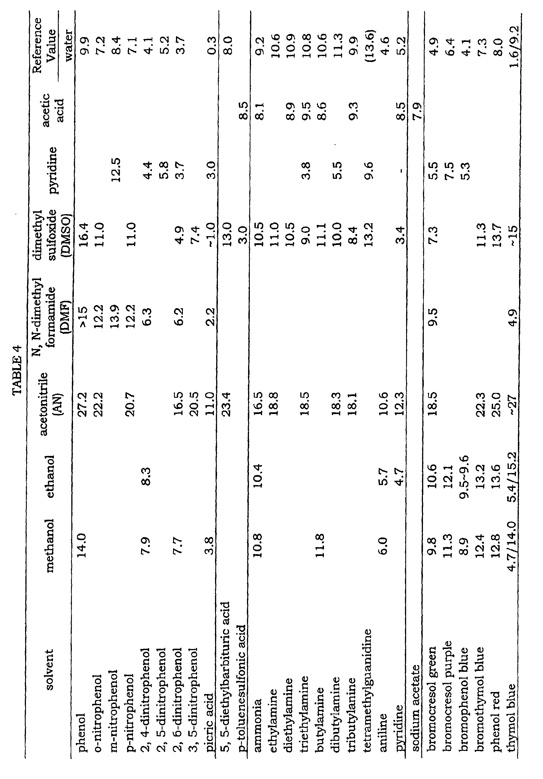
For example, the dissociation constant pKa of acidic
substance is a logarithm of the dissociation ratio Ka of the acidic
substance HA to hydrogen ion H+ and the anion A-.
Ka = (hydrogen ion H+ concentration) × (the anion A-
concentration) + (acidic substance concentration HA)
In this case, as described in Example 1, the substances
produced by the oxidation of the photoresist film are mainly acetic acid.
Therefore, as to the degree of ionization of the acidic substance produced
by oxidation decomposition of the photoresist, it is possible to refer to
the dissociation constant of acetic acid to acetic acid itself, which is
14.45 shown in Table 3.
Ka = (hydrogen ion H+ concentration) × (the anion A- concentration) +
(acidic substance concentration HA) = 10-14.45 .
When acetic acid is dissociated to hydrogen ion and an anion,
the respective ion concentrations are equal. Also, the acetic acid
concentration is about 6.3 mol/L.
hydrogen ion H+ concentration = 1.5 × 10⁻⁵ mol/L
pH = -log (H+ ) = 4.9
Therefore, even if acidic substance such as acetic acid was
produced by oxidation decomposition of the photoresist, pH is
theoretically decreased only to about pH = 5.
Then, the required amount of acetic acid will be described.
The amount of acetic acid vapor to be introduced to the treatment tank
is about 6.4 mg/minute when the temperature of the acetic acid solution
is 90°C. On the assumption that all acetic acid vapor introduced turns
into dew on the substrate, an acetic acid liquid film having a thickness of
0.064 mg/ (cm2·min) is to be formed per unit surface area of the
photoresist film. On the other hand, the conventional method shown in
Fig. 25 describes that a 50 µm-thick liquid film is formed on the
substrate to peel 1 µm-thick resist within 1 minute, which means 5
mg/ (cm2·min) of acetic acid is required per 1 cm2 unit surface area of the
resist and 1-minute treatment. In other words, in this Example, resist
was actually removed with acetic acid in an amount only about 1.3 % to
the amount required in a conventional technique.
As an index for the load on environment, comparison is made
as to the TOC emission amounts from the entire process including the
carbon amount contained in the introduced acetic acid and the carbon
amount in the photoresist film itself. The TOC amount per unit surface
area of the substrate generated when the photoresist film is completely
removed within two minutes is as follows:
(TOC production speed attributed to photoresist decomposition) =
(decrease rate of photoresist film) × (carbon ratio in the average molecule
of photoresist) = (0.0081 g + 2 min) × 0.8 + 100 cm2 = 0.032
mg/(cm2 ·min)
(TOC amount attributed to acetic acid introduced in this Example) =
(acetic acid introduction amount) × (carbon ratio in acetic acid molecule)
= 6.4 mg/min × 0.4 - 100 cm2 = 0.026 mg/(cm2 ·min)
(TOC amount attributed to acetic acid introduced in the conventional
example (Fig. 25)) = 5 mg/(cm2 ·min)
In an actual process for treating a substrate, it is necessary
to decompose the organic matter in waste liquid from apparatus. When
acetic acid in an amount of at least 150 times as much as the TOC
production speed of the photoresist itself is introduced, the
concentration of TOC contained in wastewater from apparatus reaches
0.032 mg × 150 + 1 = 4.8 mg/L, since the amount of wastewater from
apparatus is 1,000 cc/(min·cm2). This means that the value is
approximately the same level as that of the water quality standard
concerning living environment provided by the Environment Agency,
which is 5 mg/L to 10 mg/L. In a production plant, waste liquid from a
large number of apparatus is generally treated at one time, but it is also
desirable that the TOC amount in waste liquid from each piece of
apparatus is kept to at most the value in compliance with the
environmental standard. Accordingly, it is necessary to control the
amount of acetic acid to be introduced into the treatment process to at
most 150 times as high as the production speed of the substances
produced attributed to the decomposition of the photoresist.
In case of comparing this Example with the conventional
example (Fig. 25) in terms of the emission amount of TOC produced per
unit surface area of a substrate in the entire process, the value is:
Example / Conventional Example = [(0.032 + 0.026)
mg/(cm2 ·min)]/[(0.032 + 5.0)mg/(cm2 ·min)] = 1.1%.
It is made clear that this Example achieves complete removal
of the photoresist film with the load to environment of 1/100.
According to this Example, by keeping the substrate 2 to
temperature higher than room temperature and controlling the
temperature of the wet ozone-containing gas to be supplied to the
photoresist film on the substrate 2 to temperature equal to or higher
than that of the substrate 2, a proper acetic acid liquid film was formed
on the substrate and the photoresist film was removed. Further, this
Example proved that the Al film dissolution was actually prevented
because the acidic substance generated by oxidation decomposition of
the photoresist by ozone did not cause strong acidity in the acetic acid
liquid film having a purity of 99.7 %. It was also proved that treatment
of a substrate was achieved with an environmental load of about 1 % of
that of the conventional method.
In Example 6, acetic acid was used to prevent the ionization
of the substances on the substrate, which is generated by oxidation of
the photoresist film. But in this Example, experiments were carried out
using acetone as a solvent. Since the boiling point of acetone is 51°C,
the substrate was heated to 40°C. The gas sending tube 8a, the gas
sending tube 8b, the gas sending tube 8c and the header 5 were heated
to 50°C. After the respective temperature levels were stabilized,
acetone and ozone-containing gas (ozone concentration: 200 g/Nm3)
which had been passed through acetone heated to 50°C and humidified
by the humidifier 7 was supplied at a flow rate of 3,000 cc/minute. The
vapor pressure of acetone in gas containing acetone vapor and ozone
(hereinafter sometimes referred to as acetone- and ozone-containing gas)
was adjusted to the saturated vapor pressure at 50°C.
The results of Example 7 is that the pH on the substrate
surface after the photoresist removal was approximately neutral (pH = 5
to 6) in the range of residence time of 0.01 to 1.0 second and no change
was observed in the Al film thickness. When the time for the complete
removal by the wet ozone-containing gas at 90°C in Example 1 was set to
be 1, the time for the complete removal by the acetone- and ozone-containing
gas was shortened to be 0.7 to 0.8.
According to this Example, by keeping the substrate 2 to
temperature higher than room temperature and controlling the
temperature of the wet ozone-containing gas to be supplied to the
photoresist film on the substrate 2 to temperature equal to or higher
than that of the substrate 2, a proper acetone liquid film was formed on
the substrate and the photoresist film was removed. Further, this
Example proved that the Al film dissolution was actually prevented
because the acidic substance generated by oxidation decomposition of
the photoresist by ozone did not cause strong acidity in the acetone
liquid film.
In Examples 6 and 7, acetic acid and acetone were used in
order to prevent the ionization of the substances generated by oxidation
of the photoresist film on the substrate. However, the same effect was
observed in case of using methanol, ethanol, propanol, acetonitrile,
carbon tetrachloride, chloroform and the like. This is because the
acidic substance generated by the resist removal has low ionization
constant for the above-described solvents and thus the pH on the
substrate surface is not decreased even if the acidic substance is
dissolved.
In Examples 6 and 7, a solvent which prevents the ionization
of the substances generated by oxidation of photoresist film on the
substrate was used. However, when such a solvent has reactivity to
ozone, the resist removal property was deteriorated owing to the
consumption of ozone.
In this Example, chloroform or carbon tetrachloride was used
in place of acetic acid or acetone. In the treatment using ozone gas
containing chloroform or carbon tetrachloride, the time for complete
removal is shown in Table 5 (the time for complete removal of the resist
film by acetic acid- and ozone-containing gas in Example 6 was set to be
1).
According to "Theory and Practice of Ozone Use", p. 274,
published by Realize Co., the reaction speeds of ozone with carbon
tetrachloride and chloroform are described as 0.007 s-1M-1 and 2.1 s-1M-1,
respectively. In case of introducing chloroform, ozone is supposedly
consumed by reaction of ozone with chloroform. Similar tendency is
observed in case of using solvents such as methanol, ethanol and
propanol as well as in case of using chloroform.
In this way, a solvent having low reactivity with ozone is
preferable as a solvent to be introduced to prevent the ionization of
acidic substance produced by resist oxidation decomposition.
Examples 1 to 8 disclosed methods for treating a substrate in
case of using A1 as the wiring material of the substrate. Since A1 can
form a stable oxide in a pH range of 4 to 9 as described in the section of
the background art, the pH was adjusted to the range of 4 to 9 by
controlling flow rate of the additive gas and the like in Examples 1 to 5.
However, since different metals have different stable regions, it is
necessary to arrange such a condition as the amount of additive gas in
consideration of those stable regions.
Table 6 shows the pH ranges in which various metals can
form stable oxide when exposed to ozone-containing water.
| metal | pH range |
| aluminium | 4~9 |
| copper | 7~13 |
| nickel | at least 7 |
| tungsten | at most 4 |
| iron | at least 2 |
| zinc | 8~11 |
| indium | 5~11 |
| titanium | all |
| magnesium | at least 12 |
In this Example, films of various metals shown in Table 6
were formed and similarly investigated in place of Al metal in Example 1.
After treating a substrate by wet ozone-containing gas and
ammonia gas for one minute, the decomposed photoresist film was
removed by supplying pure water of 55°C to the substrate 2 at a flow rate
of 3,000 cc/minute. A series of the steps of 1-minute substrate
treatment and the rinsing with pure water was repeated until the
photoresist film on the substrate 2 was completely removed.
The flow rate of ammonia gas was changed and the film
thickness of various metals after the complete removal of the photoresist
by wet ozone-containing gas and ammonia gas was measured using a
stylus type film thickness profilometer. Further, after the treatment
with wet ozone-containing gas, the pH on the surface of the substrate
was measured just before the rinsing step with pure water.
In case of tungsten and titanium, no metal film corrosion was
observed even if the amount of ammonia supply was 0 since stable
oxides are formed even at pH 2.
Regarding other metals, the pH on the surface of the
substrate after the substrate treatment varied in accordance with the
change in the ammonia gas flow rate, and corrosion was prevented when
the pH entered the stable range of each metal. For example, in case of
magnesium, the ammonia flow rate necessary for the stabilization was
about 2,000 cc/minute, which was the highest, because magnesium is
stabilized in an alkaline state of at least pH 12. As described in
Example 1, since the production speed of the acidic substance molecule
produced by oxidation of the photoresist film is equal to the supply
speed of the ammonia molecule supplied at an ammonia gas flow rate of
60 cc/min, the supply speed of ammonia molecule at the above flow rate
of 2,000 cc/minute is about 33 times as high as the production speed of
the acidic substance molecule. To prevent metal dissolution completely
by introducing ammonia as described in Example 1, the flow rate of
ammonia gas was at least 2,000 cc/minute for magnesium, at most
1,750 cc/minute for indium, 1,000 cc/minute for tungsten, 1,750
cc/minute for zinc and 1,500 cc/minute for copper.
According to this Example, by keeping the substrate 2 to
temperature higher than room temperature and by adjusting the
temperature of the wet ozone gas supplied to the photoresist film on the
substrate 2 to at least the temperature of the substrate 2, a proper water
film was formed on the substrate and the photoresist film was removed.
Further, it was also proved that the dissolution of film of other metals
attributed to the acidic substance produced by oxidation decomposition
of the photoresist due to ozone could be prevented by controlling the pH
on the surface of the substrate 2 with adjusting the flow rate of ammonia
gas.
Differently from Embodiment 1 which mainly describes the
case of small size substrates, this Embodiment gives a detailed
explanation of a method of treating large size substrates such as a
substrate for LCD. Fig. 18 is a schematic view illustrating the
constitution of an apparatus for treating a substrate according to
Embodiment 2, which works effectively in case of treating a large size
substrate such as LCD substrate.
This apparatus for treating a substrate comprises a pre-heating
unit 51 for the substrate 2, an ozone treatment unit 52, a pure
water rinsing unit 53 and a drying unit 54. Rollers 55 continuously
transport the substrate 2 in one direction inside the apparatus and the
photoresist film previously formed on the substrate 2 is removed.
Ozone gas generated by an ozone generator 6 becomes wet gas by a
humidifier 7 and is introduced into the treatment units, together with an
additive gas produced in an additive gas generator 18.
A linear nozzle 56 having a length equal to the width of the
substrate 2 (in other words, the length in direction rectangular to the
transportation direction of the substrate) is installed in the ozone
treatment unit 52 and the wet ozone-containing gas and the additive gas
are sprayed to the substrate 2 through the nozzle 56 to remove the
photoresist on the substrate 2. Regarding the opening part of the
nozzle 56, a slit type nozzle or a nozzle with a large number of fine holes
can be employed.
The opening width of the slit type nozzle is preferably in a
range of 0.1 to 1 mm. On the other hand, in case of the nozzle with a
large number of holes, it is preferable to arrange a large number of holes
having a diameter of 0.1 to 1 mm at intervals of at most 10 mm.
When wet ozone-containing gas of high temperature arrives
at the nozzle 56 and temperature of the nozzle 56 is low, water turns into
dew inside the nozzle, there is fear of short supply of water to the
substrate 2 or dripping of condensed water on the substrate 2.
Therefore, the temperature of the nozzle 56 must be equal to or higher
than the ozone gas temperature. A heating means for preventing dew
formation are installed also in the humidifier for humidifying the
ozone-containing gas and a gas sending tube connecting the humidifier
and the nozzle 56 in the same manner as in Embodiment 1 though there
is no illustration in the figure.
The time from the mixing of wet ozone-containing gas with
the additive gas to the arrival of the gas mixture to the supply port of the
nozzle 56 can be adjusted by changing the distance from the mixing
point to the supply spot. By keeping the substrate 2 to temperature
higher than room temperature and by adjusting the temperature of the
wet ozone gas supplied to the photoresist film on the substrate 2 to at
least the temperature of the substrate 2, a proper water film was formed
on the substrate and the photoresist film was removed. Further, by
controlling the supply amount of the additive gas and the mixing
duration of the additive gas with the wet ozone-containing gas, the pH on
the surface of the substrate 2 was increased, and thus it was possible to
prevent dissolution of the wiring metal attributed to the acidic substance
produced by oxidation decomposition of the photoresist by ozone.
Embodiment 3 of the invention is carried out by using the
apparatus for treating a substrate described in Embodiment 2, with
providing a plurality of nozzles for the apparatus to supply the wet
ozone-containing gas and the additive gas to substrate 2 separately.
Fig. 19 shows an enlarged view of the ozone treatment unit
52 (Fig. 18) shown in Fig. 18. The ozone gas generated by the ozone
generator 6 becomes wet gas by the humidifier 7 and introduced into the
treatment units, together with an additive gas produced in an additive
gas generator 18. Fig. 19 shows the case of using three nozzles 61 for
the wet ozone-containing gas and three nozzles 62 for the additive gas.
The additive gas is introduced for the purpose of neutralizing the acidic
substance produced at the time of decomposition of the photoresist
molecules by the wet ozone gas. Therefore, more effective results can
be obtained when the distance d 1 between the wet ozone-containing gas
nozzle and the additive gas nozzle is shorter. The distance d is
preferably in a range of 10 to 300 mm. On the other hand, it is more
effective to define the distances d2 evenly among the ozone nozzles in the
ozone treatment units.
By supplying the wet ozone-containing gas and the additive
gas separately through different nozzles, the interaction between the wet
ozone-containing gas and the additive gas can beminimized, which
occurs before arriving at the surface of the substrate. By adjusting the
nozzle distances d1 and d2 properly, dissolution of the wiring metal on
the substrate can be prevented with maintaining photoresist removal
capability high. Further, though the case of using respective three
nozzles was shown in Fig. 19, the number of each nozzle should be
determined depending on the size of the substrate and the size of the
ozone treatment units.
Embodiment 4 of the invention is carried out by using the
apparatus for treating a substrate described in Embodiment 2, and an
impurity removal tower 58 is further installed in the rear stage of the
ozone generator 6 to supply wet ozone-containing gas to the substrate as
illustrated in Fig. 20.
This apparatus for treating a substrate comprises a preheating
unit 51 for a substrate 2, an ozone treatment unit 52, a pure
water rinsing unit 53 and a drying unit 54. Rollers 55 continuously
transport the substrate 2 in one direction inside the apparatus and the
photoresist film previously formed on the substrate 2 is removed.
Ozone gas generated by the ozone generator 6 becomes wet gas by a
humidifier 7 and is introduced into the treatment units, together with an
additive gas produced in an additive gas generator 18.
In case of treating a large size LCD substrate, the amount of
the photoresist film, which is an object to be treated is increased, and
therefore the amount of ozone gas introduced to the ozone treatment
unit is also increased. As a typical example of a large volume ozone
generator, there is an electric discharge type ozone generation method.
As to the method, it is known that generation efficiency is improved
when a small amount of nitrogen is added to oxygen which is a raw
material gas. In case of the electric discharge type ozone generation
method using nitrogen gas, nitrogen oxide is produced along with ozone
generation, indicating a possibility of corrosion at the constituent
material of the photoresist film treatment apparatus and the wiring
metal on the substrate. Since nitrogen dioxide has high solubility in
water and is easily ionized to generate nitrate ion, it is likely that strong
acidity is caused.
In addition, there are some of electric discharge type ozone
generators which generate metal ions and fine particles due to
sputtering phenomenon in electrodes. The intake of impurity metals to
the LCD substrate sometimes causes serious effects on products.
The constitution of the impurity removal tower is shown in
Fig. 21. Pure water is supplied to a treatment tower 71 at a constant
flow rate through a pure water pump 73 and excess pure water is
discharged out of an overflow port 74. The ozone-containing gas
generated by the ozone generator 6 is supplied to the treatment tower 71
and sufficiently brought into contact with pure water by a stirrer 72, so
that impurities such as nitrogen oxide and metal ions are dissolved in
the pure water and removed almost perfectly.
A tube from the overflow port 74 to a water discharge channel
is once extended downward and then turned back upward as shown in
the figure. According to this, the tube is provided with a structure in
which water pole is always kept to be at a constant height (L (mm)) in the
tube. When the flow pressure of the ozone gas is p [mmH2O], L [mm] is
preferably at least 2p [mm].
Embodiment 5 of the invention is carried out by employing a
voltage adjuster in place of the additive gas generator as described in
Embodiment 1. As illustrated in Fig. 22, the potential of the metal
wiring is kept constant by leading out a conducting wire from the wiring
metal on the substrate 2 and connecting the conducting wire to the
voltage adjuster 81 to prevent corrosion of the metal wiring.
Another reason for the corrosion of metal in ozone-containing
water in addition to the pH discussed in detail above include high
oxidation potential (at least 1.5 V) of ozone-containing water. Generally,
when metal is exposed to ozone-containing water, the potential of the
metal surface is increased to the high oxidation potential of ozone-containing
water to promote corrosion. On the other hand, according
to ATLAS OF ELECTROCHEMICAL EQUILIBRIA IN AQUEOUS
SOLUTIONS (Pergamon Press 1966), almost all metals do not produce
oxide film and can be stabilized in a state of pure metal when the redox
potential is at most -2.0 V.
Example 10 was carried out with changing the voltage of the
voltage adjuster 81 in Embodiment 5. A series of steps of 1-minute
substrate treatment and the rinsing with pure water was repeated in the
same manner as Example 1 until the photoresist film on the substrate 2
was completely removed.
An aluminum film, a chromium film and a molybdenum film
were separately formed on substrates whose surfaces were cleaned in a
thickness of 200 nm. Thereafter, a 1,450 nm-thick photoresist film
which was an object to be treated was formed on each substrate. The
set value of the voltage adjuster was changed in a range of +3 to -3 V and
the Al film thickness after complete removal of the photoresist by wet
ozone-containing gas was measured by using a stylus type film
thickness profilometer.
The film thickness measured values of the respective metals
are shown in Fig. 11 as the results obtained in Example 10. Since
treatment was carried out only with the wet ozone-containing gas in this
Example, the pH on each substrate measured just before the rising step
after the ozone treatment was about pH 2. When the voltage set value
was positive, preventing effect on metal corrosion was not observed.
When the voltage set value was negative, it is found that corrosion was
prevented in a range near the redox potential of the respective metals.
According to this Example, by keeping the temperature of the
substrate 2 to higher than room temperature and by adjusting the
temperature of the wet ozone gas supplied to the photoresist film on the
substrate 2 to at least the temperature of the substrate 2, a proper water
film was formed on the substrate and the photoresist film was removed.
Further, it was also proved that the metal film dissolution attributed to
the acidic substance produced by oxidation decomposition of the
photoresist due to ozone could be prevented by controlling the potential
of wiring on the substrate.
In Reference Example 1, investigation was made as in
Example 1 with changing the pH on the substrate surface on purpose by
using additive gas but without forming photoresist film on the substrate
previously.
A surface-cleaned substrate 2 (a 0.7 mm-thick glass
substrate on which a 200 nm-thick Al film was already formed) was cut
into a size of 100 mm × 100 mm. The substrate was placed on the plate
heater in the treatment chamber 1 with the Al film upward and heated to
73°C. The gas sending tube 8a, the gas sending tube 8b, the gas
sending tube 8c and the header 5 were heated to 90°C. After the
respective temperature levels were stabilized, wet ozone-containing gas
(ozone concentration: 200 g/Nm3) passed through pure water heated to
90°C and humidified by the humidifier 7 was supplied at a flow rate of
5,000 cc/minute. The humidity of the wet ozone-containing gas
wasadjusted to the saturated vapor concentration at 90°C. Nitrogen
dioxide gas was used as acidic substance added to adjust the pH on the
substrate and the gas flow rate was adjusted by a mass flow controller.
Nitrogen dioxide gas and wet ozone-containing gas were mixed at a point
d = 100 mm before the supply port of a header 5 and supplied to the
surface of the substrate 2.
After treating the substrate by wet ozone-containing gas and
nitrogen dioxide gas for 1 minute, pure water of 55°C was supplied to the
substrate 2 at a flow rate of 3,000 cc/minute to clean the same.
The flow rate of nitrogen dioxide was changed in a range of 0
to 200 cc/minute and the Al film thickness after substrate treatment
with wet ozone-containing gas and nitrogen dioxide gas was measured
by a stylus type film thickness profilometer.
The results of Reference Example 1 are shown in Fig. 26.
When the flow rate of nitrogen dioxide is at least 40 cc/minute, the pH
on the substrate was decreased to at most pH 4 and decrease of film
thickness owing to the Al film corrosion was observed. On the other
hand, when the flow rate of nitrogen dioxide gas was 0 cc/minute, the
pH on the substrate was about pH 7 and no change was observed in Al
film thickness.
Corrosion of Al film was not observed when nitrogen dioxide
gas was not used. This means that the Al film corrosion observed in
Examples 1 to 3 was not caused by the wet ozone-containing gas itself.
In other words, it was proved that the cause of the complete dissolution
of the Al film at an ammonia gas flow rate of 0 cc/minute as shown in the
results of Example 1 (Fig. 2) was the pH decrease on the substrate
attributed to the acidic substance produced by the reaction of the wet
ozone-containing gas and the photoresist.
In Reference Example 2, investigation was made as in
Example 1 with adjusting the pH on the substrate surface to pH 2 by
using additive gas but without forming photoresist film on the substrate
previously. Further, experiments were also made as to the cases where
the temperature of the substrate was changed in a range of 50 to 85°C.
As shown in Fig. 1, a surface-cleaned substrate 2 (a 0.7
mm-thick glass substrate on which a 200 nm-thick Al film was already
formed) was cut into a size of 100 mm × 100 mm. The substrate was
placed on the plate heater 4 in the treatment chamber 1 with the Al film
upward and heated to a prescribed temperature. The gas sending tube
8a, the gas sending tube 8b, the gas sending tube 8c and the header 5
were heated to 90°C. After the respective temperature levels were
stabilized, wet ozone-containing gas (ozone concentration: 200 g/Nm3)
passed through pure water heated to 90°C and humidified by the
humidifier 7 was supplied at a flow rate of 5,000 cc/minute. The
humidity of the wet ozone-containing gas was adjusted to the saturated
vapor concentration at 90°C. Nitrogen dioxide gas was used as acidic
gas added to adjust the pH on the substrate and the gas flow rate was
adjusted by a mass flow controller 21. The nitrogen dioxide gas and the
wet ozone-containing gas were mixed at a point d = 100 mm before the
supply port of the header 5 and supplied to the surface of the substrate
2.
After treating the substrate by wet ozone-containing gas and
nitrogen dioxide gas for 1 minute, pure water of 55°C was supplied to the
substrate 2 at a flow rate of 3,000 cc/minute to clean the same.
The set temperature of the substrate was changed to 50°C,
70°C and 85°C and the Al film thickness after substrate treatment with
wet ozone-containing gas and nitrogen dioxide gas was measured by a
stylus type film thickness profilometer. Generally, the amount of water
which condenses on the substrate is increased as the difference of the
substrate temperature and the wet gas temperature becomes wide.
Therefore, the flow rate of the nitrogen dioxide gas was increased by
using a mass flow controller so as to adjust the pH on the substrate
surface to be pH 2 before the rinsing with pure water after 1-minute
substrate treatment.
The results of Reference Example 2 are shown in Table 7.
The table shows the correlation between the temperature of the
substrate to be treated and the aluminum film thickness after the
treatment (at pH = 2). It is found that the film is dissolved by more than
half of the initial film thickness, i.e., 200 nm for 1-minute treatment at
70°C. When the substrate temperature was 50°C, the Al film showed
little decrease in film thickness even after 1-minute treatment using wet
ozone-containing gas and nitrogen dioxide gas. Thus, it was proved
that the lowering of the substrate temperature was effective in
preventing the Al film corrosion.
However, in case of oxidation decomposition of the
photoresist film by using wet ozone-containing gas as in Examples 1 to 3,
the oxidation decomposition speed is probably decreased with the
decrease of the substrate temperature.
| substrate temperature (°C) | Al film thickness (nm) |
| 50 | 160 |
| 70 | 80 |
| 85 | 12.5 |
The first process for treating a substrate of the invention is a
process for treating a substrate which comprises removing organic
pollutant on the surface of the substrate using mixed gas of wet-ozone
containing gas wetted by steam and basic gas, wherein a supply speed of
basic gas molecule is controlled to at most 100 times as high as the
production speed of molecule of acidic substance produced by oxidation
reaction of the organic pollutant. According to this, it becomes possible
to maintain the pH value on the substrate to be treated in such a range
that wiring metal previously formed on the substrate is present in a
stable state and therefore prevention of the corrosion of the wiring metal
is achieved.
The second process for treating a substrate of the present
invention is a process in which a volatile substance is introduced as the
basic gas. According to this, it becomes possible to maintain the pH
value on the substrate to be treated in such a range that wiring metal
previously formed on the substrate is present in a stable state and
therefore prevention of the corrosion of the wiring metal is achieved.
The third process for treating a substrate of the present
invention is a process in which ammonia gas is used as thebasic gas.
According to this, it becomes possible to maintain the pH value on the
substrate to be treated in such a range that wiring metal previously
formed on the substrate is present in a stable state and therefore
prevention of the corrosion of the wiring metal is achieved.
The fourth process for treating a substrate of the present
invention is a process in which ammonia gas passed through saturated
ammonia is used as the basic gas. According to this, it becomes
possible to maintain the pH value on the substrate to be treated in such
a range that wiring metal previously formed on the substrate is present
in a stable state and therefore prevention of the corrosion of the wiring
metal is achieved.
The fifth process for treating a substrate of the present
invention is a process in which a non-volatile substance is used as the
basic gas. According to this, it becomes possible to maintain the pH
value on the substrate to be treated in such a range that wiring metal
previously formed on the substrate is present in a stable state and
therefore prevention of the corrosion of the wiring metal is achieved.
The sixth process for treating a substrate of the present
invention is a process in which TMAH (tetramethylammonium
hydroxide) is used as the non-volatile substance. According to this, it
becomes possible to maintain the pH value on the substrate to be
treated in such a range that wiring metal previously formed on the
substrate is present in a stable state and therefore prevention of the
corrosion of the wiring metal is achieved.
The seventh process for treating a substrate of the present
invention is a process in which the mixing duration from the mixing of
the basic gas molecule and the wet ozone-containing gas to the arrival of
the gas mixture at the substrate to be treated is controlled to at most 10
seconds. According to this, it becomes possible to maintain the pH
value on the substrate to be treated in such a range that wiring metal
previously formed on the substrate is present in a stable state and
therefore prevention of the corrosion of the wiring metal is achieved.
The eighth process for treating a substrate of the present
invention is a process for treating a substrate which comprises removing
organic pollutant on the surface of the substrate using wet ozone-containing
gas wetted by a treatment liquid, wherein a solvent capable of
preventing ionization of acidic substance produced by the oxidation
reaction of the organic pollutant is used as the treatment liquid.
According to this, it becomes possible to maintain the pH value on the
substrate to be treated in such a range that wiring metal previously
formed on the substrate is present in a stable state and therefore
prevention of the corrosion of the wiring metal is achieved.
The ninth process for treating a substrate of the present
invention is a process in which a solvent having low reactivity to ozone is
used as the treatment liquid. According to this, it becomes possible to
maintain the pH value on the substrate to be treated in such a range
that wiring metal previously formed on the substrate is present in a
stable state and therefore prevention of the corrosion of the wiring metal
is achieved.
The tenth process for treating a substrate of the present
invention is a process in which acetic acid or acetone is used as
thetreatment liquid. According to this, it becomes possible to maintain
the pH value on the substrate to be treated in such a range that wiring
metal previously formed on the substrate is present in a stable state and
therefore prevention of the corrosion of the wiring metal is achieved.
The eleventh process for treating a substrate of the present
invention is a process in which the supply speed of molecule of the
solvent is controlled to at most 150 times as high as the production
speed of molecule of the acidic substance produced by the oxidation
reaction of the organic pollutant. According to this, it becomes possible
to maintain the pH value on the substrate to be treated in such a range
that wiring metal previously formed on the substrate is present in a
stable state and therefore prevention of the corrosion of the wiring metal
is achieved.
The twelfth process for treating a substrate of the present
invention is a process in which voltage of wired metal previously formed
on the substrate is adjusted. According to this, it becomes possible to
maintain the potential on the substrate to be treated within a redox
potential range that wiring metal previously formed on the substrate is
present in a stable state and therefore prevention of the corrosion of the
wiring metal is achieved.
The first apparatus for treating a substrate of the present
invention comprises a substrate heating means for keeping a substrate
at temperature higher than room temperature, a wetting means for
obtaining wet ozone-containing gas by wetting, with a treatment liquid,
ozone-containing gas generated by an ozone generator, a supplying
means for supplying the wet ozone-containing gas to substance to be
treated on the surface of the substrate, a gas sending tube for
connecting the wetting means and the supplying means, a gas heating
means for heating each of the wetting means, the supplying means and
the gas sending tube to temperature equal to or higher than that of the
substrate, and a supplying means for supplying a basic gas-containing
gas to the substance to be treated on the surface of the substrate.
According to this, it becomes possible to maintain the pH on the
substrate to be treated in such a range that wiring metal previously
formed on the substrate is present in a stable state and therefore
prevention of the corrosion of the wiring metal is achieved.
The second apparatus for treating a substrate of the present
invention further comprises a removing means for removing undesirable
impurities generated from the ozone generator between the ozone
generator and the wetting means for wetting the ozone-containing gas.
According to this, it becomes possible to maintain the pH on the
substrate to be treated in such a range that wiring metal previously
formed on the substrate is present in a stable state and therefore
prevention of the corrosion of the wiring metal is achieved.
The third apparatus for treating a substrate of the present
invention comprises a substrate heating means for keeping a substrate
at temperature higher than room temperature, a wetting means for
obtaining wet ozone-containing gas by wetting, with a treatment liquid,
ozone-containing gas generated by an ozone generator, a supplying
means for supplying the wet ozone-containing gas to substance to be
treated on the surface of the substrate, a gas sending tube for
connecting the wetting means and the supplying means, a gas heating
means for heating each of the wetting means, the supplying means and
the gas sending tube to temperature equal to or higher than that of the
substrate, and a controlling means capable of adjusting the potential of
a metal wiring previously formed on the substrate. According to this, it
becomes possible to maintain the potential on the substrate to be
treated within a redox potential range that wiring metal previously
formed on the substrate is present in a stable state and therefore
prevention of the corrosion of the wiring metal is achieved.
Claims (15)
- A process for treating a substrate by removing organic pollutant on the surface of the substrate using mixed gas of basic gas and wet ozone-containing gas wetted by steam, wherein a supply speed of basic gas molecule is at most 100 times as high as the production speed of molecule of acidic substance produced by oxidation reaction of the organic pollutant.
- The process for treating a substrate of Claim 1, wherein a volatile substance is introduced as the basic gas.
- The process for treating a substrate of Claim 2, wherein the volatile substance is ammonia gas.
- The process for treating a substrate of Claim 3, wherein the ammonia gas is passed through a saturated aqueous solution of ammonia.
- The process for treating a substrate of Claim 1, wherein a non-volatile substance is introduced as the basic gas.
- The process for treating a substrate of Claim 5, wherein the non-volatile substance is tetramethylammonium hydroxide.
- The process for treating a substrate of Claim 1, wherein the mixing duration from the mixing of the basic gas molecule and the wet ozone-containing gas to the arrival of the gas mixture at the substrate to be treated is at most 10 seconds.
- A process for treating a substrate by removing organic pollutant on the surface of the substrate using wet ozone-containing gas wetted by treatment liquid, which comprises using, as the treatment liquid, a solvent capable of preventing ionization of acidic substance produced by oxidation reaction of the organic pollutant.
- The process for treating a substrate of Claim 8, wherein the treatment liquid is a solvent having low reactivity to ozone.
- The process for treating a substrate of Claim 9, wherein the solvent having low reactivity to ozone is acetic acid or acetone.
- The process for treating a substrate of Claim 8, wherein the supply speed of molecule of the solvent is at most 150 times as high as the production speed of molecule of the acidic substance produced by oxidation reaction of the organic pollutant.
- A process for treating a substrate by removing organic pollutant on the surface of the substrate using wet ozone-containing gas wetted by treatment liquid, which comprises adjusting voltage of wired metal previously formed on the substrate.
- An apparatus for treating a substrate comprising a substrate heating means for keeping a substrate at temperature higher than room temperature, a wetting means for obtaining wet ozone-containing gas by wetting, with a treatment liquid, ozone-containing gas generated by an ozone generator, a supplying means for supplying the wet ozone-containing gas to substance to be treated on the surface of the substrate, a gas sending tube for connecting the wetting means and the supplying means, a gas heating means for heating each of the wetting means, the supplying means and the gas sending tube to temperature equal to or higher than that of the substrate, and a supplying means for supplying basic gas-containing gas to the substance to be treated on the surface of the substrate.
- The apparatus for treating a substrate of Claim 13, further comprising a removing means for removing undesirable impurities generated from the ozone generator between the ozone generator and the wetting means for wetting the ozone-containing gas.
- An apparatus for treating a substrate comprising a substrate heating means for keeping a substrate at temperature higher than room temperature, a wetting means for obtaining wet ozone-containing gas by wetting, with a treatment liquid, ozone-containing gas generated by an ozone generator, a supplying means for supplying the wet ozone-containing gas to substance to be treated on the surface of the substrate, a gas sending tube for connecting the wetting means and the supplying means, a gas heating means for heating each of the wetting means, the supplying means and the gas sending tube to temperature equal to or higher than that of the substrate, and a controlling means capable of adjusting the potential of a metal wiring previously formed on the substrate.
Applications Claiming Priority (3)
| Application Number | Priority Date | Filing Date | Title |
|---|---|---|---|
| WOPCT/JP00/06694 | 2000-09-28 | ||
| PCT/JP2000/006694 WO2002027775A1 (en) | 2000-09-28 | 2000-09-28 | Method and apparatus for treating wafer |
| PCT/JP2001/004962 WO2002027776A1 (en) | 2000-09-28 | 2001-06-12 | Substrate processing method, and apparatus therefor |
Publications (2)
| Publication Number | Publication Date |
|---|---|
| EP1255287A1 true EP1255287A1 (en) | 2002-11-06 |
| EP1255287A4 EP1255287A4 (en) | 2008-07-09 |
Family
ID=11736531
Family Applications (1)
| Application Number | Title | Priority Date | Filing Date |
|---|---|---|---|
| EP01936972A Withdrawn EP1255287A4 (en) | 2000-09-28 | 2001-06-12 | METHOD AND APPARATUS FOR TREATING SUBSTRATE |
Country Status (6)
| Country | Link |
|---|---|
| US (1) | US20030066549A1 (en) |
| EP (1) | EP1255287A4 (en) |
| JP (1) | JPWO2002027776A1 (en) |
| KR (1) | KR100458784B1 (en) |
| TW (2) | TW501178B (en) |
| WO (2) | WO2002027775A1 (en) |
Cited By (1)
| Publication number | Priority date | Publication date | Assignee | Title |
|---|---|---|---|---|
| WO2006034030A1 (en) * | 2004-09-17 | 2006-03-30 | Fsi International, Inc. | Using ozone to process wafer like objects |
Families Citing this family (19)
| Publication number | Priority date | Publication date | Assignee | Title |
|---|---|---|---|---|
| US20040159335A1 (en) * | 2002-05-17 | 2004-08-19 | P.C.T. Systems, Inc. | Method and apparatus for removing organic layers |
| KR100487549B1 (en) * | 2002-09-26 | 2005-05-03 | 삼성전자주식회사 | Air supply apparatus for semiconductor device fabrication equipment |
| DE10254990A1 (en) * | 2002-11-26 | 2004-07-22 | Technotrans Ag | Process for removing organic residues from finely structured surfaces |
| KR100906634B1 (en) * | 2003-01-20 | 2009-07-10 | 삼성전자주식회사 | Pattern Forming Method and Fabrication Method of Thin Film Transistor Substrate of Liquid Crystal Display |
| US7235479B2 (en) * | 2004-08-26 | 2007-06-26 | Applied Materials, Inc. | Organic solvents having ozone dissolved therein for semiconductor processing utilizing sacrificial materials |
| KR100666380B1 (en) * | 2005-05-30 | 2007-01-09 | 삼성전자주식회사 | A photoresist removal method and a method of manufacturing a semiconductor device using the same. |
| EP1968075B1 (en) * | 2005-11-29 | 2011-08-31 | Areva NP GmbH | Method for decontaminating an oxidised surface of a component or a system of a nuclear plant |
| JP4786351B2 (en) * | 2006-01-20 | 2011-10-05 | 株式会社東芝 | Processing apparatus and processing method |
| DE102008048540A1 (en) * | 2008-09-15 | 2010-04-15 | Gebr. Schmid Gmbh & Co. | Process for the treatment of substrates, substrate and treatment device for carrying out the method |
| US8603924B2 (en) * | 2010-10-19 | 2013-12-10 | Taiwan Semiconductor Manufacturing Company, Ltd. | Methods of forming gate dielectric material |
| CN102610562A (en) * | 2012-03-23 | 2012-07-25 | 上海华力微电子有限公司 | Method for removing carbon element in carbon-contained thin film and regenerating method of SiOC control baffle plate |
| JP6300139B2 (en) * | 2012-05-15 | 2018-03-28 | 株式会社Screenホールディングス | Substrate processing method and substrate processing system |
| US10524524B2 (en) * | 2013-06-28 | 2020-01-07 | F. Harlan Batrus | Methods and devices for protective filtration and delivery of respirable compounds |
| CN103646915A (en) * | 2013-11-28 | 2014-03-19 | 上海华力微电子有限公司 | A method for removing a C element in a SiCN thin film and a cyclic regeneration processing technique of a monitoring sheet containing the SiCN thin film |
| JP6520490B2 (en) * | 2015-07-08 | 2019-05-29 | 信越化学工業株式会社 | Pattern formation method |
| JP6779701B2 (en) * | 2016-08-05 | 2020-11-04 | 東京エレクトロン株式会社 | A storage medium in which a substrate processing apparatus, a substrate processing method, and a program for executing the substrate processing method are recorded. |
| JP6811675B2 (en) * | 2017-04-28 | 2021-01-13 | 株式会社Screenホールディングス | Substrate processing method and substrate processing equipment |
| JP6995547B2 (en) * | 2017-09-22 | 2022-01-14 | 株式会社Screenホールディングス | Chemical solution generation method, chemical solution generator and substrate processing device |
| US12420313B2 (en) * | 2022-08-09 | 2025-09-23 | Taiwan Semiconductor Manufacturing Company, Ltd. | Onsite cleaning system and method |
Family Cites Families (16)
| Publication number | Priority date | Publication date | Assignee | Title |
|---|---|---|---|---|
| JPH0724265B2 (en) * | 1988-04-13 | 1995-03-15 | 日本電気株式会社 | Semiconductor substrate cleaning equipment |
| JPH05109686A (en) * | 1991-10-14 | 1993-04-30 | Nippon Steel Corp | Method and apparatus for cleaning silicon wafer |
| JPH05206021A (en) * | 1992-01-28 | 1993-08-13 | Hitachi Ltd | Method and apparatus for manufacture of semiconductor device |
| JPH0741326B2 (en) * | 1992-04-10 | 1995-05-10 | 株式会社コスメック | Mold fall prevention device |
| JPH0684843A (en) * | 1992-09-02 | 1994-03-25 | Matsushita Electric Ind Co Ltd | Surface treatment equipment |
| KR940012061A (en) * | 1992-11-27 | 1994-06-22 | 가나이 쯔또무 | Organic matter removal method and organic matter removal apparatus for using the method |
| US5589422A (en) * | 1993-01-15 | 1996-12-31 | Intel Corporation | Controlled, gas phase process for removal of trace metal contamination and for removal of a semiconductor layer |
| JPH0974080A (en) * | 1995-09-04 | 1997-03-18 | Mitsubishi Gas Chem Co Inc | Method for cleaning semiconductor substrate with ozone |
| US20020157686A1 (en) * | 1997-05-09 | 2002-10-31 | Semitool, Inc. | Process and apparatus for treating a workpiece such as a semiconductor wafer |
| US6701941B1 (en) * | 1997-05-09 | 2004-03-09 | Semitool, Inc. | Method for treating the surface of a workpiece |
| US6869487B1 (en) * | 1997-05-09 | 2005-03-22 | Semitool, Inc. | Process and apparatus for treating a workpiece such as a semiconductor wafer |
| JP2003533865A (en) * | 1998-07-29 | 2003-11-11 | シーエフエムテイ・インコーポレーテツド | Method of wet processing an electronic component using an ozone-containing process fluid in the manufacture of the electronic component |
| JP3680577B2 (en) * | 1998-09-17 | 2005-08-10 | セイコーエプソン株式会社 | Resist removal cleaning method and apparatus |
| JP3869566B2 (en) * | 1998-11-13 | 2007-01-17 | 三菱電機株式会社 | Photoresist film removal method and apparatus |
| JP3671389B2 (en) * | 1999-12-03 | 2005-07-13 | 三菱電機株式会社 | Substrate processing method and apparatus |
| CN1460037A (en) * | 2000-03-13 | 2003-12-03 | 马特森技术公司 | Processes and apparatus for treating electronic components |
-
2000
- 2000-09-28 WO PCT/JP2000/006694 patent/WO2002027775A1/en not_active Ceased
- 2000-09-29 TW TW089120169A patent/TW501178B/en active
-
2001
- 2001-06-12 WO PCT/JP2001/004962 patent/WO2002027776A1/en not_active Ceased
- 2001-06-12 KR KR10-2002-7006775A patent/KR100458784B1/en not_active Expired - Fee Related
- 2001-06-12 JP JP2002531474A patent/JPWO2002027776A1/en active Pending
- 2001-06-12 EP EP01936972A patent/EP1255287A4/en not_active Withdrawn
- 2001-06-12 US US10/111,913 patent/US20030066549A1/en not_active Abandoned
- 2001-07-25 TW TW090118120A patent/TW512456B/en not_active IP Right Cessation
Cited By (1)
| Publication number | Priority date | Publication date | Assignee | Title |
|---|---|---|---|---|
| WO2006034030A1 (en) * | 2004-09-17 | 2006-03-30 | Fsi International, Inc. | Using ozone to process wafer like objects |
Also Published As
| Publication number | Publication date |
|---|---|
| US20030066549A1 (en) | 2003-04-10 |
| KR20020081213A (en) | 2002-10-26 |
| TW501178B (en) | 2002-09-01 |
| KR100458784B1 (en) | 2004-12-03 |
| JPWO2002027776A1 (en) | 2004-02-05 |
| EP1255287A4 (en) | 2008-07-09 |
| WO2002027775A1 (en) | 2002-04-04 |
| TW512456B (en) | 2002-12-01 |
| WO2002027776A1 (en) | 2002-04-04 |
Similar Documents
| Publication | Publication Date | Title |
|---|---|---|
| EP1255287A1 (en) | Substrate processing method, and apparatus therefor | |
| CN100413606C (en) | Method for producing cleaning solution and cleaning method thereof | |
| US5378317A (en) | Method for removing organic film | |
| KR100514598B1 (en) | Method and apparatus for recovering photoresist film | |
| CN102498550B (en) | Method for etching silicon-containing film | |
| US6742944B2 (en) | Alkaline solution and manufacturing method, and alkaline solution applied to pattern forming method, resist film removing method, solution application method, substrate treatment method, solution supply method, and semiconductor device manufacturing method | |
| KR101004159B1 (en) | Silicon etching method | |
| JP2001223206A (en) | Substrate processing method and apparatus | |
| JP2002270575A (en) | Etching method, semiconductor device and etching apparatus manufactured by this method | |
| CN101312794A (en) | Method for removing material from a substrate | |
| US20210043440A1 (en) | Method of producing heated ozone water, heated ozone water, and semiconductor wafer-cleaning liquid | |
| CN102459092A (en) | Hydroxyl radical-containing water supply method and hydroxyl radical-containing water supply device | |
| EP2733724B1 (en) | Method for cleaning metal gate semiconductor | |
| US20060084260A1 (en) | Copper processing using an ozone-solvent solution | |
| WO2012073574A1 (en) | Method for removal of photoresist | |
| JP2002231696A (en) | Resist removal method and apparatus | |
| US20070181165A1 (en) | Stripping and removal of organic-containing materials from electronic device substrate surfaces | |
| WO2010035522A1 (en) | Method and apparatus for etching silicon-containing film | |
| TW404853B (en) | Wet processing methods for the manufacture of electronic components using ozonated process fluids | |
| TWI343845B (en) | Stripping and cleaning of organic-containing materials from electronic device substrate surfaces | |
| JP2005136439A (en) | Substrate processing method | |
| JP5143230B2 (en) | Stripping and removing organic-containing materials from the surface of electronic device substrates | |
| JPH04111308A (en) | Method for removing organic material film | |
| JP2003197593A (en) | Substrate processing method and apparatus | |
| JPH0645308A (en) | Method of replenishing liquid mixture |
Legal Events
| Date | Code | Title | Description |
|---|---|---|---|
| PUAI | Public reference made under article 153(3) epc to a published international application that has entered the european phase |
Free format text: ORIGINAL CODE: 0009012 |
|
| 17P | Request for examination filed |
Effective date: 20020619 |
|
| AK | Designated contracting states |
Kind code of ref document: A1 Designated state(s): DE FR GB |
|
| RAP1 | Party data changed (applicant data changed or rights of an application transferred) |
Owner name: SPC ELECTRONICS CORPORATION Owner name: MITSUBISHI DENKI KABUSHIKI KAISHA |
|
| A4 | Supplementary search report drawn up and despatched |
Effective date: 20080605 |
|
| STAA | Information on the status of an ep patent application or granted ep patent |
Free format text: STATUS: THE APPLICATION HAS BEEN WITHDRAWN |
|
| 18W | Application withdrawn |
Effective date: 20080827 |