EP1255165A2 - Coating system and system for producing photoconductive elements for electrophotography - Google Patents
Coating system and system for producing photoconductive elements for electrophotography Download PDFInfo
- Publication number
- EP1255165A2 EP1255165A2 EP02009305A EP02009305A EP1255165A2 EP 1255165 A2 EP1255165 A2 EP 1255165A2 EP 02009305 A EP02009305 A EP 02009305A EP 02009305 A EP02009305 A EP 02009305A EP 1255165 A2 EP1255165 A2 EP 1255165A2
- Authority
- EP
- European Patent Office
- Prior art keywords
- coating
- works
- cores
- coated
- processing device
- Prior art date
- Legal status (The legal status is an assumption and is not a legal conclusion. Google has not performed a legal analysis and makes no representation as to the accuracy of the status listed.)
- Granted
Links
Images

Classifications
-
- G—PHYSICS
- G03—PHOTOGRAPHY; CINEMATOGRAPHY; ANALOGOUS TECHNIQUES USING WAVES OTHER THAN OPTICAL WAVES; ELECTROGRAPHY; HOLOGRAPHY
- G03G—ELECTROGRAPHY; ELECTROPHOTOGRAPHY; MAGNETOGRAPHY
- G03G5/00—Recording-members for original recording by exposure, e.g. to light, to heat or to electrons; Manufacture thereof; Selection of materials therefor
- G03G5/02—Charge-receiving layers
- G03G5/04—Photoconductive layers; Charge-generation layers or charge-transporting layers; Additives therefor; Binders therefor
- G03G5/05—Organic bonding materials; Methods for coating a substrate with a photoconductive layer; Inert supplements for use in photoconductive layers
- G03G5/0525—Coating methods
-
- B—PERFORMING OPERATIONS; TRANSPORTING
- B05—SPRAYING OR ATOMISING IN GENERAL; APPLYING FLUENT MATERIALS TO SURFACES, IN GENERAL
- B05C—APPARATUS FOR APPLYING FLUENT MATERIALS TO SURFACES, IN GENERAL
- B05C3/00—Apparatus in which the work is brought into contact with a bulk quantity of liquid or other fluent material
- B05C3/02—Apparatus in which the work is brought into contact with a bulk quantity of liquid or other fluent material the work being immersed in the liquid or other fluent material
- B05C3/09—Apparatus in which the work is brought into contact with a bulk quantity of liquid or other fluent material the work being immersed in the liquid or other fluent material for treating separate articles
Definitions
- the present invention relates to a coating system for forming films on the surfaces of various works and a system for producing photoconductive elements for electrophotographic image forming apparatuses.
- An electrophotographic copier for example, includes a photoconductive element for forming a toner image thereon. After the surface of the photoconductive element has been uniformly charged to preselected polarity, a light beam scans the charged surface in accordance with image data to thereby form a latent image. Toner is deposited on the latent image for thereby forming a corresponding toner image. The toner image is transferred from the photoconductive element to a sheet or recording medium and then fixed thereon by heat and pressure. After the image transfer, cleaning means removes the toner left on the photoconductive element.
- the photoconductive element is made up of a cylindrical, conductive core formed of, e.g., aluminum and a laminate formed on the core.
- the laminate includes a photoconductive layer, an under layer, and a protection layer. While various methods including dip coating, spray coating and ring coating are available for forming such layers, dip coating is predominant because it is relatively easy to effect and has high productivity.
- a coating liquid should preferably be absent on the end face of the conductive core to which other parts are expected to be connected. Dip coating, however, coats the entire core with a coating liquid and therefore must be followed by a step of removing the coating liquid from the end face of the core.
- a conveyor conveys conductive cores to a gripping device mounted on an elevatable, slidable arm.
- the gripping device grips the cores and then moves them to a position above a bath storing a coating liquid.
- the arm is then lowered to dip the cores in the coating liquid. Subsequently, the arm is raised to lift the coated cores out of the bath at a preselected rate.
- the arm is then moved to a position above an end processing device for removing films from the end faces of the cores. Thereafter, the cores are again loaded on the conveyor. Such a procedure constitutes a single cycle. The extra step of removing films from the end faces of the cores increases the tact time.
- Japanese Patent Laid-Open Publication No. 3-48851 discloses a coating system including three arms.
- a first arm grips cores and turns to a position above a bath storing a coating liquid.
- the bath is then raised to coat the cores held by the first arm.
- a second arm moves to a core gripping position and grips the next cores.
- the first arm moves to an end processing device while the second arm moves to the position above the bath.
- a third arm moves to the core gripping position.
- the end processing device is raised to remove films from the end faces of the cores while the bath is raised to coat the cores held by the second arm.
- the third arm grips the next cores.
- This coating system however, has a problem that raising the bath and end processing device in the coating step and end processing step, respectively, makes the construction complicated.
- Japanese Patent Laid-Open Publication No. 5-94028 teaches a coating system including two independent elevators.
- a first elevator moves to a conveyor, grips cores positioned on the conveyor, and then moves to a position above a bath storing a coating liquid.
- the cores are then lowered and dipped in the coating liquid.
- the first elevator then places the coated cores at a position between the first elevator and a second elevator.
- the second elevator grips the coated cores, turns to locate them above an end processing device, and then lowers the cores for thereby removing films from the end faces of the cores.
- the first elevator has gripped other cores and started coating them.
- the second elevator again turns to load the cores on the conveyor.
- a coating system of the present invention includes a bath storing a coating liquid for coating desired works.
- An end processing device removes films formed on the end faces of the works coated with the coating liquid.
- At least two elevation devices are mounted on a single rotatable shaft each for gripping the works and selectively raising or lowering the works.
- Works to be coated and works to be processed by the end processing device are replaced in position with each other to thereby effect coating and end face processing in parallel.
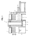
- a coating system embodying the present invention is shown and generally designated by the reference numeral 1.
- the coating system 1 is arranged along a conveyor 2 that conveys cylindrical, conductive cores for forming photoconductive elements in the form of drums.
- the coating system 1 includes a base 3 on which a support shaft 5 is mounted via a rotation mechanism 4.
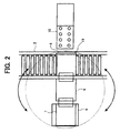
- a first arm 6 and a second arm 7 are located at opposite sides of the support shaft 5 and spaced from each other by an angle of 180°.
- a bath 9 and an end processing device 10 are also located at opposite sides of the support shaft 5 and spaced from each other by an angle of 180°.
- the bath 9 stores a coating liquid 8 for forming photoconductive layers on the cores.
- the arms 6 and 7 include a plurality of core grippers or work grippers 11 each.
- the coating system further includes an elevation mechanism 12 for moving the first arm 6 and second arm 7 up and down.
- the elevation mechanism 12 includes motors 13a and 13b for raising and lowering the arms 6 and 7, respectively.
- Guide shafts 14a and 14b guide the arms 6 and 7, respectively.
- Pulleys 15 and 16 are respectively positioned at the top and the bottom of the guide shaft 14a.
- a plain belt 17 is passed over the pulleys 15 and 16.
- pulleys 15 and 16 are respectively positioned at the top and the bottom of the other guide shaft 14b while a plain belt 17 is passed over the pulleys 15 and 16.
- a balance weight 18 is affixed to each of the belts 17.
- a plurality of conductive cores or works are loaded on a pallet in a vertical position.
- the conveyor 2 conveys the pallet to a core gripping position 19.
- the motor 13a is driven to lower the first arm 6, so that the grippers 11 mounted on the arm 6 grip the conductive cores.
- the motor 13a is then driven in the reverse direction for raising the arm 6.
- the balance weight 18 affixed to the plain belt 17, which moves the arm 16, reduces a load to act on the motor 13a.
- the balance weight 8 reduces vibration to act on the arm 6 more than a timing belt and therefore allows the conductive cores to be raised and lowered without any vibration.
- the rotation mechanism 4 turns the elevation mechanism 12 by 180° to replace the first arm 6 and second arm 7, positioning the arm 6 above the. bath 9.
- the motor 13a is then driven to lower the arm 6 so as to dip the conductive cores held by the core grippers 11 in the coating liquid 8, which is stored in the bath 9.
- the other motor 13b When the next pallet loaded with conductive cores arrives at the core gripping position 19, the other motor 13b is driven to lower the second arm 7, so that the grippers 11 mounted on the arm 7 grip the cores. The motor 13b is then driven in the reverse direction for raising the arm 7 and waits until the end of coating of the cores held by the first arm 6.
- the motor 13a raises the arm 6 away from the bath 9. Subsequently, the rotation mechanism 4 again turns the elevation mechanism 12 by 180° so as to replace the arms 6 and 7 such that the arms 6 and 7 are positioned above the core gripping position 19 and bath 9, respectively. In this condition, the end processing device 10 is slid to a position above the core gripping position 19. Thereafter, the motor 13a again lowers the first arm 6 and allows the end processing device 10 to remove films from the end faces of the cores. At the same time, the motor 13b lowers the second arm 7 so as to dip the cores held by the arm 7 in the coating liquid 8.
- the end processing device 10 removed the films from the end faces of the cores is again slid away from the core gripping position 19. Subsequently, the coated cores held by the first arm 6 are again loaded on the pallet positioned on the conveyor 2. The conveyor 2 then conveys the pallet away from the core gripping position 19. When the next pallet loaded with conductive cores is brought to the core gripping position 19, the core grippers of the arm 6 grip the cores and waits until the end of coating of the cores held by the arm 7. By repeating such a procedure, the system coats consecutive cores and removes films from the end faces of coated cores at the same time.
- the present invention provides a coating system capable of reducing the tact time with a simple construction, and stably coating works while stably removing films from the end faces of coated works to thereby efficiently form high-quality films. Further, the coating system occupies a minimum of space and allows the works with processed end faces to be easily conveyed out of the system. In addition, the coating system reduces the tact time of a production line for producing photoconductive elements for thereby increasing yield.
- the present invention comprises the following embodiments:
Landscapes
- Physics & Mathematics (AREA)
- General Physics & Mathematics (AREA)
- Coating Apparatus (AREA)
- Photoreceptors In Electrophotography (AREA)
- Application Of Or Painting With Fluid Materials (AREA)
Abstract
Description
the conductive cores are dipped in the coating liquid stored in said bath, and then said end processing device processes films formed on end faces of said conductive cores coated with said coating liquid.
Claims (9)
- A coating system comprising:wherein works to be coated and works to be processed by said end processing device (10) are replaced in position with each other to thereby effect coating and end face processing in parallel.a bath (9) storing a coating liquid (8) for coating works;an end processing device (10) for processing films formed on end faces of the works coated with the coating liquid (8); andat least two elevation devices (12) mounted on a single rotatable shaft (5) each for gripping the works and selectively raising or lowering said works;
- The system as claimed in claim 1, wherein said elevation devices (12) are movable independently of each other.
- The system as claimed in claim 1 or 2, wherein said elevation devices (12) comprise two elevation devices mounted on said rotatable shaft (5) at positions spaced by an angle of 180°.
- The system as claimed in any of the preceding claims, wherein said end processing device (10) is movable between an inoperative position outside of an operating range and an operative position where the works are gripped and loaded.
- The system as claimed in any of the preceding claims, wherein said elevation devices (12) each comprise a plain belt (17) to be driven by a motor (13a; 13b) and a balance weight (18) affixed to said plain belt (17).
- The system as claimed in any of the preceding claims, wherein said elevation devices (12) each further comprise work grippers (11) for gripping the works.
- In a system for producing photoconductive elements for electrophotography and comprising a coating system including a bath (9) storing a coating liquid (8) for coating conductive cores, an end processing device (10) for processing films formed on end faces of said conductive cores coated with said coating liquid, and at least two elevation devices (12) mounted on a single rotatable shaft (5) each for gripping said conductive cores and selectively raising or lowering said conductive cores, wherein conductive cores to be coated and conductive cores to be processed by said end processing device (10) are replaced in position with each other to thereby effect coating and end face processing in parallel,
the conductive cores are dipped in the coating liquid (8) stored in said bath (9), and then said end processing device (10) processes films formed on end faces of said conductive cores coated with said coating liquid (8). - A method of producing photoconductive elements for electrophotography, comprising the steps of:causing at least two elevation devices to grip conductive cores; andreplacing the photoconductive elements located at a coating position for coating said photoconductive elements with a coating liquid and the photoconductive elements located at an end processing position for processing films formed on end faces of the photoconductive elements coated, thereby executing coating and end face processing in parallel.
- The method as claimed in claim 8, wherein said elevation devices are movable independently of each other.
Applications Claiming Priority (2)
| Application Number | Priority Date | Filing Date | Title |
|---|---|---|---|
| JP2001133768A JP2002326047A (en) | 2001-05-01 | 2001-05-01 | Coating apparatus and apparatus and method for manufacturing electrophotographic photoreceptor |
| JP2001133768 | 2001-05-01 |
Publications (3)
| Publication Number | Publication Date |
|---|---|
| EP1255165A2 true EP1255165A2 (en) | 2002-11-06 |
| EP1255165A3 EP1255165A3 (en) | 2003-01-29 |
| EP1255165B1 EP1255165B1 (en) | 2008-03-12 |
Family
ID=18981568
Family Applications (1)
| Application Number | Title | Priority Date | Filing Date |
|---|---|---|---|
| EP20020009305 Expired - Lifetime EP1255165B1 (en) | 2001-05-01 | 2002-04-30 | Coating system and system for producing photoconductive elements for electrophotography |
Country Status (3)
| Country | Link |
|---|---|
| EP (1) | EP1255165B1 (en) |
| JP (1) | JP2002326047A (en) |
| DE (1) | DE60225501T2 (en) |
Cited By (2)
| Publication number | Priority date | Publication date | Assignee | Title |
|---|---|---|---|---|
| WO2015084490A1 (en) * | 2013-12-03 | 2015-06-11 | Advenira Enterprises, Inc. | Coating material distribution using simultaneous rotation and vibration |
| CN113634435A (en) * | 2021-08-16 | 2021-11-12 | 浙江凯立特医疗器械有限公司 | Film coating structure for production of implantable biosensor |
Families Citing this family (1)
| Publication number | Priority date | Publication date | Assignee | Title |
|---|---|---|---|---|
| KR100474861B1 (en) * | 2002-11-15 | 2005-03-11 | 이건테크놀로지 주식회사 | A device for applying getter |
Family Cites Families (13)
| Publication number | Priority date | Publication date | Assignee | Title |
|---|---|---|---|---|
| JPS59102780A (en) * | 1982-12-01 | 1984-06-13 | 三菱電機株式会社 | Elevator device |
| JPH0648385B2 (en) * | 1985-03-07 | 1994-06-22 | キヤノン株式会社 | Electrophotographic photoconductor manufacturing equipment |
| JPH0246734U (en) * | 1988-09-22 | 1990-03-30 | ||
| JPH0711821Y2 (en) * | 1989-08-11 | 1995-03-22 | 岩谷産業株式会社 | Partial coating equipment for small articles |
| US5098749A (en) * | 1990-05-04 | 1992-03-24 | Illinois Tool Works Inc. | Workpiece-treating system and related method |
| JP3010374B2 (en) * | 1990-11-15 | 2000-02-21 | コニカ株式会社 | Manufacturing method of electrophotographic photoreceptor |
| JP2903912B2 (en) * | 1992-11-10 | 1999-06-14 | 株式会社ダイフク | In / out transfer device |
| JP3412270B2 (en) * | 1994-07-27 | 2003-06-03 | 株式会社ダイフク | Detecting device for slack of suspension belt of lifting device |
| DE19648341A1 (en) * | 1996-11-22 | 1998-05-28 | Lippert Masch Stahlbau J | Round table glazing machine |
| WO1999043593A1 (en) * | 1998-02-26 | 1999-09-02 | Otis Elevator Company | Elevator system with overhead drive motor |
| JP2000169061A (en) * | 1998-12-03 | 2000-06-20 | Mitsubishi Electric Building Techno Service Co Ltd | Exchange working method of elevator cage constitutional member and its auxiliary tool |
| JP4021086B2 (en) * | 1999-01-28 | 2007-12-12 | 株式会社日立プラントテクノロジー | lift device |
| JP4040248B2 (en) * | 2000-11-10 | 2008-01-30 | 株式会社リコー | Dip coating and coating film removing device for cylindrical substrate for electrophotographic photoreceptor |
-
2001
- 2001-05-01 JP JP2001133768A patent/JP2002326047A/en active Pending
-
2002
- 2002-04-30 DE DE2002625501 patent/DE60225501T2/en not_active Expired - Lifetime
- 2002-04-30 EP EP20020009305 patent/EP1255165B1/en not_active Expired - Lifetime
Cited By (4)
| Publication number | Priority date | Publication date | Assignee | Title |
|---|---|---|---|---|
| WO2015084490A1 (en) * | 2013-12-03 | 2015-06-11 | Advenira Enterprises, Inc. | Coating material distribution using simultaneous rotation and vibration |
| US9272306B2 (en) | 2013-12-03 | 2016-03-01 | Advenira Enterprises, Inc. | Coating material distribution using simultaneous rotation and vibration |
| RU2610496C1 (en) * | 2013-12-03 | 2017-02-13 | Адвенира Энтерпрайзис, Инк. | Coating material spreading by means of simultaneous rotation and vibration |
| CN113634435A (en) * | 2021-08-16 | 2021-11-12 | 浙江凯立特医疗器械有限公司 | Film coating structure for production of implantable biosensor |
Also Published As
| Publication number | Publication date |
|---|---|
| EP1255165B1 (en) | 2008-03-12 |
| DE60225501T2 (en) | 2009-04-23 |
| EP1255165A3 (en) | 2003-01-29 |
| DE60225501D1 (en) | 2008-04-24 |
| JP2002326047A (en) | 2002-11-12 |
Similar Documents
| Publication | Publication Date | Title |
|---|---|---|
| KR101516819B1 (en) | Substrate treatment apparatus | |
| JP6559976B2 (en) | Substrate transfer robot and substrate processing system | |
| CN108028218B (en) | Substrate transfer robot and substrate processing system | |
| CN1736831B (en) | Method and apparatus for transporting substrate carriers within an electronic device manufacturing facility | |
| JPH0778858A (en) | Conveying method and conveying device | |
| CN107785288B (en) | Substrate processing apparatus and substrate processing method | |
| JP4516067B2 (en) | Substrate carry-in / out device and substrate carry-in / out method | |
| EP1255165B1 (en) | Coating system and system for producing photoconductive elements for electrophotography | |
| CN112173981B (en) | Conveyor control device and conveyor control system including the same | |
| JPWO2008133286A1 (en) | Polishing apparatus and program thereof | |
| CN110364421A (en) | A kind of wet etching equipment and wet etching method | |
| JP6677077B2 (en) | Component transfer device and component transfer method | |
| CN114446847A (en) | Wafer transmission system and wafer transmission method | |
| CN115009083A (en) | Battery replacement control method for battery replacement station | |
| KR101172590B1 (en) | Substrate transfer device of chemical mechanical polishing system | |
| JP4040248B2 (en) | Dip coating and coating film removing device for cylindrical substrate for electrophotographic photoreceptor | |
| JP2007311724A (en) | Substrate transport method and substrate processing apparatus | |
| JPH0555345A (en) | Wafer transfer device | |
| JP2006330355A (en) | Method and apparatus for manufacturing electrophotographic photoreceptor | |
| JP2002151566A (en) | Substrate transfer device | |
| JP2995479B2 (en) | Substrate transfer method in vertical heat treatment equipment | |
| CN114551315A (en) | Wafer positioning device and method and semiconductor process equipment | |
| CN116961327B (en) | Copper wire disassembling equipment for motor stator | |
| CN120534715A (en) | Plate conveying device, plate detection system and working method thereof | |
| KR101863190B1 (en) | Substrate treating apparatus and substrate treating method using the same |
Legal Events
| Date | Code | Title | Description |
|---|---|---|---|
| PUAI | Public reference made under article 153(3) epc to a published international application that has entered the european phase |
Free format text: ORIGINAL CODE: 0009012 |
|
| 17P | Request for examination filed |
Effective date: 20020430 |
|
| AK | Designated contracting states |
Kind code of ref document: A2 Designated state(s): AT BE CH CY DE DK ES FI FR GB GR IE IT LI LU MC NL PT SE TR |
|
| AX | Request for extension of the european patent |
Free format text: AL;LT;LV;MK;RO;SI |
|
| PUAL | Search report despatched |
Free format text: ORIGINAL CODE: 0009013 |
|
| RIC1 | Information provided on ipc code assigned before grant |
Free format text: 7G 03G 5/05 A, 7B 05D 1/18 B, 7B 05C 3/09 B |
|
| AK | Designated contracting states |
Designated state(s): AT BE CH CY DE DK ES FI FR GB GR IE IT LI LU MC NL PT SE TR |
|
| AX | Request for extension of the european patent |
Extension state: AL LT LV MK RO SI |
|
| AKX | Designation fees paid |
Designated state(s): DE FR GB |
|
| 17Q | First examination report despatched |
Effective date: 20070207 |
|
| GRAP | Despatch of communication of intention to grant a patent |
Free format text: ORIGINAL CODE: EPIDOSNIGR1 |
|
| GRAS | Grant fee paid |
Free format text: ORIGINAL CODE: EPIDOSNIGR3 |
|
| GRAA | (expected) grant |
Free format text: ORIGINAL CODE: 0009210 |
|
| AK | Designated contracting states |
Kind code of ref document: B1 Designated state(s): DE FR GB |
|
| REG | Reference to a national code |
Ref country code: GB Ref legal event code: FG4D |
|
| REF | Corresponds to: |
Ref document number: 60225501 Country of ref document: DE Date of ref document: 20080424 Kind code of ref document: P |
|
| ET | Fr: translation filed | ||
| PLBE | No opposition filed within time limit |
Free format text: ORIGINAL CODE: 0009261 |
|
| STAA | Information on the status of an ep patent application or granted ep patent |
Free format text: STATUS: NO OPPOSITION FILED WITHIN TIME LIMIT |
|
| 26N | No opposition filed |
Effective date: 20081215 |
|
| REG | Reference to a national code |
Ref country code: FR Ref legal event code: PLFP Year of fee payment: 15 |
|
| REG | Reference to a national code |
Ref country code: FR Ref legal event code: PLFP Year of fee payment: 16 |
|
| PGFP | Annual fee paid to national office [announced via postgrant information from national office to epo] |
Ref country code: DE Payment date: 20170419 Year of fee payment: 16 Ref country code: FR Payment date: 20170419 Year of fee payment: 16 Ref country code: GB Payment date: 20170419 Year of fee payment: 16 |
|
| REG | Reference to a national code |
Ref country code: DE Ref legal event code: R119 Ref document number: 60225501 Country of ref document: DE |
|
| GBPC | Gb: european patent ceased through non-payment of renewal fee |
Effective date: 20180430 |
|
| PG25 | Lapsed in a contracting state [announced via postgrant information from national office to epo] |
Ref country code: DE Free format text: LAPSE BECAUSE OF NON-PAYMENT OF DUE FEES Effective date: 20181101 |
|
| PG25 | Lapsed in a contracting state [announced via postgrant information from national office to epo] |
Ref country code: GB Free format text: LAPSE BECAUSE OF NON-PAYMENT OF DUE FEES Effective date: 20180430 |
|
| PG25 | Lapsed in a contracting state [announced via postgrant information from national office to epo] |
Ref country code: FR Free format text: LAPSE BECAUSE OF NON-PAYMENT OF DUE FEES Effective date: 20180430 |