EP1255144A2 - Dividable optical cable - Google Patents
Dividable optical cable Download PDFInfo
- Publication number
- EP1255144A2 EP1255144A2 EP02396037A EP02396037A EP1255144A2 EP 1255144 A2 EP1255144 A2 EP 1255144A2 EP 02396037 A EP02396037 A EP 02396037A EP 02396037 A EP02396037 A EP 02396037A EP 1255144 A2 EP1255144 A2 EP 1255144A2
- Authority
- EP
- European Patent Office
- Prior art keywords
- optical cable
- forming pipe
- sheath
- optical
- cable according
- Prior art date
- Legal status (The legal status is an assumption and is not a legal conclusion. Google has not performed a legal analysis and makes no representation as to the accuracy of the status listed.)
- Granted
Links
Images


Classifications
-
- G—PHYSICS
- G02—OPTICS
- G02B—OPTICAL ELEMENTS, SYSTEMS OR APPARATUS
- G02B6/00—Light guides; Structural details of arrangements comprising light guides and other optical elements, e.g. couplings
- G02B6/44—Mechanical structures for providing tensile strength and external protection for fibres, e.g. optical transmission cables
- G02B6/4401—Optical cables
- G02B6/4429—Means specially adapted for strengthening or protecting the cables
- G02B6/443—Protective covering
- G02B6/4431—Protective covering with provision in the protective covering, e.g. weak line, for gaining access to one or more fibres, e.g. for branching or tapping
Definitions
- the present invention relates to an optical cable that can be divided later with improved ease.
- numeral 1 indicates an optical ribbon core laminate in which multiple layers of optical fiber ribbon have been laminated together.
- This optical ribbon core laminate 1 is not fixed completely in place inside of the forming pipe 2, but rather is housed with an interval of spacing between itself and forming pipe 2.
- This forming pipe 2 is formed into the shape of a pipe by employing a pipe forming method in which tape, consisting of a rigid plastic film like polyester, polypropylene, polyethylene, polyamide, or fiber reinforced plastic (FRP), is continuously fashioned into a pipe shape. The seams running along the longitudinal direction of this forming pipe 2 are then joined together by meaning of adhesive tape 3.
- tape consisting of a rigid plastic film like polyester, polypropylene, polyethylene, polyamide, or fiber reinforced plastic (FRP)
- the forming pipe 2 is covered with a sheath 4 consisting of polyethylene or plasticizing polyvinyl chloride or the like.
- the formation of sheath 4 is carried out using the usual extruding and cladding method.
- two tension members 5, consisting of fiber-reinforced plastic or steel, brass or other such metal wire, and two rip cords 6, consisting of plastic cords, are embedded in the sheath 4.
- the tension members 5 are disposed opposite one another with the optical ribbon core laminate 1 interposed between them.
- Rip cords 6 are disposed opposite one another with the optical ribbon core laminate 1 interposed between them, and so as to be perpendicular to a line joining the two tension members 5.
- an intermittent filling material (not shown) consisting of a soft hot-melt adhesive is employed to fill the optical cable at intermittent points along the longitudinal direction thereof.
- the sheath 4 When subsequently dividing an optical cable of this design, the sheath 4 is cut open by pulling both rip cords 6, thereby dividing the optical cable into two parts.
- it can be difficult to divide the forming pipe 2 due to its high resistance to tearing, or because it adheres to the sheath 4, for example.
- it can take some time to expose the optical ribbon core laminate 1 inside. In other words, this optical cable does not always demonstrate excellent subsequent dividing.
- the present invention has as its objective to improve the ease with which an optical cable of the above-described design can be divided later.
- This objective is achieved in an optical cable of the above design by enabling a forming pipe fashioned from a plurality of tape to be divided along its longitudinal direction.
- indicators showing the position of the rip cord are formed to the outer periphery of the sheath provided around the forming pipe. These indicators are preferably projections, grooves or an indicator formed by printing or extrusion.
- the forming pipe be filled with hot-melt resin intermittently along its longitudinal direction.
- shock-absorbing material is preferably one in which a non-woven fabric is adhered to the resin film, and a water absorbing powder is affixed to this non-woven cloth.
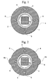
- Fig. 1 is a schematic cross-sectional view showing an example of the optical cable according to the present invention.
- Fig. 2 is a schematic cross-sectional view showing another example of the optical cable according to the present invention.
- Fig. 3 is a schematic cross-sectional view showing another example of the optical cable according to the present invention.
- Fig. 4 is a schematic cross-sectional view showing another example of the optical cable according to the present invention.
- Fig. 5 is a schematic cross-sectional view showing another example of the optical cable according to the present invention.
- Fig. 6 is a schematic cross-sectional view showing another example of the optical cable according to the present invention.
- Fig. 7 is a schematic cross-sectional view showing another example of the optical cable according to the present invention.
- Fig. 8 is a schematic cross-sectional view showing an example of the laminate tape employed in the optical cable according to the present invention.
- Fig. 9 is a schematic cross-sectional view showing a conventional optical cable.
- Fig. 1 shows an example of the optical cable according to the present invention.
- the optical cable of this example differs from the conventional optical cable shown in Fig. 9 in that the forming pipe 2 can be divided in half along its longitudinal direction, there is no adhesive tape 3, and rip cords 6 are disposed inside of the sheath 4 near the seams of the dividable forming pipe 2.
- the dividable forming pipe 2 is made by continuously fashioning two slightly narrow-width laminate tapes so that each has a semi-circular shape in cross section, and then apposing these together.
- the two seams of forming pipe 2 can simply face one another, may be slightly overlapped, or may face each other with a slight spacing in between.
- An adhesive tape such as used in a conventional forming pipe is not employed here, so that the forming pipe 2 can be easily divided into two pieces when subsequently dividing the optical fiber.
- Production of an optical cable with this type of design is carried out in the following order.
- two pieces of laminate tape are continuously fashioned in a manner so as to have a semi-circular shape in cross-section.
- the two laminates are apposed and the optical ribbon core laminate 1 is inserted into the space between the laminates.
- the space is then intermittently filled with a filling material.
- this assembly is relayed to the cross-head die of an extruder.
- the tension members 5 and rip cords 6 By sending the tension members 5 and rip cords 6 into this cross head die, the forming pipe 2 in which the optical ribbon core laminate 1 is housed is covered with an extruded sheath 4, and the tension members 5 and rip cords 6 are embedded at specific positions in the sheath 4.
- the rip cords 6 are pulled to tear open the sheath 4.
- the forming pipe 2 which was already split into two pieces, is divided each part remaining adhered to the respective portions of the sheath 4.
- the division of the sheath 4 and forming pipe 2 is carried out in a single stroke, and the optical ribbon core laminate 1 in the inside of the forming pipe 2 can be exposed quickly and easily.
- Fig. 2 shows another example of an optical cable according to the present invention.
- the optical cable in this example has the same internal structure as the optical cable shown in Fig. 1.
- the rip cords 6 are disposed so as to be in contact with the seams of the dividable forming pipe 2.
- a pair of indicators 4a showing the positions of the rip cords 6 have been formed at symmetrical positions on either side of the rip cords 6 on the outer periphery of the sheath 4.
- These indicators 4a are provided for showing the position of the rip cords 6.
- a pair of projection are formed extending along the longitudinal direction of the optical cable.
- the position of the rip cords 6 can be easily confirmed using the indicators 4a.
- the rip cords 6 can be easily pulled out from the optical cable.
- the indicators 4a form a projection that is thicker than the other parts of the sheath 4.
- the indicators 4a form a projection that is thicker than the other parts of the sheath 4.
- the indicators 4a are not limited to projections as described in this example. Rather, they may also be formed as grooves, may be printed or extruded on the outer periphery of the sheath 4, or may be in the form of lines marked in a different color.
- a method may be employed in which a pigment that is a different color from that of the main body of the sheath 4 is extruded along with the main body of the sheath 4, so that a unitary structure is formed.
- the outer periphery of the sheath 4 around the tension members 5 are evaginated in order to maintain the thickness of the sheath 4 which covers the tension members 5 to avoid the decrease in the mechanical strength of the sheath 4 without thicken the diameter of the optical cable.
- a pair of projection similar to the indicators 4a shown in Fig 2 are formed extending along the longitudinal direction of the optical cable.
- Fig. 3 shows another example of an optical cable according to the present invention.
- the rip cords 6 are also disposed so as to be in contact with the seams of the dividable forming pipe 2.
- a spacer 7 which is in the shape of a cross in cross-section has also been provided in the inside of the forming pipe 2.
- the optical fibers are disposed in the grooves of this spacer 7.
- the spacer 7 grooves are twisted in one direction or in the SZ directions.
- To be twisted in the SZ directions refers to repeatedly alternating the direction in which the groove runs between the S direction and the Z direction when creating a stranded wire by twisting metal wires, in the same manner as conventional SZ twisting.
- the spacer 7 By disposing the spacer 7 in the inside of the forming pipe 2, it is easy to recognize the optical fibers in the optical cable. In addition, since the spacer 7 is disposed in the inside of the forming pipe 2, there is no need to completely fix it in place as in a slot such as employed in the conventional slot-type optical cable. Thus, the optical cable can be made at low cost.
- the shape of the spacer 7 is not limited to a cross in cross-section. Rather, the spacer 7 may also be shaped as a slot in which one or more grooves are formed in one direction or in the SZ direction in the outer peripheral surface of a cylindrically shaped synthetic resin rod.
- Fig. 4 shows another example of an optical cable according to the present invention.
- the rip cords 6 are also disposed so as to come in contact with the seams of the dividable forming pipe 2.
- the optical fiber 8 and paired metal core wire 20 are housed in the inside of the forming pipe 2.
- the paired metal core wire 20 are formed by two stripes of metal core wires 23, in which a conductor 21 is covered by an insulating member 22, with metal core wires 23 twisted together. Copper or aluminum wire may be employed for the conductor 21, with copper being optimally employed typically. Polyethylene, polyvinyl chloride and the like may be cited as examples of the insulating member 22, with polyethylene being preferably employed. It is also acceptable to employ four stripes of metal core wires twisted together, or two or more pairs of metal paired core wires for the paired metal core wire 20.
- optical fiber cores may be used for the optical fiber 8.
- Fig. 5 shows another example of an optical cable according to the present invention.
- the rip cords 6 are also disposed so as to be in contact with the seams of dividable forming pipe 2.
- the optical cable in this example is roughly an ellipse in cross-section, in which the circular form of the cable has been squashed perpendicular to the seams of the forming pipe 2.
- the optical fiber 8 and a coaxial cable 24 are housed in the inside of the forming pipe 2.
- Optical fiber cores, optical fiber cords, optical fiber units or the like may be used for the optical fiber 8 in this example as well.
- optical fibers When installing the optical fibers inside a building, other communications or power lines can be installed at the same time by creating a compound structure including the optical fiber, metal core wires, or the coaxial cables, as shown in Figs. 4 and 5. Thus, improved labor efficiency and lower costs can be achieved.
- Fig. 6 shows another example of an optical cable according to the present invention.
- the rip cords 6 are also disposed so as to be in contact with the seams of the dividable forming pipe 2.
- the outermost layers (the upper and lower layers in the figure) of the optical fiber ribbon core laminate 1 which is housed inside of the forming pipe 2 consist of water absorbent dummy ribbon cores 1b
- the dummy ribbon cores 1b are laminated onto the optical fiber ribbon core laminate 1, and are formed in a unitary manner with the optical fiber ribbon core laminate 1 during its formation.
- a water absorbent resin powder such as polyacrylic resin, polyvinyl alcohol resin, polyacrylamide resin, polyoxyethylene resin or the like, is adhered to the surface of the dummy ribbon cores 1b. As a result, water absorbency is provided to the dummy ribbon cores 1b from this water absorbent resin powder.
- the dummy ribbon cores 1b By providing the dummy ribbon cores 1b to the outermost layers of the optical fiber ribbon core laminate 1, the increase in transmission losses due to direct contact between the forming pipe 2 and the optical fibers disposed at the four corners of the optical fiber ribbon core laminate 1 can be decreased. Further, since the dummy ribbon cores 1b have water absorbent, the optical fiber possesses superior resistance to water.
- a soft hot-melt resin is employed to intermittently fill the forming pipe 2 along the longitudinal direction of the optical cable.
- the optical fibers and the like are supported at various sites along their length and can be housed in the forming pipe 2 without being completely fixed in place.
- subsequent division of the optical cable is easily accomplished.
- Fig. 7 is a cross-sectional view showing another example of an optical cable according to the present invention.
- the rip cords 6 are also disposed so as to be in contact with the seams of the dividable forming pipe 2.
- Yarn 25 is employed as a shock-absorbing material used to fill the inside of the forming pipe 2.
- This yarn 25 is made by forming a water absorbent resin, such as polyethylene fiber, polypropylene fiber, polyacrylic resin, polyvinyl alcohol resin, polyacrylamide resin, polyoxyethylene resin, etc. into fibers, or by adhering these water absorbent materials to another type of fiber. Accordingly, the optical cable of this example has excellent resistance to water.
- the yarn 25 surrounds the optical ribbon core laminate 1 and prevents breakage of the optical ribbon core laminate 1 from external force by restricting its movement in the inside of the forming pipe 2.
- fabrication of the optical cable is simplified, production costs are lowered, and a superior design with respect to ease of subsequent division of the cable is achieved.
- a shock-absorbing layer 26 may be provided on the inner surface of the forming pipe 2, with the optical ribbon core laminate 1 surrounded by this shock-absorbing layer 26.
- a design may be employed for the tapes comprising the forming pipe 2 in which a base 28 consisting of polyethylene terephthalate or the like is adhered on top of a laminate film 27, a non-woven fabric comprising shock-absorbing layer 26 is adhered to the base 28, and a water absorbing powder is affixed to this non-woven cloth.
- this shock-absorbing layer 26 is soft, highly effective at absorbing shocks, and water absorbent.
- the tapes may be comprised of the base alone, the base with a water absorbent powder adhered thereto, the base and a shock-absorbing layer in which the water absorbent powder is adhered to the shock-absorbing layer, or a laminate film adhered to these bases.
- the forming pipe 2 and the sheath 4 undergo melt fusion to tightly adhere to one another when covering the forming pipe 2 with the sheath 4.
- the shock-absorbing layer 26 By using the shock-absorbing layer 26 to hold the optical ribbon core laminate 1 in the inside of the forming pipe 2 in this way, the optical ribbon core laminate 1 can be loosely fixed in place. As a result, the optical cable that is superior with respect to ease of subsequent division thereof is obtained. Moreover, since a hot-melt resin or other such intermittent filler is not needed here, fabrication is simple and costs are reduced. In addition, by providing the shock-absorbing layer 26 with water absorbency, the optical cable is obtained which has superior resistance to water.
- the rip cords 6 are disposed so as to be in contact with the seams of the forming pipe 2. Accordingly, the seams of the forming pipe 2 can be exposed by pulling the rip cords 6 and tearing open the sheath 4.
- the already split forming pipe 2 is divided while adhering to the respective parts of the sheath 4.
- the division of the sheath 4 and the forming pipe 2 is carried out in a single stroke, so that the optical cable core laminate 1 in the forming pipe 2 can be exposed easily and quickly.
- the optical fiber housed inside of the forming pipe 2 is not limited to the optical ribbon core laminate 1. Rather, it is also acceptable to employ a single layer of optical fiber ribbon core, or an optical fiber aggregate in which multiple optical fibers have been gathered together.
- the number of tapes comprising the forming pipe 2 is not limited to two.
- the forming pipe 2 may also have a design in which a plurality of slightly narrow width, rigid tapes to which is adhered a water absorbent resin powder like polyacrylic resin, polyvinylalcohol resin, polyacrylamide resin, polyoxyethylene resin or the like, are employed and continuously fashioned into the shape of a cylinder.
- a water absorbent resin powder like polyacrylic resin, polyvinylalcohol resin, polyacrylamide resin, polyoxyethylene resin or the like.
- the rip cords 6 be positioned near the seams of the forming pipe 2.
- dividing the forming pipe 2 becomes somewhat troublesome. Accordingly, it is practical to dispose the rip cords 6 near the seams.
- division of the forming pipe is carried out at the same time as division of the sheath using the rip cords, so that the operation can be carried out quickly.
Landscapes
- Physics & Mathematics (AREA)
- General Physics & Mathematics (AREA)
- Optics & Photonics (AREA)
- Laying Of Electric Cables Or Lines Outside (AREA)
- Insulated Conductors (AREA)
- Communication Cables (AREA)
- Optical Fibers, Optical Fiber Cores, And Optical Fiber Bundles (AREA)
Abstract
Description
Claims (11)
- An optical cable comprising:optical fibers,a forming pipe for housing said optical fibers,a sheath provided around said forming pipe, andat least one pair of rip cords embedded in said sheath, wherein:said forming pipe is formed using a plurality of tapes so as to be dividable along the longitudinal direction thereof.
- An optical cable according to claim 1 wherein said rip cords are disposed near the seams of said forming pipe.
- An optical cable according to claim 1 wherein indicators showing the position of said rip cords are formed to the outer periphery of said sheath.
- An optical cable according to claim 2 wherein indicators showing the position of said rip cords are formed to the outer periphery of said sheath.
- An optical cable according to claim 3 wherein said indicators are projections, grooves or indicators formed by printing or extrusion.
- An optical cable according to claim 4 wherein said indicators are projections, grooves or indicators formed by printing or extrusion.
- An optical cable according to claim 1 wherein projections covering at least one pair of tension members embedded in said sheath are formed to the outer periphery of said sheath.
- An optical cable according to claim 1 wherein projections covering at least one pair of tension members embedded in said sheath are formed to the outer periphery of said sheath.
- An optical cable according to one of claims 1 through 8 wherein which a hot-melt resin is used to intermittently fill said forming pipe along the longitudinal direction thereof.
- An optical cable according to one of claims 1 through 8 wherein a shock-absorbing material is provided to the inner surface of said forming pipe.
- An optical cable according to claim 10 wherein said shock-absorbing material is one in which a non-woven fabric is adhered to a resin film, and a water absorbing powder is affixed to the non-woven fabric.
Applications Claiming Priority (2)
| Application Number | Priority Date | Filing Date | Title |
|---|---|---|---|
| JP2001130012A JP2002328277A (en) | 2001-04-26 | 2001-04-26 | Optical cable |
| JP2001130012 | 2001-04-26 |
Publications (3)
| Publication Number | Publication Date |
|---|---|
| EP1255144A2 true EP1255144A2 (en) | 2002-11-06 |
| EP1255144A3 EP1255144A3 (en) | 2007-01-17 |
| EP1255144B1 EP1255144B1 (en) | 2008-03-19 |
Family
ID=18978456
Family Applications (1)
| Application Number | Title | Priority Date | Filing Date |
|---|---|---|---|
| EP02396037A Expired - Lifetime EP1255144B1 (en) | 2001-04-26 | 2002-03-22 | Dividable optical cable |
Country Status (5)
| Country | Link |
|---|---|
| US (1) | US6760522B2 (en) |
| EP (1) | EP1255144B1 (en) |
| JP (1) | JP2002328277A (en) |
| CN (1) | CN1177241C (en) |
| HK (1) | HK1050052B (en) |
Cited By (5)
| Publication number | Priority date | Publication date | Assignee | Title |
|---|---|---|---|---|
| EP1351084A1 (en) * | 2002-04-02 | 2003-10-08 | Alcatel | Optical fibre cable and manufacturing method |
| WO2015020924A3 (en) * | 2013-08-09 | 2015-04-16 | Corning Optical Communications LLC | Armored optical fiber cable |
| WO2015057765A1 (en) * | 2013-10-18 | 2015-04-23 | Corning Optical Communications LLC | Optical fiber cable with reinforcement |
| EP3988976A4 (en) * | 2019-06-21 | 2023-04-05 | Fiberhome Telecommunication Technologies Co., Ltd | TIE LAYER-FREE FIBER OPTIC Litz CABLE AND METHOD FOR ITS MANUFACTURE |
| WO2023062549A1 (en) * | 2021-10-11 | 2023-04-20 | Ppc Broadband Fiber Ltd. | Optical fiber cable that provides enhanced sealing and selectively tears so as to provide enhanced access to an optical fiber |
Families Citing this family (34)
| Publication number | Priority date | Publication date | Assignee | Title |
|---|---|---|---|---|
| US8007884B2 (en) * | 2000-10-25 | 2011-08-30 | Synergistic Ventures, Inc. | Irrigation, erosion control, root growth control and clean-up techniques |
| KR100396281B1 (en) * | 2001-08-28 | 2003-09-02 | 삼성전자주식회사 | Loose tube optical ribbon cable |
| JP2004245958A (en) * | 2003-02-12 | 2004-09-02 | Fujikura Ltd | Optical fiber cable and method and apparatus for manufacturing optical fiber cable |
| US8306377B2 (en) * | 2007-11-02 | 2012-11-06 | Nexans | Loose tube optical fiber cable design and method for making the same |
| JP2009229786A (en) * | 2008-03-24 | 2009-10-08 | Sumitomo Electric Ind Ltd | Optical fiber cable |
| WO2010105657A1 (en) * | 2009-03-16 | 2010-09-23 | Prysmian S.P.A. | Optical cable with improved strippability |
| WO2011068163A1 (en) * | 2009-12-02 | 2011-06-09 | 株式会社フジクラ | Optical fiber cable |
| US8885999B2 (en) | 2010-03-19 | 2014-11-11 | Corning Cable Systems Llc | Optical USB cable with controlled fiber positioning |
| WO2011137236A1 (en) | 2010-04-30 | 2011-11-03 | Corning Cable Systems Llc | Fiber optic cables with access features and methods of making fiber optic cables |
| CN103221862B (en) | 2010-10-28 | 2016-10-26 | 康宁光缆系统有限责任公司 | Fiber optic cable with extruded access features and method for making fiber optic cable |
| ES2955526T3 (en) | 2010-11-23 | 2023-12-04 | Corning Optical Communications LLC | Fiber optic cables with access characteristics and manufacturing method |
| EP2718758B1 (en) | 2011-06-10 | 2015-08-12 | Corning Cable Systems LLC | Fiber optic cables allowing fiber translation to reduce bend attenuation |
| US8682124B2 (en) | 2011-10-13 | 2014-03-25 | Corning Cable Systems Llc | Access features of armored flat fiber optic cable |
| US9274302B2 (en) | 2011-10-13 | 2016-03-01 | Corning Cable Systems Llc | Fiber optic cables with extruded access features for access to a cable cavity |
| US9323022B2 (en) | 2012-10-08 | 2016-04-26 | Corning Cable Systems Llc | Methods of making and accessing cables having access features |
| JP5564026B2 (en) * | 2011-10-18 | 2014-07-30 | 株式会社フジクラ | Optical fiber tape core and optical fiber cable storing the optical fiber core |
| US9201208B2 (en) | 2011-10-27 | 2015-12-01 | Corning Cable Systems Llc | Cable having core, jacket and polymeric jacket access features located in the jacket |
| US9176293B2 (en) | 2011-10-28 | 2015-11-03 | Corning Cable Systems Llc | Buffered fibers with access features |
| CN102411177A (en) * | 2011-11-24 | 2012-04-11 | 成都亨通光通信有限公司 | Loose tube type optical cable with semi-dry cable core |
| US8676012B2 (en) | 2012-01-20 | 2014-03-18 | Corning Cable Systems Llc | Fiber optic cable for very-short-distance networks |
| JP5947558B2 (en) * | 2012-02-16 | 2016-07-06 | 株式会社フジクラ | Fiber optic cable |
| JP5746083B2 (en) * | 2012-04-03 | 2015-07-08 | 株式会社フジクラ | Flat optical fiber cable and optical fiber cable drawing method |
| US8909014B2 (en) | 2012-04-27 | 2014-12-09 | Corning Cable Systems Llc | Fiber optic cable with access features and jacket-to-core coupling, and methods of making the same |
| US9170389B2 (en) | 2012-08-28 | 2015-10-27 | Corning Cable Systems Llc | Hybrid fiber optic cable systems |
| EP3090296B1 (en) | 2013-12-30 | 2019-02-27 | Corning Optical Communications LLC | A fiber optic cable with a binder film system |
| JP5719052B1 (en) * | 2014-03-06 | 2015-05-13 | 株式会社フジクラ | Optical cable |
| JP2016057334A (en) * | 2014-09-05 | 2016-04-21 | 昭和電線ケーブルシステム株式会社 | Optical cable |
| JP6738434B2 (en) | 2016-11-17 | 2020-08-12 | 株式会社フジクラ | Optical fiber cable and method of manufacturing optical fiber cable |
| EP3548946A1 (en) * | 2016-11-30 | 2019-10-09 | Corning Optical Communications LLC | Two piece armored optical cables |
| JP6598813B2 (en) * | 2017-03-29 | 2019-10-30 | 古河電気工業株式会社 | Fiber optic cable |
| CN117555093A (en) | 2019-12-11 | 2024-02-13 | 株式会社藤仓 | optic fibre cable |
| US11237346B2 (en) * | 2020-03-31 | 2022-02-01 | Fujikura Ltd. | Optical fiber cable |
| CN111653392A (en) * | 2020-06-12 | 2020-09-11 | 四川鑫电电缆有限公司 | Power cable capable of eliminating siphon effect |
| CN118707676B (en) * | 2024-08-29 | 2024-11-08 | 江苏永鼎股份有限公司 | A high-strength flame-retardant optical cable for communication |
Family Cites Families (12)
| Publication number | Priority date | Publication date | Assignee | Title |
|---|---|---|---|---|
| US3748371A (en) * | 1972-05-18 | 1973-07-24 | Ericsson Telefon Ab L M | Insulated cable with wire for slitting a protective sheath |
| JPH0897714A (en) | 1994-09-29 | 1996-04-12 | Toshiba Corp | Clock signal generation circuit |
| US5642452A (en) * | 1995-02-21 | 1997-06-24 | Sumitomo Electric Lightwave Corp. | Water-blocked optical fiber communications cable |
| US5719353A (en) * | 1995-06-13 | 1998-02-17 | Commscope, Inc. | Multi-jacketed coaxial cable and method of making same |
| JPH11205943A (en) * | 1997-06-30 | 1999-07-30 | Yazaki Corp | Harness tube |
| US5970196A (en) * | 1997-09-22 | 1999-10-19 | Siecor Corporation | Fiber optic protective member with removable section to facilitate separation thereof |
| US6178278B1 (en) * | 1997-11-13 | 2001-01-23 | Alcatel | Indoor/outdoor dry optical fiber cable |
| US6101305A (en) * | 1997-12-15 | 2000-08-08 | Siecor Corporation | Fiber optic cable |
| JP2000137154A (en) | 1998-10-29 | 2000-05-16 | Fujikura Ltd | Optical cable manufacturing method |
| GB9826263D0 (en) * | 1998-11-30 | 1999-01-20 | Pirelli General Plc | Optical fibre cable manufacture |
| US6377738B1 (en) * | 1998-12-04 | 2002-04-23 | Pirelli Cable Corporation | Optical fiber cable and core with a reinforced buffer tube having visible strength members and methods of manufacture thereof |
| US6566606B1 (en) * | 1999-08-31 | 2003-05-20 | Krone, Inc. | Shared sheath digital transport termination cable |
-
2001
- 2001-04-26 JP JP2001130012A patent/JP2002328277A/en active Pending
-
2002
- 2002-03-22 EP EP02396037A patent/EP1255144B1/en not_active Expired - Lifetime
- 2002-03-25 CN CNB021078580A patent/CN1177241C/en not_active Expired - Fee Related
- 2002-03-25 US US10/106,470 patent/US6760522B2/en not_active Expired - Fee Related
-
2003
- 2003-03-21 HK HK03102087.7A patent/HK1050052B/en not_active IP Right Cessation
Cited By (14)
| Publication number | Priority date | Publication date | Assignee | Title |
|---|---|---|---|---|
| EP1351084A1 (en) * | 2002-04-02 | 2003-10-08 | Alcatel | Optical fibre cable and manufacturing method |
| US9791652B2 (en) | 2013-08-09 | 2017-10-17 | Corning Optical Communications LLC | Armored optical fiber cable |
| US9140867B1 (en) | 2013-08-09 | 2015-09-22 | Corning Optical Communications LLC | Armored optical fiber cable |
| US9482839B2 (en) | 2013-08-09 | 2016-11-01 | Corning Cable Systems Llc | Optical fiber cable with anti-split feature |
| WO2015020924A3 (en) * | 2013-08-09 | 2015-04-16 | Corning Optical Communications LLC | Armored optical fiber cable |
| US10254494B2 (en) | 2013-08-09 | 2019-04-09 | Corning Optical Communications LLC | Armored optical fiber cable |
| AU2018236787B2 (en) * | 2013-08-09 | 2019-08-29 | Corning Optical Communications LLC | Armored optical fiber cable |
| US10578820B2 (en) | 2013-08-09 | 2020-03-03 | Corning Optical Communications LLC | Armored optical fiber cable |
| WO2015057765A1 (en) * | 2013-10-18 | 2015-04-23 | Corning Optical Communications LLC | Optical fiber cable with reinforcement |
| US9594226B2 (en) | 2013-10-18 | 2017-03-14 | Corning Optical Communications LLC | Optical fiber cable with reinforcement |
| US11822139B2 (en) | 2013-10-18 | 2023-11-21 | Corning Optical Communications LLC | Optical fiber cable with reinforcement |
| US12210201B2 (en) | 2013-10-18 | 2025-01-28 | Corning Optical Communications LLC | Optical fiber cable with reinforcement |
| EP3988976A4 (en) * | 2019-06-21 | 2023-04-05 | Fiberhome Telecommunication Technologies Co., Ltd | TIE LAYER-FREE FIBER OPTIC Litz CABLE AND METHOD FOR ITS MANUFACTURE |
| WO2023062549A1 (en) * | 2021-10-11 | 2023-04-20 | Ppc Broadband Fiber Ltd. | Optical fiber cable that provides enhanced sealing and selectively tears so as to provide enhanced access to an optical fiber |
Also Published As
| Publication number | Publication date |
|---|---|
| HK1050052B (en) | 2005-05-13 |
| US20020159727A1 (en) | 2002-10-31 |
| EP1255144B1 (en) | 2008-03-19 |
| EP1255144A3 (en) | 2007-01-17 |
| US6760522B2 (en) | 2004-07-06 |
| CN1177241C (en) | 2004-11-24 |
| HK1050052A1 (en) | 2003-06-06 |
| JP2002328277A (en) | 2002-11-15 |
| CN1383014A (en) | 2002-12-04 |
Similar Documents
| Publication | Publication Date | Title |
|---|---|---|
| US6760522B2 (en) | Optical cable having forming tape and rip cords | |
| US6704482B2 (en) | Optical cable | |
| AU2008283668B2 (en) | Optical fiber cable | |
| KR19990078117A (en) | Optical-fiber cable and method of manufacturing the same | |
| GB2105059A (en) | Optical fibre composite aerial cable | |
| EP0023154B1 (en) | Optical fibres cable and method of manufacturing it | |
| JPH11271581A (en) | Optical cable and method of manufacturing the same | |
| US6775445B2 (en) | Optical fiber drop cable | |
| JPH11337783A (en) | Optical cable | |
| JP6082628B2 (en) | Fiber optic cable | |
| AU2022296983A1 (en) | Optical fiber cable and method of manufacturing optical fiber cable | |
| JP2001318286A (en) | Optical fiber cable and combined power / optical cable | |
| GB2227855A (en) | Optical fibre cable | |
| JP2011150166A (en) | Cable connection portion, power and optical fiber composite cable, and cable connection method | |
| JP3592569B2 (en) | Optical cable | |
| JP2001249259A (en) | Optical cable | |
| JPH09259659A (en) | Optical fiber composite water bottom elongated body and manufacturing method thereof | |
| JP2014228821A (en) | Optical fiber cable | |
| JP2002333556A (en) | Optical cable | |
| JP2002303770A (en) | Fiber optic cable | |
| CN101706603A (en) | Clearance filling rope and cable using same | |
| JP5778723B2 (en) | Fiber optic cable | |
| JP6374208B2 (en) | Fiber optic cable | |
| JP2004191506A (en) | Optical cable | |
| JP2002245870A (en) | Composite communication cable |
Legal Events
| Date | Code | Title | Description |
|---|---|---|---|
| PUAI | Public reference made under article 153(3) epc to a published international application that has entered the european phase |
Free format text: ORIGINAL CODE: 0009012 |
|
| 17P | Request for examination filed |
Effective date: 20020327 |
|
| AK | Designated contracting states |
Kind code of ref document: A2 Designated state(s): AT BE CH CY DE DK ES FI FR GB GR IE IT LI LU MC NL PT SE TR |
|
| AX | Request for extension of the european patent |
Free format text: AL;LT;LV;MK;RO;SI |
|
| PUAL | Search report despatched |
Free format text: ORIGINAL CODE: 0009013 |
|
| AK | Designated contracting states |
Kind code of ref document: A3 Designated state(s): AT BE CH CY DE DK ES FI FR GB GR IE IT LI LU MC NL PT SE TR |
|
| AX | Request for extension of the european patent |
Extension state: AL LT LV MK RO SI |
|
| AKX | Designation fees paid |
Designated state(s): FI SE |
|
| REG | Reference to a national code |
Ref country code: DE Ref legal event code: 8566 |
|
| RIN1 | Information on inventor provided before grant (corrected) |
Inventor name: SUEMATSU, MICHIO, C/O FUJIKURA LTD Inventor name: SATOH, YOSHIYASU, C/O FUJIKURA LTD., Inventor name: HASHIMOTO, YOSHIO Inventor name: YAMANAKA, MASAYOSHI, C/O FUJIKURA LTD. Inventor name: MIYAMOTO, MATSUHIRO, C/O FUJIKURA LTD., Inventor name: WATANABE, KOICHIRO, C/O FUJIKURA LTD., Inventor name: OKADA, NAOKI Inventor name: HOGARI KAZUO, C/O NTT INTELLECTUAL PROPERTY CENTER |
|
| 17Q | First examination report despatched |
Effective date: 20060901 |
|
| PUAF | Information related to the publication of a search report (a3 document) modified or deleted |
Free format text: ORIGINAL CODE: 0009199SEPU |
|
| PUAL | Search report despatched |
Free format text: ORIGINAL CODE: 0009013 |
|
| D17D | Deferred search report published (deleted) | ||
| AK | Designated contracting states |
Kind code of ref document: A3 Designated state(s): FI SE |
|
| GRAP | Despatch of communication of intention to grant a patent |
Free format text: ORIGINAL CODE: EPIDOSNIGR1 |
|
| GRAS | Grant fee paid |
Free format text: ORIGINAL CODE: EPIDOSNIGR3 |
|
| RAP1 | Party data changed (applicant data changed or rights of an application transferred) |
Owner name: FUJIKURA, LTD. Owner name: NIPPON TELEGRAPH AND TELEPHONE COMPANY |
|
| GRAA | (expected) grant |
Free format text: ORIGINAL CODE: 0009210 |
|
| RAP1 | Party data changed (applicant data changed or rights of an application transferred) |
Owner name: NIPPON TELEGRAPH AND TELEPHONE CORPORATION Owner name: FUJIKURA, LTD. |
|
| AK | Designated contracting states |
Kind code of ref document: B1 Designated state(s): FI SE |
|
| REG | Reference to a national code |
Ref country code: SE Ref legal event code: TRGR |
|
| PLBE | No opposition filed within time limit |
Free format text: ORIGINAL CODE: 0009261 |
|
| STAA | Information on the status of an ep patent application or granted ep patent |
Free format text: STATUS: NO OPPOSITION FILED WITHIN TIME LIMIT |
|
| 26N | No opposition filed |
Effective date: 20081222 |
|
| PGFP | Annual fee paid to national office [announced via postgrant information from national office to epo] |
Ref country code: FI Payment date: 20100315 Year of fee payment: 9 |
|
| PGFP | Annual fee paid to national office [announced via postgrant information from national office to epo] |
Ref country code: SE Payment date: 20100310 Year of fee payment: 9 |
|
| REG | Reference to a national code |
Ref country code: SE Ref legal event code: EUG |
|
| PG25 | Lapsed in a contracting state [announced via postgrant information from national office to epo] |
Ref country code: FI Free format text: LAPSE BECAUSE OF NON-PAYMENT OF DUE FEES Effective date: 20110322 |
|
| PG25 | Lapsed in a contracting state [announced via postgrant information from national office to epo] |
Ref country code: SE Free format text: LAPSE BECAUSE OF NON-PAYMENT OF DUE FEES Effective date: 20110323 |