EP1255098B1 - Übertragungsflüssigkeit für die Druckmesstechnik und deren Anwendung - Google Patents
Übertragungsflüssigkeit für die Druckmesstechnik und deren Anwendung Download PDFInfo
- Publication number
- EP1255098B1 EP1255098B1 EP02009439A EP02009439A EP1255098B1 EP 1255098 B1 EP1255098 B1 EP 1255098B1 EP 02009439 A EP02009439 A EP 02009439A EP 02009439 A EP02009439 A EP 02009439A EP 1255098 B1 EP1255098 B1 EP 1255098B1
- Authority
- EP
- European Patent Office
- Prior art keywords
- diaphragm
- pressure
- transmission fluid
- pressure transducer
- sensor
- Prior art date
- Legal status (The legal status is an assumption and is not a legal conclusion. Google has not performed a legal analysis and makes no representation as to the accuracy of the status listed.)
- Expired - Lifetime
Links
Images

Classifications
-
- G—PHYSICS
- G01—MEASURING; TESTING
- G01L—MEASURING FORCE, STRESS, TORQUE, WORK, MECHANICAL POWER, MECHANICAL EFFICIENCY, OR FLUID PRESSURE
- G01L19/00—Details of, or accessories for, apparatus for measuring steady or quasi-steady pressure of a fluent medium insofar as such details or accessories are not special to particular types of pressure gauges
- G01L19/0007—Fluidic connecting means
- G01L19/0046—Fluidic connecting means using isolation membranes
-
- G—PHYSICS
- G01—MEASURING; TESTING
- G01L—MEASURING FORCE, STRESS, TORQUE, WORK, MECHANICAL POWER, MECHANICAL EFFICIENCY, OR FLUID PRESSURE
- G01L19/00—Details of, or accessories for, apparatus for measuring steady or quasi-steady pressure of a fluent medium insofar as such details or accessories are not special to particular types of pressure gauges
- G01L19/06—Means for preventing overload or deleterious influence of the measured medium on the measuring device or vice versa
- G01L19/0627—Protection against aggressive medium in general
- G01L19/0645—Protection against aggressive medium in general using isolation membranes, specially adapted for protection
-
- G—PHYSICS
- G01—MEASURING; TESTING
- G01L—MEASURING FORCE, STRESS, TORQUE, WORK, MECHANICAL POWER, MECHANICAL EFFICIENCY, OR FLUID PRESSURE
- G01L7/00—Measuring the steady or quasi-steady pressure of a fluid or a fluent solid material by mechanical or fluid pressure-sensitive elements
- G01L7/02—Measuring the steady or quasi-steady pressure of a fluid or a fluent solid material by mechanical or fluid pressure-sensitive elements in the form of elastically-deformable gauges
- G01L7/04—Measuring the steady or quasi-steady pressure of a fluid or a fluent solid material by mechanical or fluid pressure-sensitive elements in the form of elastically-deformable gauges in the form of flexible, deformable tubes, e.g. Bourdon gauges
Definitions
- the invention relates to the use of polyalphaolefin as pressure transfer fluid, Also referred to as filling liquid, in particular in chemical seals and electrical pressure transmitters.
- An electrical pressure transmitter usually has a Sensor membrane and a separation membrane, which together with a Enclosure limit a closed space for pressure transmission with a transfer fluid or filling fluid is filled.
- Some sensor elements such as piezoresistive sensor elements, their silicon membranes and electrical contacts of the sensor elements in the rule are not resistant to the medium must be of the Media are separated to prevent damage to the sensor element to prevent.
- Pressure transmitters and diaphragm seals are being used Pressure measurement in a variety of different applications and procedures in various industries as before for example, mentions and uses areas of life. consequently There are a very large number of different applications of pressure transmitters and diaphragm seals, in particular in terms of the pressures to be measured as well as in terms of the temperatures of the media or the environment of use. There are also a number of special applications such as. in the food industry, the high demands to the physiological harmlessness in the Equipment and measuring technology used.
- EP-A-0 794 197 describes a direct use of certain polyalphaolefins in food, as well as for oiling of machines used in the food industry.
- the invention is based on the object, a transmission fluid for pressure transmitter and diaphragm seal too find that covers a wide operating temperature range and also suitable for use in the food industry is.
- Transfer fluid a polyalphaolefin used by food legislation is.
- the polyalphaolefin as a transfer fluid also remains applicable in an operating temperature range, in the previously used silicone oil had to be used.
- the polyalphaolefin is from the US Food and Drug Administration (FDA) considered safe for use allowed in food technology and therefore can in pressure transmitters and chemical seals for the food industry be used.
- FDA US Food and Drug Administration
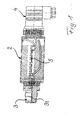
- the pressure transmitter shown in Fig. 1 in a sectional view has an outer housing, generally designated 2, which carries a pressure port 3 at one end and at the other End by means of a plug 4, which serves as an electrical connection connector serves, with other data acquisition devices (not shown) is connected. These data acquisition devices also include a power supply for the pressure transmitter.
- the pressure port 3 is of a Channel 31 is penetrated by the top of the pressure port 3 leads to the sensor element 1.
- the channel 31 can on the side of the pressure port 3 at the top of Pressure transmitter additionally with a flush diaphragm (not shown) connecting the channel 31 from the Medium separates. This procedure is for example in aggressive, or even with solids Messtechnik advantageous. In this case, the channel is 31 filled with transfer fluid.
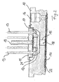
- the sensor element 1 is shown in Fig. 2 in an enlarged Section view shown.
- the sensor element 1 has housing or an annular body 10 with a stepped bore, the is sealed by a sensor carrier 11 to a form first space 21.
- the sensor carrier 11 stops Piezoelectric sensor component 12, which is firmly attached thereto and via wires 17 electrically conductive with contacts 13 is connected, which is tight and electrically isolated in the Sensor carrier 11 are used.
- a membrane 14 edge tightly fastened.
- the membrane 14 and the ring body 10 define a second space 22, which via a channel 15th the stepped bore of the annular body 10 with the of the Ring body 10 and the sensor carrier 11 limited first Room 21 is in communication.
- the membrane 14 causes a change in position or deflection the membrane 14 a volume displacement of a liquid volume from the room 22 into the room 21 or vice versa, whereby the silicon membrane (not shown) of the sensor component 12 is deflected and an electrically detectable Signal supplies.
- the ring body 10 penetrating differential pressure line 19 usually stands with the environment in conjunction and allows the deflection of the silicon membrane (not shown) of the sensor component 12.
- a closable Plug receptacle 16 formed in the annular body 10 opens into the second space 22.
- the sensor element 1 For filling is placed the sensor element 1 in a container and the container is then evacuated. Thereafter, the container with transfer fluid flooded and the transmission fluid penetrates cavity-free in the rooms 21 and 22 and the Channel 15 of the sensor element 1 and fills it. After that is the plug receptacle 16 with a matching plug (not shown) tightly closed.
- the Annular body 10 at the membrane 14 side facing a Membrane bed has, to which the membrane when exceeded the allowable measuring pressures can create a Overstretching or to avoid breakage of the membrane.
- the sensor element may also be a thin-film sensor element which is applied to a sensor membrane in thin-film technology, which is usually made of stainless steel.
- a sensor membrane in thin-film technology which is usually made of stainless steel.
- the separation membrane on the ring body because of the good media resistance Stainless steel is not mandatory.
- the so-called flush membrane at the top of the pressure connection of the pressure transmitter provided so that then the space between the sensor membrane and the flush diaphragm with the transfer fluid must be filled to a functional To obtain pressure transmitter.
- the flush diaphragm can also be connected to the pressure connection of a piezoresistive pressure transmitter be provided, then those of the membranes limited spaces also with transmission fluid to fill.
- Diaphragm Seals are available in membrane, tongue or pipe construction.
- Fig. 3 shows a schematic sectional view of a Diaphragm seal 30, which via a capillary 31st connected to a meter 32.
- the membrane 301 is from the bottom side in Fig. 3 with the medium acted upon and deflected accordingly.
- the change in volume of the membrane 301 in the diaphragm seal 30 limited space causes a shift of a corresponding volume Transfer fluid 18 through the capillary 31 in the measuring element 321 (a tube spring) of the measuring device 32.
- Das Measuring element is deformed according to the volume change and the deformation is read by means of a pointer mechanism displayed.
- the capillary line can also be used as a pipeline serve if the diaphragm seal and the measuring device are made of security-related or organizational reasons be arranged away from each other.
- the viscosity of the transfer fluid is special Meaning too, since the speed of volume shift through the capillary line, which then serves as a trunk serves, the response speed of the meter significantly co-influences.
- the viscosity can be because of the different temperatures at the measuring point (Medium temperature) and at the reading point (ambient temperature) change the viscosity changes in polyalphaolefin However, they are sufficiently small to handle the transmission fluid to achieve good results.
- the meter is also with filled the transmission fluid.
- the non-corrosive Properties of the transfer fluid Polyalphaolefin are therefore also advantageous here and protect the meter.
Landscapes
- Physics & Mathematics (AREA)
- General Physics & Mathematics (AREA)
- Measuring Fluid Pressure (AREA)
Description
| Materialbezeichnung | Polyalphaolefin | |
| Kurzbezeichnung | PAO 6 | |
| Erscheinungsbild | klar | |
| Viskosität bei 40°C | 29,0 bis 32,9 | mm2/s |
| Viskosität bei 100°C | 5,7 bis 6,1 | mm2/s |
| Flammpunkt | mind. 215 | °C |
| Dichte bei 15°C | 810 bis 840 | kg/m3 |
| Stock- oder Fließpunkt | max. -60 | °C |
| Gesamtsäuregehalt | max. 0,05 | mg KOH/g |
Claims (22)
- Verwendung von Polyalphaolefin (PAO 6) als Übertragungsflüssigkeit, die Auslenkungen eines Trennelements zwischen einem Messstoff und der Übertragungsflüssigkeit auf eine Druckmesseinrichtung überträgt, insbesondere in elektrischen Druckmessumformern und Druckmittlern.
- Verwendung von Polyalphaolefin (PAO 6) als Übertragungsflüssigkeit nach Anspruch 1, wobei die Viskosität der Übertragungsflüssigkeit 29,0 bis 32,9 mm2/s bei 40°C und 5,7 bis 6,1 mm2/s bei 100°C beträgt.
- Verwendung von Polyalphaolefin (PAO 6) als Übertragungsflüssigkeit nach Anspruch 1 oder 2, wobei die Dichte der Übertragungsflüssigkeit bei 15°C 810 bis 840 kg/m3 beträgt.
- Verwendung von Polyalphaolefin (PAO 6) als Übertragungsflüssigkeit nach Anspruch 1, 2 oder 3, wobei der Flammpunkt der Übertragungsflüssigkeit mindestens 215°C beträgt.
- Verwendung von Polyalphaolefin (PAO 6) als Übertragungsflüssigkeit nach einem oder mehreren der Ansprüche 1 bis 4, wobei der Fließpunkt der Übertragungsflüssigkeit mindestens -60°C beträgt.
- Verwendung von Polyalphaolefin (PAO 6) als Übertragungsflüssigkeit nach einem oder mehreren der Ansprüche 1 bis 5, wobei der Gesamtsäuregehalt der Übertragungsflüssigkeit maximal 0,05 mgKOH/g beträgt.
- Elektrischer Druckmessumformer mit
einem in einem Gehäuse (10) angebrachten Sensorelement (1), das die Verformung einer dem Sensorelement (1) zugeordneten Sensormembran zur Messung eines an einem Druckanschluss (3) herrschenden Drucks in ein elektrisch erfassbares Signal verwandelt, und
einer Trennmembran (14), die in dem Gehäuse (10) einen geschlossenen Raum (15, 21, 22, 31) zwischen sich und der Sensormembran begrenzt,
dadurch gekennzeichnet, dass
der geschlossene Raum (15, 21, 22, 31) zur Übertragung einer Auslenkung der Trennmembran (14) auf die Sensormembran mit Polyalphaolefin (PAO 6) als Übertragungsflüssigkeit (18) gefüllt ist. - Druckmessumformer nach Anspruch 7, dadurch gekennzeichnet, dass die Trennmembran eine frontbündige Membran ist, die den Druckmessumformer auf der Druckanschlussseite flächenbündig und totraumfrei gegenüber dem Messstoff abschließt.
- Druckmessumformer nach Anspruch 7, dadurch gekennzeichnet, dass die Trennmembran eine in das Gehäuseinnere versetzte Membran (14) ist, so dass die Druckanschlussseite des Druckmessumformergehäuses einen zu der Trennmembran führenden Messstoffkanal (31) ausbildet.
- Druckmessumformer nach Anspruch 7, 8 oder 9, dadurch gekennzeichnet, dass das Sensorelement ein piezoresistives Sensorbauteil (12) ist.
- Druckmessumformer nach Anspruch 7, 8 oder 9, dadurch gekennzeichnet, dass das Sensorelement ein Dünnfilm-Sensorbauteil ist.
- Druckmessumformer nach einem oder mehreren der vorhergehenden Ansprüche 7 bis 11, dadurch gekennzeichnet, dass die Sensormembran eine Kreismembran ist.
- Druckmessumformer nach einem oder mehreren der vorhergehenden Ansprüche 7 bis 11, dadurch gekennzeichnet, dass die Sensormembran eine Kreisringmembran ist.
- Druckmessumformer nach einem oder mehreren der vorhergehenden Ansprüche, dadurch gekennzeichnet, dass die Trennmembran (14) eine gewellte Membran ist.
- Druckmessumformer nach einem oder mehreren der vorhergehenden Ansprüche, dadurch gekennzeichnet, dass das Druckmessumformergehäuse (2) ferner eine Signalaufbereitungselektronik (5) und elektrische Anschlussverbinder (4) aufweist.
- Druckmittler (30) mit
einem Gehäuse, das ein unter Druck elastisch verformbares Trennelement (301) trägt, dessen eine Seite einem Messstoff zugewandt ist und dessen andere Seite einem Raum zugewandt ist, der mit einem Messgerät (32) verbindbar ist,
dadurch gekennzeichnet, dass
der von dem Druckmittlergehäuse, dem Trennelement (301) und dem Messgerät (32) begrenzte Raum mit Polyalphaolefin (PAO 6) als Übertragungsflüssigkeit (18) gefüllt ist, um eine Auslenkung des Trennelements (301) auf das Messgerät zu übertragen. - Druckmittler nach Anspruch 16, dadurch gekennzeichnet, dass das Trennelement eine randseitig am Gehäuse befestigte Membran (301) ist.
- Druckmittler nach Anspruch 16 oder 17, dadurch gekennzeichnet, dass das Trennelement eine randseitig am Gehäuse befestigte doppellagige Membran mit einer dazwischen angeordneten Siebeinlage ist.
- Druckmittler nach einem oder mehreren der vorhergehenden Ansprüche 16 bis 18, dadurch gekennzeichnet, dass das Trennelement eine Kreismembran ist.
- Druckmessumformer nach einem oder mehreren der vorhergehenden Ansprüche 16 bis 18, dadurch gekennzeichnet, dass das Trennelement eine Kreisringmembran ist.
- Druckmessumformer nach einem oder mehreren der vorhergehenden Ansprüche 16 bis 18, dadurch gekennzeichnet, dass das Trennelement eine gewellte Membran ist.
- Druckmittler nach einem oder mehreren der vorhergehenden Ansprüche 16 bis 21, dadurch gekennzeichnet, dass das Gehäuse ein Membranbett zur Abstützung der Membran hat.
Applications Claiming Priority (2)
| Application Number | Priority Date | Filing Date | Title |
|---|---|---|---|
| DE20107260U | 2001-04-27 | ||
| DE20107260U DE20107260U1 (de) | 2001-04-27 | 2001-04-27 | Übertragungsflüssigkeit für die Druckmesstechnik und deren Anwendung |
Publications (2)
| Publication Number | Publication Date |
|---|---|
| EP1255098A1 EP1255098A1 (de) | 2002-11-06 |
| EP1255098B1 true EP1255098B1 (de) | 2004-12-15 |
Family
ID=7956271
Family Applications (1)
| Application Number | Title | Priority Date | Filing Date |
|---|---|---|---|
| EP02009439A Expired - Lifetime EP1255098B1 (de) | 2001-04-27 | 2002-04-25 | Übertragungsflüssigkeit für die Druckmesstechnik und deren Anwendung |
Country Status (3)
| Country | Link |
|---|---|
| US (1) | US6845674B2 (de) |
| EP (1) | EP1255098B1 (de) |
| DE (2) | DE20107260U1 (de) |
Families Citing this family (8)
| Publication number | Priority date | Publication date | Assignee | Title |
|---|---|---|---|---|
| DE102004033813B4 (de) * | 2004-07-12 | 2010-04-08 | Endress + Hauser Gmbh + Co. Kg | Druckmessgerät |
| DE102005002658A1 (de) * | 2005-01-19 | 2006-07-27 | Endress + Hauser Gmbh + Co. Kg | Hydraulischer Druckmittler und Druckaufnehmer bzw. Differenzdruckaufnehmer mit hydraulischem Druckmittler |
| JP2007132697A (ja) * | 2005-11-08 | 2007-05-31 | Denso Corp | 圧力センサ |
| DE102008033337A1 (de) * | 2008-07-16 | 2010-01-21 | Endress + Hauser Gmbh + Co. Kg | Druckmittler und Druckmessgerät mit einem solchen Druckmittler |
| NL2005673C2 (en) * | 2010-11-11 | 2012-05-14 | Badotherm Proces Instr B V | Diaphragm assembly for a pressure sensor, and a pressure sensor provided with such assembly. |
| DE102011088303A1 (de) * | 2011-12-12 | 2013-06-13 | Endress + Hauser Gmbh + Co. Kg | Tubusflanschdruckmittler, Druckmessanordnung mit einem solchen Tubusflanschdruckmittler und Druckmessstelle mit einer solchen Druckmessanordnung |
| WO2017134542A1 (en) * | 2016-02-07 | 2017-08-10 | Rotal Innovative Technologies Ltd. | System and methods for a multi-function pressure device using piezoelectric sensors |
| CN209326840U (zh) | 2018-12-27 | 2019-08-30 | 热敏碟公司 | 压力传感器及压力变送器 |
Family Cites Families (9)
| Publication number | Priority date | Publication date | Assignee | Title |
|---|---|---|---|---|
| DE2712846A1 (de) * | 1976-03-24 | 1977-11-24 | Ict Instr Inc | Messumformer zum messen von druckunterschieden |
| US4466290A (en) * | 1981-11-27 | 1984-08-21 | Rosemount Inc. | Apparatus for conveying fluid pressures to a differential pressure transducer |
| US5050392A (en) * | 1990-06-08 | 1991-09-24 | Mcdonnell Douglas Corporation | Refrigeration system |
| KR930011091B1 (ko) * | 1990-06-08 | 1993-11-20 | 미쯔비시 덴끼 가부시끼가이샤 | 압력 센서 |
| EP0757237B1 (de) * | 1995-08-01 | 2002-04-10 | Endress + Hauser GmbH + Co. | Druckaufnehmer |
| US5869164A (en) * | 1995-11-08 | 1999-02-09 | Rik Medical Llc | Pressure-compensating compositions and pads made therefrom |
| DE69617900T2 (de) * | 1996-03-04 | 2002-04-25 | Exxonmobil Oil Corp., Fairfax | Polyalphaolefine für Nahrungsmitteln und pharmazeutische Verwendungen |
| US6331509B1 (en) * | 1997-01-31 | 2001-12-18 | Elisha Technologies Co Llc | Corrosion resistant lubricants, greases, and gels |
| US6165142A (en) * | 1998-09-21 | 2000-12-26 | Roho, Inc. | Biomedical apparatus |
-
2001
- 2001-04-27 DE DE20107260U patent/DE20107260U1/de not_active Expired - Lifetime
-
2002
- 2002-04-23 US US10/128,067 patent/US6845674B2/en not_active Expired - Lifetime
- 2002-04-25 DE DE50201756T patent/DE50201756D1/de not_active Expired - Lifetime
- 2002-04-25 EP EP02009439A patent/EP1255098B1/de not_active Expired - Lifetime
Also Published As
| Publication number | Publication date |
|---|---|
| DE50201756D1 (de) | 2005-01-20 |
| US6845674B2 (en) | 2005-01-25 |
| US20020178824A1 (en) | 2002-12-05 |
| EP1255098A1 (de) | 2002-11-06 |
| DE20107260U1 (de) | 2001-08-16 |
Similar Documents
| Publication | Publication Date | Title |
|---|---|---|
| DE10196145B3 (de) | Druckwandler mit verbessertem Isolatorsystem | |
| DE102004060647B4 (de) | Fernprozessdichtung mit verbesserter Stabilität in anspruchsvollen Anwendungen | |
| DE69417247T2 (de) | Drucküberträger mit isoliermembran | |
| DE69123603T2 (de) | Isolator für druckübertrager | |
| DE102013100889B4 (de) | Druckdetektor | |
| DE3850661T2 (de) | Modularer überträger. | |
| EP1618362B1 (de) | Druckaufnehmer mit temperaturkompensation | |
| EP2659248B1 (de) | Drucksensor mit kompressiblem element | |
| DE102008019054A1 (de) | Differenzdrucksensor | |
| DE69006925T2 (de) | Hochdruckwandler. | |
| DE19949831B4 (de) | Membrandruckmittler | |
| DE102018110655A1 (de) | Integrierter Druck- und Temperatursensor | |
| EP1425563B1 (de) | Druckmessgerät | |
| DE10200779A1 (de) | Druckmittler mit Modul zur Erkennung von Membranbrüchen und Modul zur Erkennung von Membranbrüchen | |
| DE102016124775A1 (de) | Druckmessaufnehmer mit hydraulischem Druckmittler | |
| EP1255098A1 (de) | Übertragungsflüssigkeit für die Druckmesstechnik und deren Anwendung | |
| DE102014119407A1 (de) | Differenzdrucksensor und Differenzdruckmessaufnehmer mit einem solchen Differenzdrucksensor | |
| EP2333508B1 (de) | Druckmittler mit Temperatursensor | |
| DE102012102020A1 (de) | Mikromechanisches Messelement | |
| DE102015101323A1 (de) | Drucksensor ohne Trennmembran | |
| DE10162044B4 (de) | Druckmessaufnehmer | |
| WO2003004984A1 (de) | Druckmittler mit vorrichtung zur erkennung von membranbrüchen und anschlussadapter mit vorrichtung zur erkennung von membranbrüchen | |
| DE102014211928A1 (de) | Drucksensor zur Erfassung eines Drucks eines fluiden Mediums | |
| EP3237866B1 (de) | Druckwandler und verfahren zum betreiben eines solchen druckwandlers | |
| DE102021120690A1 (de) | Drucksensoranordnung |
Legal Events
| Date | Code | Title | Description |
|---|---|---|---|
| PUAI | Public reference made under article 153(3) epc to a published international application that has entered the european phase |
Free format text: ORIGINAL CODE: 0009012 |
|
| AK | Designated contracting states |
Kind code of ref document: A1 Designated state(s): AT BE CH CY DE DK ES FI FR GB GR IE IT LI LU MC NL PT SE TR |
|
| AX | Request for extension of the european patent |
Free format text: AL;LT;LV;MK;RO;SI |
|
| RIN1 | Information on inventor provided before grant (corrected) |
Inventor name: BECKER, ROMAN Inventor name: PETTER, PETER Inventor name: PLEYER, JUERGEN Inventor name: KALISCH, ABRECHT |
|
| 17P | Request for examination filed |
Effective date: 20021209 |
|
| AKX | Designation fees paid |
Designated state(s): CH DE FR GB IT LI |
|
| 17Q | First examination report despatched |
Effective date: 20040115 |
|
| GRAP | Despatch of communication of intention to grant a patent |
Free format text: ORIGINAL CODE: EPIDOSNIGR1 |
|
| GRAS | Grant fee paid |
Free format text: ORIGINAL CODE: EPIDOSNIGR3 |
|
| GRAA | (expected) grant |
Free format text: ORIGINAL CODE: 0009210 |
|
| AK | Designated contracting states |
Kind code of ref document: B1 Designated state(s): CH DE FR GB IT LI |
|
| REG | Reference to a national code |
Ref country code: GB Ref legal event code: FG4D Free format text: NOT ENGLISH Ref country code: CH Ref legal event code: EP |
|
| REG | Reference to a national code |
Ref country code: CH Ref legal event code: NV Representative=s name: E. BLUM & CO. PATENTANWAELTE |
|
| GBT | Gb: translation of ep patent filed (gb section 77(6)(a)/1977) |
Effective date: 20041215 |
|
| REG | Reference to a national code |
Ref country code: IE Ref legal event code: FG4D Free format text: GERMAN |
|
| REF | Corresponds to: |
Ref document number: 50201756 Country of ref document: DE Date of ref document: 20050120 Kind code of ref document: P |
|
| ET | Fr: translation filed | ||
| PLBE | No opposition filed within time limit |
Free format text: ORIGINAL CODE: 0009261 |
|
| STAA | Information on the status of an ep patent application or granted ep patent |
Free format text: STATUS: NO OPPOSITION FILED WITHIN TIME LIMIT |
|
| 26N | No opposition filed |
Effective date: 20050916 |
|
| REG | Reference to a national code |
Ref country code: CH Ref legal event code: PFA Owner name: WIKA ALEXANDER WIEGAND GMBH & CO.KG Free format text: WIKA ALEXANDER WIEGAND GMBH & CO.KG#ALEXANDER-WIEGAND-STRASSE#63911 KLINGENBERG/MAIN (DE) -TRANSFER TO- WIKA ALEXANDER WIEGAND GMBH & CO.KG#ALEXANDER-WIEGAND-STRASSE#63911 KLINGENBERG/MAIN (DE) |
|
| REG | Reference to a national code |
Ref country code: FR Ref legal event code: PLFP Year of fee payment: 15 |
|
| REG | Reference to a national code |
Ref country code: FR Ref legal event code: PLFP Year of fee payment: 16 |
|
| REG | Reference to a national code |
Ref country code: FR Ref legal event code: PLFP Year of fee payment: 17 |
|
| PGFP | Annual fee paid to national office [announced via postgrant information from national office to epo] |
Ref country code: CH Payment date: 20200423 Year of fee payment: 19 Ref country code: DE Payment date: 20200423 Year of fee payment: 19 Ref country code: FR Payment date: 20200421 Year of fee payment: 19 |
|
| PGFP | Annual fee paid to national office [announced via postgrant information from national office to epo] |
Ref country code: GB Payment date: 20200423 Year of fee payment: 19 Ref country code: IT Payment date: 20200423 Year of fee payment: 19 |
|
| REG | Reference to a national code |
Ref country code: DE Ref legal event code: R082 Ref document number: 50201756 Country of ref document: DE Representative=s name: RWZH RECHTSANWAELTE WACHINGER ZOEBISCH PARTNER, DE |
|
| REG | Reference to a national code |
Ref country code: DE Ref legal event code: R119 Ref document number: 50201756 Country of ref document: DE |
|
| GBPC | Gb: european patent ceased through non-payment of renewal fee |
Effective date: 20210425 |
|
| PG25 | Lapsed in a contracting state [announced via postgrant information from national office to epo] |
Ref country code: DE Free format text: LAPSE BECAUSE OF NON-PAYMENT OF DUE FEES Effective date: 20211103 Ref country code: FR Free format text: LAPSE BECAUSE OF NON-PAYMENT OF DUE FEES Effective date: 20210430 Ref country code: GB Free format text: LAPSE BECAUSE OF NON-PAYMENT OF DUE FEES Effective date: 20210425 Ref country code: LI Free format text: LAPSE BECAUSE OF NON-PAYMENT OF DUE FEES Effective date: 20210430 Ref country code: CH Free format text: LAPSE BECAUSE OF NON-PAYMENT OF DUE FEES Effective date: 20210430 |
|
| PG25 | Lapsed in a contracting state [announced via postgrant information from national office to epo] |
Ref country code: IT Free format text: LAPSE BECAUSE OF NON-PAYMENT OF DUE FEES Effective date: 20200425 |
|
| PG25 | Lapsed in a contracting state [announced via postgrant information from national office to epo] |
Ref country code: IT Free format text: LAPSE BECAUSE OF NON-PAYMENT OF DUE FEES Effective date: 20210425 |