EP1255059A2 - Center differential unit and planetary gear - Google Patents
Center differential unit and planetary gear Download PDFInfo
- Publication number
- EP1255059A2 EP1255059A2 EP02252930A EP02252930A EP1255059A2 EP 1255059 A2 EP1255059 A2 EP 1255059A2 EP 02252930 A EP02252930 A EP 02252930A EP 02252930 A EP02252930 A EP 02252930A EP 1255059 A2 EP1255059 A2 EP 1255059A2
- Authority
- EP
- European Patent Office
- Prior art keywords
- pinion
- sun gear
- shaft
- mpa
- carrier
- Prior art date
- Legal status (The legal status is an assumption and is not a legal conclusion. Google has not performed a legal analysis and makes no representation as to the accuracy of the status listed.)
- Withdrawn
Links
Images


Classifications
-
- F—MECHANICAL ENGINEERING; LIGHTING; HEATING; WEAPONS; BLASTING
- F16—ENGINEERING ELEMENTS AND UNITS; GENERAL MEASURES FOR PRODUCING AND MAINTAINING EFFECTIVE FUNCTIONING OF MACHINES OR INSTALLATIONS; THERMAL INSULATION IN GENERAL
- F16H—GEARING
- F16H48/00—Differential gearings
- F16H48/20—Arrangements for suppressing or influencing the differential action, e.g. locking devices
- F16H48/22—Arrangements for suppressing or influencing the differential action, e.g. locking devices using friction clutches or brakes
-
- F—MECHANICAL ENGINEERING; LIGHTING; HEATING; WEAPONS; BLASTING
- F16—ENGINEERING ELEMENTS AND UNITS; GENERAL MEASURES FOR PRODUCING AND MAINTAINING EFFECTIVE FUNCTIONING OF MACHINES OR INSTALLATIONS; THERMAL INSULATION IN GENERAL
- F16H—GEARING
- F16H48/00—Differential gearings
- F16H48/06—Differential gearings with gears having orbital motion
- F16H48/10—Differential gearings with gears having orbital motion with orbital spur gears
-
- B—PERFORMING OPERATIONS; TRANSPORTING
- B60—VEHICLES IN GENERAL
- B60K—ARRANGEMENT OR MOUNTING OF PROPULSION UNITS OR OF TRANSMISSIONS IN VEHICLES; ARRANGEMENT OR MOUNTING OF PLURAL DIVERSE PRIME-MOVERS IN VEHICLES; AUXILIARY DRIVES FOR VEHICLES; INSTRUMENTATION OR DASHBOARDS FOR VEHICLES; ARRANGEMENTS IN CONNECTION WITH COOLING, AIR INTAKE, GAS EXHAUST OR FUEL SUPPLY OF PROPULSION UNITS IN VEHICLES
- B60K17/00—Arrangement or mounting of transmissions in vehicles
- B60K17/34—Arrangement or mounting of transmissions in vehicles for driving both front and rear wheels, e.g. four wheel drive vehicles
- B60K17/344—Arrangement or mounting of transmissions in vehicles for driving both front and rear wheels, e.g. four wheel drive vehicles having a transfer gear
- B60K17/346—Arrangement or mounting of transmissions in vehicles for driving both front and rear wheels, e.g. four wheel drive vehicles having a transfer gear the transfer gear being a differential gear
- B60K17/3462—Arrangement or mounting of transmissions in vehicles for driving both front and rear wheels, e.g. four wheel drive vehicles having a transfer gear the transfer gear being a differential gear with means for changing distribution of torque between front and rear wheels
-
- F—MECHANICAL ENGINEERING; LIGHTING; HEATING; WEAPONS; BLASTING
- F16—ENGINEERING ELEMENTS AND UNITS; GENERAL MEASURES FOR PRODUCING AND MAINTAINING EFFECTIVE FUNCTIONING OF MACHINES OR INSTALLATIONS; THERMAL INSULATION IN GENERAL
- F16H—GEARING
- F16H48/00—Differential gearings
- F16H48/06—Differential gearings with gears having orbital motion
- F16H48/10—Differential gearings with gears having orbital motion with orbital spur gears
- F16H2048/106—Differential gearings with gears having orbital motion with orbital spur gears characterised by two sun gears
-
- Y—GENERAL TAGGING OF NEW TECHNOLOGICAL DEVELOPMENTS; GENERAL TAGGING OF CROSS-SECTIONAL TECHNOLOGIES SPANNING OVER SEVERAL SECTIONS OF THE IPC; TECHNICAL SUBJECTS COVERED BY FORMER USPC CROSS-REFERENCE ART COLLECTIONS [XRACs] AND DIGESTS
- Y10—TECHNICAL SUBJECTS COVERED BY FORMER USPC
- Y10S—TECHNICAL SUBJECTS COVERED BY FORMER USPC CROSS-REFERENCE ART COLLECTIONS [XRACs] AND DIGESTS
- Y10S475/00—Planetary gear transmission systems or components
- Y10S475/901—Particular material
- Y10S475/902—Nonmetallic
-
- Y—GENERAL TAGGING OF NEW TECHNOLOGICAL DEVELOPMENTS; GENERAL TAGGING OF CROSS-SECTIONAL TECHNOLOGIES SPANNING OVER SEVERAL SECTIONS OF THE IPC; TECHNICAL SUBJECTS COVERED BY FORMER USPC CROSS-REFERENCE ART COLLECTIONS [XRACs] AND DIGESTS
- Y10—TECHNICAL SUBJECTS COVERED BY FORMER USPC
- Y10S—TECHNICAL SUBJECTS COVERED BY FORMER USPC CROSS-REFERENCE ART COLLECTIONS [XRACs] AND DIGESTS
- Y10S74/00—Machine element or mechanism
- Y10S74/10—Polymer digest - plastic gears
Definitions
- the present invention relates to a center differential unit including a planetary gear, and particularly to a center differential unit containing a planetary gear used for effectively transmitting power from an engine to driving wheels of a vehicle, which can produce a sufficient differential torque and has excellent durability.
- a center differential unit In a four wheel drive, power from an engine is transmitted to front and rear wheels usually by a center differential unit. In other words, power from the engine is first transmitted to a transmission by way of a clutch. The transmission output is divided by a center differential unit and transmitted to a front differential unit and a rear differential unit. Torque decelerated by the front and rear differential units is conveyed respectively to the front and rear wheels.
- the center differential unit of a planetary gear type is widely used since it is relatively compact and changes in torque delivery to the front and rear wheels are easily controlled.
- Japanese Patent 2652715 discloses a four wheel drive with a center differential unit having a planetary gear.
- the center differential unit will now be explained by referring to a schematic cross section of a center differential unit shown in Fig. 5 and a schematic diagram in Fig. 6.
- An output shaft 101 is connected with a rear drive shaft 102, which transmits power to a rear differential unit by way of a propeller shaft.
- the output shaft 101 and the rear drive shaft 102 are provided to rotate coaxially via bushings 103 and thrust bearings 104.
- a reduction gear 105 is supported by the output shaft 101 via the bushings 103 and rotates on the output shaft 101.
- the reduction gear 105 and the output shaft 101 are supported on a gearbox casing 100 by ball bearings 106.
- a center differential unit 110 is provided over the output shaft 101, the rear drive shaft 102 and the reduction gear 105 coaxially therewith.
- the reduction gear 105 meshes with a reduction gear 108 provided on a front drive shaft 107.
- the front drive shaft 107 functions to transmit power to a front differential unit.
- the center differential unit 110 includes a large diameter sun gear 111 on the output shaft 101 of a transmission on the input side, a small diameter sun gear 112 on the rear drive shaft 102 on the output side, a small diameter pinion 113 meshed with the large diameter sun gear 111, and a large diameter pinion 114 meshed with the small diameter sun gear 112.
- the small diameter pinion 113 and the large diameter pinion 114 are provided on a single pinion member 115.
- a supporting plate 117 for a carrier 116 is attached to the rear drive shaft 102 by way of a ball bearing 118.
- the supporting plate 117 and the reduction gear 105 are united as an integral body, and a pinion shaft 119 extends over the supporting plate 117 and the reduction gear 105.
- the pinion member 115 is supported by the pinion shaft 119 having needle bearings 120 therebetween. Both ends of the pinion member 115 are supported on the reduction gear 105 and the supporting plate 117 by a thrust washer 122 interposed therebetween.
- An oil supply hole 121 is perforated on the pinion shaft for supplying oil to the needle bearings 120.
- For the pinion shaft 119 high-carbon steel or case-hardened steel which has been subjected to a thermal treatment for hardening the surface is used .
- the differential function is attained by using the large diameter sun gear 111 and the small diameter sun gear 112 with an appropriate number of teeth.
- a disproportional torque ratio on the rear wheels is provided by appropriately distributing the output torque of the transmission. This is achieved by appropriately setting the distance from the meshing point of the large diameter sun gear 111 and the small diameter pinion 113 to the center of the large diameter sun gear 111, and the distance from the meshing point of the small diameter sun gear 112 and the large diameter pinion 114 to the center of the small diameter sun gear 112.
- helical gears for the large diameter sun gear 111, small diameter sun gear 112, small diameter pinion 113 and large diameter pinion 114 so as to generate a thrust load.
- the thrust load causes friction between the edges of the thrust washer 122 and the pinion member 115.
- force resulting from a separation load and a tangential load is applied to the small diameter pinion 113, large diameter pinion 114 and a contacting face between the pinion member 115 and the pinion shaft 119 (needle bearings 120). Accordingly, frictional force is generated on the needle bearings 120.
- a differential control mechanism is provided.
- a radial load is applied to the pinion member 115 depending upon an input torque.
- the needle bearings 120 are provided as bearings for the pinion member 115.
- the needle bearings 120 can be replaced by bushings.
- the needle bearing 120 is durable against a large load, but has a small frictional resistance, since it is a rolling bearing.
- the bushings contact with the pinion member 115 by sliding therebetween. Therefore, the bushing has a large frictional resistance, but a seizure will occur when lubricating oil is insufficiently supplied. Accordingly, it is difficult to take an appropriate countermeasure when large torque for reducing differential action is required based on a load when traveling for instance on a muddy road or a road with a bad surface condition.
- a paper material which is usually used as a friction material for a multi-plate clutch for an automatic transmission, by interposing the paper material between the pinion shaft 119 and the pinion member 115.
- the paper material is not suitable for practical use when lubricating oil containing an additive of a mineral material is used for the differential gear. This is because the durability of the paper friction material is largely decreased due to absorption of such oil.
- the first object of the present invention can also be achieved by the center differential unit of the planetary gear type, wherein the pinion shaft is made entirely of carbon/carbon composite.
- a second object of the present invention is to provide the center differential unit which provides torque for reducing differential action with an improved reliability with efficiently maintaining a sufficient frictional force between the pinion shaft and the pinion member contained in the planetary gear, wherein force resulting from a separation load and a tangential load generated at a meshing point of the first sun gear and the first pinion and a meshing point of the second sun gear and the second pinion is applied to the pinion shaft.
- a third object of the present invention is to provide the center differential unit which provides a larger quantity of torque for reducing the differential action, wherein the first sun gear, the second sun gear, the first pinion and the second pinion are helical gears, a thrust load generated at a meshing point of the first sun gear and the first pinion, and a thrust load generated at a meshing point of the second sun gear and the second pinion cause frictional force between the second sun gear and the carrier.
- a fourth object of the present invention is to provide a center differential unit of a planetary type which provides torque for reducing differential action corresponding to an input torque with maintaining a stable function of a planetary gear contained therein and a sufficient frictional force between a pinion shaft and a pinion member without further providing a bearing or a bushing as a separate member therebetween and by efficiently eliminating a seizure therebetween, comprising a carrier; a first sun gear for receiving a output from a transmission and positioned interiorly of the carrier; a second sun gear provided on an output side with respect to the first sun gear and positioned interiorly of the carrier; a first pinion meshing with the first sun gear; a second pinion meshing with the second sun gear; a pinion member carrying the first pinion and the second pinion therearound, the pinion member having a shaft-receiving hole; a bearing made of carbon/carbon composite provided in the shaft-receiving hole; and a pinion shaft made of a steel material, the pinion shaft supported by the carrier
- a fifth object of the present invention is to provide the center differential unit which provides torque for reducing differential action with an improved reliability with efficiently maintaining a sufficient frictional force between the pinion shaft and the pinion member contained in the planetary gear, wherein force resulting from a separation load and a tangential load generated at a meshing point of the first sun gear and the first pinion and a meshing point of the second sun gear and the second pinion is applied to the pinion shaft.
- a sixth object of the present invention is to provide the center differential unit which provides larger quantity of torque for reducing differential action wherein the first sun gear, the second sun gear, the first pinion and the second pinion are helical gears, a thrust load generated at a meshing point of the first sun gear and the first pinion, and a thrust load generated at a meshing point of the second sun gear and the second pinion cause frictional force between the second sun gear and the carrier.
- a seventh object of the present invention is to provide the center differential unit containing a planetary gear having a smaller member, wherein the carbon/carbon composite has a bending strength in the range of 200 MPa to 1200 MPa, a compressive strength in the range of 100 MPa to 800 MPa, and an interlaminar shear strength in the range of 20 MPa to 600 MPa.
- An eighth object of the present invention is to provide a planetary gear which functions in a stable manner and is light in weight and simple in structure by having a sufficient frictional force between a pinion shaft and a pinion member without providing a bearing or a bushing therebetween and efficiently eliminating a seizure therebetween, comprising a carrier; a sun gear provided interiorly of the carrier; a pinion meshing with the sun gear; a pinion member carrying the pinion therearound, the pinion member having a shaft-receiving hole; and a pinion shaft having at least a surface of carbon/carbon composite, the pinion shaft supported by the carrier and directly supporting the pinion member so as to rotate by being inserted into the shaft-receiving hole of the pinion member.
- the eighth object of the present invention can also be achieved by the planetary gear wherein the pinion shaft is made entirely of carbon/carbon composite.
- a ninth object of the present invention is to provides a planetary gear which is light in weight and simple in structure by maintaining a sufficient frictional force between a pinion shaft and a pinion member without further providing a bearing or a bushing as a separate member therebetween and efficiently eliminating a seizure therebetween, comprising a carrier; a sun gear provided interiorly of the carrier; a pinion meshing with the sun gear; a pinion member carrying the pinion therearound, the pinion member having a shaft-receiving hole; a bearing made of carbon/carbon composite provided in the shaft-receiving hole; and a pinion shaft made of a steel material, the pinion shaft supported by the carrier and directly supporting the pinion member so as to rotate by being inserted into the shaft-receiving hole of the pinion member.
- a tenth object of the present invention is to provide the planetary gear having a smaller member, wherein the carbon/carbon composite has a bending strength in the range of 200 MPa to 1200 MPa, a compressive strength in the range of 100 MPa to 800 MPa, and an interlaminar shear strength in the range of 20 MPa to 600 MPa.
- a manual transmission is used.
- Fig. 1 is a schematic diagram of the transmission
- Fig. 2 is a schematic cross section of a center differential unit
- Fig. 3 is a perspective view of the center differential unit.
- Fig. 1 shows that a transmission casing 1, a transfer casing 2 and an extension casing 3 are connected.
- An engine 10 has a crank shaft 11 connected to a clutch 13 via a flywheel 12, and an intermediate shaft 14 extends from the clutch 13 to a sub-transmission 15.
- a constant mesh type counter gear mechanism 17, and a synchronizing mechanism 18 are provided between the intermediate shaft 14 and an input shaft 16.
- the input shaft 16 extends into a manual transmission 30.
- An output shaft 19 of the manual transmission 30 is provided in parallel with the input shaft 16.
- the input shaft 16 is led into a center differential unit 50 contained in the extension casing 3.
- the output shaft 19 has a cylindrical shape, and a front drive shaft 20 contains the output shaft 19.
- the center differential unit 50 is connected with a front differential unit 21 provided in the sub-transmission 15 at a bottom part thereof by way of the center differential unit 50. Torque is conveyed from the front differential unit 21 to the front wheels.
- a rear drive shaft 23 is arranged in the extension casing 3 at the same height as the input shaft 16 in the manual transmission 30.
- a rear output shaft 56 and the rear drive shaft 23 are linked with each other by way of a pair of transfer gears 24, 25. Torque from the rear drive shaft 23 is transmitted to a propeller shaft 26, a rear differential unit 27 and the rear wheels.
- the manual transmission 30 is a constant mesh type, and a first gear train 31, a second gear train 32, a third gear train 33, a fourth gear train 34, a fifth gear train 35, and synchronizing mechanisms 36, 37 and 38 are arranged over the input shaft 16 and the output shaft 19 provided in parallel with each other. Further, a reverse gear train 39 is positioned between the first gear train 31 and the second gear train 32. By selectively operating the synchronizing mechanisms 36, 37 and 38, the first to the fifth speed are selected. The reverse gear train 39 provides reverse drive.
- the center differential unit 50 contains a center differential input shaft 52, a front output shaft 54 and a rear output shaft 56.
- the center differential input shaft 52 has a cylindrical shape and one end of the center differential input shaft 52 covers an outer surface of the output shaft 19 at an end by a spline connection through an intermediate member 51.
- the front output shaft 54 also has a cylindrical shape and is contained in the hollow portion of the center differential input shaft 52.
- One end of the front output shaft 54 is connected with the front drive shaft 20 so as to cover an end outer surface of the front drive shaft 20 by a spline connection having an intermediate member therebetween.
- the front output shaft 54 contains therein a top portion of the rear output shaft 56.
- the center differential input shaft 52, the front output shaft 54 and the rear output shaft 56 coaxially rotate on each other.
- a large diameter sun gear 60 is provided at a base end of the center differential input shaft 52 as an integral body.
- a small diameter pinion 61 is in mesh with the large diameter sun gear 60.
- a small diameter sun gear 63 is linked with the rear output shaft 56 by a spline connection so as to be provided at an intermediate part of the output shaft 56.
- a large diameter pinion 64 is in mesh with the small diameter sun gear 63.
- the small diameter pinion 61 and the large diameter pinion 64 are formed integrally with a hollow pinion member 65 which has a hole 65a for receiving a pinion shaft 67.
- the first and large diameter pinions 61 and 64 are supported on the pinion shaft 67 fixed to a carrier 66.
- the center differential input shaft 52 is inserted from the front to the carrier 66, and the rear output shaft 56 is inserted from the back so as to rotate.
- the carrier 66 contains the large diameter sun gear 60 and the small diameter sun gear 63 at an intermediate space as shown in Fig. 3.
- a planetary gear is structured by the provision of the pinion shaft 67 with the small diameter pinion 61 meshed with the large diameter sun gear 60 and the large diameter pinion 64 with the small diameter sun gear 63.
- a carbon/carbon composite (hereinafter referred to as C/C composite) is used for the pinion shaft 67.
- the C/C composite is a material prepared by impregnating carbon fibers, carbon textile or carbon filament/yarn with a thermosetting resin or a thermoplastic resin to obtain an impregnated material, followed by calcinating the impregnated material at a high temperature under a high pressure.
- the C/C composite is prepared by reinforcing a carbon matrix with carbon fibers.
- the thus obtained graphited C/C composite is used for the pinion shaft 67.
- the conventional C/C composite has a bending strength of less than 200 MPa.
- the C/C composite is light and has an excellent thermal resistance, pressure resistance and abrasion resistance. Moreover, the C/C composite has a coefficient of friction which is appropriate for sliding contact with other members, and self-lubricating properties due to action of the carbon content as a lubricant.
- the pinion shaft 67 which is light in weight and has satisfactory friction contact with the pinion member 65 when in sliding contact therewith. Furthermore, it is possible to eliminate or minimize seizure or undesired abrasion of the pinion shaft 67 with the pinion member 65 by use of the pinion shaft made of the C/C composite even when other lubrication cannot be sufficiently performed.
- the C/C composite is a porous material, thereby having excellent permeability and retention when lubricating oil is added to the C/C composite.
- the small diameter pinion 61 and the large diameter pinion 64 are spaced from each other on the pinion shaft 67 and are arranged at an internal part of the carrier 66.
- the carrier 66 has a hub 70 on the internal surface.
- the hub 70 extends from a gap between the large diameter sun gear 60 and the small diameter sun gear 63 to the inside of the center differential input shaft 52 and is linked with the outer surface of the front output shaft 54 by the spline connection.
- a cylindrical clutch hub 75 is supported by the rear output shaft 56 via a thrust bearing so as to rotate around the rear output shaft 56.
- a clutch drum 76 is fixed on the rear output shaft 56 and faces the clutch hub 75.
- a drive plate 77, a driven plate 78, and a cone disc spring 79 are provided between the clutch hub 75 and the clutch drum 76.
- the clutch hub 75, the clutch drum 76, the drive plate 77, the driven plate 78, and the cone disc spring 79 constitute an initial torque generating unit 80.
- the initial torque generating unit 80 is for generating a predetermined quantity of torque for limiting differential action (herein after referred to as "differential limiting torque") based on torque between the carrier 66 and the rear output shaft 56, that is, differential rotation between the front and rear wheels.
- the initial torque can be determined by appropriately selecting the pressing force created by the cone disc spring 79.
- the center differential unit 50 can be controlled to appropriately distribute a reference torque, for instance to provide a suitable disproportional torque distribution by providing a larger torque for the rear wheels. This control is made by properly setting the distance from the meshing point of the large diameter sun gear 60 and the small diameter pinion 61 to the center of the large diameter sun gear 60, and the distance from the meshing point of the small diameter sun gear 63 and the large diameter pinion 64 to the center of the small diameter sun gear 63.
- a first friction washer 81, a second friction washer 82, and a third friction washer 83 are interposed respectively between the large diameter sun gear 60 and the hub 70, between the hub 70 and the small diameter sun gear 63 and between the small diameter sun gear 63 and the carrier 66.
- a differential control mechanism of the center differential unit 50 is obtained by the frictional force generated by the friction washers 81, 82 and 83, and that generated between the pinion shaft 67 and the hole 65a of the pinion member 65 for receiving a pinion shaft 67.
- helical gears for the large diameter sun gear 60, small diameter pinion 61, small diameter sun gear 63 and large pinion 64.
- the threads of the helical gears are so structured that the small diameter pinion 61 applies a thrust load to urge the large diameter sun gear 60 to the rear side, i.e., to the hub side, and that the large diameter pinion 64 applies a thrust load to urge the small diameter sun gear 63 to the front side, i.e., to the hub side when the vehicle goes forward.
- the first friction washer 81 and the second friction washer 82 are pressed to the hub 70 by the large diameter sun gear 60 and the small diameter sun gear 63 to generate frictional force.
- the thrust load of the small diameter sun gear works in a reversed direction, so that the third friction washer 83 is pressed to the carrier 66 by the large diameter sun gear 63 to give frictional force.
- the thus obtained frictional force between the pinion member 65 and the pinion shaft 67 works as frictional torque in a reversed direction with respect to the rotation of the pinion member 65, namely, as torque for reducing the differential.
- the structure with the helical gears is effective to generate torque for restricting the differential depending upon the input force.
- differential limiting torque varies.
- differential action brought about by the function of differential limiting torque is automatically modified, when the vehicle turns under the situation where the rotation number of the front wheels is larger than that of the rear wheels, when the front wheels slip, and when the rear wheels slip under the situation where the rotation number of the front wheels is less than that of the rear wheels.
- center differential unit 50 The function of the center differential unit 50 will be explained in detail.
- the synchronizing mechanism 36, 37 or 38 is engaged with one of the first to fifth gear trains 31 to 35 (Fig. 1).
- the selected gear train synchronizes with the input shaft 16. In this state, by letting the clutch 13 in, power from the engine 10 is input to the input shaft 16 of the manual transmission 30 via the sub-transmission 15. The power varied by the selected transmission gear train is transmitted to the output shaft 19.
- the clutch 13 is disengaged and the reverse gear train 36 is engaged, power in a reversed direction is output to the output shaft 19. In this way, 5 gearing states for forward movement and one gearing stage for backward movement are selected.
- Power transmitted to the output shaft 19 is input into the large diameter sun gear 60 by way of the center differential input shaft 52 in the center differential unit 50.
- Output from the large diameter sun gear 60 is transmitted to the pinion member 65 via the small diameter pinion 61.
- the center differential unit 50 distributes torque to the front and rear wheels depending on the conditions of the gears.
- the power transmitted from the carrier 66 is transmitted to the front wheels by way of the hub 70, the front output shaft 54, the front drive shaft 20, and the front differential unit 21.
- power transmitted via the large diameter sun gear 63 is transmitted to the rear output shaft 56, the transfer gears 24 and 25, the rear drive shaft 23, the propeller shaft 26 and the rear differential unit 27.
- initial torque is generated by the force of the cone disc spring 79 pressing the drive plate 77 and the driven plate 78 in the initial torque generating unit 80, which is designed to produce a predetermined initial torque.
- the initial torque is applied to a portion between the carrier 66 and the rear output shaft 56.
- the force which results from a separation load and a tangential load on the meshing point of the large diameter sun gear 60 and the small diameter pinion 61, and on the meshing point of the small diameter sun gear 63 and the large diameter pinion 64, is applied to the portion between the pinion member 65 and the pinion shaft 67 depending on the input torque value, whereby friction is obtained therebetween.
- the friction works as frictional torque in a reversed direction against the differential rotation of the pinion member 65. In other words, the friction is obtained as differential limiting torque, whereby a performance of the vehicle to run on a rough road surface, and driving stability are obtained.
- the pinion shaft 67 is made of C/C composite which has a sufficient coefficient of friction, it is possible to directly support the pinion member 65 around the pinion shaft 67.
- the pinion member is supported by directly bearing when the pinion shaft 67 is brought into contact with other members by sliding therewith. Therefore, it is possible to maintain a satisfactory frictional force between the pinion shaft 67 and the pinion member 65.
- the pinion shaft 67 of the present invention has self-lubricating properties due to the C/C composite when in sliding contact with other members. Further, the pinion shaft 67 has excellent permeability and retention, and stable lubricating properties, when lubricating oil is added to the porous C/C composite.
- the planetary gear and the center differential unit containing the planetary gear have sufficient durability and can be used for a long period time in a stable condition since the seizure or undesired abrasion of the pinion shaft 67 and the pinion member 56 is eliminated. Simultaneously, a sufficient friction between the pinion member 65 and the pinion shaft 68 is obtained. Furthermore, it is possible to use oil for a manual transmission as a lubricant, that is convenient for practical use.
- the weight of the pinion shaft 67 made of C/C composite is largely reduced in comparison with conventional pinion shafts made of metal materials. It is possible to support the pinion member 65 directly by the pinion shaft 67 without using a needle bearing or a bushing. Consequently, there are such advantages that the number of the members is reduced, the shape/structure of the pinion shaft 67 is simple without having a lubricating-oil supply hole, assembling work is easy, and the manufacturing cost is largely reduced.
- FIG. 4 A second embodiment of the present invention will be explained by referring to Fig. 4.
- members corresponding to those in Fig. 2 are indicated by the same reference numerals, and the detailed explanations on these common members are omitted.
- the pinion member 65 is formed as an integral body with the small diameter pinion 61 and the large diameter pinion 64.
- the pinion member 65 has the hole 65a for receiving a pinion shaft 69.
- a cylindrical bearing 68 made of the C/C composite is provided on the inner face of the shaft-receiving hole 65a as an integral structure.
- the pinion shaft 69 is made of a steel material and fixed to the carrier 66 by inserting the pinion shaft 69 in the bearing 68 with both ends fixed to the carrier 66.
- the bearing 68 used for the present invention is integral with the pinion member 65.
- the pinion member 65 is directly supported by the pinion shaft 69 without having needle bearings or bearings of any other separate types therebetween.
- the weight of the pinion member 65 is decreased, and the bearing 68 and the pinion shaft 69 which slide on each other produce sufficient friction. Even when other lubrication cannot be sufficiently performed, it is possible to eliminate or minimize the seizure or undesired abrasion of the pinion shaft 69 with the pinion member 65.
- the center differential unit 50 distributes torque to the front and rear wheels depending on the conditions of the gears when the vehicle goes forward.
- the power transmitted from the carrier 66 is transmitted to the front wheels by the hub 70, the front output shaft 54, the front drive shaft 20, and the front differential unit 21.
- the power transmitted via the large sun gear 63 is transmitted to the rear output shaft 56, the transfer gears 24 and 25, the rear drive shaft 23, the propeller shaft 26 and the rear differential unit 27.
- initial torque is generated by the force of the cone disc spring 79 pressing the drive plate 77 and the driven plate 78 in the initial torque generating unit 80, which is designed to produce a predetermined initial torque.
- the initial torque is applied to the portion between the carrier 66 and the rear output shaft 56.
- a thrust load is generated corresponding to the input torque by the differential relation between the front and rear wheels.
- the thrust load is obtained by the small diameter pinion 61 urging the large diameter sun gear 60 backward and the large diameter pinion 64 urging the small diameter sun gear 63 forward.
- frictional force is generated between the large diameter sun gear 60 and the hub 70, and between the small diameter sun gear 63 and the hub 70 by way of the first and second friction washers 81 and 82.
- the force which results from a separation load and a tangential load on the meshing point of the large diameter sun gear 60 and the small diameter pinion 61, and on the meshing point of the small diameter sun gear 63 and the large diameter pinion 64, is applied to the small diameter pinion 61, the large diameter pinion 64 and the pinion shaft 69. Therefore, the frictional force generates at a portion between the bearing 68 and the pinion shaft 69.
- the friction works as differential limiting torque, whereby the performance of the vehicle to run on a bad road and the driving stability are obtained.
- the pinion shaft 69 is made of a steel material and the bearing 68 which is integral with the pinion member 65 is made of C/C composite, the pinion shaft 69 is supported by the pinion member 65 with maintaining a sufficient frictional force therebetween.
- the pinion shaft 69 directly supports the pinion member 65 containing the bearing 68 without interposing a needle bearing therebetween. Therefore, the number of the structural members is decreased and the pinion shaft 69 has a simple structure without necessity to have a lubricating oil supply hole. Due to the simple structure, the assembling is simplified and a large manufacturing cost reduction can be attained.
- the central transmission unit and the planetary gear according to the present invention are also applicable to an automatic transmission. Further, it is possible that the output from the second sun gear is transmitted to the front differential unit and the output from the carrier is transmitted to the rear differential unit.
- the planetary gear of the invention can be widely used for devices other than the center differential unit.
- the planetary gear of the present invention or the planetary gear contained in the center differential unit of the present invention has a pinion shaft made of C/C composite at least on the surface, or the pinion member which is integral with a bearing made of C/C composite for supporting a pinion shaft made of a steel material. According to this structure, it is possible to obtain a sufficient friction between the pinion shaft and the pinion member or the pinion shaft and the bearing provided on the pinion member while maintaining differential limiting torque. Simultaneously, it is possible for the planetary gear or the center differential unit to have stable properties by eliminating seizure of the pinion shaft with the pinion member.
- a needle bearing or bushing as a separate member is not necessary to support a pinion member on a pinion shaft. Therefore, it is possible to reduce the number of members to be used.
- the structure of the planetary gear is simplified, and the manufacturing cost is largely reduced.
Abstract
Description
- The present invention relates to a center differential unit including a planetary gear, and particularly to a center differential unit containing a planetary gear used for effectively transmitting power from an engine to driving wheels of a vehicle, which can produce a sufficient differential torque and has excellent durability.
- In a four wheel drive, power from an engine is transmitted to front and rear wheels usually by a center differential unit. In other words, power from the engine is first transmitted to a transmission by way of a clutch. The transmission output is divided by a center differential unit and transmitted to a front differential unit and a rear differential unit. Torque decelerated by the front and rear differential units is conveyed respectively to the front and rear wheels.
- The center differential unit of a planetary gear type is widely used since it is relatively compact and changes in torque delivery to the front and rear wheels are easily controlled.
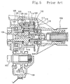
- Japanese Patent 2652715 discloses a four wheel drive with a center differential unit having a planetary gear. The center differential unit will now be explained by referring to a schematic cross section of a center differential unit shown in Fig. 5 and a schematic diagram in Fig. 6.
- An
output shaft 101 is connected with arear drive shaft 102, which transmits power to a rear differential unit by way of a propeller shaft. Theoutput shaft 101 and therear drive shaft 102 are provided to rotate coaxially viabushings 103 andthrust bearings 104. Areduction gear 105 is supported by theoutput shaft 101 via thebushings 103 and rotates on theoutput shaft 101. Thereduction gear 105 and theoutput shaft 101 are supported on agearbox casing 100 byball bearings 106. A centerdifferential unit 110 is provided over theoutput shaft 101, therear drive shaft 102 and thereduction gear 105 coaxially therewith. Thereduction gear 105 meshes with areduction gear 108 provided on afront drive shaft 107. Here, thefront drive shaft 107 functions to transmit power to a front differential unit. - The center
differential unit 110 includes a largediameter sun gear 111 on theoutput shaft 101 of a transmission on the input side, a smalldiameter sun gear 112 on therear drive shaft 102 on the output side, asmall diameter pinion 113 meshed with the largediameter sun gear 111, and alarge diameter pinion 114 meshed with the smalldiameter sun gear 112. Thesmall diameter pinion 113 and thelarge diameter pinion 114 are provided on asingle pinion member 115. - Moreover, a supporting
plate 117 for acarrier 116 is attached to therear drive shaft 102 by way of a ball bearing 118. The supportingplate 117 and thereduction gear 105 are united as an integral body, and apinion shaft 119 extends over the supportingplate 117 and thereduction gear 105. Thepinion member 115 is supported by thepinion shaft 119 havingneedle bearings 120 therebetween. Both ends of thepinion member 115 are supported on thereduction gear 105 and the supportingplate 117 by athrust washer 122 interposed therebetween. Anoil supply hole 121 is perforated on the pinion shaft for supplying oil to theneedle bearings 120. For thepinion shaft 119, high-carbon steel or case-hardened steel which has been subjected to a thermal treatment for hardening the surface is used . - In the above-mentioned center
differential unit 110 containing a planetary gear of a compound type without a ring gear, the differential function is attained by using the largediameter sun gear 111 and the smalldiameter sun gear 112 with an appropriate number of teeth. A disproportional torque ratio on the rear wheels is provided by appropriately distributing the output torque of the transmission. This is achieved by appropriately setting the distance from the meshing point of the largediameter sun gear 111 and thesmall diameter pinion 113 to the center of the largediameter sun gear 111, and the distance from the meshing point of the smalldiameter sun gear 112 and thelarge diameter pinion 114 to the center of the smalldiameter sun gear 112. - Alternatively, it is possible to use helical gears for the large
diameter sun gear 111, smalldiameter sun gear 112,small diameter pinion 113 andlarge diameter pinion 114 so as to generate a thrust load. The thrust load causes friction between the edges of thethrust washer 122 and thepinion member 115. In addition, force resulting from a separation load and a tangential load is applied to thesmall diameter pinion 113,large diameter pinion 114 and a contacting face between thepinion member 115 and the pinion shaft 119 (needle bearings 120). Accordingly, frictional force is generated on theneedle bearings 120. Thus, a differential control mechanism is provided. - In Japanese Patent 2652715, a radial load is applied to the
pinion member 115 depending upon an input torque. In order to eliminate a seizure of thepinion shaft 119 with thepinion member 115, and the galling of these, theneedle bearings 120 are provided as bearings for thepinion member 115. Theneedle bearings 120 can be replaced by bushings. - The needle bearing 120 is durable against a large load, but has a small frictional resistance, since it is a rolling bearing. On the other hand, the bushings contact with the
pinion member 115 by sliding therebetween. Therefore, the bushing has a large frictional resistance, but a seizure will occur when lubricating oil is insufficiently supplied. Accordingly, it is difficult to take an appropriate countermeasure when large torque for reducing differential action is required based on a load when traveling for instance on a muddy road or a road with a bad surface condition. - Usually, metal materials are employed for the
pinion member 115 and thepinion shaft 119 in order to attain a sufficient strength. When large torque for reducing differential action is necessary, it is possible to increase friction between thepinion member 115 and thepinion shaft 119 by supporting the pinion member directly on thepinion shaft 119 without providing the needle bearing 120 or the bushing. In this case, however, it is impossible for thepinion shaft 119 and the pinion member to endure such a large stress, which causes seizure. Alternatively, if forced lubrication is carried out so as to prevent the seizure, the frictional resistance between thepinion shaft 119 and thepinion member 115 is decreased. - In order to obtain sufficient friction, it is effective to use a paper material, which is usually used as a friction material for a multi-plate clutch for an automatic transmission, by interposing the paper material between the
pinion shaft 119 and thepinion member 115. However, the paper material is not suitable for practical use when lubricating oil containing an additive of a mineral material is used for the differential gear. This is because the durability of the paper friction material is largely decreased due to absorption of such oil. - In this way, it is difficult to obtain both sufficient friction and torque for reducing differential action.
- It is therefore a first object of the present invention to provide a center differential unit of a planetary gear type which provides torque for reducing differential action corresponding to an input torque in addition to maintaining a stable function of a planetary gear contained therein by obtaining a sufficient frictional force between a pinion shaft and a pinion member without interposing a bearing or a bushing therebetween and efficiently eliminating a seizure therebetween, comprising a carrier; a first sun gear for receiving an output from a transmission and positioned interiorly of the carrier; a second sun gear provided on an output side with respect to the first sun gear and positioned interiorly of the carrier; a first pinion meshing with the first sun gear; a second pinion meshing with the second sun gear; a pinion member carrying the first pinion and the second pinion therearound, the pinion member having a shaft-receiving hole; and a pinion shaft having at least a surface of carbon/carbon composite, the pinion shaft supported by the carrier at one end on the output side and directly supporting the pinion member so as to rotate by being inserted into the shaft-receiving hole of the pinion member.
- The first object of the present invention can also be achieved by the center differential unit of the planetary gear type, wherein the pinion shaft is made entirely of carbon/carbon composite.
- A second object of the present invention is to provide the center differential unit which provides torque for reducing differential action with an improved reliability with efficiently maintaining a sufficient frictional force between the pinion shaft and the pinion member contained in the planetary gear, wherein force resulting from a separation load and a tangential load generated at a meshing point of the first sun gear and the first pinion and a meshing point of the second sun gear and the second pinion is applied to the pinion shaft.
A third object of the present invention is to provide the center differential unit which provides a larger quantity of torque for reducing the differential action, wherein the first sun gear, the second sun gear, the first pinion and the second pinion are helical gears, a thrust load generated at a meshing point of the first sun gear and the first pinion, and a thrust load generated at a meshing point of the second sun gear and the second pinion cause frictional force between the second sun gear and the carrier. - A fourth object of the present invention is to provide a center differential unit of a planetary type which provides torque for reducing differential action corresponding to an input torque with maintaining a stable function of a planetary gear contained therein and a sufficient frictional force between a pinion shaft and a pinion member without further providing a bearing or a bushing as a separate member therebetween and by efficiently eliminating a seizure therebetween, comprising a carrier; a first sun gear for receiving a output from a transmission and positioned interiorly of the carrier; a second sun gear provided on an output side with respect to the first sun gear and positioned interiorly of the carrier; a first pinion meshing with the first sun gear; a second pinion meshing with the second sun gear; a pinion member carrying the first pinion and the second pinion therearound, the pinion member having a shaft-receiving hole; a bearing made of carbon/carbon composite provided in the shaft-receiving hole; and a pinion shaft made of a steel material, the pinion shaft supported by the carrier at one end on the output side and directly supporting the pinion member so as to rotate by being inserted into the shaft-receiving hole of the pinion member.
- A fifth object of the present invention is to provide the center differential unit which provides torque for reducing differential action with an improved reliability with efficiently maintaining a sufficient frictional force between the pinion shaft and the pinion member contained in the planetary gear, wherein force resulting from a separation load and a tangential load generated at a meshing point of the first sun gear and the first pinion and a meshing point of the second sun gear and the second pinion is applied to the pinion shaft.
- A sixth object of the present invention is to provide the center differential unit which provides larger quantity of torque for reducing differential action wherein the first sun gear, the second sun gear, the first pinion and the second pinion are helical gears, a thrust load generated at a meshing point of the first sun gear and the first pinion, and a thrust load generated at a meshing point of the second sun gear and the second pinion cause frictional force between the second sun gear and the carrier.
- A seventh object of the present invention is to provide the center differential unit containing a planetary gear having a smaller member, wherein the carbon/carbon composite has a bending strength in the range of 200 MPa to 1200 MPa, a compressive strength in the range of 100 MPa to 800 MPa, and an interlaminar shear strength in the range of 20 MPa to 600 MPa.
- An eighth object of the present invention is to provide a planetary gear which functions in a stable manner and is light in weight and simple in structure by having a sufficient frictional force between a pinion shaft and a pinion member without providing a bearing or a bushing therebetween and efficiently eliminating a seizure therebetween, comprising a carrier; a sun gear provided interiorly of the carrier; a pinion meshing with the sun gear; a pinion member carrying the pinion therearound, the pinion member having a shaft-receiving hole; and a pinion shaft having at least a surface of carbon/carbon composite, the pinion shaft supported by the carrier and directly supporting the pinion member so as to rotate by being inserted into the shaft-receiving hole of the pinion member.
- The eighth object of the present invention can also be achieved by the planetary gear wherein the pinion shaft is made entirely of carbon/carbon composite.
- A ninth object of the present invention is to provides a planetary gear which is light in weight and simple in structure by maintaining a sufficient frictional force between a pinion shaft and a pinion member without further providing a bearing or a bushing as a separate member therebetween and efficiently eliminating a seizure therebetween, comprising a carrier; a sun gear provided interiorly of the carrier; a pinion meshing with the sun gear; a pinion member carrying the pinion therearound, the pinion member having a shaft-receiving hole; a bearing made of carbon/carbon composite provided in the shaft-receiving hole; and a pinion shaft made of a steel material, the pinion shaft supported by the carrier and directly supporting the pinion member so as to rotate by being inserted into the shaft-receiving hole of the pinion member.
- A tenth object of the present invention is to provide the planetary gear having a smaller member, wherein the carbon/carbon composite has a bending strength in the range of 200 MPa to 1200 MPa, a compressive strength in the range of 100 MPa to 800 MPa, and an interlaminar shear strength in the range of 20 MPa to 600 MPa.
- Specific embodiments of the present invention will now be described, by way of examply only, with reference to the accompanying drawings, wherein:
- Fig. 1 is a schematic diagram of a transmission for showing a first embodiment of a center differential unit containing a planetary gear of the present invention;
- Fig. 2 is a schematic cross section of a center differential unit;
- Fig. 3 is a schematic perspective view of a center differential unit;
- Fig. 4 is a schematic cross section of a transmission showing a second embodiment of a center differential unit containing a planetary gear of the present invention;
- Fig. 5 is a schematic cross section of a transmission showing a conventional center differential unit; and
- Fig. 6 is a schematic diagram of the center differential unit shown in Fig. 5.
-
- A first embodiment of a center differential unit containing a planetary gear of the present invention will be explained by referring to the figures.
- In the first embodiment, a manual transmission is used.
- Fig. 1 is a schematic diagram of the transmission; Fig. 2 is a schematic cross section of a center differential unit; and Fig. 3 is a perspective view of the center differential unit.
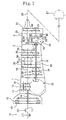
- Fig. 1 shows that a
transmission casing 1, atransfer casing 2 and anextension casing 3 are connected. Anengine 10 has a crank shaft 11 connected to a clutch 13 via aflywheel 12, and anintermediate shaft 14 extends from the clutch 13 to asub-transmission 15. - In the sub-transmission 15, a constant mesh type
counter gear mechanism 17, and asynchronizing mechanism 18 are provided between theintermediate shaft 14 and aninput shaft 16. By this structure, high and low speed switching is performed. Theinput shaft 16 extends into amanual transmission 30. Anoutput shaft 19 of themanual transmission 30 is provided in parallel with theinput shaft 16. Theinput shaft 16 is led into a centerdifferential unit 50 contained in theextension casing 3. Theoutput shaft 19 has a cylindrical shape, and afront drive shaft 20 contains theoutput shaft 19. The centerdifferential unit 50 is connected with a frontdifferential unit 21 provided in the sub-transmission 15 at a bottom part thereof by way of the centerdifferential unit 50. Torque is conveyed from the frontdifferential unit 21 to the front wheels. - A
rear drive shaft 23 is arranged in theextension casing 3 at the same height as theinput shaft 16 in themanual transmission 30. Arear output shaft 56 and therear drive shaft 23 are linked with each other by way of a pair of transfer gears 24, 25. Torque from therear drive shaft 23 is transmitted to apropeller shaft 26, a reardifferential unit 27 and the rear wheels. - The
manual transmission 30 is a constant mesh type, and afirst gear train 31, asecond gear train 32, athird gear train 33, afourth gear train 34, afifth gear train 35, and synchronizingmechanisms input shaft 16 and theoutput shaft 19 provided in parallel with each other. Further, areverse gear train 39 is positioned between thefirst gear train 31 and thesecond gear train 32. By selectively operating the synchronizingmechanisms reverse gear train 39 provides reverse drive. - As shown in Fig. 2, the
output shaft 19 extends into the centerdifferential unit 50. The centerdifferential unit 50 contains a centerdifferential input shaft 52, afront output shaft 54 and arear output shaft 56. The centerdifferential input shaft 52 has a cylindrical shape and one end of the centerdifferential input shaft 52 covers an outer surface of theoutput shaft 19 at an end by a spline connection through anintermediate member 51. Thefront output shaft 54 also has a cylindrical shape and is contained in the hollow portion of the centerdifferential input shaft 52. One end of thefront output shaft 54 is connected with thefront drive shaft 20 so as to cover an end outer surface of thefront drive shaft 20 by a spline connection having an intermediate member therebetween. Furthermore, thefront output shaft 54 contains therein a top portion of therear output shaft 56. The centerdifferential input shaft 52, thefront output shaft 54 and therear output shaft 56 coaxially rotate on each other. - A large
diameter sun gear 60 is provided at a base end of the centerdifferential input shaft 52 as an integral body. Asmall diameter pinion 61 is in mesh with the largediameter sun gear 60. On the other hand, a smalldiameter sun gear 63 is linked with therear output shaft 56 by a spline connection so as to be provided at an intermediate part of theoutput shaft 56. Alarge diameter pinion 64 is in mesh with the smalldiameter sun gear 63. - The
small diameter pinion 61 and thelarge diameter pinion 64 are formed integrally with ahollow pinion member 65 which has ahole 65a for receiving apinion shaft 67. Thus, the first and large diameter pinions 61 and 64 are supported on thepinion shaft 67 fixed to acarrier 66. - The center
differential input shaft 52 is inserted from the front to thecarrier 66, and therear output shaft 56 is inserted from the back so as to rotate. Thecarrier 66 contains the largediameter sun gear 60 and the smalldiameter sun gear 63 at an intermediate space as shown in Fig. 3. A planetary gear is structured by the provision of thepinion shaft 67 with thesmall diameter pinion 61 meshed with the largediameter sun gear 60 and thelarge diameter pinion 64 with the smalldiameter sun gear 63. - In the present invention, a carbon/carbon composite (hereinafter referred to as C/C composite) is used for the
pinion shaft 67. The C/C composite is a material prepared by impregnating carbon fibers, carbon textile or carbon filament/yarn with a thermosetting resin or a thermoplastic resin to obtain an impregnated material, followed by calcinating the impregnated material at a high temperature under a high pressure. Namely, the C/C composite is prepared by reinforcing a carbon matrix with carbon fibers. The thus obtained graphited C/C composite is used for thepinion shaft 67. - The conventional C/C composite has a bending strength of less than 200 MPa. In the present invention, it is preferable to use C/C composite having a bending strength in the range of 200 MPa to 1200 MPa, a compressive strength in the range of 100 MPa to 800 MPa, and an interlaminar shear strength in the range of 20 MPa to 600 MPa.
- When the C/C composite has the excellent mechanical strengths in the above range, it is possible to obtain a smaller member for the planetary gear, which is preferable for industrial use.
- The C/C composite is light and has an excellent thermal resistance, pressure resistance and abrasion resistance. Moreover, the C/C composite has a coefficient of friction which is appropriate for sliding contact with other members, and self-lubricating properties due to action of the carbon content as a lubricant.
- Therefore, it is possible to provide the
pinion shaft 67 which is light in weight and has satisfactory friction contact with thepinion member 65 when in sliding contact therewith. Furthermore, it is possible to eliminate or minimize seizure or undesired abrasion of thepinion shaft 67 with thepinion member 65 by use of the pinion shaft made of the C/C composite even when other lubrication cannot be sufficiently performed. The C/C composite is a porous material, thereby having excellent permeability and retention when lubricating oil is added to the C/C composite. - The
small diameter pinion 61 and thelarge diameter pinion 64 are spaced from each other on thepinion shaft 67 and are arranged at an internal part of thecarrier 66. Thecarrier 66 has ahub 70 on the internal surface. Thehub 70 extends from a gap between the largediameter sun gear 60 and the smalldiameter sun gear 63 to the inside of the centerdifferential input shaft 52 and is linked with the outer surface of thefront output shaft 54 by the spline connection. By this configuration, power transmitted to thecarrier 66 via thepinion shaft 67 is transmitted to thehub 70, thefront output shaft 54 and thefront drive shaft 20. On the other hand, power transmitted to therear output shaft 56 by way of the smalldiameter sun gear 63 is transmitted to therear drive shaft 23 via transfer gears 24 and 25. - At the back side of the
carrier 66, a cylindricalclutch hub 75 is supported by therear output shaft 56 via a thrust bearing so as to rotate around therear output shaft 56. Aclutch drum 76 is fixed on therear output shaft 56 and faces theclutch hub 75. Adrive plate 77, a drivenplate 78, and acone disc spring 79 are provided between theclutch hub 75 and theclutch drum 76. Theclutch hub 75, theclutch drum 76, thedrive plate 77, the drivenplate 78, and thecone disc spring 79 constitute an initialtorque generating unit 80. The initialtorque generating unit 80 is for generating a predetermined quantity of torque for limiting differential action (herein after referred to as "differential limiting torque") based on torque between thecarrier 66 and therear output shaft 56, that is, differential rotation between the front and rear wheels. The initial torque can be determined by appropriately selecting the pressing force created by thecone disc spring 79. - The center
differential unit 50 can be controlled to appropriately distribute a reference torque, for instance to provide a suitable disproportional torque distribution by providing a larger torque for the rear wheels. This control is made by properly setting the distance from the meshing point of the largediameter sun gear 60 and thesmall diameter pinion 61 to the center of the largediameter sun gear 60, and the distance from the meshing point of the smalldiameter sun gear 63 and thelarge diameter pinion 64 to the center of the smalldiameter sun gear 63. - A
first friction washer 81, a second friction washer 82, and athird friction washer 83 are interposed respectively between the largediameter sun gear 60 and thehub 70, between thehub 70 and the smalldiameter sun gear 63 and between the smalldiameter sun gear 63 and thecarrier 66. A differential control mechanism of the centerdifferential unit 50 is obtained by the frictional force generated by thefriction washers pinion shaft 67 and thehole 65a of thepinion member 65 for receiving apinion shaft 67. - In this embodiment, it is preferable to use helical gears for the large
diameter sun gear 60,small diameter pinion 61, smalldiameter sun gear 63 andlarge pinion 64. The threads of the helical gears are so structured that thesmall diameter pinion 61 applies a thrust load to urge the largediameter sun gear 60 to the rear side, i.e., to the hub side, and that thelarge diameter pinion 64 applies a thrust load to urge the smalldiameter sun gear 63 to the front side, i.e., to the hub side when the vehicle goes forward. - In the case where the vehicle goes forward, the
first friction washer 81 and the second friction washer 82 are pressed to thehub 70 by the largediameter sun gear 60 and the smalldiameter sun gear 63 to generate frictional force. In the case where the vehicle goes back, the thrust load of the small diameter sun gear works in a reversed direction, so that thethird friction washer 83 is pressed to thecarrier 66 by the largediameter sun gear 63 to give frictional force. - Force results from a separation load and a tangential load on the meshing point of the large
diameter sun gear 60 and thesmall diameter pinion 61, and on the meshing point of the smalldiameter sun gear 63 and thelarge diameter pinion 64 can be applied to a supporting part between thepinion shaft 67 and thesmall diameter pinion 61/large diameter pinion 63. Namely, the force is applied to the part between thepinion member 65 and thepinion shaft 67, whereby friction is obtained therebetween. - The thus obtained frictional force between the
pinion member 65 and thepinion shaft 67 works as frictional torque in a reversed direction with respect to the rotation of thepinion member 65, namely, as torque for reducing the differential. Thus, the structure with the helical gears is effective to generate torque for restricting the differential depending upon the input force. - Depending upon the difference of the rotation number of the front wheels from that of the rear wheels, the rotating directions of the pinions are changed. In this case, the functioning manner of the differential limiting torque also varies. In operation, differential action brought about by the function of differential limiting torque is automatically modified, when the vehicle turns under the situation where the rotation number of the front wheels is larger than that of the rear wheels, when the front wheels slip, and when the rear wheels slip under the situation where the rotation number of the front wheels is less than that of the rear wheels.
- The function of the center
differential unit 50 will be explained in detail. - When the clutch 13 is disengaged and gears are engaged for running forward while stopping or traveling, the
synchronizing mechanism fifth gear trains 31 to 35 (Fig. 1). The selected gear train synchronizes with theinput shaft 16. In this state, by letting the clutch 13 in, power from theengine 10 is input to theinput shaft 16 of themanual transmission 30 via thesub-transmission 15. The power varied by the selected transmission gear train is transmitted to theoutput shaft 19. When the clutch 13 is disengaged and thereverse gear train 36 is engaged, power in a reversed direction is output to theoutput shaft 19. In this way, 5 gearing states for forward movement and one gearing stage for backward movement are selected. - Power transmitted to the
output shaft 19 is input into the largediameter sun gear 60 by way of the centerdifferential input shaft 52 in the centerdifferential unit 50. Output from the largediameter sun gear 60 is transmitted to thepinion member 65 via thesmall diameter pinion 61. - When the vehicle goes forward, the center
differential unit 50 distributes torque to the front and rear wheels depending on the conditions of the gears. The power transmitted from thecarrier 66 is transmitted to the front wheels by way of thehub 70, thefront output shaft 54, thefront drive shaft 20, and the frontdifferential unit 21. On the other hand, power transmitted via the largediameter sun gear 63 is transmitted to therear output shaft 56, the transfer gears 24 and 25, therear drive shaft 23, thepropeller shaft 26 and the reardifferential unit 27. - For torque transmission, initial torque is generated by the force of the
cone disc spring 79 pressing thedrive plate 77 and the drivenplate 78 in the initialtorque generating unit 80, which is designed to produce a predetermined initial torque. The initial torque is applied to a portion between thecarrier 66 and therear output shaft 56. - By the differential relation between the front and rear wheels, a thrust load is generated corresponding to the input torque. The thrust load obtained by the
small diameter pinion 61 urging the largediameter sun gear 60 backward and thelarge diameter pinion 64 urging the smalldiameter sun gear 63 forward. Then, frictional force is generated between the largediameter sun gear 60 and thehub 70, and between the smalldiameter sun gear 63 and thehub 70 by way of the first andsecond friction washers 81 and 82. - The force, which results from a separation load and a tangential load on the meshing point of the large
diameter sun gear 60 and thesmall diameter pinion 61, and on the meshing point of the smalldiameter sun gear 63 and thelarge diameter pinion 64, is applied to the portion between thepinion member 65 and thepinion shaft 67 depending on the input torque value, whereby friction is obtained therebetween. The friction works as frictional torque in a reversed direction against the differential rotation of thepinion member 65. In other words, the friction is obtained as differential limiting torque, whereby a performance of the vehicle to run on a rough road surface, and driving stability are obtained. - For going backward, a thrust load on the small
diameter sun gear 63 is obtained in a reversed direction by the differential rotation between the front and rear wheels, and the smalldiameter sun gear 63 presses thethird friction washer 83 to thecarrier 66, thereby giving frictional force. Furthermore, the force which results from a separation load and a tangential load on the meshing point of the largediameter sun gear 60 and thesmall diameter pinion 61, and on the meshing point of thesmall sun gear 63 and thelarge diameter pinion 64, is applied to the portion between thepinion member 65 and thepinion shaft 67. Accordingly, friction is obtained between thepinion member 65 and thepinion shaft 67. The friction works as frictional torque in a reversed direction against the rotation of thepinion member 65. In other words, the friction is obtained as the differential limiting torque, whereby an excellent performance of the vehicle to run on a rough road surface and driving stability are obtained. - Since the
pinion shaft 67 is made of C/C composite which has a sufficient coefficient of friction, it is possible to directly support thepinion member 65 around thepinion shaft 67. The pinion member is supported by directly bearing when thepinion shaft 67 is brought into contact with other members by sliding therewith. Therefore, it is possible to maintain a satisfactory frictional force between thepinion shaft 67 and thepinion member 65. - As a result, seizure between the
pinion shaft 67 and thepinion member 65 can be effectively prevented, and necessary differential limiting torque can be obtained. Namely, the ability of the vehicle to run a long distance or to run on a bad road, and the driving stability are obtained. - In addition to the above, the
pinion shaft 67 of the present invention has self-lubricating properties due to the C/C composite when in sliding contact with other members. Further, thepinion shaft 67 has excellent permeability and retention, and stable lubricating properties, when lubricating oil is added to the porous C/C composite. - Therefore, the planetary gear and the center differential unit containing the planetary gear have sufficient durability and can be used for a long period time in a stable condition since the seizure or undesired abrasion of the
pinion shaft 67 and thepinion member 56 is eliminated. Simultaneously, a sufficient friction between thepinion member 65 and thepinion shaft 68 is obtained. Furthermore, it is possible to use oil for a manual transmission as a lubricant, that is convenient for practical use. - The weight of the
pinion shaft 67 made of C/C composite is largely reduced in comparison with conventional pinion shafts made of metal materials. It is possible to support thepinion member 65 directly by thepinion shaft 67 without using a needle bearing or a bushing. Consequently, there are such advantages that the number of the members is reduced, the shape/structure of thepinion shaft 67 is simple without having a lubricating-oil supply hole, assembling work is easy, and the manufacturing cost is largely reduced. - It is also possible to prepare the
pinion shaft 67 with a cylindrical C/C composite containing a steel core material as an integral structure. - A second embodiment of the present invention will be explained by referring to Fig. 4. In Fig. 4, members corresponding to those in Fig. 2 are indicated by the same reference numerals, and the detailed explanations on these common members are omitted.
- The
pinion member 65 is formed as an integral body with thesmall diameter pinion 61 and thelarge diameter pinion 64. Thepinion member 65 has thehole 65a for receiving apinion shaft 69. Inside thehole 65a, acylindrical bearing 68 made of the C/C composite is provided on the inner face of the shaft-receivinghole 65a as an integral structure. Thepinion shaft 69 is made of a steel material and fixed to thecarrier 66 by inserting thepinion shaft 69 in thebearing 68 with both ends fixed to thecarrier 66. The bearing 68 used for the present invention is integral with thepinion member 65. Thepinion member 65 is directly supported by thepinion shaft 69 without having needle bearings or bearings of any other separate types therebetween. By using the C/C composite for thebearing 68, the weight of thepinion member 65 is decreased, and thebearing 68 and thepinion shaft 69 which slide on each other produce sufficient friction. Even when other lubrication cannot be sufficiently performed, it is possible to eliminate or minimize the seizure or undesired abrasion of thepinion shaft 69 with thepinion member 65. - The center
differential unit 50 distributes torque to the front and rear wheels depending on the conditions of the gears when the vehicle goes forward. The power transmitted from thecarrier 66 is transmitted to the front wheels by thehub 70, thefront output shaft 54, thefront drive shaft 20, and the frontdifferential unit 21. On the other hand, the power transmitted via thelarge sun gear 63 is transmitted to therear output shaft 56, the transfer gears 24 and 25, therear drive shaft 23, thepropeller shaft 26 and the reardifferential unit 27. - For torque transmission, initial torque is generated by the force of the
cone disc spring 79 pressing thedrive plate 77 and the drivenplate 78 in the initialtorque generating unit 80, which is designed to produce a predetermined initial torque. The initial torque is applied to the portion between thecarrier 66 and therear output shaft 56. - A thrust load is generated corresponding to the input torque by the differential relation between the front and rear wheels. The thrust load is obtained by the
small diameter pinion 61 urging the largediameter sun gear 60 backward and thelarge diameter pinion 64 urging the smalldiameter sun gear 63 forward. Then, frictional force is generated between the largediameter sun gear 60 and thehub 70, and between the smalldiameter sun gear 63 and thehub 70 by way of the first andsecond friction washers 81 and 82. - The force, which results from a separation load and a tangential load on the meshing point of the large
diameter sun gear 60 and thesmall diameter pinion 61, and on the meshing point of the smalldiameter sun gear 63 and thelarge diameter pinion 64, is applied to thesmall diameter pinion 61, thelarge diameter pinion 64 and thepinion shaft 69. Therefore, the frictional force generates at a portion between the bearing 68 and thepinion shaft 69. The friction works as differential limiting torque, whereby the performance of the vehicle to run on a bad road and the driving stability are obtained. - For going backward, a thrust load on the small
diameter sun gear 63 is obtained in a reversed direction by the differential rotation between the front and rear wheels, and the smalldiameter sun gear 63 presses thethird friction washer 83 to thecarrier 66, thereby giving frictional force. Furthermore, the force which results from a separation load and a tangential load on the meshing point of the largediameter sun gear 60 and thesmall diameter pinion 61, and on the meshing point of the smalldiameter sun gear 63 and thelarge diameter pinion 64, is applied to the portion between the bearing 68 and thepinion shaft 69. Accordingly, friction between the bearing 68 and thepinion shaft 69 works as frictional torque in a reversed direction against the rotation of thepinion member 65. In other words, the friction is obtained as the differential limiting torque, whereby the performance of the vehicle to run on a bad road, and driving stability are obtained. - Since the
pinion shaft 69 is made of a steel material and thebearing 68 which is integral with thepinion member 65 is made of C/C composite, thepinion shaft 69 is supported by thepinion member 65 with maintaining a sufficient frictional force therebetween. - As a result, seizure between the
pinion shaft 69 and thebearing 68 can be effectively prevented, and necessary differential limiting torque can be obtained. Namely, the ability of the vehicle to run on the rough road surface and driving stability are obtained. Moreover, it is possible to eliminate seizure or undesired abrasion of thepinion shaft 69 with thebearing 68 because of the stable lubricating properties. Therefore, durability of the members is obtained and hence the planetary gear and the centerdifferential unit 50 containing the same can be used in a stable condition for a long period of time. - As previously mentioned, the
pinion shaft 69 directly supports thepinion member 65 containing the bearing 68 without interposing a needle bearing therebetween. Therefore, the number of the structural members is decreased and thepinion shaft 69 has a simple structure without necessity to have a lubricating oil supply hole. Due to the simple structure, the assembling is simplified and a large manufacturing cost reduction can be attained. - The central transmission unit and the planetary gear according to the present invention are also applicable to an automatic transmission. Further, it is possible that the output from the second sun gear is transmitted to the front differential unit and the output from the carrier is transmitted to the rear differential unit. The planetary gear of the invention can be widely used for devices other than the center differential unit.
- As clearly understood from the above, the planetary gear of the present invention or the planetary gear contained in the center differential unit of the present invention has a pinion shaft made of C/C composite at least on the surface, or the pinion member which is integral with a bearing made of C/C composite for supporting a pinion shaft made of a steel material. According to this structure, it is possible to obtain a sufficient friction between the pinion shaft and the pinion member or the pinion shaft and the bearing provided on the pinion member while maintaining differential limiting torque. Simultaneously, it is possible for the planetary gear or the center differential unit to have stable properties by eliminating seizure of the pinion shaft with the pinion member.
- In the present invention, a needle bearing or bushing as a separate member is not necessary to support a pinion member on a pinion shaft. Therefore, it is possible to reduce the number of members to be used. The structure of the planetary gear is simplified, and the manufacturing cost is largely reduced.
- The present invention being thus described, it will be clearly understood that the same may be varied in many ways. Such variations are not to be regarded as a departure from the spirit and scope of the present invention, and all such modification as would be easily understood to one skilled in the art are intended to be included within the scope of the invention.
Claims (14)
- A center differential unit of the planetary gear type comprising:a carrier;a first sun gear for receiving an output from a transmission and positioned interiorly of said carrier;a second sun gear provided on an output side with respect to said first sun gear and positioned interiorly of said carrier;a first pinion meshing with said first sun gear;a second pinion meshing with said second sun gear;a pinion member carrying said first pinion and said second pinion therearound, said pinion member having a shaft-receiving hole; anda pinion shaft having at least a surface of carbon/carbon composite, said pinion shaft supported by said carrier at one end on the output side and directly supporting said pinion member so as to rotate by being inserted into said shaft-receiving hole.
- The center differential unit of the planetary gear type as claimed in claim 1, wherein said pinion shaft is made entirely of carbon/carbon composite.
- The center differential unit of the planetary gear type as claimed in claim 1 or claim 2, wherein
force resulting from a separation load and a tangential load generated at a meshing point of said first sun gear and said first pinion and a meshing point of said second sun gear and said second pinion is applied to said pinion shaft. - The center differential unit of the planetary gear type as claimed in any of claims 1 to 3, wherein
said first sun gear, said second sun gear, said first pinion and said second pinion are helical gears, a thrust load generated at a meshing point of said first sun gear and said first pinion, and a thrust load generated at a meshing point of said second sun gear and said second pinion cause frictional force between said second sun gear and said carrier. - The center differential unit of the planetary gear type as claimed in any of claims 1 to 4, wherein said carbon/carbon composite has a bending strength in the range of 200 MPa to 1200 MPa, a compressive strength in the range of 100 MPa to 800 MPa, and an interlaminar shear strength in the range of 20 MPa to 600 MPa.
- A center differential unit of the planetary gear type comprising:a carrier;a first sun gear for receiving an output from a transmission and positioned interiorly of said carrier;a second sun gear provided on an output side with respect to said first sun gear and positioned interiorly of said carrier;a first pinion meshing with said first sun gear;a second pinion meshing with said second sun gear;a pinion member carrying said first pinion and said second pinion therearound, said pinion member having a shaft-receiving hole;a bearing made of carbon/carbon composite provided in said shaft-receiving hole; anda pinion shaft made of a steel material, said pinion shaft supported by said carrier at one end on the output side and directly supporting said pinion member so as to rotate by being inserted into said shaft-receiving hole.
- The center differential unit of the planetary gear type as claimed in claim 6, wherein force resulting from a separation load and a tangential load generated at a meshing point of said first sun gear and said first pinion and a meshing point of said second sun gear and said second pinion is applied to said pinion shaft.
- The center differential unit of the planetary gear type as claimed in claim 6 or claim 7, wherein said first sun gear, said second sun gear, said first pinion and said second pinion are helical gears, a thrust load generated at a meshing point of said first sun gear and said first pinion, and a thrust load generated at a meshing point of said second sun gear and said second pinion cause frictional force between said second sun gear and said carrier.
- The center differential unit of the planetary gear type as claimed in any of claims 6 to 8, wherein said carbon/carbon composite has a bending strength in the range of 200 MPa to 1200 MPa, a compressive strength in the range of 100 MPa to 800 MPa, and an interlaminar shear strength in the range of 20 MPa to 600 MPa.
- A planetary gear comprising:a carrier;a sun gear provided interiorly of said carrier;a pinion meshing with said sun gear;a pinion member carrying said pinion therearound, said pinion member having a shaft-receiving hole; anda pinion shaft having at least a surface of carbon/carbon composite, said pinion shaft supported by said carrier and directly supporting said pinion member so as to rotate by being inserted into said shaft-receiving hole of said pinion member.
- The planetary gear as claimed in claim 10, wherein said pinion shaft is made entirely of carbon/carbon composite.
- The planetary gear as claimed in Claim 10 or Claim 11, wherein said carbon/carbon composite has a bending strength in the range of 200 MPa to 1200 MPa, a compressive strength in the range of 100 MPa to 800 MPa, and an interlaminar shear strength in the range of 20 MPa to 600 MPa.
- A planetary gear comprising:a carrier;a sun gear provided interiorly of said carrier;a pinion meshing with said sun gear;a pinion member carrying said pinion therearound, said pinion member having a shaft-receiving hole;a bearing made of carbon/carbon composite provided in said shaft-receiving hole; anda pinion shaft made of a steel material, said pinion shaft supported by said carrier and directly supporting said pinion member so as to rotate by being inserted into said shaft-receiving hole.
- The planetary gear as claimed in Claim 13, wherein said carbon/carbon composite has a bending strength in the range of 200 MPa to 1200 MPa, a compressive strength in the range of 100 MPa to 800 MPa, and an interlaminar shear strength in the range of 20 MPa to 600 MPa.
Applications Claiming Priority (2)
| Application Number | Priority Date | Filing Date | Title |
|---|---|---|---|
| JP2001128994 | 2001-04-26 | ||
| JP2001128994 | 2001-04-26 |
Publications (2)
| Publication Number | Publication Date |
|---|---|
| EP1255059A2 true EP1255059A2 (en) | 2002-11-06 |
| EP1255059A3 EP1255059A3 (en) | 2009-04-15 |
Family
ID=18977593
Family Applications (1)
| Application Number | Title | Priority Date | Filing Date |
|---|---|---|---|
| EP02252930A Withdrawn EP1255059A3 (en) | 2001-04-26 | 2002-04-25 | Center differential unit and planetary gear |
Country Status (2)
| Country | Link |
|---|---|
| US (1) | US6620074B2 (en) |
| EP (1) | EP1255059A3 (en) |
Families Citing this family (8)
| Publication number | Priority date | Publication date | Assignee | Title |
|---|---|---|---|---|
| JP4140267B2 (en) * | 2002-04-22 | 2008-08-27 | 株式会社ジェイテクト | Differential gear device for vehicle |
| CN101232960A (en) * | 2005-08-31 | 2008-07-30 | 爱信艾达株式会社 | Manufacturing method for an annular member and a pronged annular member |
| US20080090692A1 (en) * | 2006-10-17 | 2008-04-17 | Gates Luther H | Transfer case center differential |
| US20090223052A1 (en) * | 2008-03-04 | 2009-09-10 | Chaudhry Zaffir A | Gearbox gear and nacelle arrangement |
| US9347542B2 (en) * | 2008-09-30 | 2016-05-24 | American Axle & Manufacturing, Inc. | Parallel-axis helical differential assembly |
| UA95852U (en) * | 2014-07-10 | 2015-01-12 | Товариство З Обмеженою Відповідальністю "Корум Груп" | pole of Planetary gear |
| JP6891659B2 (en) * | 2017-06-21 | 2021-06-18 | 株式会社ジェイテクト | Differential device |
| JP6704887B2 (en) * | 2017-10-17 | 2020-06-03 | 株式会社神戸製鋼所 | Bearing condition detector |
Citations (4)
| Publication number | Priority date | Publication date | Assignee | Title |
|---|---|---|---|---|
| US4171626A (en) * | 1978-03-27 | 1979-10-23 | Celanese Corporation | Carbon fiber reinforced composite drive shaft |
| EP0386922A1 (en) * | 1989-02-28 | 1990-09-12 | Fuji Jukogyo Kabushiki Kaisha | Torque distribution control system for a four-wheel drive motor vehicle |
| JPH03135842A (en) * | 1989-10-20 | 1991-06-10 | Fuji Heavy Ind Ltd | Power distribution control device for four wheel drive vehicle |
| US5230952A (en) * | 1991-06-17 | 1993-07-27 | Coltec Industries Inc. | Sintered composite friction material comprising fluorocarbon resin |
Family Cites Families (5)
| Publication number | Priority date | Publication date | Assignee | Title |
|---|---|---|---|---|
| JPS60184456U (en) * | 1984-05-18 | 1985-12-06 | 三菱電機株式会社 | gear |
| JPS61165656A (en) * | 1985-01-18 | 1986-07-26 | Mitsubishi Electric Corp | Formation of immobilized enzyme membrane |
| JP2897311B2 (en) * | 1989-02-22 | 1999-05-31 | セイコーエプソン株式会社 | Small reducer |
| JP3175240B2 (en) * | 1990-11-14 | 2001-06-11 | セイコーエプソン株式会社 | Small reducer |
| US5679089A (en) * | 1995-09-14 | 1997-10-21 | The United States Of America As Represented By The Secretary Of The Navy | Bicoupled contrarotating epicyclic gears |
-
2002
- 2002-04-25 EP EP02252930A patent/EP1255059A3/en not_active Withdrawn
- 2002-04-26 US US10/132,291 patent/US6620074B2/en not_active Expired - Fee Related
Patent Citations (4)
| Publication number | Priority date | Publication date | Assignee | Title |
|---|---|---|---|---|
| US4171626A (en) * | 1978-03-27 | 1979-10-23 | Celanese Corporation | Carbon fiber reinforced composite drive shaft |
| EP0386922A1 (en) * | 1989-02-28 | 1990-09-12 | Fuji Jukogyo Kabushiki Kaisha | Torque distribution control system for a four-wheel drive motor vehicle |
| JPH03135842A (en) * | 1989-10-20 | 1991-06-10 | Fuji Heavy Ind Ltd | Power distribution control device for four wheel drive vehicle |
| US5230952A (en) * | 1991-06-17 | 1993-07-27 | Coltec Industries Inc. | Sintered composite friction material comprising fluorocarbon resin |
Also Published As
| Publication number | Publication date |
|---|---|
| US6620074B2 (en) | 2003-09-16 |
| US20020160875A1 (en) | 2002-10-31 |
| EP1255059A3 (en) | 2009-04-15 |
Similar Documents
| Publication | Publication Date | Title |
|---|---|---|
| US4416168A (en) | Transmission and sub-transmission with mutually contending helical gears | |
| CA1112482A (en) | Compact transmission for use in automobiles | |
| US6855086B2 (en) | Motor vehicle transmission with a toroidal variable-speed drive unit | |
| US6793603B2 (en) | Power transmission system with sub transmission mechanism | |
| US7025704B2 (en) | Planetary gear for automatic transmission | |
| JPH04228915A (en) | Vibration interrupter for bearing | |
| EP0541023A1 (en) | Gear change for a vehicle with recovery of the axial play due to differential thermal expansion | |
| US20110070990A1 (en) | Drive system | |
| US6620074B2 (en) | Center differential unit and planetary gear | |
| EP0848190B1 (en) | Manual transmission for four wheel drive vehicle | |
| US3350960A (en) | Power transmission system | |
| US3126752A (en) | Transmission | |
| EP0657667A1 (en) | Transmission with countershaft and epicyclic gear for motor vehicle | |
| AU703818B2 (en) | Thermal compensating bearing support structure for transmission case | |
| US6991580B2 (en) | Toroidal variable-speed drive unit | |
| GB2335010A (en) | Gear synchronizing unit | |
| EP0172286B1 (en) | Transmission for use in motor vehicle | |
| GB2160598A (en) | Self regulating transmission | |
| US5538482A (en) | Multiple-speed axle mechanism providing overdrive and direct drive | |
| US20030176254A1 (en) | Toroidal variable-speed drive unit with rollers | |
| US5029688A (en) | Lubrication device for a one-way clutch in an automatic transmission | |
| US5526709A (en) | Manual transmission for motor vehicles having planetary gear unit | |
| JP4832980B2 (en) | Lubrication structure of differential equipment | |
| JP2003014083A (en) | Center differential gear and planetary gear | |
| JPH03149441A (en) | Belt type continuously variable transmission |
Legal Events
| Date | Code | Title | Description |
|---|---|---|---|
| PUAI | Public reference made under article 153(3) epc to a published international application that has entered the european phase |
Free format text: ORIGINAL CODE: 0009012 |
|
| AK | Designated contracting states |
Kind code of ref document: A2 Designated state(s): AT BE CH CY DE DK ES FI FR GB GR IE IT LI LU MC NL PT SE TR |
|
| AX | Request for extension of the european patent |
Free format text: AL;LT;LV;MK;RO;SI |
|
| PUAL | Search report despatched |
Free format text: ORIGINAL CODE: 0009013 |
|
| AK | Designated contracting states |
Kind code of ref document: A3 Designated state(s): AT BE CH CY DE DK ES FI FR GB GR IE IT LI LU MC NL PT SE TR |
|
| AX | Request for extension of the european patent |
Extension state: AL LT LV MK RO SI |
|
| AKX | Designation fees paid | ||
| REG | Reference to a national code |
Ref country code: DE Ref legal event code: 8566 |
|
| STAA | Information on the status of an ep patent application or granted ep patent |
Free format text: STATUS: THE APPLICATION IS DEEMED TO BE WITHDRAWN |
|
| 18D | Application deemed to be withdrawn |
Effective date: 20091016 |