EP1253804A2 - Speaker detecting device - Google Patents
Speaker detecting device Download PDFInfo
- Publication number
- EP1253804A2 EP1253804A2 EP02009452A EP02009452A EP1253804A2 EP 1253804 A2 EP1253804 A2 EP 1253804A2 EP 02009452 A EP02009452 A EP 02009452A EP 02009452 A EP02009452 A EP 02009452A EP 1253804 A2 EP1253804 A2 EP 1253804A2
- Authority
- EP
- European Patent Office
- Prior art keywords
- speaker
- unit
- signal
- level
- frequency band
- Prior art date
- Legal status (The legal status is an assumption and is not a legal conclusion. Google has not performed a legal analysis and makes no representation as to the accuracy of the status listed.)
- Withdrawn
Links
Images




Classifications
-
- H—ELECTRICITY
- H04—ELECTRIC COMMUNICATION TECHNIQUE
- H04R—LOUDSPEAKERS, MICROPHONES, GRAMOPHONE PICK-UPS OR LIKE ACOUSTIC ELECTROMECHANICAL TRANSDUCERS; ELECTRIC HEARING AIDS; PUBLIC ADDRESS SYSTEMS
- H04R5/00—Stereophonic arrangements
- H04R5/04—Circuit arrangements, e.g. for selective connection of amplifier inputs/outputs to loudspeakers, for loudspeaker detection, or for adaptation of settings to personal preferences or hearing impairments
-
- H—ELECTRICITY
- H04—ELECTRIC COMMUNICATION TECHNIQUE
- H04R—LOUDSPEAKERS, MICROPHONES, GRAMOPHONE PICK-UPS OR LIKE ACOUSTIC ELECTROMECHANICAL TRANSDUCERS; ELECTRIC HEARING AIDS; PUBLIC ADDRESS SYSTEMS
- H04R2205/00—Details of stereophonic arrangements covered by H04R5/00 but not provided for in any of its subgroups
- H04R2205/024—Positioning of loudspeaker enclosures for spatial sound reproduction
-
- H—ELECTRICITY
- H04—ELECTRIC COMMUNICATION TECHNIQUE
- H04R—LOUDSPEAKERS, MICROPHONES, GRAMOPHONE PICK-UPS OR LIKE ACOUSTIC ELECTROMECHANICAL TRANSDUCERS; ELECTRIC HEARING AIDS; PUBLIC ADDRESS SYSTEMS
- H04R2420/00—Details of connection covered by H04R, not provided for in its groups
- H04R2420/05—Detection of connection of loudspeakers or headphones to amplifiers
-
- H—ELECTRICITY
- H04—ELECTRIC COMMUNICATION TECHNIQUE
- H04R—LOUDSPEAKERS, MICROPHONES, GRAMOPHONE PICK-UPS OR LIKE ACOUSTIC ELECTROMECHANICAL TRANSDUCERS; ELECTRIC HEARING AIDS; PUBLIC ADDRESS SYSTEMS
- H04R29/00—Monitoring arrangements; Testing arrangements
- H04R29/001—Monitoring arrangements; Testing arrangements for loudspeakers
-
- H—ELECTRICITY
- H04—ELECTRIC COMMUNICATION TECHNIQUE
- H04S—STEREOPHONIC SYSTEMS
- H04S7/00—Indicating arrangements; Control arrangements, e.g. balance control
- H04S7/30—Control circuits for electronic adaptation of the sound field
- H04S7/308—Electronic adaptation dependent on speaker or headphone connection
Definitions
- This invention relates to an audio system using a plurality of speakers to createahigh-quality sound field space, and more particularly to a technique for automatically detecting state of speaker connection to the audio system.
- a user connects a plurality of speakers to the audio system and then manually inputs the speaker system configuration to the audio system.
- the audio system As a method of automatically detecting the speaker system configuration, it is conceivable to detect impedance variation of the audio system viewed from the side of the amplifier in the audio system so that the audio system can automatically detect the presence or absence of the speaker. Namely, since the impedance of the audio system viewed from the amplifier side changes according to the presence or absence of the speaker connected, the presence or absence of the speaker can be detected by detecting the impedance variation in the case a predetermined test signal is output.
- the above-described method requires an exclusive hardware to detect the presence or absence of the speaker.
- a speaker detecting device including: an output terminal for outputting a signal to drive a speaker; a test signal supplying unit for supplying the test signal to the output terminal; a test sound detecting unit, installed in an acoustic space in which the speaker is installed, for detecting a test sound corresponding to the test signal; and a speaker existence judging unit for judging whether or not a speaker is connected to the output terminal by comparing a signal level of the test sound, detected by the test sound detecting unit when the test signal supplying unit supplies the test signal to the output terminal, with a predetermined threshold level.
- the test signal is supplied to the output terminal to which the speaker is to be connected. If a speaker is connected to the output terminal, the test sound is output via the speaker. If no speaker is connected to the output terminal, no test sound is output.
- the test sound detecting unit detects the test sound in the acoustic space and compares the signal level of the test sound with the predetermined threshold level, thereby to judge whether or not a speaker is connected to the output terminal.
- the speaker detecting device may further include: an environmental noise detecting unit for detecting environmental noise in the acoustic space; and an optimum frequency band determining unit for determining an optimum frequency band of the test signal by analyzing a level of the environmental noise in terms of spectrum.
- the speaker existence judging unit may compare the level of the signal in the optimum frequency band, out of the signals detected by the test sound detecting unit, with the predetermined threshold level.
- the optimum frequency band determining unit may determine the frequency band having a highest acoustic S/N ratio as the optimum frequency band. Thus, the accuracy in the speaker existence detection may be improved.
- the optimum frequency band determining unit may include a unit for storing a predetermined signal curve data; a unit for detecting the level of the environmental noise detected by the environmental noise detecting unit for each of multiple frequency bands to produce a noise curve data; and a unit for determining the frequency band having the highest acoustic S/N ratio as the optimum frequency band by comparing the curve data with the noise curve data.
- the speaker detecting device may further include a threshold level setting unit for setting a level between the signal curve data and the noise curve data in the optimum frequency band to the predetermined threshold level.
- a threshold level setting unit for setting a level between the signal curve data and the noise curve data in the optimum frequency band to the predetermined threshold level.
- an appropriate threshold value may be set based on the actual S/N ratio in the optimum frequency band.
- the speaker existence judging unit may judge the existence of the speaker based on the signal level in the optimum frequency band when the level of the environmental noise is larger than a predetermined reference level, and may judge the existence of the speaker based on the signal level of all frequency bands when the level of the environmental noise is smaller than the predetermined reference level.
- the test signal of the optimum frequency band is used to accurately judge the speaker existence.
- the test signal of all frequency bands is used to quickly detect the speaker existence.
- the test signal supplying unit may supply only a component of the test signal in the optimum frequency band to the output terminal.
- test sound detecting unit and the environmental noise detecting unit may be integrally configured as a single acoustic detecting unit. Thus, the configuration needed for the speaker detection may be simplified.
- a computer program executable by a computer having an output terminal for outputting a signal to drive a speaker, to control the computer to function as a speaker detecting device
- a test signal supplying unit for supplying the test signal to the output terminal
- a test sound detecting unit installed in an acoustic space in which the speaker is installed, for detecting a test sound corresponding to the test signal
- a speaker existence judging unit for judging whether or not a speaker is connected to the output terminal by comparing a signal level of the test sound, detected by the test sound detecting unit when the test signal supplying unit supplies the test signal to the output terminal, with a predetermined threshold level.
- the computer may function as the above-described speaker detecting device.
- FIG. 1 is a block diagram showing an audio system employing the speaker detecting device according the embodiment of the invention.
- the audio system 100 includes a sound source 1 such as a CD (Compact Disc) player or a DVD (Digital Video Disc or Digital Versatile Disc) player, a signal processing circuit 2 to which the sound source 1 supplies digital audio signals SFL, SFR, SC, SRL, SRR, SWF, SSBL and SSBR via the multi-channel signal transmission path, and a test signal generator 3.
- a sound source 1 such as a CD (Compact Disc) player or a DVD (Digital Video Disc or Digital Versatile Disc) player
- a signal processing circuit 2 to which the sound source 1 supplies digital audio signals SFL, SFR, SC, SRL, SRR, SWF, SSBL and SSBR via the multi-channel signal transmission path
- a test signal generator 3 to which the sound source 1 supplies digital audio signals SFL, SFR, SC, SRL, SRR, SWF, SSBL and SSBR via the multi-channel signal transmission path.
- the audio system 100 includes the multi-channel signal transmission paths, the respective channels are referred to as “1st-channel” to "8th-channel” in the order from the top to the bottom in FIG. 1, according to need.
- the subscripts of the reference number are omitted to refer to all of the multiple channels when the signals or components are expressed.
- the subscript is put to the reference number when a particular channel or component is referred to.
- the description "digital audio signals S” means the digital audio signals SFL to SSBR
- the description "digital audio signal SFL” means the digital audio signal of only the FL-channel.
- the audio system 100 includes D/A converters 4FL to 4SBR for converting the digital output signals DFL to DSBR of the respective channels processed by the signal processing by the signal processing circuit 2 into analog signals, and amplifiers 5FL to 5SBR for amplifying the respective analog audio signals output by the D/A converters 4FL to 4SBR.
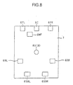
- the analog audio signals SPFL to SPSBR after the amplification by the amplifiers 5FL to 5SBR are supplied to the multi-channel speakers 6FL to 6SBR positioned in a listening room 7, shown in FIG. 8 as an example, to output sounds.
- the audio system 100 also includes a microphone 8 for collecting reproduced sounds at the listening position RV in the listening room 7, an amplifier 9 for amplifying a collected sound signal SM output from the microphone 8, and an A/D converter 10 for converting the output of the amplifier 9 into a digital collected sound data DM to supply it to the signal processing circuit 2.
- the audio system 100 activates full-band type speakers 6FL, 6FR, 6C, 6RL, 6RR having frequency characteristics capable of reproducing sound for substantially all audible frequency bands, a speaker 6WF having a frequency characteristic capable of reproducing only low-frequency sounds and surround speakers 6SBL and 6SBR positioned behind the listener, thereby creating sound field with presence around the listener at the listening position RV.
- the listener places the two-channel, left and right speakers (a front-left speaker and a front-right speaker) 6FL, 6FR and a center speaker 6C, in front of the listening position RV, according to the listener's taste. Also the listener places the two-channel, left and right speakers (a rear-left speaker and a rear-right speaker) 6RL, 6RR as well as two-channel, left and right surround speakers 6SBL, 6SBR behind the listening position RV, and further places the sub-woofer 6WF exclusively used for the reproduction of low-frequency sound at any position.
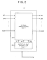
- the signal processing circuit 2 may have a digital signal processor (DSP), and roughly includes a signal processing unit 20 and a coefficient operating unit 30 as shown in FIG. 2.
- DSP digital signal processor
- the audio system shown in FIG. 1 operates in two modes.
- One is a sound source reproduction mode in which the audio signal output by the sound source shown in FIG. 1 is reproduced from a plurality of speakers .
- the other mode is a speaker detection mode, which is executed prior to the sound source reproduction mode. In the speaker detection mode, the existence, i.e., the presence or the absence of the speaker connected to the audio system 100 is automatically judged.
- the signal processing unit 20 receives the multi-channel digital audio signals from the sound source 1 reproducing sound from various sound sources such as CD, DVD or else, performs necessary processing and outputs the digital output signals DFL to DSBR.
- the signal processing unit 20 outputs the test signal from the test signal generator 3 via the transmission paths of the respective channels. Further, the signal processing unit 20 collects the test signal thus output by the microphone 8, and returns the test signal to the signal processing circuit 2.
- the signal processing circuit 2 processes the returned test signal to detect the existence of the speaker.
- FIG. 3 shows the configuration of the signal processing unit 20.
- the 1st to 8th channels FL to FBR include band-pass filters BPF1 to BPF8, and variable amplifiers ATG1 to ATG8 at the following stage of the band-pass filters BPF1 to BPF8.
- the signal processing unit 20 also includes the test signal generator 3 for outputting a test signal for the speaker detection, switches SW11 to SW81 and SW12 to SW82 provided for the respective channels, and a switch SWN for selectively supplying the output signal DN from the test signal generator 3 to the band-pass filters of the respective channels.
- the switches SWN and SW11 to SW81 are turned OFF and the switches SW12 to SW82 are turned ON.
- the signals SFL to SSB are supplied to the corresponding band-pass filters BPF1 to BPF8, respectively.
- Each of the band-pass filters is set to the through-state, and supplies the input signal to the variable amplifiers ATG1 to ATG8 for all frequency bands.
- the variable amplifiers ATG1 to ATG8 amplify the signals of the respective channels by appropriate amplitudes for the respective channels in accordance with the control signal SG supplied by the coefficient operation unit 30, and supplies the amplified signals to the D/A converters 4FL to 4SBR in FIG. 1 as the digital signals DFL to DSBR.
- the setting of the respective variable amplifiers ATG1 to ATG8 in the sound source reproduction mode is determined by an appropriate sound field correction process, the process is not directly related to the present invention, and hence the detailed description thereof will be omitted.
- the audio signals from the sound source 1 are reproduced by the channel unit.
- the switches SWN and SW11 to SW81 are turned ON and the switches SW12 to SW82 are turned OFF. Therefore, the test signal DN is supplied from the test signal generator 3 to the respective band-pass filters BPF1 to BPF8, and the speaker detection process described later in detail is executed.
- FIG. 4 shows a configuration of the coefficient operation unit 30.
- the coefficient operation unit 30 includes a spectrum analyzing unit 11, a level detecting unit 12, a system controller MPU, a band-pass filter 17, and a memory 15.
- the spectrum analyzing unit 11, the level detecting unit 12 and the band-pass filter 17 constitute DSP (Digital Sound Processor).
- the coefficient operation unit 30 In the speaker detection mode, the coefficient operation unit 30 generates the control signal SF1 for controlling the pass bands of the band-pass filters BPF1 to BPF8 in the signal processing unit 20, and also generates the control signal SG for controlling the amplitudes of the variable amplifiers ATG1 to ATG8 in the signal processing unit 20.
- the coefficient operation unit 30 supplies the control signals SF1 and SG to the signal processing unit 20.
- the spectrum analyzing unit 11 first receives the collected sound data DM obtained by collecting ambient sound by the microphone 8 in the state the speakers 6FL to 6SBR output no signal, and analyzes the spectrum of the collected sound data DM. Namely, the spectrum analyzing unit 11 divides the collected sound data DM into 9 frequency bands (e.g., 9 frequency bands from low-frequency band to high-frequency band), and detects the levels of the signals in the respective frequency bands to analyze the spectrum of the collected sound data DM of the environmental noise. Then, the spectrum analyzing unit 11 supplies the level data 21 indicating the levels of the respective frequency bands to the system controller MPU.
- 9 frequency bands e.g., 9 frequency bands from low-frequency band to high-frequency band
- the band-pass filter 17 extracts the component of a certain frequency band and supplies it to the level detecting unit 12.
- the level detecting unit 12 detects the signal level of the frequency band that the band-pass filter 17 passed, and supplies the detection level data 22 to the system controller MPU.
- the memory 15 stores threshold levels TH1 and TH2 described later, a signal curve determined in consideration of auditory characteristics of human being, and the speaker existence judgment resultfor the respective channels obtained by the speaker existence judgment process.
- the system controller MPU receives the level data 21 of the respective frequency bands from the spectrum analyzing unit 11.
- the system controller MPU also receives the level data 22 indicating the level of the frequency band extracted by the band-pass filter 17, compares it with the threshold levels TH1 to TH2 stored in the memory 15 to generate the control signals SF1 and SG, and supplies the control signals SF1 and SG to the signal processing unit 20.
- the speaker detect ion mode is executed. It is noted that the speaker detection mode described below is executed by the system controller MPU controlling the respective components in the signal processing unit 2.
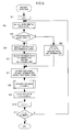
- the speaker detection process roughly includes a process to measure the environmental noise in the sound field such as a listening room and another process to determine the existence of the speakers thereafter. In the example shown in FIG. 5, these processes are executed for each channel.
- step S1 When the user instructs the start of the speaker detection process, first a variable x indicating the channel number is set to "1" (step S1). By this, out of the first to eighth speakers SPFL to SPSBR shown in FIG. 1, the first speaker SPFL is selected.
- the signal processing circuit 2 detects the environmental noise level of the sound field space such as the listening room 7 in which the audio system 100 is installed (step S2). Specifically, the microphone 8 collects the ambient sounds, and the amplifier 9 and the A/D converter 10 generate the digital collected sound data DM and supply it to the spectrum analyzing unit 11 and the level detecting unit 12. At this time, the BPF 17 in the coefficient operating unit 30 is set to the through state by which the input signal is output as it is. The level detecting unit 12 detects the environmental noise level from the collected sound data DM thus input, and supplies it to the system controller MPU as the level data 22. Since the BPF 17 is set to the through state, the level data 22 indicates the environmental noise of the sound field in all frequency bands.
- the system controller MPU judges whether or not the environmental noise level received as the level data 22 is smaller than a predetermined first threshold value TH1 (step S3).
- the first threshold value TH1 is a noise level value used as a reference to determine whether or not the acoustic S/N ratio necessary for executing the speaker detection process is maintained.
- the system controller MPU judges that the sound field is noisy and does not satisfy necessary S/N ratio, and executes the spectrum analysis of the environmental noise (step S4). Namely, the spectrum analyzing unit 11 divides the collected sound data DM into multiple frequency bands, detects sound level of each frequency bands, and supplies the level data 21 of each frequency band to the system controller MPU (step S4).
- the system controller MPU selects an optimum frequency band for the speaker detection based on the level data 21.
- the "optimum frequency band” is a frequency band silent enough to perform the speaker detection, and specifically a frequency band that has an acoustic S/N ratio larger than a predetermined reference value.
- the system controller MPU determines a second threshold value TH2 based on the S/N ratio of the selected frequency band, and stores the second threshold value TH2 in the memory 15. The method of determining the optimum frequency band and the second threshold value will be described later in detail.
- the system controller MPU generates the control signal SF1 to control the characteristics of the band-pass filters BPF1 to BPF8 such that the signal of the optimum frequency band is passed, and supplies the control signal SF1 to the respective band-pass filters BPF1 to BPF8.
- the system controller MPU also generates the control signal SF2 to set the pass-band of the band-pass filter 17 to the optimum frequency band and supplies the second control signal SF2 to the band-pass filter 17.
- the system controller MPU also generates the control signal SG to set the gain corresponding to the optimum frequency band to the respective variable amplifiers ATG1 to ATG8, and supplies them to the variable amplifiers ATG1 to ATG8 (step S5).
- the band-pass filters BPF1 to BPF8 are set to the characteristics to pass the signal in the optimum frequency band.
- the system controller MPU judges that the sound field satisfies the necessary acoustic S/N ratio for the speaker detection. Then, the system controller MPU determines the filter coefficients such that all of the band-pass filters BPF1 to BPF8 are set to the through state, and supplies the coefficients to the respective band-pass filters BPF1 to BPF8 as the control signal SF1. Further, the system controller MPU generates the control signal SG to set the amplification factors of the respective variable amplifies ATG1 to ATG8 to predetermined gains corresponding to the through state, and supplies the control signal SG to the variable amplifiers ATG1 to ATG8. The system controller MPU further sets the second threshold value TH2 to a predetermined value (step S6).
- the system controller MPU turns the switches SWN and SW11 ON and turns the other switches OFF.
- the test signal generator 3 generates the test signal DN, and the test signal DN is output by the speaker 6FL after passing through the band-pass filter BPF1 of the first channel and the variable amplifier ATG1.
- the microphone collects the test sound and supplies the collected sound data DM to the level detecting unit 12 via the band-pass filter 17 shown in FIG. 4.
- step S3 If the judgment in step S3 indicates that the environmental noise is smaller than the first threshold TH1 (i.e., the environmental noise is small), the band-pass filter 17 is set to the through state in step 56, and the level detecting unit 12 receives the level data 22 indicating the level of the test signal in all frequency bands. On the other hand, if the judgment in step S3 indicates that the environmental noise is larger than the first threshold TH1 (i.e., the environmental noise is large), the band-pass filter 17 is set to the optimum frequency band in step S4, and hence the level detecting unit 12 receives only the optimum frequency band component of the collected data DM, and supplies the level data 22 indicating that level to the system controller MPU.
- the system controller MPU compares the received level data 22 with the second threshold value TH2 determined in step S5 or S6 to judge the existence of the speaker (step S8).
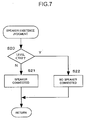
- the detail of the speaker existence judgment process is shown in FIG. 7.
- the level data 22 is compared with the second threshold value TH2 (step S20). If the level data 22 is larger than the second threshold value TH2, it is judged that a speaker is connected to the channel (step S21). On the contrary, if the level data 22 is smaller than the second threshold value TH2, it is judged that no speaker is connected to the channel (step S22). Then, the process returns to the main routine shown in FIG. 5.
- step S9 the system controller MPU stores the judgment result in the memory 15 (step S9). Then, the system controller MPU increments the variable x of the channel number by 1 (step S10), and then judges whether or not the variable x is larger than the number of the channels (step S11). If the variable x is not larger than the channel number, the process goes back to step S2 to execute the speaker judgment for the next channel (steps S2 to S10). On the other hand, if the variable x is larger than the channel number (step S11; Yes), the process ends because the speaker existence has already been judged for all channels.
- the speaker detection process described above if the environmental noise is small (more precisely, the S/N ratio is large), the test signal of all frequency bands is output, and the microphone 8 collects the test sound to judge the existence of the speaker.
- the environmental noise is large (more precisely, the S/N ratio is small)
- the speaker existence is judged by using the test signal of the optimum frequency band in which the S/N ratio is large enough. Therefore, since the speaker judgment is executed by using the test signal in the optimum frequency band in which the S/N ratio higher than a reference value is maintained, the speaker existence may be correctly detected automatically even in the sound field having relatively large environmental noise.
- the respective band-pass filters BPF1 to BPF8 are controlled such that the pass-bands of band-pass filters BPF1 to BPF8 in the signal processing unit 2 are set to the optimum frequency band.
- the pass-band of the band-pass filter corresponding to the channel (indicated by "x") subject to the speaker existence judgment may be controlled.
- the band-pass filter 17 in the coefficient operating unit 30 maybe set to the optimum frequency band, and the respective band-pass filters BPF1 to BPF8 may be set to the through state (i.e., passing all frequency bands). This is because, even if the band-pass filters BPF1 to BPF8 are set to the all frequency bands, by setting the band-pass filter 17 to the optimum frequency band, the level detecting unit 12 can detect the test signal level of only the optimum frequency band.
- the test signal of the frequency band subject to the level detection by the level detecting unit 12 is eventually output by the speaker, by setting the band-pass filters BPF1 to BPF8 on the test signal reproduction side to the optimum frequency bands, there is no need to output the test signal of the unnecessary frequency band (it may include large environmental noise because it is the frequency band other than the optimum frequency band) by the speaker. This prevents the test signal output by the speaker from giving uncomfortable noisy sound to persons in the sound field environment in which the speaker is installed.
- the output power of the speaker may be relatively reduced and the S/N ratio may be increased, thereby advantageously improving the detection accuracy.
- the speaker detection process shown in FIG. 5 judges the speaker existence by determining the optimum frequency band for each channel in step S4, the optimum frequency band determined for the first speaker may also be used for the other channels. It is inherently preferred that the optimum frequency band is determined for each channel individually. However, normally the determination of the optimum frequency band and the speaker existence judgment for each channel are executed in a relatively short time period, the optimum frequency band determined for the first channel may be appropriately used for other channels, unless the environmental noise state in the sound filed space suddenly varies. This can simplify and accelerate the speaker existence judgment process on the whole.
- the detection accuracy is low if the speaker existence is judges using the test signal in all frequency bands. Therefore, by outputting the test signal only in a particular frequency band and by detecting the level only in the frequency band, the speaker existence may be accurately detected with eliminating the influence of the environmental noise.
- the optimum frequency band is selected from some frequency bands, out of preset multiple frequency bands (9 frequency bands in this embodiment), that have the acoustic S/N ratio larger than a given reference value.
- a most theoretical method of selecting one frequency band from the candidate frequency bands having S/N ratio larger than the reference value is to select the frequency band having a largest S/N ratio.
- the optimum frequency band may be selected in consideration of parameters other than the S/N ratio.
- One characteristic point of the present invention is to consider the auditory characteristic of human being in the evaluation of the S/N ratio.
- the auditory characteristic of human being is not flat for all frequency ranges, and there are frequency bands in which the auditory sensibility is high and low. Therefore, even if the test signal of the same level is output from the speaker, the user may feel the test signal of the frequency range with high auditory sensibility noisy or uncomfortable, and may hardly hear the test signal of the frequency range with low auditory sensibility.
- a maximum allowable output level of the test signal is set for each frequency band in consideration of the auditory characteristic of human being.
- the maximum allowable output level is set to a highest level insofar as the user does not feel the test signal noisy or harsh, and the maximum allowable output level is defined in a form of a signal curve.
- An example of the signal curve is shown in FIG. 6.
- the signal curve 35 shows the maximum allowable output level of the test signal.
- the signal curve 35 may be predetermined in accordance with the auditory sensitivity curve of human being, or may be determined experimentally by actually outputting test signals of various frequency bands from the speaker and listening the output sound of the test signal. The data of the signal curve 35 thus determined is stored in the memory 17.
- the spectrum analyzing unit 11 detects the environmental noise levels of the sound field for the respective frequency bands, and supplies them to the system controller MPU as the level data 21. Based on the result of the noise level detection, the system controller MPU determines the noise curve 36 and stores it in the memory 15 in the same manner.
- the system controller MPU selects the frequency bands which S/N ratio is larger than the predetermined reference value (i.e., frequency bands for which the distance 38 between the signal curve 35 and the noise curve 36 is large) based on signal curve 35 and the noise curve 36 shown in FIG. 6, and determines one of those frequency bands, that has amaximum S/N ratio or that is determined in consideration of the other parameters, as the optimum frequency band.
- the system controller MPU determines the second threshold value TH2 in step S5 based on the signal curve 35 and the noise curve 36 of the optimum frequency band thus determined.
- the second threshold value TH2 may be the middle value of the signal curve 35 and the noise curve 36.
- the signal processing is achieved by the signal processing circuit.
- the signal processing may be designed as aprogram to be executed on a computer.
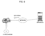
- the concept of this application is shown in FIG. 9.
- the program may be supplied in a form of storage medium such as CD-ROM or DVD, or supplied via the communication path through the network.
- the computer for executing this program may be a personal computer, to which an audio interface for multiple channels, multiple speakers and a microphone are connected as peripheral equipments.
- the measurement signal is generated by a sound source provided inside or outside of the computer, the measurement signal is output via the audio interface or speaker and the output sound is collected by the microphone.
- the automatic sound field correcting system shown in FIG. 1 may be achieved by a computer.
- the spectrum of the environmental noise is examined and the speaker existence detection is executed by using the frequency band with smaller noise, and hence the accuracy of speaker detection may be improved even in an environment with larger environmental noise.
- the output of the test signal of unnecessary frequency band (generally having lager noise) may be avoided, and a person in the sound field does not feel uncomfortable.
- the output power may be increased to improve the S/N ratio against the environmental noise in the sound field.
- the speaker detection can be performed more accurately.
Landscapes
- Physics & Mathematics (AREA)
- Engineering & Computer Science (AREA)
- Acoustics & Sound (AREA)
- Signal Processing (AREA)
- Stereophonic System (AREA)
- Stereophonic Arrangements (AREA)
- Circuit For Audible Band Transducer (AREA)
Abstract
Description
Claims (9)
- A speaker detecting device comprising:an output terminal (D) for outputting a signal to drive a speaker (6);a test signal supplying unit (3, 2) for supplying the test signal (DN) to the output terminal (D);a test sound detecting unit (8), installed in an acoustic space (7) in which the speaker is installed, for detecting a test sound corresponding to the test signal (DN); anda speaker existence judging unit (2) for judging whether or not a speaker (6) is connected to the output terminal (D) by comparing a signal level of the test sound, detected by the test sound detecting unit when the test signal supplying unit supplies the test signal to the output terminal, with a predetermined threshold level (TH2).
- A speaker detecting device according to claim 1, further comprising:an environmental noise detecting unit (8) for detecting environmental noise in the acoustic space (7); andan optimum frequency band determining unit (30) for determining an optimum frequency band of the test signal by analyzing a level of the environmental noise in terms of spectrum, wherein the speaker existence judging unit (2) compares the level of the signal in the optimum frequency band, out of the signals detected by the test sound detecting unit, with the predetermined threshold level (TH2).
- A speaker detecting device according to claim 2, wherein the optimum frequency band determining unit determines the frequency band having a highest acoustic S/N ratio as the optimum frequency band.
- A speaker detecting device according to claim 3, wherein the optimum frequency band determining unit comprises:a unit (15) for storing a predetermined signal curve data;a unit (11) for detecting the level of the environmental noise detected by the environmental noise detecting unit for each of multiple frequency bands to produce a noise curve data (36); anda unit (MPU) for determining the frequency band having the highest acoustic S/N ratio as the optimum frequency band by comparing the signal curve data with the noise curve data (36).
- A speaker detecting device according to claim 4, further comprising a threshold level setting unit (MPU) for setting a level between the signal curve data (35) and the noise curve data (36) in the optimum frequency band to the predetermined threshold level (TH2).
- A speaker detecting device according to any one off claims 2 to 5, wherein the speaker existence judging unit (30) judges the existence of the speaker based on the signal level in the optimum frequency band when the level of the environmental noise is larger than a predetermined reference level, and judges the existence of the speaker based on the signal level of all frequency bands when the level of the environmental noise is smaller than the predetermined reference level.
- A speaker detecting device according to any one of claims 3 to 5, wherein the test signal supplying unit (3, 2) supplies only a component of the test signal in the optimum frequency band to the output terminal.
- A speaker detecting device according to any one of claims 2 to 7, wherein the test sound detecting unit and the environmental noise detecting unit are integrally configured as a single acoustic detecting unit (8).
- A computer program executable by a computer, having an output terminal (D) for outputting a signal to drive a speaker (6), to control the computer to function as a speaker detecting device comprising:a test signal supplying unit (3) for supplying the test signal to the output terminal;a test sound detecting unit (8), installed in an acoustic space (7) in which the speaker is installed, for detecting a test sound corresponding to the test signal; anda speaker existence judging unit (2) for judging whether or not a speaker is connected to the output terminal by comparing a signal level of the test sound, detected by the test sound detecting unit when the test signal supplying unit supplies the test signal to the output terminal, with a predetermined threshold level (TH2).
Applications Claiming Priority (2)
| Application Number | Priority Date | Filing Date | Title |
|---|---|---|---|
| JP2001133573A JP4180807B2 (en) | 2001-04-27 | 2001-04-27 | Speaker detection device |
| JP2001133573 | 2001-04-27 |
Publications (2)
| Publication Number | Publication Date |
|---|---|
| EP1253804A2 true EP1253804A2 (en) | 2002-10-30 |
| EP1253804A3 EP1253804A3 (en) | 2009-01-07 |
Family
ID=18981408
Family Applications (1)
| Application Number | Title | Priority Date | Filing Date |
|---|---|---|---|
| EP02009452A Withdrawn EP1253804A3 (en) | 2001-04-27 | 2002-04-25 | Speaker detecting device |
Country Status (3)
| Country | Link |
|---|---|
| US (1) | US6813577B2 (en) |
| EP (1) | EP1253804A3 (en) |
| JP (1) | JP4180807B2 (en) |
Cited By (2)
| Publication number | Priority date | Publication date | Assignee | Title |
|---|---|---|---|---|
| EP1868414A1 (en) | 2006-06-14 | 2007-12-19 | Harman/Becker Automotive Systems GmbH | Method and system for checking an audio connection |
| DE102005027278B4 (en) * | 2005-06-14 | 2015-02-26 | Audi Ag | Apparatus for testing loudspeakers for operability |
Families Citing this family (10)
| Publication number | Priority date | Publication date | Assignee | Title |
|---|---|---|---|---|
| AU2003266040A1 (en) * | 2002-09-06 | 2004-03-29 | Measurement Microsystems A-Z Inc. | Method and apparatus for improving characteristics of acoustic and vibration transducers |
| JP4506604B2 (en) * | 2005-07-27 | 2010-07-21 | 株式会社デンソー | Hands-free device |
| US20080200094A1 (en) * | 2007-02-21 | 2008-08-21 | Sheng-Hung Hsu | Light show controller for an inflatable doll |
| CN101729957A (en) * | 2008-10-24 | 2010-06-09 | 深圳富泰宏精密工业有限公司 | Electronic device and method for eliminating sound volume mutation |
| JP5445574B2 (en) * | 2011-12-22 | 2014-03-19 | オンキヨー株式会社 | Channel divider, audio reproduction system including the same, and method for setting channel divider crossover frequency |
| US9338536B2 (en) * | 2013-05-07 | 2016-05-10 | Bose Corporation | Modular headrest-based audio system |
| EP3151587B1 (en) * | 2014-05-26 | 2022-08-31 | Yamaha Corporation | Connection confirmation system, connection confirmation program, connection confirmation method, and connection detection device |
| WO2018127942A1 (en) * | 2017-01-04 | 2018-07-12 | 三菱電機株式会社 | Speaker fault diagnosis device and fault diagnosis method |
| WO2020146728A1 (en) * | 2019-01-10 | 2020-07-16 | Parts Express International, Inc. | Measuring loudspeaker nonlinearity and asymmetry |
| CN114025296B (en) * | 2021-11-08 | 2025-01-24 | 林淡钦 | Intelligent test system for high-power speakers |
Family Cites Families (30)
| Publication number | Priority date | Publication date | Assignee | Title |
|---|---|---|---|---|
| JPS58129800U (en) * | 1982-02-26 | 1983-09-02 | 株式会社東芝 | Speaker inspection device |
| JPS6324800A (en) * | 1986-07-17 | 1988-02-02 | Mitsubishi Electric Corp | Acoustic device |
| JPS6348099A (en) * | 1986-08-16 | 1988-02-29 | Sony Corp | Inspection device |
| GB2199466A (en) * | 1986-11-08 | 1988-07-06 | G L Communications Limited | Monitoring loudspeakers |
| JPH03283800A (en) * | 1990-03-30 | 1991-12-13 | Mazda Motor Corp | On-vehicle acoustic equipment |
| JPH0480199U (en) * | 1990-11-26 | 1992-07-13 | ||
| JPH06100225B2 (en) | 1991-03-15 | 1994-12-12 | 光洋精工株式会社 | Superconducting bearing device |
| JPH06311579A (en) * | 1993-04-19 | 1994-11-04 | Clarion Co Ltd | Speaker connection deciding method for audio system |
| JPH077783A (en) * | 1993-06-14 | 1995-01-10 | Casio Comput Co Ltd | Alarm sound generator |
| US5361305A (en) * | 1993-11-12 | 1994-11-01 | Delco Electronics Corporation | Automated system and method for automotive audio test |
| US5748763A (en) * | 1993-11-18 | 1998-05-05 | Digimarc Corporation | Image steganography system featuring perceptually adaptive and globally scalable signal embedding |
| US5792072A (en) * | 1994-06-06 | 1998-08-11 | University Of Washington | System and method for measuring acoustic reflectance |
| US5920840A (en) * | 1995-02-28 | 1999-07-06 | Motorola, Inc. | Communication system and method using a speaker dependent time-scaling technique |
| EP0880779A1 (en) | 1995-06-20 | 1998-12-02 | André Rickli | Digital processing device for audio signal |
| US6570991B1 (en) * | 1996-12-18 | 2003-05-27 | Interval Research Corporation | Multi-feature speech/music discrimination system |
| JPH10199126A (en) | 1997-01-10 | 1998-07-31 | Nippon Columbia Co Ltd | Optical disk device |
| JPH10208375A (en) | 1997-01-21 | 1998-08-07 | Sanyo Electric Co Ltd | Disk clamping mechanism for optical disk reproducing device |
| JPH10271598A (en) * | 1997-03-26 | 1998-10-09 | Matsushita Electric Ind Co Ltd | Speaker line short-circuit inspection device |
| JPH10326454A (en) | 1997-05-26 | 1998-12-08 | Aimesu:Kk | Recording disk driving device and control method therefor |
| JPH11215588A (en) * | 1998-01-23 | 1999-08-06 | Hitachi Ltd | Audio output system |
| JP2000050565A (en) | 1998-07-24 | 2000-02-18 | Tokyo Parts Ind Co Ltd | Spindle motor |
| JP2000048474A (en) | 1998-07-30 | 2000-02-18 | Sanyo Electric Co Ltd | Turntable device for disk player |
| AU2254200A (en) | 1998-10-07 | 2000-04-26 | Phillippe Borieux | Method and device for manually controlling the direction and speed for data reading with a control disc |
| JP2000148161A (en) * | 1998-11-13 | 2000-05-26 | Matsushita Electric Ind Co Ltd | Automatic sound quality volume control method and device |
| JP2001043664A (en) | 1999-08-02 | 2001-02-16 | Nippon Columbia Co Ltd | Optical disk device |
| JP2001052424A (en) | 1999-08-10 | 2001-02-23 | Nippon Columbia Co Ltd | Operating dial and optical disk device |
| US6427137B2 (en) * | 1999-08-31 | 2002-07-30 | Accenture Llp | System, method and article of manufacture for a voice analysis system that detects nervousness for preventing fraud |
| US6675125B2 (en) * | 1999-11-29 | 2004-01-06 | Syfx | Statistics generator system and method |
| US6219645B1 (en) * | 1999-12-02 | 2001-04-17 | Lucent Technologies, Inc. | Enhanced automatic speech recognition using multiple directional microphones |
| US20020154787A1 (en) * | 2001-02-20 | 2002-10-24 | Rice Richard F. | Acoustical to optical converter for providing pleasing visual displays |
-
2001
- 2001-04-27 JP JP2001133573A patent/JP4180807B2/en not_active Expired - Fee Related
-
2002
- 2002-04-25 US US10/131,464 patent/US6813577B2/en not_active Expired - Lifetime
- 2002-04-25 EP EP02009452A patent/EP1253804A3/en not_active Withdrawn
Cited By (3)
| Publication number | Priority date | Publication date | Assignee | Title |
|---|---|---|---|---|
| DE102005027278B4 (en) * | 2005-06-14 | 2015-02-26 | Audi Ag | Apparatus for testing loudspeakers for operability |
| EP1868414A1 (en) | 2006-06-14 | 2007-12-19 | Harman/Becker Automotive Systems GmbH | Method and system for checking an audio connection |
| US8718286B2 (en) | 2006-06-14 | 2014-05-06 | Harman Becker Automotive Systems Gmbh | Audio connection testing system |
Also Published As
| Publication number | Publication date |
|---|---|
| JP4180807B2 (en) | 2008-11-12 |
| JP2002330498A (en) | 2002-11-15 |
| US20020161543A1 (en) | 2002-10-31 |
| US6813577B2 (en) | 2004-11-02 |
| EP1253804A3 (en) | 2009-01-07 |
Similar Documents
| Publication | Publication Date | Title |
|---|---|---|
| US7054448B2 (en) | Automatic sound field correcting device | |
| JP4361354B2 (en) | Automatic sound field correction apparatus and computer program therefor | |
| EP1253805A2 (en) | Automatic sound field correcting device | |
| EP1126744B1 (en) | Automatic sound field correcting system | |
| EP1657962A2 (en) | Setting a speaker mode | |
| EP2494792A2 (en) | Speech enhancement method and system | |
| EP1126746A2 (en) | Automatic sound field correcting system and a sound field correcting method | |
| US6813577B2 (en) | Speaker detecting device | |
| EP1126743A2 (en) | Method of correcting sound field in an audio system | |
| US20120082330A1 (en) | Method for signal processing in a hearing aid and hearing aid | |
| EP1511358A2 (en) | Automatic sound field correction apparatus and computer program therefor | |
| JP4283645B2 (en) | Signal delay time measuring apparatus and computer program therefor | |
| US20090015594A1 (en) | Audio signal processing device and computer program for the same | |
| JP4184420B2 (en) | Characteristic measuring device and characteristic measuring program | |
| EP1534047A2 (en) | Sound characteristic measuring device and method, automatic sound field correcting device and method | |
| JP4791613B2 (en) | Audio adjustment device | |
| JP4435232B2 (en) | Audio system | |
| JP6115160B2 (en) | Audio equipment, control method and program for audio equipment | |
| JP6115161B2 (en) | Audio equipment, control method and program for audio equipment | |
| JP4241828B2 (en) | Test signal generator and sound reproduction system | |
| JP2002353757A (en) | Automatic sound volume controller |
Legal Events
| Date | Code | Title | Description |
|---|---|---|---|
| PUAI | Public reference made under article 153(3) epc to a published international application that has entered the european phase |
Free format text: ORIGINAL CODE: 0009012 |
|
| AK | Designated contracting states |
Kind code of ref document: A2 Designated state(s): AT BE CH CY DE DK ES FI FR GB GR IE IT LI LU MC NL PT SE TR |
|
| AX | Request for extension of the european patent |
Free format text: AL;LT;LV;MK;RO;SI |
|
| PUAL | Search report despatched |
Free format text: ORIGINAL CODE: 0009013 |
|
| AK | Designated contracting states |
Kind code of ref document: A3 Designated state(s): AT BE CH CY DE DK ES FI FR GB GR IE IT LI LU MC NL PT SE TR |
|
| AX | Request for extension of the european patent |
Extension state: AL LT LV MK RO SI |
|
| AKX | Designation fees paid | ||
| STAA | Information on the status of an ep patent application or granted ep patent |
Free format text: STATUS: THE APPLICATION IS DEEMED TO BE WITHDRAWN |
|
| 18D | Application deemed to be withdrawn |
Effective date: 20090708 |
|
| REG | Reference to a national code |
Ref country code: DE Ref legal event code: 8566 |