EP1253588A1 - Optical head device - Google Patents
Optical head device Download PDFInfo
- Publication number
- EP1253588A1 EP1253588A1 EP01902732A EP01902732A EP1253588A1 EP 1253588 A1 EP1253588 A1 EP 1253588A1 EP 01902732 A EP01902732 A EP 01902732A EP 01902732 A EP01902732 A EP 01902732A EP 1253588 A1 EP1253588 A1 EP 1253588A1
- Authority
- EP
- European Patent Office
- Prior art keywords
- optical head
- head device
- light
- recording medium
- reflected
- Prior art date
- Legal status (The legal status is an assumption and is not a legal conclusion. Google has not performed a legal analysis and makes no representation as to the accuracy of the status listed.)
- Withdrawn
Links
Images


Classifications
-
- G—PHYSICS
- G11—INFORMATION STORAGE
- G11B—INFORMATION STORAGE BASED ON RELATIVE MOVEMENT BETWEEN RECORD CARRIER AND TRANSDUCER
- G11B7/00—Recording or reproducing by optical means, e.g. recording using a thermal beam of optical radiation by modifying optical properties or the physical structure, reproducing using an optical beam at lower power by sensing optical properties; Record carriers therefor
- G11B7/12—Heads, e.g. forming of the optical beam spot or modulation of the optical beam
- G11B7/135—Means for guiding the beam from the source to the record carrier or from the record carrier to the detector
- G11B7/1395—Beam splitters or combiners
-
- G—PHYSICS
- G11—INFORMATION STORAGE
- G11B—INFORMATION STORAGE BASED ON RELATIVE MOVEMENT BETWEEN RECORD CARRIER AND TRANSDUCER
- G11B7/00—Recording or reproducing by optical means, e.g. recording using a thermal beam of optical radiation by modifying optical properties or the physical structure, reproducing using an optical beam at lower power by sensing optical properties; Record carriers therefor
- G11B7/12—Heads, e.g. forming of the optical beam spot or modulation of the optical beam
- G11B7/135—Means for guiding the beam from the source to the record carrier or from the record carrier to the detector
- G11B7/1356—Double or multiple prisms, i.e. having two or more prisms in cooperation
-
- G—PHYSICS
- G11—INFORMATION STORAGE
- G11B—INFORMATION STORAGE BASED ON RELATIVE MOVEMENT BETWEEN RECORD CARRIER AND TRANSDUCER
- G11B7/00—Recording or reproducing by optical means, e.g. recording using a thermal beam of optical radiation by modifying optical properties or the physical structure, reproducing using an optical beam at lower power by sensing optical properties; Record carriers therefor
- G11B7/08—Disposition or mounting of heads or light sources relatively to record carriers
- G11B7/09—Disposition or mounting of heads or light sources relatively to record carriers with provision for moving the light beam or focus plane for the purpose of maintaining alignment of the light beam relative to the record carrier during transducing operation, e.g. to compensate for surface irregularities of the latter or for track following
- G11B7/0901—Disposition or mounting of heads or light sources relatively to record carriers with provision for moving the light beam or focus plane for the purpose of maintaining alignment of the light beam relative to the record carrier during transducing operation, e.g. to compensate for surface irregularities of the latter or for track following for track following only
- G11B7/0904—Dithered tracking systems
-
- G—PHYSICS
- G11—INFORMATION STORAGE
- G11B—INFORMATION STORAGE BASED ON RELATIVE MOVEMENT BETWEEN RECORD CARRIER AND TRANSDUCER
- G11B7/00—Recording or reproducing by optical means, e.g. recording using a thermal beam of optical radiation by modifying optical properties or the physical structure, reproducing using an optical beam at lower power by sensing optical properties; Record carriers therefor
- G11B7/12—Heads, e.g. forming of the optical beam spot or modulation of the optical beam
- G11B7/123—Integrated head arrangements, e.g. with source and detectors mounted on the same substrate
-
- G—PHYSICS
- G11—INFORMATION STORAGE
- G11B—INFORMATION STORAGE BASED ON RELATIVE MOVEMENT BETWEEN RECORD CARRIER AND TRANSDUCER
- G11B7/00—Recording or reproducing by optical means, e.g. recording using a thermal beam of optical radiation by modifying optical properties or the physical structure, reproducing using an optical beam at lower power by sensing optical properties; Record carriers therefor
- G11B7/12—Heads, e.g. forming of the optical beam spot or modulation of the optical beam
- G11B7/13—Optical detectors therefor
- G11B7/131—Arrangement of detectors in a multiple array
-
- G—PHYSICS
- G11—INFORMATION STORAGE
- G11B—INFORMATION STORAGE BASED ON RELATIVE MOVEMENT BETWEEN RECORD CARRIER AND TRANSDUCER
- G11B7/00—Recording or reproducing by optical means, e.g. recording using a thermal beam of optical radiation by modifying optical properties or the physical structure, reproducing using an optical beam at lower power by sensing optical properties; Record carriers therefor
- G11B7/12—Heads, e.g. forming of the optical beam spot or modulation of the optical beam
- G11B7/135—Means for guiding the beam from the source to the record carrier or from the record carrier to the detector
- G11B7/1353—Diffractive elements, e.g. holograms or gratings
-
- G—PHYSICS
- G11—INFORMATION STORAGE
- G11B—INFORMATION STORAGE BASED ON RELATIVE MOVEMENT BETWEEN RECORD CARRIER AND TRANSDUCER
- G11B7/00—Recording or reproducing by optical means, e.g. recording using a thermal beam of optical radiation by modifying optical properties or the physical structure, reproducing using an optical beam at lower power by sensing optical properties; Record carriers therefor
- G11B7/12—Heads, e.g. forming of the optical beam spot or modulation of the optical beam
- G11B7/135—Means for guiding the beam from the source to the record carrier or from the record carrier to the detector
- G11B7/1359—Single prisms
-
- G—PHYSICS
- G11—INFORMATION STORAGE
- G11B—INFORMATION STORAGE BASED ON RELATIVE MOVEMENT BETWEEN RECORD CARRIER AND TRANSDUCER
- G11B7/00—Recording or reproducing by optical means, e.g. recording using a thermal beam of optical radiation by modifying optical properties or the physical structure, reproducing using an optical beam at lower power by sensing optical properties; Record carriers therefor
- G11B7/12—Heads, e.g. forming of the optical beam spot or modulation of the optical beam
- G11B7/135—Means for guiding the beam from the source to the record carrier or from the record carrier to the detector
- G11B7/1372—Lenses
- G11B7/1374—Objective lenses
-
- G—PHYSICS
- G11—INFORMATION STORAGE
- G11B—INFORMATION STORAGE BASED ON RELATIVE MOVEMENT BETWEEN RECORD CARRIER AND TRANSDUCER
- G11B7/00—Recording or reproducing by optical means, e.g. recording using a thermal beam of optical radiation by modifying optical properties or the physical structure, reproducing using an optical beam at lower power by sensing optical properties; Record carriers therefor
- G11B7/12—Heads, e.g. forming of the optical beam spot or modulation of the optical beam
- G11B7/135—Means for guiding the beam from the source to the record carrier or from the record carrier to the detector
- G11B7/1372—Lenses
- G11B7/1376—Collimator lenses
-
- G—PHYSICS
- G11—INFORMATION STORAGE
- G11B—INFORMATION STORAGE BASED ON RELATIVE MOVEMENT BETWEEN RECORD CARRIER AND TRANSDUCER
- G11B7/00—Recording or reproducing by optical means, e.g. recording using a thermal beam of optical radiation by modifying optical properties or the physical structure, reproducing using an optical beam at lower power by sensing optical properties; Record carriers therefor
- G11B7/08—Disposition or mounting of heads or light sources relatively to record carriers
- G11B7/09—Disposition or mounting of heads or light sources relatively to record carriers with provision for moving the light beam or focus plane for the purpose of maintaining alignment of the light beam relative to the record carrier during transducing operation, e.g. to compensate for surface irregularities of the latter or for track following
- G11B7/0901—Disposition or mounting of heads or light sources relatively to record carriers with provision for moving the light beam or focus plane for the purpose of maintaining alignment of the light beam relative to the record carrier during transducing operation, e.g. to compensate for surface irregularities of the latter or for track following for track following only
Definitions
- the present invention relates to an optical head device for recording or reproducing information with respect to an information recording medium by a magneto-optical method.
- an optical head device of this kind for example, an optical head device disclosed in JP 6 (1994)-168462 A, etc. is known.
- FIG. 7 is an arrangement view showing an optical system of an optical head device and an information recording medium in the prior art.
- a configuration of a conventional optical head device will be described.
- a semiconductor laser device 101 and a photodetector 102 for servo signals for detecting focus error signals and tracking error signals are provided inside a semiconductor laser unit 107.
- a polarizing beam splitter 111, a collimating lens 112 and an objective lens 113 are arranged sequentially from the side of the semiconductor laser device 101.
- the polarizing beam splitter 111 is fixed on the upper surface of the semiconductor laser unit 107. Furthermore, on the surface at the side of the semiconductor laser device 101 of the polarizing beam splitter 111, a grating 109 is formed.
- photodetectors 104 for information signals are provided in the location of the side (right side in FIG. 7) of the polarizing beam splitter 111, and on the side surface at the side of the photodetector 104 for information signals of the polarizing beam splitter 111, a Wollaston prism 116 is provided.
- Reflective light Light emitted from the semiconductor laser device 101 and reflected by the information recording medium 114 (hereinafter, referred to as "return light") passes through the objective lens 113 and the collimating lens 112 sequentially, and then enters the polarizing beam splitter 111.
- This polarizing beam splitter 111 splits a portion of the return light by reflecting it in the direction of the Wollaston prism 116.
- the return light entering the Wollaston prism 116 is divided into the p-polarized light component and the s-polarized light component in the Wollaston prism 116.
- the two-divided photodetector 104 for information signals is placed in a place where the information signal light, which was divided into two components, is converged, respectively. Based on the output of this photodetector 104 for information signals, information signals are detected.
- the return light passing though the polarizing beam splitter 111 is diffracted by the grating 109 and then enters the photodetector 102 for servo signals. Then, based on the output from the photodetector 102 for servo signals, focus error signals and tracking error signals are detected.
- the light emitted from the semiconductor laser device 101 and the return light are indicated by broken lines.
- the optical intensity of light emitted from a semiconductor laser device depends on the exit angle as shown by the curve T in FIG. 8A. Therefore, in the above-mentioned conventional optical head device, when the objective lens 113 shifts in radial directions of the information recording medium 114, the optical intensity of the light taken in by the objective lens 113 is reduced. Therefore, as shown by the curve U in FIG. 8B, the tracking error signals decrease, thus making the servo operation unstable.
- the optical head device includes a semiconductor laser device irradiating an information recording medium with a laser beam, and a reflecting means for reflecting the laser beam reflected by the information recording medium and returning; wherein the reflectance of the laser beam by the reflecting means increases as the irradiating position on the reflecting means deviates from the optical axis of the laser beam.
- the optical intensity of the laser beam emitted from the semiconductor laser device depends on the exit angle so that it is reduced as the irradiating position on the reflecting means deviates from the center of the optical axis.
- the optical head device since the optical head device has a reflection characteristic such that the reflectance of the laser beam by the reflecting means increases as the irradiating position on the reflecting means deviates from the optical axis of the laser beam, it is possible to correct the dependence of the optical intensity of the laser beam on the exit angle. Therefore, it is possible to suppress the decrease in tracking error signals when the objective lens shifts in radial directions of the information recording medium. As a result, since the dependence of the strength of the tracking error signals on the objective lens shifts is reduced when compared to the conventional optical head device, the optical head device having a stable servo operation can be obtained.
- a photodetector for receiving the laser beam reflected by the reflecting means further is provided.
- a polarizing light splitting means for splitting the laser beam reflected by the information recording medium and returning is used as the reflecting means.
- the polarizing light splitting means is a polarizing beam splitter.
- the reflectance of a p-polarized light component of the laser beam is minimum when an incident angle of the laser beam reflected by the information recording medium and returning with respect to the reflecting face of the polarizing light splitting means is 45 degrees.
- the optical head device using the p-polarized light component so as to detect tracking error signals it is possible to prevent the tracking error signals from decreasing when the objective lens shifts in radial directions of the information recording medium. Furthermore, in this case, it is preferable that the reflectance of an s-polarized light component of the laser beam is minimum when an incident angle of the laser beam reflected by the information recording medium and returning with respect to the reflecting face of the polarizing light splitting means is 45 degrees. With such a preferable example, in the optical head device using the s-polarized light component so as to detect tracking error signals, it is possible to prevent the tracking error signals from decreasing when the objective lens shifts in radial directions of the information recording medium.
- the optical head device further includes a diffraction means for splitting the laser beam emitted from the semiconductor laser device into a plurality of sub-beams including a preceding sub-beam and a subsequent sub-beam, and a means for detecting tracking error signals; wherein the reflected light from the information recording medium relating to the preceding sub-beam or the subsequent sub-beam is reflected by the reflecting means and the reflected light is used so as to detect the tracking error signals.
- a diffraction means for splitting the laser beam emitted from the semiconductor laser device into a plurality of sub-beams including a preceding sub-beam and a subsequent sub-beam
- a means for detecting tracking error signals wherein the reflected light from the information recording medium relating to the preceding sub-beam or the subsequent sub-beam is reflected by the reflecting means and the reflected light is used so as to detect the tracking error signals.
- the optical head device further includes a diffraction means for splitting the laser beam emitted from the semiconductor laser device into a plurality of sub-beams including a preceding sub-beam and a subsequent sub-beam, and a means for detecting information signals and tracking error signals; wherein the reflected light from the information recording medium relating to the preceding sub-beam or the subsequent sub-beam is reflected by the reflecting means; the reflected light is further split into two light fluxes: a p-polarized light component and an s-polarized light component; and the two light fluxes are detected in the same light receiving region so as to detect the information signals and the tracking error signals.
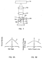
- FIG. 1 is an arrangement view showing a configuration of an optical head device in a first embodiment according to the present invention.
- a 3-beam-generating grating 2 for splitting laser beam emitted from the semiconductor laser device 1 into a plurality of sub-beams including a preceding sub-beam and a subsequent sub-beam
- a collimating lens 3 for splitting laser beam emitted from the semiconductor laser device 1 into a plurality of sub-beams including a preceding sub-beam and a subsequent sub-beam
- a collimating lens 3 for splitting laser beam emitted from the semiconductor laser device 1 into a plurality of sub-beams including a preceding sub-beam and a subsequent sub-beam
- a collimating lens 3 for splitting laser beam emitted from the semiconductor laser device 1 into a plurality of sub-beams including a preceding sub-beam and a subsequent sub-beam
- a collimating lens 3 for splitting laser beam emitted from the semiconductor laser device 1 into
- a beam splitter 8 In the optical path between the polarizing beam splitter 4 and a photodetector 13 for information signals, a beam splitter 8, a converging lens 11 and a Wollaston prism 12 are arranged sequentially from the side of the polarizing beam splitter 4. Furthermore, in an optical path between the polarizing beam splitter 4 and a photodetector 10 for servo signals, the beam splitter 8 and a converging lens 9 are arranged sequentially from the side of the polarizing beam splitter 4. Moreover, the polarizing beam splitter 4 is arranged so that the reflecting face thereof is inclined at 45 degrees with respect to an optical axis "a" (shown by a dashed line in FIG.
- the reflecting face of the polarizing beam splitter 4 has a reflection characteristic such that the reflectance is minimum when an incident angle of the return light L2 is 45 degrees and the reflectance increases as the incident angle of the return light L2 deviates from 45 degrees (that is, the return light L2 deviates from the optical axis "a") as shown in by the curve Y in FIG. 2B.
- the optical intensity of the laser beam L1 emitted from the semiconductor laser device 1 has the dependence on the exit angle as shown by the curve X in FIG. 2A and the optical intensity decreases as the laser beam L1 deviates from the center of the optical axis. If as it is, when the objective lens 6 shifts in radial directions of an information recording medium 7, the optical intensity of the laser beam L1 taken in by the objective lens 6 is reduced. As a result, the tracking error signals decrease, thus making the servo operation unstable.
- the reflecting face of the polarizing beam splitter 4 since the reflecting face of the polarizing beam splitter 4 has a reflection characteristic such that the reflectance is minimum when an incident angle of the return light L2 is 45 degrees whereas the reflectance increases as the incident angle of the return light L2 deviates from 45 degrees (FIG. 2B), it is possible to correct the dependence of the optical intensity of the laser beam L1 emitted from the semiconductor element 1 on the incident angle. Therefore, it is possible to suppress the tracking error signals from decreasing when the objective lens 6 shifts in radial directions of the information recording medium 7. As a result, as shown by the curve Z in FIG. 2C, the dependence of the intensity of the tracking error signals on the shift of the objective lens becomes smaller as compared with the conventional case (FIG. 8B). Therefore, the servo operation does not become unstable.
- the laser beam L1 emitted from the semiconductor laser device 1 is split into three beams, that is, a zero order diffracted light beam and ⁇ first order diffracted light beams when passing through the 3-beam-generating grating 2, and then enters the collimating lens 3.
- the laser beam L1 entering the collimating lens 3 is converted from divergent light fluxes into parallel light fluxes when passing through the collimating lens 3, and then it passes through the polarizing beam splitter 4.
- the laser beam L1 passing through the polarizing beam splitter 4 is reflected by the mirror 5 and then converged onto the information recording medium 7 by the objective lens 6.
- the light reflected by the information recording medium 7 travels on the above-mentioned optical path as a return light L2 in the opposite direction, and enters the polarizing beam splitter 4 again.
- a portion of the return light L2 entering the polarizing beam splitter 4 is reflected by polarizing beam splitter 4 (hereinafter, a portion of the return light L2 reflected by polarizing beam splitter 4 is referred to as "reflected split light") and enters a beam splitter 8.
- a portion of the reflected split light entering the beam splitter 8 passes through the beam splitter 8 as it is, subjected to the converging operation by the converging lines 11, and then enters the Wollaston prism 12.
- the light entering the Wollaston prism 12 is divided into the p-polarized light component and the s-polarized light component, and then received by the photodetector 13 for information signals.
- the information signal RF can be obtained.
- a portion of the rest of the split light entering the beam splitter 8 is reflected by the beam splitter 8, subjected to the converging operation by the converging lens 9 and then received by the photodetector 10 for servo signals. Then, focus error signals are detected by an astigmatic method and tracking error signals are detected by the 3-beam method.
- the tracking error signals are detected by using the reflected split light from the polarizing beam splitter 4.
- the reflecting face of the polarizing beam splitter 4 has a reflection characteristic such that the reflectance is minimum when an incident angle of the return light L2 is 45 degrees whereas the reflectance increases as the incident angle of the return light L2 deviates from 45 degrees. Therefore, the decrease of the tracking error signals can be suppressed when the objective lens 6 shifts in radial directions of the information recording medium 7, and thus the optical head device having a stable servo operation can be realized.
- the present invention is not necessarily limited to this method.
- the same effect can be obtained by using, for example, a phase difference method, or a push-pull method, further, a differential push-pull method, and the like.
- the optical head device having an afocal optical system provided with the collimating lens 3 and the objective lens 6 was described as an example.
- the optical head device is not necessarily limited to this configuration. The same effect can be obtained by using, for example, a focal optical system using only the objective lens 6.
- the information signal RF is detected by using the reflected split light from the polarizing beam splitter 4, even if the objective lens 6 shifts in radial directions of the information recording medium 7, the reduction in the information signals is not likely to occur. Consequently, the information signal with high quality can be obtained.
- the magneto-optical type head device in which the return light L2 is divided into the p-polarized light component and the s-polarized light component by using the Wollaston prism 12, thereby detecting information signals was described as an example.
- a beam splitter without polarization characteristic can be used instead of the polarizing beam splitter 4.
- FIG. 3 is an arrangement view showing a configuration of an optical head device in a second embodiment of the present invention
- FIG. 4 is a cross sectional view showing an optical unit shown in FIG. 3
- FIG. 5 is a plan view showing a light receiving substrate shown in FIG. 4
- FIG. 6 is a partial plan view showing a hologram optical element shown in FIGs. 3 and 4.
- FIG. 3 in this embodiment, all the component members necessary to constitute the optical head device excluding a collimating lens 3, a mirror 5 and an objective lens 6 are integrated into one unit as an optical unit 14.
- reference numeral 7 denotes an information recording medium.
- a semiconductor laser device 1 is placed in the concave portion provided on the light receiving substrate 23.
- photodetectors 26, 27 and 28 including a plurality of elements and photodetectors 29 and 30 are formed.
- the photodetector 26 includes six elements 26a, 26b, 26c, 26d, 26e and 26f.
- the photodetector 27 includes six elements 27a, 27b, 27c, 27d, 27e and 27f.
- the photodetector 28 includes two elements 28a and 28b.
- the light receiving substrate 23 is arranged inside a package 15 having a plurality of terminals 24.
- a hologram optical element 16 in which a 3-beam-generating grating 18 and a grating 19 are integrated, is placed as a cap.
- the grating 19 includes two grating regions 19a and 19b, each having a different lens effect.
- curves and the interval therebetween in FIG. 6 shows the outline of curves of the pitch of the grating and the interval therebetween.
- a composite microprism 17 on which a polarizing beam splitter 20, a reflection mirror 21 and a Wollaston prism 22 are integrated, is mounted.
- the polarizing beam splitter 20 is arranged in a state in which the reflecting face inclines by only 45 degrees with respect to an optical axis b (shown by a dashed line in FIG. 3) of the laser beam L1 (shown by broken line in FIGs. 3 and 4) emitted from the semiconductor laser device 1 and a return light L2 (shown by a broken line in FIGs. 3 and 4).
- the reflecting face of the polarizing beam splitter 20 has a reflection characteristic such that the reflectance of the reflecting face of the polarizing beam splitter 20 is minimum when an incident angle of the return light L2 is 45 degrees whereas the reflectance increases as the incident angle of the return light L2 deviates from 45 degrees (that is, the return light L2 deviates from the optical axis) as shown by the curve Y in FIG. 2B.
- This reflection characteristic also can be realized in a manner similar to the first Embodiment.
- the optical intensity of the laser beam L1 emitted from the semiconductor laser device 1 depends on the exit angle as shown by the curve X in FIG. 2A and the optical intensity is reduced as the laser beam L1 deviates from the center of the optical axis. If in this case, the objective lens 6 shifts in radial directions of the information recording medium 7, the optical intensity of the laser beam L1 taken in by the objective lens 6 is reduced. As a result, the tracking error signals decrease, thus making the servo operation unstable.
- the reflecting face of the polarizing beam splitter 20 has a reflection characteristic such that the reflectance is minimum when an incident angle of the return light L2 is 45 degrees whereas the reflectance increases as the incident angle of the return light L2 deviates from 45 degrees, it is possible to correct the dependence of the optical intensity of the laser beam light L1 emitted from the semiconductor laser device 1 on the exit angle. As a result, it is possible to suppress the decrease in the tracking error signals when the objective lens 6 shifts in radial directions of the optical recording medium. As a result, the dependence of the intensity of the tracking error signal on the shift of the objective lens becomes smaller as compared with the conventional case (FIG. 8B), as shown by the curve Z in the FIG. 2C, the servo signal does not become unstable.
- the laser beam L1 emitted from the semiconductor laser device 1 is split into three beams, that is, a zero order diffracted light beam and ⁇ first order diffracted light beams when passing through a 3-beam-generating grading 18, passes through a polarizing beam splitter 20, and then enters a collimating lens 3.
- the laser beam L1 entering the collimating lens 3 is first converted from divergent light fluxes into the parallel light fluxes when passing through the collimating lens 3, is reflected by the mirror 5 and converged onto the information recording medium 7 by the objective lens 6.
- the light reflected by the information recording medium 7 travels on the optical path mentioned above as a return light L2 in the opposite direction and enters the polarizing beam splitter 20 again.
- a portion of the return light L2 entering the polarizing beam splitter 20 passes through the polarizing beam splitter 20 (hereinafter, the return light L2, which passes through the polarizing beam splitter 20, is referred to as "passed-through split light") and is subjected to different diffracting and converging operations by the two grating regions 19a and 19b, respectively when entering the grating 19.
- the +first order diffracted light enters the elements 26d, 26e and 26f of the photodetector 26, and the -first order diffracted light enters the elements 27a, 27b and 27c of the photodetector 27.
- focus error signals FE can be detected by the calculation expressed by using the following Formula 1 by the D-SSD (Double Spot Size Detection) method.
- reference numeral 25 denotes a micro mirror for reflecting the light emitted from the semiconductor laser device 1 and leading it into the direction of the 3-beam-generating grating 18. Sub-beams diffracted by the grating 19 are omitted in the drawing for simplification.
- reflected split light a portion of the rest of the return light L2 entering the polarizing beam splitter 20 is reflected by the polarizing beam splitter 20 (hereinafter, the return light L2 reflected by the polarizing beam splitter 20 is referred to as "reflected split light"), then further reflected by the reflection mirror 21 and enters the Wollaston prism 22.
- the reflected split light entering the Wollaston prism 22 is divided into the p-polarized light component and the s-polarized light component, and the main beam is received by two elements 28a and 28b of the photodetector 28 by each polarized light component.
- an optical head device having a stable servo-operation can be realized. Furthermore, since almost all the components necessary to constitute the optical head device are integrated into one piece, a miniaturized and light weight optical head device can be realized. Furthermore, since information signal RF also can be detected by using the reflected split light from the polarizing beam splitter 20, even if the objective lens 6 shifts in radial directions of the information recording medium 7, the information signals are not like to be reduced. As a result, the high quality information signals can be obtained.
- the optical head device of the present invention has a reflection characteristic such that the reflectance of the reflecting means increases as laser beam deviates from the optical axis.
- a reflection characteristic such that the reflectance of the reflecting means increases as laser beam deviates from the optical axis.
Landscapes
- Physics & Mathematics (AREA)
- Optics & Photonics (AREA)
- Optical Head (AREA)
- Optical Recording Or Reproduction (AREA)
Abstract
Description
Claims (8)
- An optical head device, comprising:wherein the reflectance of the laser beam by the reflecting means increases as the irradiating position on the reflecting means deviates from the optical axis.a semiconductor laser device irradiating an information recording medium with laser beam, anda reflecting means for reflecting the laser beam reflected by the information recording medium and returning;
- The optical head device according to claim 1, further comprising a photodetector for receiving the laser beam reflected by the reflecting means.
- The optical head device according to claim 1, wherein a polarizing light splitting means for splitting the laser beam reflected by the information recording medium and returning is used as the reflecting means.
- The optical head device according to claim 3, wherein the polarizing light splitting means is a polarizing beam splitter.
- The optical head device according to claim 3, wherein the reflectance of a p-polarized light component of the laser beam is minimum when an incident angle of the laser beam reflected by the information recording medium and returning with respect to the reflecting face of the polarizing light splitting means is 45 degrees.
- The optical head device according to claim 3, wherein the reflectance of an s-polarized light component of the laser beam is minimum when an incident angle of the laser beam reflected by the information recording medium and returning with respect to the reflecting face of the polarizing light splitting means is 45 degrees.
- The optical head device according to claim 1, further comprising a diffraction means for splitting the laser beam emitted from the semiconductor laser device into a plurality of sub-beams including a preceding sub-beam and a subsequent sub-beam, and a means for detecting tracking error signals; wherein the reflected light from the information recording medium relating to the preceding sub-beam or the subsequent sub-beam is reflected by the reflecting means and the reflected light is used so as to detect the tracking error signals.
- The optical head device according to claim 1, further comprising a diffraction means for splitting the laser beam emitted from the semiconductor laser device into a plurality of sub-beams including a preceding sub-beam and a subsequent sub-beam, and a means for detecting information signals and tracking error signals; wherein the reflected light from the information recording medium relating to the preceding sub-beam or the subsequent sub-beam is reflected by the reflecting means; the reflected light is further split into two light fluxes, a p-polarized light component and an s-polarized light component; and the two light fluxes are detected in the same light receiving region so as to detect the information signals and the tracking error signals.
Applications Claiming Priority (3)
| Application Number | Priority Date | Filing Date | Title |
|---|---|---|---|
| JP2000027452 | 2000-02-04 | ||
| JP2000027452 | 2000-02-04 | ||
| PCT/JP2001/000725 WO2001057862A1 (en) | 2000-02-04 | 2001-02-01 | Optical head device |
Publications (2)
| Publication Number | Publication Date |
|---|---|
| EP1253588A1 true EP1253588A1 (en) | 2002-10-30 |
| EP1253588A4 EP1253588A4 (en) | 2005-03-23 |
Family
ID=18553021
Family Applications (1)
| Application Number | Title | Priority Date | Filing Date |
|---|---|---|---|
| EP01902732A Withdrawn EP1253588A4 (en) | 2000-02-04 | 2001-02-01 | OPTICAL HEAD |
Country Status (6)
| Country | Link |
|---|---|
| US (1) | US20020181384A1 (en) |
| EP (1) | EP1253588A4 (en) |
| KR (1) | KR100470469B1 (en) |
| CN (1) | CN1213417C (en) |
| TW (1) | TW492000B (en) |
| WO (1) | WO2001057862A1 (en) |
Cited By (1)
| Publication number | Priority date | Publication date | Assignee | Title |
|---|---|---|---|---|
| EP1962499A3 (en) * | 2007-02-20 | 2010-09-01 | Canon Kabushiki Kaisha | Lens apparatus |
Families Citing this family (4)
| Publication number | Priority date | Publication date | Assignee | Title |
|---|---|---|---|---|
| JP2007193894A (en) * | 2006-01-19 | 2007-08-02 | Sony Corp | Optical recording / reproducing apparatus, optical pickup, and tracking error signal detection method |
| JP5386553B2 (en) * | 2011-07-15 | 2014-01-15 | シャープ株式会社 | Optical pickup device |
| CN103076286B (en) * | 2011-10-26 | 2015-06-24 | 联发科技股份有限公司 | Photoacoustic microscope system and method for observing objects |
| KR102180125B1 (en) | 2019-03-11 | 2020-11-17 | 이상현 | Paper bag for packing |
Family Cites Families (11)
| Publication number | Priority date | Publication date | Assignee | Title |
|---|---|---|---|---|
| JPS58190906A (en) * | 1982-05-01 | 1983-11-08 | Sano Kiko Kk | Beam splitter |
| JPH0650568B2 (en) * | 1985-03-08 | 1994-06-29 | 松下電器産業株式会社 | Optical recording / reproducing device |
| JPH0677351B2 (en) * | 1986-11-15 | 1994-09-28 | ソニー株式会社 | Optical pickup device |
| GB2248989B (en) * | 1990-10-15 | 1995-05-24 | Applied Magnetics Corp | Focus sensing apparatus and method |
| JPH05314572A (en) * | 1992-05-13 | 1993-11-26 | Ricoh Co Ltd | Optical pickup device |
| JP3108552B2 (en) * | 1992-11-30 | 2000-11-13 | シャープ株式会社 | Optical head |
| EP0601862A1 (en) * | 1992-12-09 | 1994-06-15 | Omron Corporation | An optical device formed of multiple film layers |
| US5663940A (en) * | 1993-11-19 | 1997-09-02 | Sony Corporation | Optical pickup apparatus including hologram element |
| JP3601219B2 (en) * | 1996-11-13 | 2004-12-15 | 松下電器産業株式会社 | Parallel prism for optical pickup |
| KR19990074812A (en) * | 1998-03-14 | 1999-10-05 | 윤종용 | Compatible optical pickup device |
| JP2000011403A (en) * | 1998-06-29 | 2000-01-14 | Sony Corp | Optical information recording / reproducing apparatus and optical information recording / reproducing method |
-
2001
- 2001-01-31 TW TW090101877A patent/TW492000B/en not_active IP Right Cessation
- 2001-02-01 WO PCT/JP2001/000725 patent/WO2001057862A1/en not_active Ceased
- 2001-02-01 US US10/130,775 patent/US20020181384A1/en not_active Abandoned
- 2001-02-01 CN CNB018043666A patent/CN1213417C/en not_active Expired - Fee Related
- 2001-02-01 EP EP01902732A patent/EP1253588A4/en not_active Withdrawn
- 2001-02-01 KR KR10-2002-7001920A patent/KR100470469B1/en not_active Expired - Fee Related
Cited By (2)
| Publication number | Priority date | Publication date | Assignee | Title |
|---|---|---|---|---|
| EP1962499A3 (en) * | 2007-02-20 | 2010-09-01 | Canon Kabushiki Kaisha | Lens apparatus |
| US7852732B2 (en) | 2007-02-20 | 2010-12-14 | Canon Kabushiki Kaisha | Lens apparatus |
Also Published As
| Publication number | Publication date |
|---|---|
| WO2001057862A1 (en) | 2001-08-09 |
| CN1397069A (en) | 2003-02-12 |
| US20020181384A1 (en) | 2002-12-05 |
| KR20020081201A (en) | 2002-10-26 |
| CN1213417C (en) | 2005-08-03 |
| TW492000B (en) | 2002-06-21 |
| KR100470469B1 (en) | 2005-02-05 |
| EP1253588A4 (en) | 2005-03-23 |
Similar Documents
| Publication | Publication Date | Title |
|---|---|---|
| EP0991062A1 (en) | Optical pickup device and optical disk recording and/or reproducing device | |
| KR100483129B1 (en) | An optical head and an optical disk apparatus | |
| US5726962A (en) | Compact optical pickup device with beam splitter | |
| JP3083834B2 (en) | Optical pickup device | |
| KR100424837B1 (en) | Optical pickup apparatus | |
| JPH08171748A (en) | Optical pickup device | |
| EP1253588A1 (en) | Optical head device | |
| KR100286865B1 (en) | Optical head unit | |
| JPH07326083A (en) | Optical information reproducing device | |
| JPH09138967A (en) | Optical pickup device | |
| JP3489816B2 (en) | Optical pickup device | |
| KR100430364B1 (en) | Compatible Optical Pickups | |
| KR100464419B1 (en) | Compatible optical pickup for recording and/or reproducing | |
| JP2869318B2 (en) | Optical pickup device | |
| JP3213650B2 (en) | Optical pickup | |
| EP1037206A2 (en) | Optical pickup | |
| JP2007272980A (en) | Optical pickup device | |
| JP2993273B2 (en) | Magneto-optical head device | |
| JPWO2001057862A1 (en) | Optical Head Device | |
| JP4742159B2 (en) | Optical information reproduction method | |
| JP4123217B2 (en) | Optical pickup device, optical disk device, and focus error signal detection method | |
| JP3431679B2 (en) | Optical pickup device | |
| JP3558963B2 (en) | Optical pickup device | |
| JP2005310298A (en) | Optical pickup and optical information processing apparatus | |
| KR19990057682A (en) | Compatible Optical Pickup Device |
Legal Events
| Date | Code | Title | Description |
|---|---|---|---|
| PUAI | Public reference made under article 153(3) epc to a published international application that has entered the european phase |
Free format text: ORIGINAL CODE: 0009012 |
|
| 17P | Request for examination filed |
Effective date: 20020611 |
|
| AK | Designated contracting states |
Kind code of ref document: A1 Designated state(s): AT BE CH CY DE DK ES FI FR GB GR IE IT LI LU MC NL PT SE TR |
|
| AX | Request for extension of the european patent |
Free format text: AL;LT;LV;MK;RO;SI |
|
| RBV | Designated contracting states (corrected) |
Designated state(s): DE FR GB |
|
| A4 | Supplementary search report drawn up and despatched |
Effective date: 20050203 |
|
| 17Q | First examination report despatched |
Effective date: 20070323 |
|
| RAP1 | Party data changed (applicant data changed or rights of an application transferred) |
Owner name: PANASONIC CORPORATION |
|
| STAA | Information on the status of an ep patent application or granted ep patent |
Free format text: STATUS: THE APPLICATION IS DEEMED TO BE WITHDRAWN |
|
| 18D | Application deemed to be withdrawn |
Effective date: 20090901 |