EP1253582A2 - Load/unload operation control method and storage apparatus - Google Patents
Load/unload operation control method and storage apparatus Download PDFInfo
- Publication number
- EP1253582A2 EP1253582A2 EP01308223A EP01308223A EP1253582A2 EP 1253582 A2 EP1253582 A2 EP 1253582A2 EP 01308223 A EP01308223 A EP 01308223A EP 01308223 A EP01308223 A EP 01308223A EP 1253582 A2 EP1253582 A2 EP 1253582A2
- Authority
- EP
- European Patent Office
- Prior art keywords
- load
- driving current
- unload
- head
- storage apparatus
- Prior art date
- Legal status (The legal status is an assumption and is not a legal conclusion. Google has not performed a legal analysis and makes no representation as to the accuracy of the status listed.)
- Withdrawn
Links
Images







Classifications
-
- G—PHYSICS
- G11—INFORMATION STORAGE
- G11B—INFORMATION STORAGE BASED ON RELATIVE MOVEMENT BETWEEN RECORD CARRIER AND TRANSDUCER
- G11B21/00—Head arrangements not specific to the method of recording or reproducing
- G11B21/02—Driving or moving of heads
- G11B21/12—Raising and lowering; Back-spacing or forward-spacing along track; Returning to starting position otherwise than during transducing operation
-
- G—PHYSICS
- G11—INFORMATION STORAGE
- G11B—INFORMATION STORAGE BASED ON RELATIVE MOVEMENT BETWEEN RECORD CARRIER AND TRANSDUCER
- G11B5/00—Recording by magnetisation or demagnetisation of a record carrier; Reproducing by magnetic means; Record carriers therefor
- G11B5/48—Disposition or mounting of heads or head supports relative to record carriers ; arrangements of heads, e.g. for scanning the record carrier to increase the relative speed
- G11B5/54—Disposition or mounting of heads or head supports relative to record carriers ; arrangements of heads, e.g. for scanning the record carrier to increase the relative speed with provision for moving the head into or out of its operative position or across tracks
Definitions
- the present invention generally relates to load and/or unload operation control methods (hereinafter simply referred to as load/unload operation control methods) and storage apparatuses, and more particularly to a load/unload operation control method which controls a load operation which loads a recording and/or reproducing means such as a magnetic head with respect to a recording medium and/or controls an unload operation which unloads the recording and/or reproducing means from the recording medium, and to a storage apparatus which employs such a load/unload operation control method.
- load/unload operation control methods hereinafter simply referred to as load/unload operation control methods
- storage apparatuses and more particularly to a load/unload operation control method which controls a load operation which loads a recording and/or reproducing means such as a magnetic head with respect to a recording medium and/or controls an unload operation which unloads the recording and/or reproducing means from the recording medium, and to a storage apparatus which employs such a load/unload operation control method.
- a magnetic head is provided on a tip end of an arm, and a recording and/or reproducing hereinafter simply referred to as recording/reproducing) of information with respect to a desired position on a magnetic disk is carried out by moving the arm.
- the magnetic head In a state where no information recording/reproducing is carried out, the magnetic head is unloaded from a position above the recording surface of the magnetic disk to a parking area, so that the magnetic head will not hit the magnetic disk when an external disturbance such as shock and vibration is applied on the magnetic disk unit.
- an external disturbance such as shock and vibration
- the arm In order to prevent collision of the magnetic head and the magnetic disk during the load/unload operation, the arm is designed to move on a ramp member. More particularly, during the unload operation, the arm moves from a state where the magnetic head is positioned above the recording surface of the magnetic disk, moves up on a first sloping part of the ramp member, moves on a horizontal part of the ramp member, moves down on a second sloping part of the ramp member, and finally reaches the parking area. During the load operation, the arm moves in a sequence in reverse to that during the unload operation. For example, the arm is moved by a driving means such as a voice coil motor (VCM).
- VCM voice coil motor
- the arm in the parking area is held by a mechanical catch such as a magnetic catch in a state where the magnetic head is located in the parking area, so as to hold the magnetic head in the parking area.
- a current supplied to the VCM is sharply increased.
- the current supplied to the VCM is sharply increased.
- the current supplied to the VCM is sharply decreased when the arm reaches the parking area.
- Such information processing apparatuses include portable information processing apparatuses which use a battery as a power source, wherein a power save mode is provided to reduce unnecessary power consumption and the load/unload operation is frequently carried out in order to prevent collision of the magnetic head and the magnetic disk.
- Another and more specific object of the present invention is to provide a load/unload operation control method and storage apparatus, which can suppress generation of mechanical noise during a load/unload operation.
- Still another object of the present invention is to provide a load/unload operation control method for controlling a load/unload operation which loads/unloads a head which is provided on an arm with respect to a recording medium by a ramp load/unload mechanism, comprising a control step controlling a driving current which is supplied to a driving part which drives the arm so as to undergo a gradual change during at least one of a load operation and an unload operation.
- a load/unload operation control method of the present invention it is possible to suppress the generation of mechanical noise during the load/unload operation.
- a further object of the present invention is to provide a storage apparatus comprising a load/unload mechanism which carries out a ramp load/unload operation to load/unload a head which is provided on an arm with respect to a recording medium by a driving part which drives the arm, and a controller controlling a driving current which is supplied to the driving part so as to undergo a gradual change during at least one of a load operation and an unload operation.
- a load/unload mechanism which carries out a ramp load/unload operation to load/unload a head which is provided on an arm with respect to a recording medium by a driving part which drives the arm, and a controller controlling a driving current which is supplied to the driving part so as to undergo a gradual change during at least one of a load operation and an unload operation.
- the driving current may be changed in steps which do not exceed a predetermined amount of change.
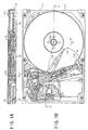
- FIGS. 1A and 1B are diagrams respectively showing an embodiment of a storage apparatus according to the present invention.
- FIG. 1B is a plan view of the storage apparatus
- FIG. 1A is a cross sectional view taken along a line X-X in FIG. 1B.
- the present invention is applied to a magnetic disk unit, that is, a hard disk drive (HDD).
- HDD hard disk drive
- This embodiment of the storage apparatus employs an embodiment of a load/unload operation control method according to the present invention.
- a HDD 10 generally includes a disk enclosure (DE) 11 and a printed circuit assembly (PCA) 12.
- DE disk enclosure
- PCA printed circuit assembly
- two magnetic disks 111 which are rotated in an arrow direction A by a spindle motor (SPM) 112, are accommodated within the disk enclosure 11.
- an arm 114 which is driven by a voice coil motor (VCM) 113, is provided within the disk enclosure 11 in a manner movable in an arrow direction B.
- VCM voice coil motor
- a magnetic head 115 is provided on a tip end of the arm 114.
- Two arms 114 and two magnetic heads 115 are provided since two magnetic disks 111 are provided in this embodiment.
- the magnetic head 115 can move in a radial direction of the magnetic disk 111 and record and/or reproduce information with respect to a desired track on the magnetic disk 111.
- the arm 114 is receded to a parking area other than above a recording surface of the magnetic disk 111, by a ramp mechanism 116 which will be described later.
- the ramp mechanism 116 is provided at an outer peripheral part of the magnetic disk 111.
- the ramp mechanism 116 may of course be provided at an inner peripheral part of the magnetic disk 111.
- the basic structure of the HDD 10 is not limited to that shown in FIG. 1, and various known structures provided with a ramp load/unload mechanism may be employed.
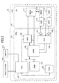
- FIG. 2 is a system block diagram showing a circuit structure of the HDD 10.
- those parts which are the same as those corresponding parts in FIG. 1 are designated by the same reference numerals, and a description thereof will be omitted.
- a head IC 117 which supplies a write signal to the magnetic head 115 and receives a read signal from the magnetic head 115, is provided within the disk enclosure 11.
- a hard disk controller (HDC) 121 which connects to a host system 100 such as a personal computer, a RAM 122, a flash ROM 123, a MPU 124, a read channel (RWC) 125, a servo controller (SVC) 126, and drivers 127 and 128 are provided within the PCA 12. Further, a load/unload (LUL) switch 130 connects to the HDC 121.
- a load/unload (LUL) switch 130 connects to the HDC 121.
- the write signal from the host system 100 is temporarily stored in the RAM 122 via the HDC 121, before being supplied to the magnetic head 115 via the RWC 125 and the head IC 117 under the control of the MPU 124.
- the write signal supplied to the magnetic head 115 is recorded on the magnetic disk 111.
- the read signal which is reproduced from the magnetic disk 111 by the magnetic head 115 is supplied to the RWC 125 via the head IC 117, and is temporarily stored in the RAM 122 via the HDC 121 under the control of the MPU 124, before being supplied to the host system 100 via the HDC 121.
- the MPU 124 executes a program stored in the ROM 123, so as to control the SPM 112 via the SVC 126 and the driver 128, and to control the VCM 113 via the SVC 126 and the driver 127.
- the VCM 113 drives the arm 114 so that the magnetic head 115 is loaded above the recording surface of the magnetic disk 111 from the ramp mechanism 116 during a load operation, and so that the magnetic head 115 is unloaded from above the recording surface of the magnetic disk 111 to the ramp mechanism 116 during the unload operation.
- a driving current which is supplied to the driving part that is, the VCM 113, will be referred to as a VCM current.
- the basic circuit structure of the HDD 10 is of course not limited to that shown in FIG. 2, and various known circuit structures provided with a ramp load/unload mechanism may be employed.
- a LUL switch 130 is provided to generate a switching signal which switches and sets the HDD 10 to a normal mode or a silent mode in which the generation of mechanical noise is suppressed.
- the LUL switch 130 may be formed by a physical switch which is provided in the HDD 10 and is connected to the HDC 121 or, formed by a software switch such as a program.
- a menu which enables selection of the normal mode or the silent mode is displayed at the host system 100, and mode information (switching signal) dependent on the selection made is supplied to the HDC 121 within the HDD 10 from the host system 100.
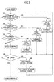
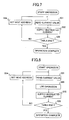
- FIG. 3 is a flow chart for explaining the load operation of this embodiment.
- the process shown in FIG. 3 is carried out by the MPU 124 shown in FIG. 2.
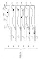
- FIG. 9 is a diagram for explaining positions of the magnetic head 115 during the load operation, and for the sake of convenience, the illustration of the arm 114 is omitted in FIG. 9. Further, the details of the ramp mechanism 116 is only shown in FIG. 9 (A). As shown in FIG.
- the ramp mechanism 116 includes a first'sloping part 116-1, a horizontal part 116-2, a second sloping part 116-3, a parking area 116-4, and a terminal wall 116-5.
- the present position of the magnetic head 115 is indicated by a symbol " ⁇ "
- the position of the magnetic head 115 before moving to the present position is indicated by a symbol " ⁇ ”.
- a step S1 supplies a VCM current for moving the arm 114 towards an outer peripheral direction of the magnetic disk 111 to the VCM 113, and decides whether or not a release operation which disengages the arm 114 from the magnetic catch has ended. If the decision result in the step S1 is YES, a step S2 decides whether or not a circuit calibration operation which supplies a VCM current for moving the arm 114 towards the outer peripheral direction of the magnetic disk 111 to the VCM 113 has ended.
- a step S3 supplies a VCM current for moving the arm 114 towards an inner peripheral direction of the magnetic disk 111 to the VCM 113, and decides whether or not a head feed operation with respect to the magnetic head 115 has ended. If the decision result in the step S3 is YES, a step S4 carries out a speed control operation which appropriately controls a moving speed of the arm 114 in the inner peripheral direction. This speed control operation is carried out based on a back-electromotive voltage of the VCM 113 which is fed back to the SVC 126 from the VCM 113 in FIG. 2.
- a step S5 decides whether or not a desired track on the magnetic disk 111 where the magnetic head 115 is to be loaded during the load operation is reached, that is, whether or not an on-track state is reached. If the decision result in the step S5 is NO, a step S6 supplies a VCM current for moving the arm 114 towards the outer peripheral direction of the magnetic disk 111 to the VCM 113, and returns the HDD 10 to a state where the unload operation has been completed. In addition, a step S7 calls a table of current values which sharply change, which is stored in the ROM 123, similarly to a case where a switching signal which sets the normal mode is received from the LUL switch 130, and the process returns to the step S1. On the other hand, the process ends if the decision result in the step S5 is YES.
- a step S11-1 carries out a table calling process
- a step S12-1 carries out a current instructing process
- the process returns to the step S1.
- a step S11-2 carries out a table calling process
- a step S12-2 carries out a current instructing process, and the process returns to the step S1.
- a step S11-3 carries out a table calling process, and a step S12-3 carries out a current instructing process, and the process returns to the step S1
- the table calling processes of the steps S11-1 through S11-3 are substantially the same, and only the table calling process of the step S11-1 will be described in the following description.
- the current instructing processes of the steps S12-1 through S12-3 are substantially the same, and only the current instructing process of the step S12-3 will be described in the following description.
- FIG. 4 is a flow chart for explaining a first embodiment of a table calling process 11-1 of the step S11-1.
- a step S21 decides whether or not the switching signal which sets the normal mode is received from the LUL switch 130. If the decision result in the step S21 is YES, a step S22 calls the table of current values which sharply change, which is stored in the ROM 123, and the table calling process 11-1 ends. On the other hand, if the decision result in the step S21 is NO, a step S23 calls a table of current values which gradually change, which is stored in the ROM 123, and the table calling process 11-1 ends.
- FIG. 5 is a flow chart for explaining a second embodiment of the table calling process 11-1 of the step S11-1.
- the table calling process 11-1 ends if the decision result in the step S21 is YES.
- a step S24 calls a lowpass filter (LPF) setting which is stored in the ROM 123, and the table calling process 11-1 ends.
- LPF lowpass filter
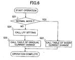
- FIG. 6 is a flow chart for explaining a third embodiment of the table calling process 11-1 of the step S11-1.
- those steps which are the same as those corresponding steps in FIGS. 4 and 5 are designated by the same reference numerals, and a description thereof will be omitted.
- the step S24 is carried out if the decision result in the step S21 is NO, and the table calling process 11-1 ends after carrying out the step S23.
- FIG. 7 is a flow chart for explaining a first embodiment of a current instructing process 11-2 of the step S11-2.
- a step S31 reads the current values from a starting read address of the table which is called by the table calling process 11-1 shown in FIG. 4, and a step S32 instructs a VCM current to be supplied to the VCM 113 based on the read current values.
- a step S33 decides whether or not the reading of the current values from the table has ended. If the decision result in the step S33 is NO, a step S34 sets a next read address of the table, and the process returns to the step S31. On the other hand, the current instructing process 11-2 ends if the decision result in the step S33 is YES.
- FIG. 8 is a flow chart for explaining a second embodiment of the current instructing process 11-2 of the step S11-2.
- the step S31 reads the current values from a starting read address of the table which is called by the table calling process 11-1 shown in FIG. 5 or 6, and a step S35 carries out a lowpass filter operation of the set lowpass filter with respect to the read current values. Accordingly, the step S32 instructs the VCM current to be supplied to the VCM 113 based on the operation result of the lowpass filter operation.
- the release operation is carried out as shown in FIG. 9 (B), and the circuit calibration operation is carried out as shown in FIG. 9 (C).
- the head feed operation is carried out as shown in FIG. 9 (D)
- the speed control operation is carried out as shown in FIG. 9 (E)
- the load operation is completed as shown in FIG. 9 (F).
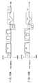
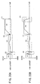
- FIGS. 10A and 10B are diagrams respectively showing the VCM current during the load operation for the normal mode and the silent mode.
- FIG. 10A shows the VCM current for the normal mode
- FIG. 10B shows the VCM current for the silent mode.
- the ordinate indicates the VCM current in arbitrary units
- an upward direction indicates the VCM current having a polarity for moving the arm 114 towards the outer peripheral direction of the magnetic disk 111
- a downward direction indicates the VCM current having a polarity for moving the arm 114 towards the inner peripheral direction of the magnetic disk 111.
- the abscissa indicates the time in arbitrary units.
- FIGS. 10A and 10B indicates the time in arbitrary units.
- waveform portions corresponding to the states shown in FIGS. 9 (A) through (F) are respectively denoted by the same reference characters (A) through (F).
- the change in the VCM current is sharp at the waveform portions (B) through (F) as shown in FIG. 10A.
- the silent mode the change in the VCM current is gradual at the waveform portions (B) through (F) as shown in FIG. 10B.
- the VCM current is controlled to change gradually during the load operation for at least the release operation which releases the arm 114 which is held in the unloaded state, the circuit calibration operation, the head feed operation which feeds the magnetic head 115 towards the magnetic disk 111, and the speed control operation which controls the speed when loading the magnetic head 115 on the desired track of the magnetic disk 111.
- the VCM current is controlled to change sharply during the load operation for at least the release operation which releases the arm 114 which is held in the unloaded state, the circuit calibration operation, the head feed operation which feeds the magnetic head 115 towards the magnetic disk 111, and the speed control operation which controls the speed when loading the magnetic head 115 on the desired track of the magnetic disk 111, so that the sharp change and the gradual change of the VCM current coexist.
- the VCM current supplied to the VCM 113 may be controlled to change' sharply for the head feed operation.
- FIG. 11 is a diagram for explaining a filter characteristic of the lowpass filter.
- the ordinate indicates the amplitude in arbitrary units
- the abscissa indicates the frequency in arbitrary units.
- FIGS. 12A and 12B are diagrams respectively showing a relationship of the VCM current and the mechanical noise during the normal mode.
- FIG. 12A shows the VCM current which changes sharply, and the ordinate indicates the amplitude of the VCM current in arbitrary units and the abscissa indicates the time in arbitrary units.
- FIG. 12B shows the mechanical noise which is generated when the VCM current shown in FIG. 12A is used, and the ordinate indicates the sound (noise) amplitude in arbitrary units and the abscissa indicates the time in arbitrary units.
- FIGS. 13A and 13B are diagrams respectively showing a relationship of the VCM current and the mechanical noise during the silent mode.
- FIG. 13A shows the VCM current which changes gradually, and the ordinate indicates the amplitude of the VCM current in arbitrary units and the abscissa indicates the time in arbitrary units.
- FIG. 13B shows the mechanical noise which is generated when the VCM current shown in FIG. 13A is used, and the ordinate indicates the sound (noise) amplitude in arbitrary units and the abscissa indicates the time in arbitrary units.
- FIGS. 14A and 14B are diagrams respectively showing a relationship of the VCM current and the mechanical noise during the silent mode, for a case where the VCM current is passed through the lowpass filter.
- FIG. 14A shows the VCM current which changes gradually, and the ordinate indicates the amplitude of the VCM current in arbitrary units and the abscissa indicates the time in arbitrary units.
- FIG. 14B shows the mechanical noise which is generated when the VCM current shown in FIG. 14A is used, and the ordinate indicates the sound (noise) amplitude in arbitrary units and the abscissa indicates the time in arbitrary units.
- FIGS. 15A and 15B are diagrams respectively showing a relationship of the VCM current and the mechanical noise during the silent mode, for a case where the upper limit of the steps of the VCM current is determined and the VCM is passed through the lowpass filter.
- FIG. 15A shows the VCM current which changes gradually, and the ordinate indicates the amplitude of the VCM current in arbitrary units and the abscissa indicates the time in arbitrary units.
- FIG. 15B shows the mechanical noise which is generated when the VCM current shown in FIG. 15A is used, and the ordinate indicates the sound (noise) amplitude in arbitrary units and the abscissa indicates the time in arbitrary units.
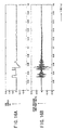
- FIGS. 16A and 16B are diagrams respectively showing the relationship of the VCM current and the mechanical noise during the loading in the normal mode.
- FIGS. 17A and 17B are diagrams respectively showing the relationship of the VCM current and the mechanical noise during the loading in the silent mode.
- FIGS. 16A and 17A show the change in the amplitude of the VCM current with respect to the time, in arbitrary units.
- FIGS. 16B and 17B show the change in the amplitude of the mechanical noise (sound pressure) with respect to the time, in arbitrary units, when the VCM currents shown in FIGS. 16A and 17A are used, respectively.
- the generation of the mechanical noise is suppressed and the mechanical noise can be substantially eliminated in the silent mode because the change in the VCM current is gradual.
- FIG. 18 is a flow chart for explaining the unload operation of this embodiment.
- the process shown in FIG. 18 is carried out by the MPU 124 shown in FIG. 2.
- those steps which are the same as those corresponding steps in FIGS. 6 and 8 are designated by the same reference numerals, and a description thereof will be omitted.
- FIG. 19 is a diagram for explaining positions of the magnetic head 115 during the unload operation, and for the sake of convenience, the illustration of the arm 114 is omitted in FIG. 19. Further, the details of the ramp mechanism 116 is only shown in FIG. 19 (A). As shown in FIG.
- the ramp mechanism 116 includes a first sloping part 116-1, a horizontal part 116-2, a second sloping part 116-3, a parking area 116-4, and a terminal wall 116-5.
- the present position of the magnetic head 115 is indicated by a symbol " ⁇ "
- the position of the magnetic head 115 before moving to the present position is indicated by a symbol " ⁇ ”.
- the magnetic head 115 In an initial state, the magnetic head 115 is located above an arbitrary track on the magnetic disk 111 as shown in FIG. 19 (A). When carrying out the unload operation, the magnetic head 115 is first caused to seek from the arbitrary track of the magnetic disk 111 to a specific track (cylinder) of the magnetic disk 111 as shown in FIG. 19 (B), so as to start the unload operation from this specific track.
- a step S41 supplies an appropriate VCM current to the VCM 113, so as to make the magnetic head 115 seek to the specific track of the magnetic disk 111, that is, carry out a seek operation.
- a step S42 decides whether or not the seek operation is completed, and the process returns to the step S41 if the decision result in the step S42 is NO. On the other hand, if the decision result in the step S42 is YES, a step S43 starts to count a speed control time.
- a step S44 carries out a speed control operation similar to that carried out by the step S4 shown in FIG.
- a step S45 decides whether or not a predetermined time has elapsed from a time when the counting of the speed control time is started, and the process returns to the step S44 if the decision result in the step S45 is NO. On the other hand, if the decision result in the step S45 is YES, the process advances to a step ST1, and the process ends after carrying out a step ST2.
- step ST1 is the same as the third embodiment of the table calling process shown in FIG. 6, but it is of course possible to employ the first or second embodiment of the table calling process shown in FIG. 4 or 5.
- step ST2 is the same as the second embodiment of the current instructing process shown in FIG. 8, but it is of course possible to employ the first embodiment of the current instructing process shown in FIG. 7 when first embodiment of the table calling process shown in FIG. 4 is employed for the step ST1.
- the seek operation to the specific track is carried out as shown in FIG. 19 (B), and the speed control operation is carried out as shown in FIG. 19 (C).
- the arm 114 hits the terminal wall 116-5 of the parking area 116-4 as shown in FIG. 19 (D)
- the VCM current is supplied so as to push the arm 114 against the terminal wall 116-5 as shown in FIG. 19 (E)
- the arm 114 is held by the magnetic catch as shown in FIG. 19 (F) so as to complete the unload operation.
- FIGS. 20A and 20B are diagrams respectively showing the VCM current during the unload operation for the normal mode and the silent mode.
- FIG. 20A shows the VCM current for the normal mode
- FIG. 20B shows the VCM current for the silent mode.
- the ordinate indicates the VCM current in arbitrary units
- an upward direction indicates the VCM current having a polarity for moving the arm 114 towards the outer peripheral direction of the magnetic disk 111
- a downward direction indicates the VCM current having a polarity for moving the arm 114 towards the inner peripheral direction of the magnetic disk 111.
- the abscissa indicates the time in arbitrary units.
- FIGS. 20A and 20B indicates the time in arbitrary units.
- waveform portions corresponding to the states shown in FIGS. 19 (A) through (F) are respectively denoted by the same reference characters (A) through (F).
- the change in the VCM current is sharp at the waveform portion (F) as shown in FIG. 20A.
- the silent mode the change in the VCM current is gradual at the waveform portion (F) as shown in FIG. 20B.
- FIGS. 21A and 21B are diagrams respectively showing the relationship of the VCM current and the mechanical noise during the unload operation in the normal mode.
- FIGS. 22A and 22B are diagrams respectively showing the relationship of the VCM current and the mechanical noise during the unload operation in the silent mode.
- FIGS. 21A and 22A show the change in the amplitude of the VCM current with respect to the time, in arbitrary units.
- FIGS. 21B and 22B show the change in the amplitude of the mechanical noise (sound pressure) with respect to the time, in arbitrary units, when the VCM currents shown in FIGS. 21A and 22A are used, respectively.
- the generation of the mechanical noise is suppressed and the mechanical noise can be substantially eliminated in the silent mode because the change in the VCM current is gradual.
- control which is carried out to make the change of the VCM current gradual so as to suppress the generation of the mechanical noise may be made during at least one of the load operation and the unload operation.
- the HDD 10 can be switched and set to the normal mode or the silent mode in which the generation of the mechanical noise is suppressed, by the LUL switch 130.
- the steps S6, S7, S21 and S22 shown in FIGS. 3 through 6 and 18 may be omitted.
- an error notification may be made by a known method or, the process may be returned to the step S1 after carrying out the step S6.
- the mode can be selected depending on the usage of the HDD 10 by the user and therefore very convenient for the user. Furthermore, even if the load/unload operation fails after a predetermined number of successive tries, for example, due to inconsistencies in the mechanical precision of the parts forming the HDD 10, there is an additional advantage in that the load/unload operation can positively be carried out by switching the mode from the silent mode to the normal mode.
- the switching and setting of the mode to the silent mode or the normal mode is of course not limited to the method which uses the LUL switch 130.
- the HDD 10 may be-automatically switched and set to the silent mode or the normal mode depending on the operation mode of the HDD 10.
- the silent mode may automatically be selected during an operation mode of the HDD 10 which frequently carries out the load/unload operation
- the normal mode may automatically be selected during an operation mode of the HDD 10 which does not frequently carry out the load/unload operation.
- the magnetic disk 111 is formed by a hard disk, but the magnetic disk 111 is of course not limited to the hard disk.
- the application of the present invention is not limited to the magnetic disk unit, and the present invention is similarly applicable to any storage apparatus which is provided with the so-called ramp load/unload mechanism, such as an optical disk unit and a magneto-optical disk unit.
- the recording medium is not limited to the magnetic disk.
Landscapes
- Signal Processing For Digital Recording And Reproducing (AREA)
- Moving Of Head For Track Selection And Changing (AREA)
- Moving Of Heads (AREA)
- Automatic Disk Changers (AREA)
Abstract

Description
Claims (21)
- A load/unload operation control method for controlling a load/unload operation which loads/unloads a head which is provided on an arm with respect to a recording medium by a ramp load/unload mechanism, characterized by:a control step controlling a driving current which is supplied to a driving part which drives the arm so as to undergo a gradual change during at least one of a load operation and an unload operation.
- The load/unload operation control method as claimed in claim 1, characterized in that said control step controls the driving current to undergo the gradual change during the load operation for at least one of a release operation which releases the arm which is held in an unloaded state, a circuit calibration operation, a head feed operation which feeds the head towards the recording medium, and a speed control operation which controls a speed of the head when the head is loaded to a desired track of the recording medium.
- The load/unload operation control method as claimed in claim 1 or 2, characterized in that said control step controls the driving current to undergo a gradual change when competing the unload operation.
- The load/unload operation control method as claimed in any of claims 1 to 3, characterized in that said control step changes the driving current in steps which do not exceed a predetermined amount of change.
- The load/unload operation control method as claimed in any of claims 1 to 3, characterized in that said control step gradually changes the driving current by use of a lowpass filter.
- The load/unload operation control method as claimed in any of claims 1 to 3, characterized in that said control step changes the driving current in steps which do not exceed a predetermined amount of change, and gradually changes the driving current by use of a lowpass filter.
- The load/unload operation control method as claimed in any of claims 1 to 6,
characterized in that said control step controls the driving current to change gradually only during a silent mode. - The load/unload operation control method as claimed in any of claims 1 to 7, further characterized by:a mode judging step judging whether a mode is a silent mode or a normal mode,said control step controlling the driving current to change sharply when said mode judging step judges the mode as being the normal mode.
- The load/unload operation control method as claimed in claim 2, characterized in that said control step controls the driving current to undergo a sharp change during the load operation for at least one of a release operation which releases the arm which is held in an unloaded state, a circuit calibration operation, a head feed operation which feeds the head towards the recording medium, and a speed control operation which controls a speed of the head when the head is loaded to a desired track of the recording medium.
- The load/unload operation control method as claimed in claim 9, characterized in that said control step controls the driving current to undergo a sharp change during the load operation for the head feed operation.
- A storage apparatus characterized by:a load/unload mechanism which carries out a ramp load/unload operation to load/unload a head which is provided on an arm with respect to a recording medium by a driving part which drives the arm; anda controller controlling a driving current which is supplied to the driving part so as to undergo a gradual change during at least one of a load operation and an unload operation.
- The storage apparatus as claimed in claim 11, characterized in that said controller controls the driving current to undergo the gradual change during the load operation for at least one of a release operation which releases the arm which is held in an unloaded state, a circuit calibration operation, a head feed operation which feeds the head towards the recording medium, and a speed control operation which controls a speed of the head when the head is loaded to a desired track of the recording medium.
- The storage apparatus as claimed in claim 11 or 12, characterized in that said controller controls the driving current to undergo a gradual change when competing the unload operation.
- The storage apparatus as claimed in any of claims 11 to 13, characterized in that said' controller changes the driving current in steps which do not exceed a predetermined amount of change.
- The storage apparatus as claimed in any of claims 11 to 13, characterized in that said controller gradually changes the driving current by use of a lowpass filter.
- The storage apparatus as claimed in any of claims 11 to 13, characterized in that said controller changes the driving current in steps which do not exceed a predetermined amount of change, and gradually changes the driving current by use of a lowpass filter.
- The storage apparatus as claimed in claim 15 or 16, characterized in that the lowpass filter has a filter characteristic such that the change in the driving current falls within a region of the filter characteristic excluding a mechanical resonance point of the storage apparatus.
- The storage apparatus as claimed in any of claims 11 to 17, characterized in that said controller controls the driving current to change gradually only during a silent mode.
- The storage apparatus as claimed in any of claims 11 to 18, further characterized by:mode judging means for judging whether a mode is a silent mode or a normal mode,said controller controlling the driving current to change sharply when said mode judging means judges the mode as being the normal mode.
- The storage apparatus as claimed in claim 12, characterized in that said controller controls the driving current to undergo a sharp change during the load operation for at least one of a release operation which releases the arm which is held in an unloaded state, a circuit calibration operation, a head feed operation which feeds the head towards the recording medium, and a speed control operation which controls a speed of the head when the head is loaded to a desired track of the recording medium.
- The storage apparatus as claimed in claim 20, characterized in that said controller controls the driving current to undergo a sharp change during the load operation for the head feed operation.
Applications Claiming Priority (2)
| Application Number | Priority Date | Filing Date | Title |
|---|---|---|---|
| JP2001124821A JP2002319257A (en) | 2001-04-23 | 2001-04-23 | Load / unload operation control method and storage device |
| JP2001124821 | 2001-04-23 |
Publications (2)
| Publication Number | Publication Date |
|---|---|
| EP1253582A2 true EP1253582A2 (en) | 2002-10-30 |
| EP1253582A3 EP1253582A3 (en) | 2003-07-30 |
Family
ID=18974143
Family Applications (1)
| Application Number | Title | Priority Date | Filing Date |
|---|---|---|---|
| EP01308223A Withdrawn EP1253582A3 (en) | 2001-04-23 | 2001-09-27 | Load/unload operation control method and storage apparatus |
Country Status (4)
| Country | Link |
|---|---|
| US (1) | US7110207B2 (en) |
| EP (1) | EP1253582A3 (en) |
| JP (1) | JP2002319257A (en) |
| KR (1) | KR100761811B1 (en) |
Families Citing this family (13)
| Publication number | Priority date | Publication date | Assignee | Title |
|---|---|---|---|---|
| JP4226998B2 (en) * | 2003-11-20 | 2009-02-18 | 株式会社東芝 | Disk storage |
| KR100688528B1 (en) * | 2005-02-03 | 2007-03-02 | 삼성전자주식회사 | Switching method of magnetic head in hard disk drive |
| JP2007293980A (en) * | 2006-04-24 | 2007-11-08 | Hitachi Global Storage Technologies Netherlands Bv | Magnetic disk drive and load / unload method |
| JP2008186533A (en) * | 2007-01-30 | 2008-08-14 | Fujitsu Ltd | Emergency evacuation verification device and medium storage device |
| US20090034125A1 (en) * | 2007-07-31 | 2009-02-05 | Chan Andre S | Load/unload ramp spoiler for a hard disk drive |
| US8988811B1 (en) | 2008-05-23 | 2015-03-24 | Western Digital Technologies, Inc. | Disk drive toggling VCM inductor compensation to reduce acoustic noise |
| US7876522B1 (en) | 2008-09-30 | 2011-01-25 | Western Digital Technologies, Inc. | Disk drive updating estimate of voice coil resistance to account for resistance change prior to unload operation |
| KR101007957B1 (en) * | 2010-03-11 | 2011-01-18 | 박준철 | Multifunctional Fishing Gear for Fishing |
| US8665551B1 (en) | 2011-12-22 | 2014-03-04 | Western Digital Technologies, Inc. | Disk drive adjusting gain and offset of BEMF velocity sensor during self writing of spiral tracks |
| US9076473B1 (en) | 2014-08-12 | 2015-07-07 | Western Digital Technologies, Inc. | Data storage device detecting fly height instability of head during load operation based on microactuator response |
| US11935570B2 (en) | 2021-06-30 | 2024-03-19 | Oracle International Corporation | Data tape quality analysis |
| US11727955B2 (en) * | 2021-06-30 | 2023-08-15 | Oracle International Corporation | Data tape media action recommendation based on media drive calibration |
| US12080324B2 (en) | 2021-06-30 | 2024-09-03 | Oracle International Corporation | Data tape media quality validation and action recommendation |
Family Cites Families (16)
| Publication number | Priority date | Publication date | Assignee | Title |
|---|---|---|---|---|
| FR2573904B1 (en) * | 1984-11-29 | 1987-01-02 | Bull Sa | METHOD FOR MOVING A MOBILE SYSTEM MOVED BY AN ELECTRIC MOTOR FOLLOWING A GIVEN PATH |
| JP2633739B2 (en) * | 1991-03-29 | 1997-07-23 | 株式会社東芝 | Data recording / reproducing device |
| JP2714905B2 (en) | 1992-01-31 | 1998-02-16 | 富士通株式会社 | Positioning control device |
| JPH0863920A (en) * | 1993-08-24 | 1996-03-08 | Sony Corp | Load / unload device and its drive control circuit |
| US5696647A (en) * | 1994-03-28 | 1997-12-09 | Seagate Technology, Inc. | Method for carrying out seeks in a hard disc drive to limit the generation of acoustic noise including using a slew rate limit |
| JP3413731B2 (en) | 1994-06-07 | 2003-06-09 | 株式会社日立製作所 | Disk unit |
| EP1674974A3 (en) * | 1994-06-07 | 2007-03-21 | Hitachi, Global Storage Technologies Japan, Ltd. | Information storing device |
| KR100223645B1 (en) | 1995-08-31 | 1999-10-15 | 윤종용 | V.C.M control method of hard disk drive to disperse wear of disk parking zone |
| KR100255207B1 (en) * | 1997-01-28 | 2000-05-01 | 윤종용 | How to Stable Unlatch Control of Hard Disk Drives |
| JPH10255419A (en) | 1997-03-14 | 1998-09-25 | Nec Corp | Head positioning controller for magnetic disk device |
| JPH10326470A (en) | 1997-05-26 | 1998-12-08 | Hitachi Ltd | Magnetic disk drive |
| JPH1116259A (en) * | 1997-06-24 | 1999-01-22 | Internatl Business Mach Corp <Ibm> | Head mechanism controller and signal supply control device and disk drive device |
| JP3016476B2 (en) | 1997-06-27 | 2000-03-06 | インターナショナル・ビジネス・マシーンズ・コーポレイション | Head mechanism control device, disk drive device, and head unload control method |
| JP2000021103A (en) | 1998-06-30 | 2000-01-21 | Toshiba Corp | Seek control method for magnetic disk drive |
| US6583964B1 (en) * | 1999-03-18 | 2003-06-24 | Hitachi Global Storage Technologies Netherlands B.V. | Disk drive with mode canceling actuator |
| JP3688522B2 (en) | 1999-07-30 | 2005-08-31 | 株式会社日立グローバルストレージテクノロジーズ | Control method of magnetic disk drive |
-
2001
- 2001-04-23 JP JP2001124821A patent/JP2002319257A/en active Pending
- 2001-09-27 EP EP01308223A patent/EP1253582A3/en not_active Withdrawn
- 2001-09-27 US US09/965,615 patent/US7110207B2/en not_active Expired - Fee Related
- 2001-10-19 KR KR1020010064798A patent/KR100761811B1/en not_active Expired - Fee Related
Also Published As
| Publication number | Publication date |
|---|---|
| KR20020082097A (en) | 2002-10-30 |
| EP1253582A3 (en) | 2003-07-30 |
| JP2002319257A (en) | 2002-10-31 |
| US7110207B2 (en) | 2006-09-19 |
| US20020154438A1 (en) | 2002-10-24 |
| KR100761811B1 (en) | 2007-09-28 |
Similar Documents
| Publication | Publication Date | Title |
|---|---|---|
| EP1253582A2 (en) | Load/unload operation control method and storage apparatus | |
| CN115116490A (en) | Magnetic disk apparatus and control method thereof | |
| US7576939B2 (en) | Discontinuous mode back EMF measurement | |
| JP3668639B2 (en) | Magnetic disk unit | |
| JP2002298307A (en) | Data storage device, write current control circuit and write circuit control method | |
| JP2006134377A (en) | Magnetic recording apparatus and loading method | |
| JP2005158097A (en) | Disk storage device and head unload control method | |
| US20050015648A1 (en) | Disk storage apparatus capable of concurrently processing data streams | |
| US7460324B2 (en) | Head amplifier circuit with function for degaussing residual magnetism of recording head | |
| JP4913578B2 (en) | Hard disk drive voice coil motor driving method, head unloading apparatus and recording medium suitable therefor | |
| US9959898B1 (en) | Magnetic disk device, controller, and seeking method | |
| US6674613B2 (en) | Disk device having powder removal apparatus and disk device having timing offsetting apparatus for loading | |
| JP4933220B2 (en) | Hard disk drive burst recording method, burst peripheral erasing method, and hard disk drive | |
| JPWO2007046147A1 (en) | Hard disk drive | |
| EP0464520A1 (en) | Hard disk driver including a flying head slider | |
| US6728060B1 (en) | Disc drive with delayed reassignment write | |
| JP2009026459A (en) | Load / unload operation control method and storage device | |
| US7667915B2 (en) | Disk drive having a head amplifier for perpendicular magnetic recording | |
| JP4819591B2 (en) | Hard disk drive, magnetic head retracting method of hard disk drive, and recording medium storing computer program for retracting magnetic head of hard disk drive | |
| JP4267596B2 (en) | Head load / unload control method and storage device | |
| US6738230B2 (en) | Method and apparatus for positioning a magnetic head using a dual-stage actuator in an information recording and/or playback device | |
| JPH10162511A (en) | Magnetic disk drive and magnetic head positioning method | |
| JP3157361B2 (en) | Magneto-optical disk recording / reproducing device | |
| JP2007287252A (en) | Erase method for disc recording surface | |
| JPH08249613A (en) | Compound type magnetic head |
Legal Events
| Date | Code | Title | Description |
|---|---|---|---|
| PUAI | Public reference made under article 153(3) epc to a published international application that has entered the european phase |
Free format text: ORIGINAL CODE: 0009012 |
|
| AK | Designated contracting states |
Kind code of ref document: A2 Designated state(s): AT BE CH CY DE DK ES FI FR GB GR IE IT LI LU MC NL PT SE TR |
|
| AX | Request for extension of the european patent |
Free format text: AL;LT;LV;MK;RO;SI |
|
| PUAL | Search report despatched |
Free format text: ORIGINAL CODE: 0009013 |
|
| RIC1 | Information provided on ipc code assigned before grant |
Ipc: 7G 11B 19/04 B Ipc: 7G 11B 5/54 B Ipc: 7G 11B 21/12 B Ipc: 7G 11B 5/48 A |
|
| AK | Designated contracting states |
Designated state(s): AT BE CH CY DE DK ES FI FR GB GR IE IT LI LU MC NL PT SE TR |
|
| AX | Request for extension of the european patent |
Extension state: AL LT LV MK RO SI |
|
| 17P | Request for examination filed |
Effective date: 20030917 |
|
| AKX | Designation fees paid |
Designated state(s): DE FR GB |
|
| 17Q | First examination report despatched |
Effective date: 20070716 |
|
| GRAP | Despatch of communication of intention to grant a patent |
Free format text: ORIGINAL CODE: EPIDOSNIGR1 |
|
| STAA | Information on the status of an ep patent application or granted ep patent |
Free format text: STATUS: THE APPLICATION IS DEEMED TO BE WITHDRAWN |
|
| 18D | Application deemed to be withdrawn |
Effective date: 20100126 |