EP1253441B1 - Distance measuring device - Google Patents
Distance measuring device Download PDFInfo
- Publication number
- EP1253441B1 EP1253441B1 EP00993805A EP00993805A EP1253441B1 EP 1253441 B1 EP1253441 B1 EP 1253441B1 EP 00993805 A EP00993805 A EP 00993805A EP 00993805 A EP00993805 A EP 00993805A EP 1253441 B1 EP1253441 B1 EP 1253441B1
- Authority
- EP
- European Patent Office
- Prior art keywords
- frequency
- frequencies
- signal
- distance measuring
- measuring apparatus
- Prior art date
- Legal status (The legal status is an assumption and is not a legal conclusion. Google has not performed a legal analysis and makes no representation as to the accuracy of the status listed.)
- Expired - Lifetime
Links
Images


Classifications
-
- G—PHYSICS
- G01—MEASURING; TESTING
- G01S—RADIO DIRECTION-FINDING; RADIO NAVIGATION; DETERMINING DISTANCE OR VELOCITY BY USE OF RADIO WAVES; LOCATING OR PRESENCE-DETECTING BY USE OF THE REFLECTION OR RERADIATION OF RADIO WAVES; ANALOGOUS ARRANGEMENTS USING OTHER WAVES
- G01S13/00—Systems using the reflection or reradiation of radio waves, e.g. radar systems; Analogous systems using reflection or reradiation of waves whose nature or wavelength is irrelevant or unspecified
- G01S13/02—Systems using reflection of radio waves, e.g. primary radar systems; Analogous systems
- G01S13/06—Systems determining position data of a target
- G01S13/08—Systems for measuring distance only
- G01S13/32—Systems for measuring distance only using transmission of continuous waves, whether amplitude-, frequency-, or phase-modulated, or unmodulated
- G01S13/34—Systems for measuring distance only using transmission of continuous waves, whether amplitude-, frequency-, or phase-modulated, or unmodulated using transmission of continuous, frequency-modulated waves while heterodyning the received signal, or a signal derived therefrom, with a locally-generated signal related to the contemporaneously transmitted signal
- G01S13/348—Systems for measuring distance only using transmission of continuous waves, whether amplitude-, frequency-, or phase-modulated, or unmodulated using transmission of continuous, frequency-modulated waves while heterodyning the received signal, or a signal derived therefrom, with a locally-generated signal related to the contemporaneously transmitted signal using square or rectangular modulation, e.g. diplex radar for ranging over short distances
-
- G—PHYSICS
- G01—MEASURING; TESTING
- G01S—RADIO DIRECTION-FINDING; RADIO NAVIGATION; DETERMINING DISTANCE OR VELOCITY BY USE OF RADIO WAVES; LOCATING OR PRESENCE-DETECTING BY USE OF THE REFLECTION OR RERADIATION OF RADIO WAVES; ANALOGOUS ARRANGEMENTS USING OTHER WAVES
- G01S13/00—Systems using the reflection or reradiation of radio waves, e.g. radar systems; Analogous systems using reflection or reradiation of waves whose nature or wavelength is irrelevant or unspecified
- G01S13/02—Systems using reflection of radio waves, e.g. primary radar systems; Analogous systems
- G01S13/50—Systems of measurement based on relative movement of target
- G01S13/58—Velocity or trajectory determination systems; Sense-of-movement determination systems
- G01S13/583—Velocity or trajectory determination systems; Sense-of-movement determination systems using transmission of continuous unmodulated waves, amplitude-, frequency-, or phase-modulated waves and based upon the Doppler effect resulting from movement of targets
- G01S13/584—Velocity or trajectory determination systems; Sense-of-movement determination systems using transmission of continuous unmodulated waves, amplitude-, frequency-, or phase-modulated waves and based upon the Doppler effect resulting from movement of targets adapted for simultaneous range and velocity measurements
-
- G—PHYSICS
- G01—MEASURING; TESTING
- G01S—RADIO DIRECTION-FINDING; RADIO NAVIGATION; DETERMINING DISTANCE OR VELOCITY BY USE OF RADIO WAVES; LOCATING OR PRESENCE-DETECTING BY USE OF THE REFLECTION OR RERADIATION OF RADIO WAVES; ANALOGOUS ARRANGEMENTS USING OTHER WAVES
- G01S13/00—Systems using the reflection or reradiation of radio waves, e.g. radar systems; Analogous systems using reflection or reradiation of waves whose nature or wavelength is irrelevant or unspecified
- G01S13/02—Systems using reflection of radio waves, e.g. primary radar systems; Analogous systems
- G01S13/50—Systems of measurement based on relative movement of target
- G01S13/52—Discriminating between fixed and moving objects or between objects moving at different speeds
- G01S13/536—Discriminating between fixed and moving objects or between objects moving at different speeds using transmission of continuous unmodulated waves, amplitude-, frequency-, or phase-modulated waves
-
- G—PHYSICS
- G01—MEASURING; TESTING
- G01S—RADIO DIRECTION-FINDING; RADIO NAVIGATION; DETERMINING DISTANCE OR VELOCITY BY USE OF RADIO WAVES; LOCATING OR PRESENCE-DETECTING BY USE OF THE REFLECTION OR RERADIATION OF RADIO WAVES; ANALOGOUS ARRANGEMENTS USING OTHER WAVES
- G01S13/00—Systems using the reflection or reradiation of radio waves, e.g. radar systems; Analogous systems using reflection or reradiation of waves whose nature or wavelength is irrelevant or unspecified
- G01S13/88—Radar or analogous systems specially adapted for specific applications
- G01S13/93—Radar or analogous systems specially adapted for specific applications for anti-collision purposes
- G01S13/931—Radar or analogous systems specially adapted for specific applications for anti-collision purposes of land vehicles
-
- G—PHYSICS
- G01—MEASURING; TESTING
- G01S—RADIO DIRECTION-FINDING; RADIO NAVIGATION; DETERMINING DISTANCE OR VELOCITY BY USE OF RADIO WAVES; LOCATING OR PRESENCE-DETECTING BY USE OF THE REFLECTION OR RERADIATION OF RADIO WAVES; ANALOGOUS ARRANGEMENTS USING OTHER WAVES
- G01S13/00—Systems using the reflection or reradiation of radio waves, e.g. radar systems; Analogous systems using reflection or reradiation of waves whose nature or wavelength is irrelevant or unspecified
- G01S13/02—Systems using reflection of radio waves, e.g. primary radar systems; Analogous systems
- G01S13/06—Systems determining position data of a target
- G01S13/46—Indirect determination of position data
- G01S2013/462—Indirect determination of position data using multipath signals
-
- G—PHYSICS
- G01—MEASURING; TESTING
- G01S—RADIO DIRECTION-FINDING; RADIO NAVIGATION; DETERMINING DISTANCE OR VELOCITY BY USE OF RADIO WAVES; LOCATING OR PRESENCE-DETECTING BY USE OF THE REFLECTION OR RERADIATION OF RADIO WAVES; ANALOGOUS ARRANGEMENTS USING OTHER WAVES
- G01S13/00—Systems using the reflection or reradiation of radio waves, e.g. radar systems; Analogous systems using reflection or reradiation of waves whose nature or wavelength is irrelevant or unspecified
- G01S13/88—Radar or analogous systems specially adapted for specific applications
- G01S13/93—Radar or analogous systems specially adapted for specific applications for anti-collision purposes
- G01S13/931—Radar or analogous systems specially adapted for specific applications for anti-collision purposes of land vehicles
- G01S2013/9327—Sensor installation details
- G01S2013/93271—Sensor installation details in the front of the vehicles
Description
- The present invention relates to a distance measuring apparatus which radiates a radio wave, receives reflected light from an object under measurement, and detects the object to detect the distance to the object and a relative speed.
- As an example of the distance measuring apparatus, there is a distance measuring apparatus for an automotive vehicle. This distance measuring apparatus for an automotive vehicle radiates a radio wave to receive a reflected wave from a target such as a car, an obstacle or the like, and detects a propagation time of the radio wave, the magnitude of the reflected wave, a Doppler shift of the frequency, and the like to measure the distance to the target and a relative speed from the result.
- Several methods are known for measurements of the distance to a target, and a relative speed. For example, a variety of methods have been described in "Trend of Development of millimeter-wave radar for Vehicles," Journal of the Institute of Electronics, Information and Communication Engineers, pp977-981, October 1996.
- Also, known radar methods include a two-frequency CW (Continuous Wave) method which switches two frequencies, an FMCW (Frequency Modulated Continuous Wave) method which performs a triangular modulation on a transmission frequency, a pulse method which transmits a pulse wave to measure the distance from a turnaround time of the pulse wave.
-
US 5 134 411 A discloses a range detection apparatus comprising means for generating high frequency energy over a finite frequency range and for frequency modulating over a limited range of bandwidth the generated signal. A first path provides a phase reference while a second path provides for transmitting and receiving the signal. Along one of the two paths, the frequency modulated signal is phase shifted at a plurality of predetermined frequency values over a finite frequency range of bandwidth and at a predetermined plurality of phase-shifting values (greater than two) and at combinations of phase-shifting and frequency values to improve the relative range resolution. The signal in one path is phase compared to the signal in the second path to produce range measurement signals related to the combined phase shifts of the two paths, the results of the phase comparison, and the combinations of phase states of the phase shifts and frequencies of the frequency modulated signal. - Further,
JP-A-11-133143 JP-A-9-152477 - Further, researches have been under progress for a method of measuring a distance by switching a transmission frequency in a step-wise manner, receiving a reflected signal at each transmission frequency, and performing an inverse Fourier transform on these signals to derive time axis information, for example, as described in "About Distance Measurement Processing for Stepped FM Code Radar," Transactions A of the Institute of Electronics, Information and Communication Engineers, Vol. 1, J81-A, No. 4, pp-490-495, April 1998.
- Now, referring to
Fig. 11 , the principles of the two-frequency CW method will be described for measuring a relative speed of a target, making use of a Doppler shift, and switching two frequencies to measure the distance to the target from phase information of received signals at the respective frequencies. - With the two-frequency CW method using a single transmitter, two frequencies F1 (f1), F2 (f2) are alternately transmitted over time, as shown in
Fig. 11(A) . In the prior art, the frequencies F1, F2 are switched over time at a period of approximately 100 KHz, and a difference f between the two frequencies F1, F2 is approximately 300 KHz. - Next, the reception side fast Fourier transforms received signals at the respective transmission frequencies F1, F2 to find the frequency spectrum of a received beat signal. An example of the measured received frequency spectrum is shown in
Fig. 11(B) . When a target exists, a signal indicative of the target appears in a region of a frequency (Doppler frequency), which corresponds to a relative speed exhibited by the target, on the frequency spectrum, as shown inFig. 11(B) . - The two-frequency CW method has the ability to provide information on the target for each of the two transmission frequencies F1, F2. The radar method utilizing the Doppler frequency like the two-frequency CW method is capable of separating and detecting a plurality of targets which differ in relative speed from one another from the information on the frequency spectrum derived in the foregoing manner.
- Then, the relative speed is calculated for each of the separated and detected targets from the Doppler frequency. The information on the frequency spectra for two received signals in the two-frequency CW method may be shown in vector representation based on the phase and amplitude, as can be seen in
Fig. 11(C) . The difference of phase angle between the two power spectra F1, F2 is proportional to the distance to the target. - When the power spectra F1, F2 are represented in complex signals Signal(1), Signal(2), the relationship between the distance (Range) and the phase difference of the two frequency is expressed by the following
Equation 1 from the fact that the difference f between the transmission frequencies F1, F2 is known:
where Δf=F2-F1;
θ =arg(Signal(1))-arg(Signal(2)); and
c is the velocity of light. - From the foregoing, the two-frequency CW method can calculate a relative speed with a target from the Doppler frequency, and can calculate the distance to the target from phase angle information.
- However, distance measuring apparatuses utilizing the Doppler shift, as represented by the two-frequency CW method, separates and detects targets relying on the relative speed, so that such apparatuses experience difficulties in separating and detecting a plurality of targets having the same relative speed.
- Therefore, for example, even if two obstacles actually exist, the apparatus may determine in some cases that only one obstacle exists.
- It is an object of the present invention to provide a distance measuring apparatus which has a function of separating and detecting a plurality of targets, which are substantially equal in relative speed to one another, in a radar apparatus which utilizes the Doppler frequency.
- This object is achieved by the subject-matter according to the
independent claim 1. The dependent claims refer to preferred embodiments of the invention. - (1) A distance measuring apparatus which radiates a radio wave, receives a reflected wave from an object under measurement, and detects the object under measurement, wherein the apparatus comprises transmitting means for continuously transmitting a first frequency signal for a predetermined time or more, continuously transmitting a second frequency signal having a predetermined frequency difference from the first frequency for a predetermined time or more, and transmitting a signal having a frequency difference of an integer multiple equal to or larger than twice the predetermined frequency difference from the first frequency over signals at N frequencies, where N is an integer equal to or larger than one, receiving means for measuring a Doppler frequency of the reflected wave from the object under measurement at each of the respective transmission frequencies of the first frequency signal, second frequency signal, and N frequency signals, and detection processing means for separating a plurality of objects under measurements to detect the respective objects.
- (2) Preferably, in the foregoing (1), the N is one.
- (3) Also, preferably, in the foregoing (1), (2), the detection processing means has a first separation/detection function for separating and detecting an object under measurement at each Doppler frequency of received signals, and a second separation/detection function for measuring phase information and amplitude information on received Doppler frequencies, and separating and detecting a plurality of object under measurements having substantially the same Doppler frequencies from the phase information and amplitude information.
- (4) Also, preferably, in the foregoing (1), (2), (3), the transmitting means has a single transmitter, wherein a plurality of frequencies are periodically alternately transmitted by the single oscillator.
- (5) A distance measuring apparatus which radiates a radio wave, receives a reflected wave from an object under measurement, and detects the object under measurement, wherein the apparatus comprises transmitting means for continuously transmitting a first frequency signal for a predetermined time or more, continuously transmitting a second frequency signal having a predetermined frequency difference from the first frequency for a predetermined time or more, and transmitting a signal having a frequency difference of an integer multiple equal to or larger than twice the predetermined frequency difference from the first frequency over signals at N frequencies, where N is an integer equal to or larger than one, the means having a first time region in which the first frequency signal and the second frequency signal are alternately transmitted over time, and a second time region in which the first frequency signal through (N+2)th frequency signal are respectively transmitted alternately over time, receiving means for measuring a Doppler frequency of the reflected wave from the object under measurement at each of the respective transmission frequencies of the first frequency, second frequency, and N frequencies, and detection processing means for separating a plurality of objects under measurement to detect the respective objects.
-
-
Fig. 1 is a block diagram of a radar apparatus (distance measuring apparatus) according to a first embodiment of the present invention; -
Fig. 2 is a diagram showing a change in a transmission signal over time in the first embodiment; -
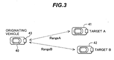
Fig. 3 is a diagram illustrating an exemplary positional relationship between objects under measurement and the distance measuring apparatus; -
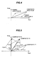
Fig. 4 is a diagram showing an exemplary power spectrum when a plurality of objects under measurement exist; -
Fig. 5 is a diagram showing an exemplary frequency spectrum; -
Fig. 6 is a processing flow chart for calculating the distance to an object under measurement in a method of transmitting three frequencies; -
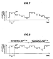
Fig. 7 is a diagram showing a change in a transmission signal frequency over time in a second embodiment of the present invention; -
Fig. 8 is a diagram showing a change in a transmission signal frequency over time in a third embodiment of the present invention; -
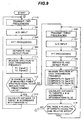
Fig. 9 is a processing flow chart for calculating the distance to an object under measurement in the third embodiment ; -
Fig. 10 is a diagram showing another example of a change in a transmission signal frequency over time; and -
Fig. 11 is an explanatory diagram for an example of a conventional two-frequency CW method. - In the following, embodiments of the present invention will be described with reference to
Figs. 1 through 10 . -
Fig. 1 is a block diagram of a radar apparatus (distance measuring apparatus) according to a first embodiment of the present invention, which is an example in which the present invention is applied to a distance measuring apparatus for an automotive vehicle. - In
Fig. 1 , atransmitter 18 transmits at a transmission frequency based on a modulatedsignal 19 from amodulator 17, and a transmitted high frequency signal is radiated from atransmission antenna 10. In the distance measuring apparatus for an automotive vehicle, a radio wave signal in a millimeter-wave band is typically used as the high frequency signal. - A
reception antenna 11 receives a radio wave signal reflected back from a target (object under measurement) such as a vehicle, an obstacle or the like, and amixer 12 performs a frequency conversion. Themixer 12 is supplied with a portion of the output signal of thetransmitter 18 through a directive coupler, so that a beat signal generated by mixing the signal from thetransmitter 18 and the received signal from thereception antenna 11 is sent from themixer 12 to ananalog circuit unit 13. - In a radar system for measuring a relative speed and distance utilizing the Doppler frequency, the beat signal outputted from the
mixer 12 is simply the Doppler frequency when using a homodyne-based reception system for directly converting to a baseband. - Then, the beat signal outputted from the
mixer 12 is supplied from theanalog circuit unit 13 to an A/D converter 14 which converts the beat signal to a digital signal that is then supplied to an FFT (fast Fourier transform)unit 15. ThisFFT unit 14 relies on a fast Fourier transform to measure the frequency spectrum of the beat signal as information of the amplitude and phase which is then sent to asignal processing unit 16. - Next,
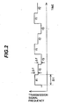
Fig. 2 shows an exemplary transmission signal in the distance measuring apparatus according to the first embodiment of the present invention. The example shown inFig. 2 represents a method of switching three transmission frequencies f1, f2, f3 over time. These three frequencies f1, f2, f3 are set such that differences between mutually adjacent frequencies (f1 and f2, f2 and f3) present the same difference value Δf. - As these three frequencies are alternately transmitted over time, received signals are measured at the respective frequencies to acquire information on the frequency spectra at the respective transmission frequencies.
- Consider now that two targets A, B have similar relative speeds and different distances, as illustrated in
Fig. 3 . In this event, reflected waves from the targets A, B have substantially the same Doppler frequencies for the respective transmission frequencies. For this reason, the power spectrum at the Doppler frequency corresponding to the relative speed of the targets A, B presents a composite signal of the reflected waves from the two targets A, B. - Specifically, a composite spectrum of the power spectrum A of the reflected wave from the target A and the power spectrum B from the target B is observed, as shown in
Fig. 4 . - When the two targets A, B having similar relative speeds are measured by the distance measuring apparatus configured to switch the three transmission frequencies f1, f2, f3, shown in
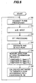
Fig. 2 , information on the frequency spectra of the received signals presents a vector as represented inFig. 5 . - Specifically, observed are three vectors, composite F1, composite F2, composite F3, which are composite vectors of the reflected waves from the two targets A, B. These composite vectors are combinations of the reflected waves (F1_A, F2_A, F3_A) from the target A, and the reflected waves (F1_B, F2_B, F3_B) from the target B at the transmission frequencies f1 - f3, which are combined at the respective transmission frequencies.
- Here, as described in connection with the aforementioned Equation (1), when the difference Δf of the transmission frequencies is constant, the phase difference of received signals for two transmission frequencies is proportional to the distance to the target A, so that the three vectors F1_A, F2_A, F3_A have their respective phase angles to adjacent vectors substantially identical to θA which is proportional to the distance Range A to the target A.
- Likewise, for the target B, the three vectors F1_B, F1_B, F3_B have their respective phase angles to adjacent vectors substantially identical to θB which is proportional to the distance Range B to the target B.
- Representing the three composite vectors Composite F1, Composite F2, Composite F3 in complex Signal(1) - Signal(3), the power spectra of received signals are expressed by the following Equation (2), based on F1_A, F1_B:


- The first and second rows of the Equation (2) are multiplied by exp(j·Δf·ra), and their upper and lower rows are subtracted from the products to derive the following Equation (3):

- In the Equation (3), from the fact that the difference f between the respective transmission frequencies is known, and the absolute value of the right side is 1, exp(j·Δf·ra) can be calculated.
- Also, exp(j·Δf·rb) can be calculated using the resulting exp(j·Δf·ra).
- An exemplary solution to them is shown below.
- First, exp(j·Δf·ra) is substituted as shown in the following Equation (4):

where x=tan(Δf·ra/2) - Next, since Signal(1), Signal(2), Signal(3) have known values, ra is calculated from the condition expressed by the following Equation (5) as a simultaneous equation for x:

where


- Also, Signal(1), Signal(2), Signal(3) are composite vectors (composite numbers) to be measured, and * indicates complex conjugates.
- Using the values calculated by the foregoing equations, the distance Range A to the target A, and the distance Range B to the target B are calculated by the following Equation (6):


- A processing flow for calculating the distances to the targets in the method of transmitting the foregoing three frequencies f1, f2, f3 will be described with reference to
Fig. 6 . - At
step 100 inFig. 6 , the three transmission frequencies f1, f2, f3 are alternately transmitted over time at timings as indicated inFig. 2 . The switching of these transmission frequencies f1, f2, f3 is implemented by a modulatedsignal 19 sent from themodulator 17 to theoscillator 18 shown inFig. 1 . - At
next step 101, a received signal reflected by a target is converted to a digital signal by the A/D converter 14. At thisstep 101, the sampling by the A/D converter 14 is performed a number of times equal to or larger than the number of sample points which are to undergo the FFT processing for each transmission frequency. - For example, when the number of sample points subjected to the FFT processing is N points which are sampled one by one in a transmission time Δt of each frequency shown in
Fig. 2 , a time (3xNxΔt) is required for sampling all of the three frequencies f1, f2, f3. - Next, at
step 102, the A/D inputted received signal is FFT processed by theFFT unit 15. This results in information on the frequency spectra of received signals at the three transmission frequencies f1, f2, f3. - Next, at
step 103, peak values are separated and detected from the information on the frequency spectra. In the radar system utilizing the Doppler frequency such as the two-frequency CW method, the frequency of a peak value is proportional to a relative speed, so that targets having different relative speeds are separated to detect respective peaks. - Next, at
step 104, the spectrum information with relative speeds having the same peak value is measured for each of the transmission frequencies f1, f2, f3. - Next, at
step 105, the distances to the two targets A, B, which are substantially equal in relative speed to each other, are calculated using Equation (5), Equation (6). - In the sequence of processing illustrated in
Fig. 6 , the processing after the separation and detection of the peaks atstep 103 to step 105 is executed by thesignal processing unit 16 inFig. 1 . - The processing from the foregoing
step 100 to step 105 is repeated to measure the distance, and calculate the distances between the two targets A, B, which are substantially equal in relative speed to each other, and a reference vehicle (observer). - In the foregoing manner, according to the first embodiment of the present invention, it is possible to realize a distance measuring apparatus which has a function of separating and detecting a plurality of targets with substantially equal relative speeds to the observer, and measuring the relative speeds, and the distance between each of the plurality of targets and the observer.
- Next, a second embodiment of the present invention will be described with reference to
Fig. 7 . - The first embodiment described with reference to
Figs. 1 through 6 is a method which involves switching three transmission frequencies f1, f2, f3 in order, separating and detecting two targets A, B, and calculating their relative speeds and distances. As is apparent from the measurement principles, in the method according to the present invention, an increase in the number of steps of transmitted frequencies results in a like increase in the amount of information on frequency spectra which can be measured. (N-1) targets can be separated and detected by utilizing the amount of information on frequency spectra under measurement, and providing N transmission frequencies. - Therefore, the second embodiment provides a method of sequentially switching four transmission frequencies f1, f2, f3, f4 over time, as shown in
Fig. 7 . Then, the frequency f2 is lower in frequency by Δf than f1, and the frequency f3 is lower in frequency by Δf than f2. Also, the frequency f4 is lower in frequency by Δf than f3. A transmission time at each frequency lasts for Δt which is equal to each other. - In this manner, by providing four transmission frequencies f1, f2, f3, f4, and using a distance measuring apparatus similar to the distance measuring apparatus illustrated in
Fig. 1 , i.e., in a manner similar to the first embodiment, relative speeds of three targets and the distances between the respective targets and the observer can be calculated in accordance with the flow chart illustrated inFig. 6 (however, the measurements of spectra and the like are made four times in conformity to the types of frequencies). - Therefore, according to the second embodiment, it is possible to realize a distance measuring apparatus which has a function of separating and detecting a plurality of or three targets with substantially equal relative speeds to the observer, and measuring their relative speeds and the distance between each of the targets and the observer.
- Moreover, it is contemplated to provide a method of transmitting five or more transmission frequencies in alternation to separate and detect a plurality of targets.
- Next, a third embodiment of the present invention will be described with reference to
Figs. 8 and9 . - As described in connection with the first embodiment, since the sampling by the A/
D converter 14 is performed a number of sample points, which undergo the FFT processing, or more, a total of time (2xNx Δ t) is required for sampling data which undergo the FFT processing when two frequencies are transmitted. Likewise, for transmitting three frequencies, a time (3xNxΔt) is required for sampling data which undergo the FFT processing. - Generally, since the distance measuring apparatus desirably detects targets, if any, in an early stage, the time required for sampling data for the FFT processing should be as short as possible.
- To meet this requirement, with a strategy which normally measures a distance at two alternating frequencies in accordance with the two-frequency CW method and switches at a certain timing to a method which additionally transmits a third frequency, it is possible to use, as required, the two-frequency CW method which only requires a short processing time, and a three-frequency based method which, though requiring a processing time not shorter than the two-frequency CW method, is capable of separating and measuring a plurality of targets which have substantially the same relative speeds.
- For the implementation which involves switching the two-frequency CW method and the three-frequency based method, signal transmission timings are shown in
Fig. 8 , and a processing flow is illustrated inFig. 9 . - As illustrated in
Fig. 8 , generally, the two-frequency CW method is relied on to measure distances at two alternating frequencies f1, f2, and a third frequency f3 is also added at a certain timing to transmit the frequencies f1, f2, f3 which are switched in sequence. - In a first time region in which the two frequencies f1, f2 are transmitted, the conventional two-frequency CW method is used to measure distances. In a second time region in which the third frequency is additionally transmitted, information on the three measured frequencies is utilized to separate and measure a plurality of targets having substantially the same relative speeds.
- For the timing at which the transmission of the two frequencies f1, f2 is switched to the transmission of the three frequencies f1, f2, f3, a temporal change in the power spectrum of a measured peak, for example, may be checked to see whether it is equal to or larger than a predetermined value.
- When a plurality of targets having the same relative speed exist, a measured frequency spectrum appears to be a signal which is a combination of reflected waves from the plurality of targets, as shown in
Fig. 4 . - A reflected wave from each target varies in amplitude over time due to the influence of multipath or the like, so that the measured composite spectrum largely varies in amplitude and phase over time.
Fig. 9 illustrates a processing flow for switching a time region in which the two frequencies f1, f2 are transmitted and a time region in which the three frequencies f1, f2, f3 are transmitted, making use of the foregoing characteristics. - In
Fig. 9 , generally, the two frequencies f1, f2 are alternately transmitted atstep 110. While the processing fromstep 101 to step 103 is similar to the processing described in the flow chart ofFig. 6 , a time required for sampling the number of points subjected to the FFT processing is (2xNxΔt) since measurements are made at the two frequencies in this time region. - Next, at
step 111, the power spectra of received signals are measured at the respective transmission frequencies f1, f2. Subsequently, atstep 112, it is determined whether or not the amounts of variations in the amplitude and phase of the measured power spectra over time are equal to or larger than predetermined values. As the predetermined values in this determination, for example, if the amounts of variations in the amplitude and phase over time are equal to or larger than 30 %, the amounts of variations over time may be determined as large. - When it is determined at
step 112 that variations in the measured power spectra over time are equal to or smaller than the predetermined values, the flow proceeds to step 113, where the distances to the targets are calculated using Equation (1), followed by a repetition of measurements of distances using the two frequencies f1, f2 fromstep 110. - When the amounts of variations in the amplitude and phase of the measured power spectra over time are equal to or larger than the predetermined values, the flow proceeds to step 100, where the three frequencies f1, f2, f3 are alternately transmitted at timings as indicated in the time region of the three-frequency based measurement in
Fig. 8 . - Next, similar to the processing described in the flow chart of
Fig. 6 , the processing fromstep 101 to step 105 is performed to measure the distances to the two targets A, B. In this event, since the three frequencies f1, f2, f3 are being alternately transmitted, a time required for sampling the number of points subjected to the FFT processing amounts to (3xNxΔt). - Next, it is determined at
step 114 whether or not there are a plurality of targets which have the same speed. When there are a plurality of targets having the same relative speed, the flow returns to step 100, where the processing for transmitting the three frequencies f1, f2, f3 is continued. - When it is determined at
step 114 that there are not a plurality of targets having the same relative speed, the flow returns to step 110, where the two-frequency based measurement is performed by transmitting the two frequencies f1, f2. - By thus providing the time region in which the two frequencies f1, f2 are transmitted, and the time region in which the three frequencies f1, f2, f3 are transmitted, the existence of targets can be normally measured in a short time of (2xNx Δt), and when a plurality of targets can exist, the respective distances to the plurality of targets can be measured by using the three frequencies f1, f2, f3.
- In the foregoing manner, according to the third embodiment of the present invention, in addition to the ability to provide similar effects to those of the first embodiment, it is possible to realize a distance measuring apparatus which can use, as required, the two-frequency CW method that requires a shorter processing time, and the three-frequency based method that, though a longer processing time is required than the two-frequency CW method, is capable of separating and measuring a plurality of targets which have substantially the same relative speeds.
- As previously shown in the foregoing embodiment, the switching of the number of transmitted frequencies at a certain timing may be applied, for example, to switching from the transmission of the two frequencies f1, f2 to the transmission of N frequencies, where N is four or more.
- Also, as shown in
Fig. 10 , the third frequency f3 and fourth frequency f4 are alternately transmitted within a certain time period. Specifically, even when the frequencies are alternated such as f1 -> f2 -> f3 -> f1 -> f2 -> f4, three targets can be separately measured, making use of information on the four measured frequencies f1, f2, f3, f4, as described in the foregoing embodiment. - In the embodiment of
Fig. 10 , a time required for sampling the number of points subjected to the FFT processing amounts to (3xNxΔt) for the two transmission frequencies f1,f2, while a time required for sampling the number of points subjected to the FFT processing amounts to (6xNxΔt) for the transmission frequencies f3, f4. - While in the foregoing example, a single transmitter is provided for transmitting a plurality of frequencies, a plurality of transmitters may be provided to transmit a plurality of frequencies from the plurality of transmitters. However, when a plurality of transmitters are provided, the frequencies must be adjusted among the plurality of transmitters, and the weight is increased. On the other hand, when a single transmitter is provided alone such that a plurality of frequencies are transmitted from the signal transmitter, no adjustment is required for the frequencies among a plurality of transmitters, and the weight is reduced.
- The time Δt for which one frequency signal is continued should be equal to or longer than a time taken for a radio wave to go and return the distance to a target.
- Also, while the foregoing example is an example in which the present invention is applied to a distance measuring apparatus for an automotive vehicle, the present invention is not limited to a use for automotive vehicle but may be applied to other distance measuring apparatus.
- For example, the present invention can be applied to a system which comprises a distance measuring apparatus installed near a road to determine a speed of a running vehicle, and vehicles which are running at that speed.
- Also, the present invention can be applied to a system which comprises a distance measuring apparatus installed near a blind road to notify how many automotive vehicles are approaching a curve at which speeds.
- The present invention can also be applied to an apparatus for detecting objects under measurement, which recognizes a plurality of objects under measurement.
Specifically, the present invention can also be applied, for example, to an apparatus for detecting objects under measurement, which separates and recognizes the positions of a plurality of pedestrians going ahead or the like, and displays them in a vehicle, when the vehicle is being driven at night. In this case, a means for separating and detecting the respective positions of a plurality of pedestrians or the like is thesignal processing unit 16. - According to the present invention, by providing a first separating/detecting means having a function of transmitting a certain constant first frequency for a predetermined time or more, transmitting a second frequency having a certain frequency difference from the first frequency for a predetermined time or more, and transmitting an nth frequency having a frequency difference of an integer multiple equal to or larger than two of the frequency difference from the first frequency for a predetermined time or more, and for measuring the Doppler frequencies of reflected waves from objects under measurement at the respective transmission frequencies to separate and detect the objects under measurement at each Doppler frequency, and a second separating/detecting means for separating objects under measurement having the same Doppler frequency from phase information and amplitude information of received signals acquired at each transmission frequency, it is possible to realize a distance measuring apparatus which is capable of separating and detecting a plurality of objects under measurement having substantially the same relative speeds, and calculating the distance between each of the plurality of objects under measurement and an observer.
- Also, by virtue of the ability to separate and detect a plurality of objects under measurement having substantially the same relative speeds, it is possible to realize an apparatus for detecting objects under measurement, which is capable of separating each of a plurality of pedestrians or the like, which are moving at the same relative speed, and recognizing their existence at night or the like.
Claims (4)
- A distance measuring apparatus which radiates a radio wave, receives a reflected wave from an object under measurement, and detects the object under measurement, said distance measuring apparatus comprising:transmitting means (10, 18) configured to continuously transmit for a predetermined time or more a first frequency signal and a second frequency signal having a predetermined frequency differenceΔt from the first frequency, said transmitting means (10, 18) is further configured to transmit N further frequency signals wherein the frequency difference between mutually adjacent frequencies of said N frequency signals is Δf and wherein a frequency difference between the first frequency and any of the N further frequency signals is at least an integer multiple of m*Δf, where N is an integer value equal to or larger than 1 and m is an integer value equal to or larger than 2;receiving means (11, 12, 13, 14, 15) for measuring a Doppler frequency of the reflected wave from said object under measurement at each of the respective transmission frequencies of said first frequency, second frequency, and N frequencies:detection processing means (16) for separating a plurality of objects under measurement to detect the respective objects;characterized in thatsaid transmitting means (10, 18) is further configured to have a first mode wherein said first frequency signal and said second frequency signal are alternately transmitted over time,said transmitting means is further configured to have second mode in which said first frequency signal, said second frequency signal and said N further frequency signals are respectively transmitted alternately over time; andwherein the distance measuring apparatus switches from the first mode into the second mode when an amount of variation in the amplitude and phase of the measured power spectra over time is equal to or larger than a predetermined value.
- A distance measuring apparatus according to claim 1, characterized in that said N is one.
- A distance measuring apparatus according to claim 1 or 2, characterized in that:said detection processing means (16) has a first separation/detection function for separating and detecting an object under measurement at each Doppler frequency of received signals, and a second separation/detection function for measuring phase information and amplitude information on received Doppler frequencies, and separating and detecting a plurality of objects under measurement having substantially the same Doppler frequencies from the phase information and amplitude information.
- A distance measuring apparatus according to claim 1, 2 or 3, characterized in that:said transmitting means (10, 18) has a single transmitter (18), wherein a plurality of frequencies are periodically alternately transmitted by the single oscillator (18).
Applications Claiming Priority (1)
| Application Number | Priority Date | Filing Date | Title |
|---|---|---|---|
| PCT/JP2000/000464 WO2001055745A1 (en) | 2000-01-28 | 2000-01-28 | Distance measuring device |
Publications (3)
| Publication Number | Publication Date |
|---|---|
| EP1253441A1 EP1253441A1 (en) | 2002-10-30 |
| EP1253441A4 EP1253441A4 (en) | 2008-12-31 |
| EP1253441B1 true EP1253441B1 (en) | 2010-04-07 |
Family
ID=11735632
Family Applications (1)
| Application Number | Title | Priority Date | Filing Date |
|---|---|---|---|
| EP00993805A Expired - Lifetime EP1253441B1 (en) | 2000-01-28 | 2000-01-28 | Distance measuring device |
Country Status (5)
| Country | Link |
|---|---|
| US (1) | US6703967B1 (en) |
| EP (1) | EP1253441B1 (en) |
| JP (1) | JP3746235B2 (en) |
| DE (1) | DE60044148D1 (en) |
| WO (1) | WO2001055745A1 (en) |
Families Citing this family (64)
| Publication number | Priority date | Publication date | Assignee | Title |
|---|---|---|---|---|
| JP3395623B2 (en) * | 1998-01-19 | 2003-04-14 | 株式会社日立製作所 | Vehicle travel control device |
| JP3527979B2 (en) * | 2001-10-19 | 2004-05-17 | オプテックス株式会社 | Microwave sensor |
| WO2003048801A1 (en) * | 2001-11-28 | 2003-06-12 | Siemens Aktiengesellschaft | Fmcw radar with restricted emission time to avoid aliasing effects |
| JP3688255B2 (en) | 2002-09-20 | 2005-08-24 | 株式会社日立製作所 | In-vehicle radio radar apparatus and signal processing method thereof |
| EP1450128A1 (en) * | 2003-02-19 | 2004-08-25 | Leica Geosystems AG | Method and device for extracting geodesic distance information |
| JP4258328B2 (en) * | 2003-09-12 | 2009-04-30 | オムロン株式会社 | Two-frequency Doppler distance measuring device and detection system provided with the device |
| JP2005156337A (en) * | 2003-11-26 | 2005-06-16 | Hitachi Ltd | On-vehicle radar device |
| EP1711844B1 (en) * | 2004-01-20 | 2009-10-14 | BAE SYSTEMS Information and Electronic Systems Integration Inc. | Multiple frequency through-the-wall motion detection and ranging using difference-based estimation technique |
| US7460052B2 (en) | 2004-01-20 | 2008-12-02 | Bae Systems Information And Electronic Systems Integration Inc. | Multiple frequency through-the-wall motion detection and ranging using a difference-based estimation technique |
| DE102004054466A1 (en) * | 2004-11-11 | 2006-06-08 | Robert Bosch Gmbh | Radar system, in particular for distance and / or speed measurement |
| JP4665962B2 (en) * | 2005-02-08 | 2011-04-06 | 三菱電機株式会社 | Target detection device |
| US20060238742A1 (en) * | 2005-04-25 | 2006-10-26 | Hunt Jeffrey H | Short duty cycle lidar |
| NL1031209C2 (en) * | 2006-02-22 | 2007-08-24 | Enraf Bv | Method and device for accurately determining the level L of a liquid with the aid of radar signals radiated to the liquid level and radar signals reflected by the liquid level. |
| JP4950537B2 (en) * | 2006-03-31 | 2012-06-13 | セコム株式会社 | Moving object detection device |
| SG137726A1 (en) * | 2006-06-06 | 2007-12-28 | Sony Corp | A method and apparatus for measuring distance between a target and a receiver in a ranging system |
| JP2008145425A (en) * | 2006-11-13 | 2008-06-26 | Toyota Central R&D Labs Inc | Radar device |
| JP4724694B2 (en) * | 2007-08-08 | 2011-07-13 | 日立オートモティブシステムズ株式会社 | Radio radar equipment |
| US8995226B2 (en) | 2008-05-06 | 2015-03-31 | Bios Developments Limited | Measurement method and apparatus |
| GB0808189D0 (en) * | 2008-05-06 | 2008-06-11 | Rudd Wayne | Measurement method and apparatus |
| US8102261B2 (en) | 2008-07-17 | 2012-01-24 | Honeywell International Inc. | Microwave ranging sensor |
| US8159344B2 (en) * | 2008-10-28 | 2012-04-17 | Honeywell International, Inc. | Microwave motion detectors utilizing multi-frequency ranging and target angle detection |
| US8279112B2 (en) * | 2008-11-03 | 2012-10-02 | Trimble Navigation Limited | Methods and apparatuses for RFID tag range determination |
| US7791528B2 (en) * | 2008-11-24 | 2010-09-07 | Autoliv Asp, Inc. | Method and apparatus for radar signal processing |
| US8125373B2 (en) * | 2010-07-23 | 2012-02-28 | Toyota Motor Engineering & Manufacturing North America, Inc. | Microwave system utilizing elevational scanning by frequency hopping |
| JP5732706B2 (en) * | 2010-10-19 | 2015-06-10 | 公益財団法人北九州産業学術推進機構 | Ultra-wideband pulse sensor |
| US9983294B2 (en) * | 2013-02-01 | 2018-05-29 | Mitsubishi Electric Corporation | Radar system |
| KR101357120B1 (en) * | 2013-04-23 | 2014-02-05 | 김태민 | Method of measuring distance based on optical signals and apparatuse thereof |
| TWI474030B (en) * | 2013-07-10 | 2015-02-21 | U & U Engineering Inc | Vehicle detector and method for measuring distance and velocity of vehicle |
| JP5990761B2 (en) * | 2013-10-03 | 2016-09-14 | トヨタ自動車株式会社 | Radar equipment |
| US9784820B2 (en) * | 2014-09-19 | 2017-10-10 | Delphi Technologies, Inc. | Radar system with phase based multi-target detection |
| DE102015102929B3 (en) * | 2015-03-02 | 2016-02-04 | Karlsruher Institut für Technologie | Method of operating a CW radar detector and CW radar detector |
| JP6610116B2 (en) * | 2015-09-18 | 2019-11-27 | 日本電気株式会社 | Target information measuring apparatus and target information measuring method |
| DE102016119473B4 (en) | 2015-10-15 | 2022-10-20 | Nidec Elesys Corporation | Waveguide device and antenna device with the waveguide device |
| DE112016000178B4 (en) | 2015-11-05 | 2023-06-22 | Nidec Corporation | slot antenna |
| JP6238505B1 (en) | 2015-11-05 | 2017-11-29 | 日本電産株式会社 | Slot array antenna |
| DE102016125419B4 (en) | 2015-12-24 | 2022-10-20 | Nidec Elesys Corporation | Waveguide device, slot antenna and radar, radar system, and wireless communication system with the slot antenna |
| US10381741B2 (en) | 2015-12-24 | 2019-08-13 | Nidec Corporation | Slot array antenna, and radar, radar system, and wireless communication system including the slot array antenna |
| JP6809908B2 (en) | 2016-01-15 | 2021-01-06 | 日本電産株式会社 | A waveguide device and an antenna device including the waveguide device |
| WO2017131099A1 (en) | 2016-01-29 | 2017-08-03 | Nidec Elesys Corporation | Waveguide device, and antenna device including the waveguide device |
| DE102017102284A1 (en) | 2016-02-08 | 2017-08-10 | Nidec Elesys Corporation | Waveguide device and antenna device with the waveguide device |
| DE102017102559A1 (en) | 2016-02-12 | 2017-08-17 | Nidec Elesys Corporation | Waveguide device and antenna device with the waveguide device |
| JP2019047141A (en) | 2016-03-29 | 2019-03-22 | 日本電産エレシス株式会社 | Microwave IC waveguide device module, radar device and radar system |
| CN208093770U (en) | 2016-04-05 | 2018-11-13 | 日本电产株式会社 | Wireless communication system |
| US10884114B2 (en) * | 2016-04-19 | 2021-01-05 | Mitsubishi Electric Corporation | Radar device |
| JP2019054315A (en) | 2016-04-28 | 2019-04-04 | 日本電産エレシス株式会社 | Mounting board, waveguide module, integrated circuit mounting board, microwave module, radar device and radar system |
| JP7182560B2 (en) * | 2017-01-04 | 2022-12-02 | アルプスアルパイン株式会社 | personal radar |
| JP2018164252A (en) | 2017-03-24 | 2018-10-18 | 日本電産株式会社 | Slot array antenna, and radar having the same |
| CN108695585B (en) | 2017-04-12 | 2021-03-16 | 日本电产株式会社 | Method for manufacturing high-frequency component |
| JP7020677B2 (en) | 2017-04-13 | 2022-02-16 | 日本電産エレシス株式会社 | Slot antenna device |
| US10608345B2 (en) | 2017-04-13 | 2020-03-31 | Nidec Corporation | Slot array antenna |
| CN108736166B (en) | 2017-04-14 | 2020-11-13 | 日本电产株式会社 | Slot antenna device and radar device |
| JP2020520180A (en) | 2017-05-11 | 2020-07-02 | 日本電産株式会社 | Waveguide device and antenna device including the waveguide device |
| DE112018002020T5 (en) | 2017-05-11 | 2020-01-09 | Nidec Corporation | WAVE GUIDE DEVICE AND ANTENNA DEVICE WITH THE WAVE GUIDE DEVICE |
| US10547122B2 (en) | 2017-06-26 | 2020-01-28 | Nidec Corporation | Method of producing a horn antenna array and antenna array |
| JP2019009779A (en) | 2017-06-26 | 2019-01-17 | 株式会社Wgr | Transmission line device |
| JP7103860B2 (en) | 2017-06-26 | 2022-07-20 | 日本電産エレシス株式会社 | Horn antenna array |
| JP2019012999A (en) | 2017-06-30 | 2019-01-24 | 日本電産株式会社 | Waveguide device module, microwave module, radar device, and radar system |
| JP7294608B2 (en) | 2017-08-18 | 2023-06-20 | ニデックエレシス株式会社 | antenna array |
| JP2019050568A (en) | 2017-09-07 | 2019-03-28 | 日本電産株式会社 | Directional coupler |
| US20190109361A1 (en) | 2017-10-10 | 2019-04-11 | Nidec Corporation | Waveguiding device |
| JP7298808B2 (en) | 2018-06-14 | 2023-06-27 | ニデックエレシス株式会社 | slot array antenna |
| CN111446530A (en) | 2019-01-16 | 2020-07-24 | 日本电产株式会社 | Waveguide device, electromagnetic wave locking device, antenna device, and radar device |
| JP2020165811A (en) * | 2019-03-29 | 2020-10-08 | 古河電気工業株式会社 | Position estimating device and position estimating method |
| JP7433999B2 (en) | 2020-03-13 | 2024-02-20 | 日清紡マイクロデバイス株式会社 | Distance calculation device, distance measurement system, distance calculation program and distance calculation method |
Family Cites Families (13)
| Publication number | Priority date | Publication date | Assignee | Title |
|---|---|---|---|---|
| US3750172A (en) * | 1971-06-02 | 1973-07-31 | Bendix Corp | Multifrequency cw radar with range cutoff |
| US5646623A (en) * | 1978-05-15 | 1997-07-08 | Walters; Glenn A. | Coherent, frequency multiplexed radar |
| SE456867B (en) * | 1985-12-12 | 1988-11-07 | Stiftelsen Inst Mikrovags | SET MEASURING DISTANCE AND / OR SPEED BETWEEN TWO OBJECTIVES |
| US5189426A (en) * | 1991-05-06 | 1993-02-23 | Ivhs Technologies, Inc. | Doppler frequency spectrum de-emphasis for automotive collision avoidance radar system |
| US5134411A (en) | 1990-07-13 | 1992-07-28 | General Microwave Corporation | Near range obstacle detection and ranging aid |
| GB2249448B (en) | 1990-10-30 | 1995-01-25 | Roke Manor Research | Improvements in or relating to radar systems |
| JP2989428B2 (en) * | 1993-06-17 | 1999-12-13 | 本田技研工業株式会社 | Time-sharing FM radar system |
| JP3550829B2 (en) | 1995-01-24 | 2004-08-04 | 株式会社デンソー | FM-CW radar device |
| JP3491418B2 (en) | 1995-12-01 | 2004-01-26 | 株式会社デンソー | FMCW radar equipment |
| SE507996C2 (en) * | 1996-09-18 | 1998-08-10 | Celsiustech Electronics Ab | Procedure for determining the relative velocity between two objects in motion |
| FR2757639B1 (en) | 1996-12-20 | 1999-03-26 | Thomson Csf | RADAR FOR DETECTING OBSTACLES IN PARTICULAR FOR MOTOR VEHICLES |
| FR2761480B1 (en) * | 1997-03-28 | 1999-06-11 | Thomson Csf | METHOD AND DEVICE FOR REMOTE AMBIGUITY REMOTE APPLIED IN PARTICULAR TO A CONTINUOUS WAVE AND FREQUENCY JUMP RADAR |
| JPH11133143A (en) | 1997-10-31 | 1999-05-21 | Toyota Motor Corp | Radar device |
-
2000
- 2000-01-28 DE DE60044148T patent/DE60044148D1/en not_active Expired - Lifetime
- 2000-01-28 US US10/069,593 patent/US6703967B1/en not_active Expired - Fee Related
- 2000-01-28 EP EP00993805A patent/EP1253441B1/en not_active Expired - Lifetime
- 2000-01-28 JP JP2001555830A patent/JP3746235B2/en not_active Expired - Fee Related
- 2000-01-28 WO PCT/JP2000/000464 patent/WO2001055745A1/en active Application Filing
Also Published As
| Publication number | Publication date |
|---|---|
| DE60044148D1 (en) | 2010-05-20 |
| JP3746235B2 (en) | 2006-02-15 |
| EP1253441A4 (en) | 2008-12-31 |
| WO2001055745A1 (en) | 2001-08-02 |
| EP1253441A1 (en) | 2002-10-30 |
| US6703967B1 (en) | 2004-03-09 |
Similar Documents
| Publication | Publication Date | Title |
|---|---|---|
| EP1253441B1 (en) | Distance measuring device | |
| JP4665962B2 (en) | Target detection device | |
| EP1757953B1 (en) | FM-CW radar system | |
| US6606052B1 (en) | Method and apparatus for detecting multiple objects with frequency modulated continuous wave radar | |
| EP2026098B1 (en) | Radar apparatus | |
| EP0777133B1 (en) | FM-CW radar apparatus for measuring relative speed of and distance to an object | |
| EP1464986B1 (en) | Radar apparatus | |
| US20110122013A1 (en) | Radar apparatus | |
| US11105919B2 (en) | Vehicle radar for environmental detection | |
| JP3821688B2 (en) | Radar equipment | |
| US7671788B2 (en) | Apparatus and method for suppression of unnecessary signals in a radar system | |
| CN102540190A (en) | Fmcw radar apparatus having a plurality of processor cores used for signal processing | |
| CN1890578B (en) | Measuring device for a motor vehicle | |
| EP2096457B1 (en) | Digital beam forming using frequency-modulated signals | |
| JP2009109417A (en) | Radar system and radar mounting mobile device | |
| EP3779498B1 (en) | Velocity measurement device, velocity measurement program, recording medium, and velocity measurement method | |
| EP3796038A1 (en) | Object range and velocity detection from varying radar pulse repetition times | |
| EP3742196B1 (en) | Radar device | |
| JP3482870B2 (en) | FM-CW radar device | |
| JP2001242240A (en) | Obstruction detecting method, radar device and on- vehicle radar device | |
| KR20070096009A (en) | Target detecting device | |
| JP2002323557A (en) | Fm-cw radar device |
Legal Events
| Date | Code | Title | Description |
|---|---|---|---|
| PUAI | Public reference made under article 153(3) epc to a published international application that has entered the european phase |
Free format text: ORIGINAL CODE: 0009012 |
|
| 17P | Request for examination filed |
Effective date: 20020819 |
|
| AK | Designated contracting states |
Kind code of ref document: A1 Designated state(s): AT BE CH CY DE DK ES FI FR GB GR IE IT LI LU MC NL PT SE |
|
| AX | Request for extension of the european patent |
Free format text: AL;LT;LV;MK;RO;SI |
|
| RBV | Designated contracting states (corrected) |
Designated state(s): DE FR |
|
| A4 | Supplementary search report drawn up and despatched |
Effective date: 20081128 |
|
| 17Q | First examination report despatched |
Effective date: 20090327 |
|
| GRAP | Despatch of communication of intention to grant a patent |
Free format text: ORIGINAL CODE: EPIDOSNIGR1 |
|
| GRAS | Grant fee paid |
Free format text: ORIGINAL CODE: EPIDOSNIGR3 |
|
| GRAA | (expected) grant |
Free format text: ORIGINAL CODE: 0009210 |
|
| RAP1 | Party data changed (applicant data changed or rights of an application transferred) |
Owner name: HITACHI, LTD. |
|
| AK | Designated contracting states |
Kind code of ref document: B1 Designated state(s): DE FR |
|
| REF | Corresponds to: |
Ref document number: 60044148 Country of ref document: DE Date of ref document: 20100520 Kind code of ref document: P |
|
| PLBE | No opposition filed within time limit |
Free format text: ORIGINAL CODE: 0009261 |
|
| STAA | Information on the status of an ep patent application or granted ep patent |
Free format text: STATUS: NO OPPOSITION FILED WITHIN TIME LIMIT |
|
| 26N | No opposition filed |
Effective date: 20110110 |
|
| PGFP | Annual fee paid to national office [announced via postgrant information from national office to epo] |
Ref country code: FR Payment date: 20120202 Year of fee payment: 13 |
|
| PGFP | Annual fee paid to national office [announced via postgrant information from national office to epo] |
Ref country code: DE Payment date: 20120125 Year of fee payment: 13 |
|
| REG | Reference to a national code |
Ref country code: FR Ref legal event code: ST Effective date: 20130930 |
|
| PG25 | Lapsed in a contracting state [announced via postgrant information from national office to epo] |
Ref country code: DE Free format text: LAPSE BECAUSE OF NON-PAYMENT OF DUE FEES Effective date: 20130801 |
|
| REG | Reference to a national code |
Ref country code: DE Ref legal event code: R119 Ref document number: 60044148 Country of ref document: DE Effective date: 20130801 |
|
| PG25 | Lapsed in a contracting state [announced via postgrant information from national office to epo] |
Ref country code: FR Free format text: LAPSE BECAUSE OF NON-PAYMENT OF DUE FEES Effective date: 20130131 |