EP1253435A1 - Procédé et dispositif d'estimation spatio-temporelle d'un ou de plusieurs émetteurs - Google Patents
Procédé et dispositif d'estimation spatio-temporelle d'un ou de plusieurs émetteurs Download PDFInfo
- Publication number
- EP1253435A1 EP1253435A1 EP02291003A EP02291003A EP1253435A1 EP 1253435 A1 EP1253435 A1 EP 1253435A1 EP 02291003 A EP02291003 A EP 02291003A EP 02291003 A EP02291003 A EP 02291003A EP 1253435 A1 EP1253435 A1 EP 1253435A1
- Authority
- EP
- European Patent Office
- Prior art keywords
- transmitter
- transmitters
- paths
- sources
- separation
- Prior art date
- Legal status (The legal status is an assumption and is not a legal conclusion. Google has not performed a legal analysis and makes no representation as to the accuracy of the status listed.)
- Granted
Links
Images

Classifications
-
- G—PHYSICS
- G01—MEASURING; TESTING
- G01S—RADIO DIRECTION-FINDING; RADIO NAVIGATION; DETERMINING DISTANCE OR VELOCITY BY USE OF RADIO WAVES; LOCATING OR PRESENCE-DETECTING BY USE OF THE REFLECTION OR RERADIATION OF RADIO WAVES; ANALOGOUS ARRANGEMENTS USING OTHER WAVES
- G01S3/00—Direction-finders for determining the direction from which infrasonic, sonic, ultrasonic or electromagnetic waves, or particle emission, not having a directional significance, are being received
- G01S3/02—Direction-finders for determining the direction from which infrasonic, sonic, ultrasonic or electromagnetic waves, or particle emission, not having a directional significance, are being received using radio waves
- G01S3/74—Multi-channel systems specially adapted for direction-finding, i.e. having a single antenna system capable of giving simultaneous indications of the directions of different signals
Definitions
- the present invention relates to a method for spatio-temporal estimation of one or more transmitters in an antenna network when the wave transmitted by a transmitter propagates in the form of multipaths.
- Multipaths exist when a wave emitted by a transmitter propagates along several paths towards a receiver or a direction finding system. The multiple paths are due in particular to the presence of obstacles present between a transmitter and a receiver.
- the field of the invention relates in particular to that of the direction finding of radioelectric sources, the word source designating a transmitter.
- the term goniometry means an “estimate of incidences”. It is also that of spatial filtering which aims to synthesize an antenna in the direction of each of the transmitters from an array of antennas.
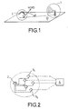
- a conventional direction finding system aims to estimate the incidence of a transmitter, that is to say the angles of arrival of incident radio waves on a network 1 of N sensors of a reception system 2 , for example a network of several antennas as shown in FIGS. 1 and 2.
- the network of N sensors is coupled to a computing device 4 via N receivers in order to estimate the angles of incidence ⁇ p of radio waves emitted by different p sources or transmitters and which are received by the network.
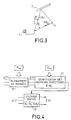
- the wave emitted by the transmitter can propagate along several paths according to a diagram given in Figure 3.
- the wave k ( ⁇ d ) has a direct path of incidence ⁇ d and the wave k ( ⁇ r ) a reflected path of incidence ⁇ r .
- the multipaths are caused in particular by obstacles 5 located between the transmitter 6 and the reception system 7.
- the different paths arrive with different incidences ⁇ op where p corresponds to the poor path.
- the multipaths follow different propagation paths and are therefore received at different times t mp .
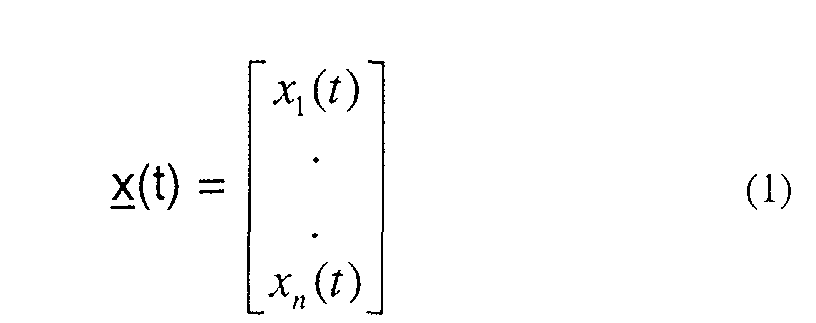
- the N antennas of the reception system receive the signal x n (t) where n is the index of the sensor. From these N signals x n (t) we construct the observation vector:
- the prior art describes different techniques of direction finding, source separation, and direction finding after source separation. These techniques consist in estimating the signals s m (t- ⁇ mp ) from the observation vector x (t) without any knowledge of their temporal properties. These techniques are said to be blind. The only assumption is that the signals s m (t- ⁇ mp ) are statistically independent for a path p such that 1 ⁇ p ⁇ P m and an emitter m such as 1 ⁇ m ⁇ M.
- the estimate of R xx used is such that: where T corresponds to the integration period.
- quadricovariance is defined in order 4 whose elements are the cumulants of the sensor signals x n (t):
- Q xx (i, j, k, l) cum ⁇ x i (t), x j (t) *, x k (t) *, x l (t) ⁇
- the elements Q xx (i, j, k, l) are stored in a matrix Q xx at line number N (jl) + i and at column number N (l-1) + k.
- Q xx is therefore a matrix of dimension N 2 xN 2 .
- Figure 3 shows schematically the principle of this separation method based on the statistical independence of the sources: under these conditions the matrices R ss and Q ss of expressions (6) and (10) are diagonal.
- the algorithm for processing the observation vector corresponding to the signals received on the sensor network is composed of a step of whitening the data x (t) leading to an observation vector z (t) and an identification step 11 of the guiding vectors optionally followed by a spatial filtering step 12 using the signal vector x (t) to obtain an estimated signal vector s and '(k).
- the bleaching step uses the covariance matrix R xx in order to orthonormalize the base of the directing vectors a ( ⁇ 1 ) ... a ( ⁇ M ).
- the second identification step uses the quadricovariance Q zz to identify the previously orthonormalized directing vectors.
- the purpose of bleaching is to orthogonalize the mixing matrix A to be estimated. For that it is necessary to multiply the observations x (t) by a matrix ⁇ -1 such that the covariance matrix of the non-noisy and whitewashed observations is equal to the identity.
- ⁇ s is a diagonal matrix of dimension MxM containing the M strongest eigenvalues of R xx .
- the matrix E s of dimension NxM is composed of the eigenvectors associated with the strongest eigenvalues of R xx and the matrix E b of dimension Nx (NM) is composed of the eigenvectors associated with the eigenvalue of noise ⁇ 2 .
- This step is to identify the unitary matrix U composed of the M whitened directing vectors t m .
- Each vector e m of length M 2 is then transformed into a matrix U m of dimension (M ⁇ M) whose columns are the M M-tuples constituting the vector e m . which is also written according to equation (24): where ⁇ m is a diagonal matrix of elements ⁇ mi .
- ⁇ m is a diagonal matrix of elements ⁇ mi .
- ⁇ bm I NOT - at ' m at ' m H at ' m H . at ' m for 1 ⁇ m ⁇ M
- the invention relates to a method and a device which enable in particular to determine, for each transmitter propagating in the form of multi-path, the incidence of angles of arrival for multi-path.
- the objective of the present invention is to carry out selective direction-finding by transmitter in the presence of multi-paths, that is to say for P m > 1.
- One of the methods implemented by the invention is to group the signals received by transmitter, before performing the direction finding of all these multi-paths for each transmitter, for example.
- Another way to do this is to separate sources or transmitters spatio-temporally.
- the invention relates to a method for spatio-temporal estimation of the angles of incidence of several transmitters in an antenna network characterized in that it comprises at least one step of separating the transmitters, and a step of determining the different angles of arrival at the middle of the multipaths p emitted by each of the transmitters.
- the method comprises at least one step of separating the transmitters in order to obtain the different signals s (t) received by the antenna array, a step of grouping the different signals by transmitter and a step of determination of the different angles ⁇ mid of the multi-paths by transmitter.
- the method comprises a spatio-temporal separation step of the different transmitters before determining the angles of arrival ⁇ mi.
- the spatio-temporal separation step comprises for example a step where for a given transmitter the signal s m (t) is delayed, thus assimilating the delayed signal to the output of a filter of length L m , the inputs of which are s m (t) to s m (t- ⁇ m ), before applying source separation.
- the method may include a step of identifying and eliminating the outputs associated with the same transmitter after determining the angles ⁇ mi .
- the method uses, for example, methods of goniometry of all types, such as high resolution methods such as MUSIC in particular, methods by interferometry, etc ...
- the invention also relates to a device for carrying out an estimate. space-time of a set of transmitters which emit propagating waves in the form of multipaths in a network of N sensors characterized in that it includes a computer adapted to implement the steps of the characterized process by the steps given above.
- the method according to the invention notably makes it possible to carry out a separate direction finding of transmitters. Thus, only the incidences of the multipaths of a given transmitter are determined.
- the acquisition system which is described in FIG. 2 comprises a network 2 consisting of N antennas 3 1 to 3 N in connection with a computer 4 adapted in particular to implement the different steps of the method according to the invention.
- the computer is for example suitable for determining the angles of arrival for each transmitter 1i (FIG. 1) emitting a wave which can propagate in the form of multi-paths in accordance with the diagram of FIG. 1.
- the computer is provided with means making it possible to perform the direction finding of each of the 1i transmitters.
- the sensors or antennas of the reception system receive signals x n (t) as described above, which makes it possible, from the N antennas, to construct the observation vector x (t).
- the idea of the method according to the invention is to carry out a direction finding separated from the transmitters when the wave or waves propagate in the form of multi-routes, either by grouping the different outputs by transmitter, or by introducing a step of separation of spatio-temporal sources before carrying out the goniometry for each transmitter.
- the vector s '(t) of component s and' mp (t) can be written in the following form:
- the intercorrelation function r kk ' ( ⁇ ) between the signals u k (t) and u k' (t) is non-zero when they are associated with the same transmitter.
- r kk ' ( ⁇ ) E [u k (t) u k ' (t- ⁇ ) *] ⁇ 0 for ⁇ > 0 and k ⁇ k '
- the method comprises for example a step of searching for the value of the delay which maximizes the intercorrelation between the outputs u k (t) and u k ' (t- ⁇ ) and a step of memorizing the indices k and k' when the maximum is greater than a threshold.
- Figure 6 summarizes an example of implementation of the technique of grouping including the correlation test.
- the computer searches for the values of the delays ⁇ for which the energy received by the antenna array is maximum, by performing a two-by-two intercorrelation of the signals originating from the separation of the sources 30, 31 , 32, function r kk ' ( ⁇ ). It stores the selected paths, leading to the maximum of the cross-correlation function, in a table Tk containing the indices of the paths selected and the indices of the transmitters, 33, using the aforementioned correlation test and the threshold ⁇ (pfa), 34 Then the method eliminates the identical tables Tk, for example by means of a simple comparison 35. The computer then determines the table Tm (p), 36, made up of the indices of separation outputs of the sources associated with the same transmitter. At the end of these various stages, the computer is capable of performing goniometry by transmitter.
- the computer determines the number M transmitters as well as the number of Pm paths for each transmitter.
- the Tm table obtained contains the indices of the separation outputs associated with the same transmitter.
- the calculator performs by example a direction finding by transmitter as described below.
- T m (p) consists of the indices of the source separation outputs associated with the same transmitter.
- P m outputs u k we calculate the following covariance matrix:
- the method estimates the values of the delay times of the paths of the m th transmitter.
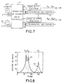
- FIG. 7 represents an example of a diagram making it possible to unwind the process steps.
- the method includes a step of eliminating the outputs associated with the transmitter that we just goniometre.
- the limiting parameter is the number of transmitters (M ⁇ N) whereas previously, the limiting parameter is the total number of multi-paths, ie ⁇ P m ⁇ N.
- the signal model used is that of expression (2).
- the method firstly comprises a step 40 of modeling the signals s m (t) by considering them as signals with finite impulse response of length L m . Under these conditions the delayed signal s m (t- ⁇ mp ) is the output of a filter of length L m , whose inputs are s m (t) up to s m (tL m +1), that is:
- x (t) By taking up expression (2) we then obtain the following expression of x (t):
- the method for example, directly implements, 41, the Souloumiac-Cardoso source separation method described in the aforementioned reference [1] on the observation vector y (t). Knowing that the signals s m (tk) are correlated, according to equations (46) (30) and the reference [2], the method identifies by transmitter several space-time signatures u mk verifying:
- the method then performs, 42, goniometry of an emitter on one of the vectors u ml ... u mK identified at the source separation output. Under these conditions the vector u mk is transformed into the following matrix (49): According to the relation (48) U mk is worth:
- the calculator Having carried out the goniometry on the vector u mk , the calculator will eliminate the vectors associated with the same emitter ie the u mj for j ⁇ k.
- This operation is carried out on all the vectors different from u mk , then the calculator goes to the next emitter by carrying out the goniometry step on one of the vectors u m'j not eliminated. After the direction finding the process repeats the elimination and all these operations continue until there are no more vectors u m'j .
- the incidences ⁇ mi of the P m paths are known for 1 ⁇ i ⁇ P m and the associated directing vectors a ( ⁇ mi ) can be deduced.
- This information is used to deduce propagation delays between journeys.
- the computer uses the outputs of the separation of spatio-temporal sources. From expression (2) we can write expression (46) of y (t) as follows:
- FIG. 8 represents the pseudo-spectra of MUSIC on the matrices R 1i (curve I) and R 2i (curve II) associated respectively with the first and the second transmitter.
- the maxima of these pseudo-spectra make it possible to determine the incidence ⁇ mp of the multi-paths of these transmitters.
Landscapes
- Engineering & Computer Science (AREA)
- General Physics & Mathematics (AREA)
- Radar, Positioning & Navigation (AREA)
- Remote Sensing (AREA)
- Physics & Mathematics (AREA)
- Radar Systems Or Details Thereof (AREA)
- Mobile Radio Communication Systems (AREA)
- Investigating Or Analyzing Materials By The Use Of Ultrasonic Waves (AREA)
- Noise Elimination (AREA)
- Variable-Direction Aerials And Aerial Arrays (AREA)
- Analysing Materials By The Use Of Radiation (AREA)
- Position Fixing By Use Of Radio Waves (AREA)
- Radio Relay Systems (AREA)
- Measurement Of Velocity Or Position Using Acoustic Or Ultrasonic Waves (AREA)
Abstract
Description
Les multi-trajets existent lorsqu'une onde émise par un émetteur se propage suivant plusieurs trajets en direction d'un récepteur ou d'un système de goniométrie. Les trajets multiples sont dus notamment à la présence d'obstacles présents entre un émetteur et un récepteur.
Le domaine de l'invention concerne notamment celui de la goniométrie de sources radio-électrique, le mot source désignant un émetteur. Le terme goniométrie signifie une « estimation d'incidences ».
Il est aussi celui du filtrage spatial qui a pour objectif de synthétiser une antenne dans la direction de chacun des émetteurs à partir d'un réseau d'antennes.
L'onde émise par l'émetteur peut se propager suivant plusieurs trajets selon un schéma donné à la figure 3. L'onde k(d) a un trajet direct d'incidence d et l'onde k(r) un trajet réfléchi d'incidence r. Les multi-trajets sont provoqués notamment par des obstacles 5 situés entre l'émetteur 6 et le système de réception 7. Au niveau de la station de réception, les différents trajets arrivent avec différentes incidences op où p correspond au pième trajet. Les multi-trajets suivent des chemins de propagation différents et sont donc reçus à des instants tmp différents.
Les N antennes du système de réception reçoivent le signal xn(t) où n est l'indice du capteur. A partir de ces N signaux xn(t) on construit le vecteur d'observation :

- a(mp) est le vecteur directeur du pième trajet du mième émetteur. Le vecteur a() est la réponse du réseau de N capteurs à une source d'incidence
- ρmp est le facteur d'atténuation du pième trajet du mième émetteur
- τmp est le retard du pième trajet du mième émetteur
- Pm est le nombre de multi-trajets du mième émetteur
- sm(t) est le signal émis par le mième émetteur
- b(t) est le vecteur bruit composé du bruit additif bn(t) (1≤n≤N) sur chacun des capteurs.
Ces techniques consistent à estimer les signaux sm(t-τmp) à partir du vecteur observation x(t) sans aucune connaissance de leurs propriétés temporelles. Ces techniques sont dites aveugles. La seule hypothèse est que les signaux sm(t-τmp) sont statistiquement indépendants pour un trajet p tel que 1≤p≤Pm et un émetteur m tel que 1≤m≤M. Sachant que la corrélation entre les signaux sm(t) et sm(t-τ) est égale à l'ordre 2 à la fonction d'autocorrélation rsm(τ)=E[sm(t) sm(t-τ)*] du signal sm(t), on en déduit que les multi-trajets d'un même émetteur de signal sm(t) sont dépendants car la fonction rsm(τ) est non nulle. Toutefois deux émetteurs différents m et m', de signaux respectifs sm(t) et sm'(t), sont statistiquement indépendants s'il vérifie la relation E[sm(t) sm'(t)*]=0, où E[.] est l'espérance mathématique. Dans ces conditions, ces techniques peuvent fonctionner lorsque l'onde se propage sous forme de monotrajet, lorsque P1=...=PM=1. Le vecteur observation x(t) s'exprime alors par:

Ces méthodes consistent à construire une matrice W de dimension (N x M), appelée séparateur, générant à chaque instant t un vecteur y(t) de dimension M qui correspond à une matrice diagonale et, à une matrice de permutation près, à une estimée du vecteur source s(t) des enveloppes des M signaux d'intérêt pour le récepteur. Cette problématique de séparation de sources peut être résumée par l'expression suivante de la sortie vectorielle désirée à l'instant t du séparateur linéaire W:










- une étape d'intercorrélation deux par deux des composantes uk(t) du vecteur signal s'(t) issu de l'étape de séparation des sources,
- une étape de recherche de la ou des valeurs des retards permettant d'obtenir une valeur maximale pour la fonction d'intercorrélation, rkk'(τ) = E[uk(t)uk'(t-τ)*],
- une étape de mémorisation des différents indices des trajets pour lesquels la fonction de corrélation est maximale.
- La figure 1 un système d'émission réception et la figure 2 un réseau de N capteurs,
- La figure 3 les trajets possibles des ondes émises pour un émetteur,
- La figure 4 une méthode de séparation de sources selon l'art antérieur,
- La figure 5 un schéma des différentes étapes d'une première méthode selon l'invention d'association de sources et la figure 6 l'algorithme de traitement associé,
- La figure 7 une deuxième variante avec séparation de sources spatio-temporelle,
- La figure 8 un exemple de spectre obtenu.

De même, pour ce mième émetteur on identifie les Pm signaux suivants :

Le procédé comporte par exemple les étapes suivantes :






- Les signaux uk(t) et uk'(t) sont corrélés (H1) : Vkk'(τ) > α(pfa)
- Les signaux uk(t) et uk'(t) sont décorrélés (H0) : Vkk'(τ) < α(pfa)


et
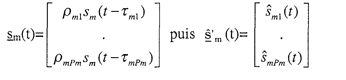

- Etape n°1 : Construction de Am= [ a(m1)....a(mPm)] à partir des incidences mi.
- Etape n°2 : Calcul du signal s m(t) à partir de l'expression (42).
- Etape n°3 : Pour chaque trajet effectuer les opérations suivantes
- Calcul du critère Cri i(δτ) de l'expression (43)
- Maximisation du critère Cri i(δτ) pour obtenir δτmi=τmi - τm1.





Où trace{Mat} désigne la trace de la matrice Mat. Pour une matrice Um'j quelconque le critère Cri(j) est normalisé entre 0 et 1. Lorsque la matrice Umj est associé à un vecteur u mj associé au même émetteur que u mk ce critère Cri(j) s'annule. Sachant que Πm et Umj sont estimées avec une certaine précision, on comparera Cri(j) à un seuil α proche de zéros (typiquement 0.1) pour décider si les vecteurs u mk et u m'j appartiennent au même émetteur : Cri(j) < α implique que u mk et u m'j sont associés au même émetteur et que m'=m. Ainsi pour identifier qu'un vecteur u m'j est associé au même émetteur que le vecteur u mk le calculateur effectue les opérations suivantes :
- Cri(j) < α ⇒ u mk et u m'j sont associés au même émetteur m'=m et élimination du vecteur u mj.
- Cri(j) > α ⇒ m'≠m.



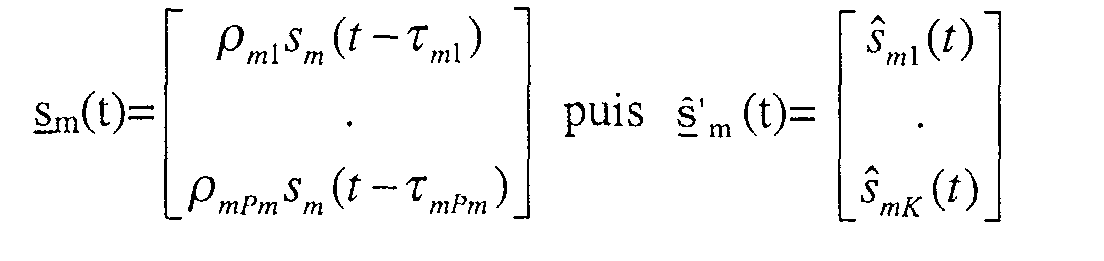

- Etape n°1 : Construction de Am=[a(m1)....a(mPm)] à partir des incidences mi.
- Etape n°2 : Calcul du signal s m(t) à partir de l'expression (57).
- Etape n°3 : Pour chaque trajet effectuer les opérations suivantes.
- Calcul du critère Cri i(δτ) de l'expression (58).
- Maximisation du critère Cri i(δτ) pour obtenir δτmi=τmi - τm1.
- 1ier émetteur (m=1) : composé de P1=2 trajets
tel que 11=60° 12=75° et le retard τ12=0 τ12=2 échantillons QPSK NRZ à 10 échantillons par symboles. - 2ieme émetteur (m=2) : composé de P1=2 trajets
tel que 21=150 et le retard τ21=0
Claims (11)
- Procédé d'estimation spatio-temporel d'un ou de plusieurs émetteurs à partir d'un réseau antennaire caractérisé en ce qu'il comporte au moins une étape de séparation des émetteurs et une étape de détermination des différents angles d'arrivée mi des pm multitrajets émis par chacun des émetteurs.
- Procédé selon la revendication 1 caractérisé en ce qu'il comporte au moins une étape de séparation des émetteurs afin d'obtenir les différents signaux s(t) reçus par le réseau d'antennes, une étape de regroupement des différents signaux par émetteur et une étape de détermination des différents angles mi des multitrajets par émetteur.
- Procédé selon la revendication 2 caractérisé en ce que l'étape de regroupement des différents signaux par émetteur comporte :une étape d'intercorrélation deux par deux des composantes uk(t) du vecteur signal s'(t) issu de l'étape de séparation des sources,une étape de recherche de la ou des valeurs des retards permettant d'obtenir une valeur maximale pour la fonction d'intercorrélation, rkk'(τ) = E[uk(t)uk'(t-τ)*],une étape de mémorisation des différents indices des trajets pour lesquels la fonction de corrélation est maximale.
- Procédé selon l'une des revendications 1 à 3 caractérisé en ce qu'il comporte une étape de détermination des temps de retard à partir des incidences mi, du signal s m(t) et et de la recherche du maximum du critère Cri i(δτ) pour obtenir δτmi=τmi - τm1, avec Crii(δτ)=E[sm(t)(i)sm(t- δτ)(1)*].
- Procédé selon la revendication 1 caractérisé en ce qu'il comporte une étape de séparation spatio-temporelle des différents émetteurs, avant de déterminer les angles d'arrivée mi.
- Procédé selon la revendication 5 caractérisé en ce que l'étape de séparation spatio-temporelle comporte une étape où, pour un émetteur donné, le signal sm(t) est retardé, assimilant ainsi le signal retardé à la sortie d'un filtre de longueur Lm dont les entrées sont sm(t) jusqu'à sm(t-τm), avant d'appliquer l'étape de séparation de sources.
- Procédé selon l'une des revendications 5 et 6 caractérisé en ce qu'il comporte une étape d'identification et d'élimination des sorties associées au même émetteur après avoir déterminé les angles mi.
- Procédé selon l'une des revendications 2 à 3 et 5 à 7 caractérisé en ce qu'il utilise une méthode de goniométrie haute résolution de type MUSIC, par interférométrie, etc.
- Application du procédé selon l'une des revendications 1 à 8 à la goniométrie de sources multitrajets.
- Application du procédé selon l'une des revendications 1 à 8 à la goniométrie de trajets avec P1=P2=...=Pm=1
- Dispositif d'estimation spatio-temporel d'un ensemble d'émetteurs qui émettent des ondes se propageant sous la forme de multitrajets dans un réseau de N capteurs caractérisé en ce qu'il comporte un calculateur adapté à mettre en oeuvre les étapes du procédé selon l'une des revendications 1 à 7.
Applications Claiming Priority (2)
| Application Number | Priority Date | Filing Date | Title |
|---|---|---|---|
| FR0105731 | 2001-04-27 | ||
| FR0105731A FR2824145B1 (fr) | 2001-04-27 | 2001-04-27 | Procede et dispositif d'estimation spatio-temporelle d'un ou plusieurs emetteurs |
Publications (2)
| Publication Number | Publication Date |
|---|---|
| EP1253435A1 true EP1253435A1 (fr) | 2002-10-30 |
| EP1253435B1 EP1253435B1 (fr) | 2009-12-02 |
Family
ID=8862797
Family Applications (1)
| Application Number | Title | Priority Date | Filing Date |
|---|---|---|---|
| EP02291003A Expired - Lifetime EP1253435B1 (fr) | 2001-04-27 | 2002-04-19 | Procédé et dispositif d'estimation spatio-temporelle d'un ou de plusieurs émetteurs |
Country Status (6)
| Country | Link |
|---|---|
| US (1) | US6744407B2 (fr) |
| EP (1) | EP1253435B1 (fr) |
| AT (1) | ATE450804T1 (fr) |
| CA (1) | CA2382313A1 (fr) |
| DE (1) | DE60234548D1 (fr) |
| FR (1) | FR2824145B1 (fr) |
Cited By (1)
| Publication number | Priority date | Publication date | Assignee | Title |
|---|---|---|---|---|
| CN114428225A (zh) * | 2022-04-06 | 2022-05-03 | 中国电子科技集团公司第二十九研究所 | 一种基于准匹配滤波的多辐射源到达角度测量方法及装置 |
Families Citing this family (11)
| Publication number | Priority date | Publication date | Assignee | Title |
|---|---|---|---|---|
| JP2002084217A (ja) * | 2000-09-08 | 2002-03-22 | Matsushita Electric Ind Co Ltd | 基地局装置および到来方向推定方法 |
| FR2853427B1 (fr) * | 2003-04-01 | 2005-06-17 | Thales Sa | Procede d'identification aveugle de melanges de sources aux ordres superieurs |
| CH697469B1 (de) * | 2004-05-06 | 2008-10-31 | Girsberger Elektronik Ag | Vorrichtung zur Erkennung der Betriebsart Senden eines Lawinenverschütteten-Suchgerà tes. |
| FR2872350B1 (fr) * | 2004-06-25 | 2006-12-22 | Thales Sa | Procede de goniometrie multi-parametres par separation de l'incidence et des parametres de nuisances |
| EP1846778B1 (fr) * | 2005-02-01 | 2008-10-29 | Thales | Procede de goniometrie en 1d ou 2d de sources diffuses |
| JP2009529699A (ja) * | 2006-03-01 | 2009-08-20 | ソフトマックス,インコーポレイテッド | 分離信号を生成するシステムおよび方法 |
| EP3151028B1 (fr) * | 2015-09-29 | 2018-11-14 | Rohde & Schwarz GmbH & Co. KG | Radiogoniomètre et procédé de radiogoniométrie, dans lequel un critère de qualité pour les signaux entrants est déterminé |
| US11143735B2 (en) * | 2018-12-21 | 2021-10-12 | Silicon Laboratories, Inc. | Pseudo-spectrum averaging for angle of arrival detection |
| US11635483B2 (en) | 2021-06-14 | 2023-04-25 | Silicon Laboratories Inc. | AoX multipath detection |
| FR3153474B1 (fr) * | 2023-09-21 | 2025-12-12 | Thales Sa | Procédé de détermination de la direction d’arrivée des trajets de signaux sur un réseau de N capteurs, programme d’ordinateur et dispositif associés |
| WO2025239808A1 (fr) * | 2024-05-16 | 2025-11-20 | Telefonaktiebolaget Lm Ericsson (Publ) | Système de séparation de signal brouilleur d'un signal utilisateur et procédé associé |
Family Cites Families (6)
| Publication number | Priority date | Publication date | Assignee | Title |
|---|---|---|---|---|
| FR2732490B1 (fr) | 1995-03-28 | 1997-04-25 | Thomson Csf | Procede de reception multicapteur d'une station de base d'un reseau de communication echangeant des donnees avec des mobiles, et dispositif pour sa mise en oeuvre |
| FR2735937B1 (fr) | 1995-06-23 | 1997-08-08 | Thomson Csf | Procede de tarage des chaines emission et reception des voies formees par une station de base d'un systeme de radiocommunication entre mobiles |
| EP0846378B1 (fr) | 1995-08-22 | 1999-10-06 | Thomson-Csf | Procede et dispositif de multiplexage/demultiplexage spatial de signaux radioelectriques pour systeme radio mobile sdma |
| FR2749733B1 (fr) | 1996-06-07 | 1998-11-27 | Thomson Csf | Procede et dispositif de gestion des transferts intercellulaires des communications dans un systeme de radiocommunication cellulaire |
| FR2764074B1 (fr) | 1997-06-03 | 1999-08-20 | Thomson Csf | Procede et dispositif de radiogoniometrie cooperative en transmission |
| FR2766320B1 (fr) | 1997-07-15 | 1999-10-15 | Thomson Csf | Procede et dispositif d'analyse des interferences dans un systeme de radiocommunication cellulaire |
-
2001
- 2001-04-27 FR FR0105731A patent/FR2824145B1/fr not_active Expired - Fee Related
-
2002
- 2002-04-19 AT AT02291003T patent/ATE450804T1/de not_active IP Right Cessation
- 2002-04-19 EP EP02291003A patent/EP1253435B1/fr not_active Expired - Lifetime
- 2002-04-19 DE DE60234548T patent/DE60234548D1/de not_active Expired - Lifetime
- 2002-04-24 US US10/128,259 patent/US6744407B2/en not_active Expired - Fee Related
- 2002-04-25 CA CA002382313A patent/CA2382313A1/fr not_active Abandoned
Non-Patent Citations (7)
| Title |
|---|
| CARDOSO J F ET AL: "BLIND BEAMFORMING FOR NON-GAUSSIAN SIGNALS", IEE PROCEEDINGS F. COMMUNICATIONS, RADAR & SIGNAL PROCESSING, INSTITUTION OF ELECTRICAL ENGINEERS. STEVENAGE, GB, vol. 140, no. 6, 1 December 1993 (1993-12-01), pages 362 - 370, XP000605067, ISSN: 0956-375X * |
| CHEVALIER P ET AL: "Behaviour of higher order blind source separation methods in the presence of cyclostationary correlated multipaths", HIGHER-ORDER STATISTICS, 1997., PROCEEDINGS OF THE IEEE SIGNAL PROCESSING WORKSHOP ON BANFF, ALTA., CANADA 21-23 JULY 1997, LOS ALAMITOS, CA, USA,IEEE COMPUT. SOC, US, 21 July 1997 (1997-07-21), pages 363 - 367, XP010239783, ISBN: 0-8186-8005-9 * |
| P. CHEVALIER; G. BENOIT; A. FERREOL: "Direction finding after blind identification of sources steering vectors: The Blind-Maxcor and Blind-MUSIC methods", PROC. EUSIPCO, September 1996 (1996-09-01) |
| PHD THESIS, November 1981 (1981-11-01) |
| SEE C-M S ET AL: "Estimating directions and times of arrival of multipath signals using a calibrated space-time antenna array", STATISTICAL SIGNAL AND ARRAY PROCESSING, 1998. PROCEEDINGS., NINTH IEEE SP WORKSHOP ON PORTLAND, OR, USA 14-16 SEPT. 1998, NEW YORK, NY, USA,IEEE, US, 14 September 1998 (1998-09-14), pages 364 - 367, XP010317903, ISBN: 0-7803-5010-3 * |
| VAN DER VEEN A-J ET AL: "SI-JADE: an algorithm for joint angle and delay estimation using shift-invariance properties", SIGNAL PROCESSING ADVANCES IN WIRELESS COMMUNICATIONS, FIRST IEEE SIGNAL PROCESSING WORKSHOP ON PARIS, FRANCE 16-18 APRIL 1997, NEW YORK, NY, USA,IEEE, US, 16 April 1997 (1997-04-16), pages 161 - 164, XP010251458, ISBN: 0-7803-3944-4 * |
| VANDERVEEN M C ET AL: "Joint angle and delay estimation (JADE) for signals in multipath environments", SIGNALS, SYSTEMS AND COMPUTERS, 1996. CONFERENCE RECORD OF THE THIRTIETH ASILOMAR CONFERENCE ON PACIFIC GROVE, CA, USA 3-6 NOV. 1996, LOS ALAMITOS, CA, USA,IEEE COMPUT. SOC, US, 3 November 1996 (1996-11-03), pages 1250 - 1254, XP010231347, ISBN: 0-8186-7646-9 * |
Cited By (2)
| Publication number | Priority date | Publication date | Assignee | Title |
|---|---|---|---|---|
| CN114428225A (zh) * | 2022-04-06 | 2022-05-03 | 中国电子科技集团公司第二十九研究所 | 一种基于准匹配滤波的多辐射源到达角度测量方法及装置 |
| CN114428225B (zh) * | 2022-04-06 | 2022-06-14 | 中国电子科技集团公司第二十九研究所 | 一种基于准匹配滤波的多辐射源到达角度测量方法及装置 |
Also Published As
| Publication number | Publication date |
|---|---|
| DE60234548D1 (de) | 2010-01-14 |
| FR2824145A1 (fr) | 2002-10-31 |
| CA2382313A1 (fr) | 2002-10-27 |
| US20030052820A1 (en) | 2003-03-20 |
| US6744407B2 (en) | 2004-06-01 |
| FR2824145B1 (fr) | 2005-04-15 |
| EP1253435B1 (fr) | 2009-12-02 |
| ATE450804T1 (de) | 2009-12-15 |
Similar Documents
| Publication | Publication Date | Title |
|---|---|---|
| EP2368133B1 (fr) | Procede de localisation par estimation multi-voies des tdoa et fdoa des multi-trajets d'une source avec ou sans aoa | |
| EP2428810B1 (fr) | Procédé de géo-localisation multi-émetteurs par traitement spatio-temporel | |
| EP2368129B1 (fr) | Procédé de determination des angles d'arrivée en azimut et en elevation de sources coherentes | |
| EP2100161B1 (fr) | Procede de traitement radar passif multivoies d'un signal d'opportunite en fm | |
| EP2579063B1 (fr) | Procédé et système de localisation d'interferences par sous-bande fréquentielle | |
| EP4172655A1 (fr) | Procede de detection de cible pour radar a penetration de sol et radar associe | |
| EP1253435B1 (fr) | Procédé et dispositif d'estimation spatio-temporelle d'un ou de plusieurs émetteurs | |
| EP0926510B1 (fr) | Procedé de localisation spatio-temporelle, de radio-mobiles en milieu urbain | |
| EP2612166B1 (fr) | Procédé et dispositif de localisation d'au moins un obstacle dans un réseau de communication, programme d'ordinateur correspondant | |
| FR2805614A1 (fr) | Procede de localisation de sources radioelectriques au moyen d'un radiogoniometre haute resolution deux voies | |
| EP1582888B1 (fr) | Procédé de localisation aveugle large bande d'un ou plusieurs émetteurs à partir d'un porteur défilant | |
| EP2523020A1 (fr) | Procédé et système de localisation d'interférences affectant un signal de radionavigation par satellite | |
| EP2517037B1 (fr) | Procede pour estimer le nombre de sources incidentes a un reseau de capteurs par estimation de la statistique du bruit | |
| Durofchalk et al. | Analysis of the ray-based blind deconvolution algorithm for shipping sources | |
| EP1291664B1 (fr) | Procédé et dispositif de radiogoniometrie cooperative en transmission | |
| US6807517B2 (en) | Method to estimate the parameters of a propagation channel | |
| EP1446898B1 (fr) | Recepteur de faisceaux incidents resultant de trajets multiples | |
| EP1815605B1 (fr) | Procédé pour caracteriser les émetteurs par association de parametres lies è une meme émetteur radio-électrique | |
| EP2857856B1 (fr) | Procédé de goniométrie avec un système ayant moins de voies de réception que de capteurs | |
| EP4528308A1 (fr) | Procédé de détermination de la direction d'arrivée des trajets de signaux sur un réseau de n capteurs, programme d'ordinateur et dispositif associés | |
| EP4528307A1 (fr) | Procédé de détermination de la direction d'arrivée des trajets de signaux ionosphériques hf sur un réseau de n capteurs, programme d'ordinateur et dispositif associés | |
| EP1292047B1 (fr) | Procédé et dispositif de détection de sources dans un système de communications | |
| WO2011058067A1 (fr) | Procede de goniometrie de multi-trajets avec un recepteur 2 voies | |
| FR2862137A1 (fr) | Procede de localisation d'un ou de plusieurs emetteurs |
Legal Events
| Date | Code | Title | Description |
|---|---|---|---|
| PUAI | Public reference made under article 153(3) epc to a published international application that has entered the european phase |
Free format text: ORIGINAL CODE: 0009012 |
|
| AK | Designated contracting states |
Kind code of ref document: A1 Designated state(s): AT BE CH CY DE DK ES FI FR GB GR IE IT LI LU MC NL PT SE TR |
|
| AX | Request for extension of the european patent |
Free format text: AL;LT;LV;MK;RO;SI |
|
| 17P | Request for examination filed |
Effective date: 20030411 |
|
| AKX | Designation fees paid |
Designated state(s): AT BE CH CY DE DK ES FI FR GB GR IE IT LI LU MC NL PT SE TR |
|
| 17Q | First examination report despatched |
Effective date: 20081029 |
|
| GRAP | Despatch of communication of intention to grant a patent |
Free format text: ORIGINAL CODE: EPIDOSNIGR1 |
|
| GRAS | Grant fee paid |
Free format text: ORIGINAL CODE: EPIDOSNIGR3 |
|
| RAP1 | Party data changed (applicant data changed or rights of an application transferred) |
Owner name: THALES |
|
| GRAA | (expected) grant |
Free format text: ORIGINAL CODE: 0009210 |
|
| AK | Designated contracting states |
Kind code of ref document: B1 Designated state(s): AT BE CH CY DE DK ES FI FR GB GR IE IT LI LU MC NL PT SE TR |
|
| REG | Reference to a national code |
Ref country code: GB Ref legal event code: FG4D Free format text: NOT ENGLISH |
|
| REG | Reference to a national code |
Ref country code: CH Ref legal event code: EP |
|
| REG | Reference to a national code |
Ref country code: IE Ref legal event code: FG4D |
|
| REF | Corresponds to: |
Ref document number: 60234548 Country of ref document: DE Date of ref document: 20100114 Kind code of ref document: P |
|
| REG | Reference to a national code |
Ref country code: SE Ref legal event code: TRGR |
|
| REG | Reference to a national code |
Ref country code: NL Ref legal event code: VDEP Effective date: 20091202 |
|
| PG25 | Lapsed in a contracting state [announced via postgrant information from national office to epo] |
Ref country code: CY Free format text: LAPSE BECAUSE OF FAILURE TO SUBMIT A TRANSLATION OF THE DESCRIPTION OR TO PAY THE FEE WITHIN THE PRESCRIBED TIME-LIMIT Effective date: 20091202 |
|
| PG25 | Lapsed in a contracting state [announced via postgrant information from national office to epo] |
Ref country code: AT Free format text: LAPSE BECAUSE OF FAILURE TO SUBMIT A TRANSLATION OF THE DESCRIPTION OR TO PAY THE FEE WITHIN THE PRESCRIBED TIME-LIMIT Effective date: 20091202 |
|
| REG | Reference to a national code |
Ref country code: IE Ref legal event code: FD4D |
|
| PG25 | Lapsed in a contracting state [announced via postgrant information from national office to epo] |
Ref country code: IE Free format text: LAPSE BECAUSE OF FAILURE TO SUBMIT A TRANSLATION OF THE DESCRIPTION OR TO PAY THE FEE WITHIN THE PRESCRIBED TIME-LIMIT Effective date: 20091202 Ref country code: PT Free format text: LAPSE BECAUSE OF FAILURE TO SUBMIT A TRANSLATION OF THE DESCRIPTION OR TO PAY THE FEE WITHIN THE PRESCRIBED TIME-LIMIT Effective date: 20100402 Ref country code: ES Free format text: LAPSE BECAUSE OF FAILURE TO SUBMIT A TRANSLATION OF THE DESCRIPTION OR TO PAY THE FEE WITHIN THE PRESCRIBED TIME-LIMIT Effective date: 20100313 Ref country code: NL Free format text: LAPSE BECAUSE OF FAILURE TO SUBMIT A TRANSLATION OF THE DESCRIPTION OR TO PAY THE FEE WITHIN THE PRESCRIBED TIME-LIMIT Effective date: 20091202 |
|
| PLBE | No opposition filed within time limit |
Free format text: ORIGINAL CODE: 0009261 |
|
| STAA | Information on the status of an ep patent application or granted ep patent |
Free format text: STATUS: NO OPPOSITION FILED WITHIN TIME LIMIT |
|
| PG25 | Lapsed in a contracting state [announced via postgrant information from national office to epo] |
Ref country code: GR Free format text: LAPSE BECAUSE OF FAILURE TO SUBMIT A TRANSLATION OF THE DESCRIPTION OR TO PAY THE FEE WITHIN THE PRESCRIBED TIME-LIMIT Effective date: 20100303 |
|
| BERE | Be: lapsed |
Owner name: THALES Effective date: 20100430 |
|
| 26N | No opposition filed |
Effective date: 20100903 |
|
| PG25 | Lapsed in a contracting state [announced via postgrant information from national office to epo] |
Ref country code: MC Free format text: LAPSE BECAUSE OF NON-PAYMENT OF DUE FEES Effective date: 20100430 |
|
| REG | Reference to a national code |
Ref country code: CH Ref legal event code: PL |
|
| PG25 | Lapsed in a contracting state [announced via postgrant information from national office to epo] |
Ref country code: DK Free format text: LAPSE BECAUSE OF FAILURE TO SUBMIT A TRANSLATION OF THE DESCRIPTION OR TO PAY THE FEE WITHIN THE PRESCRIBED TIME-LIMIT Effective date: 20091202 |
|
| PG25 | Lapsed in a contracting state [announced via postgrant information from national office to epo] |
Ref country code: CH Free format text: LAPSE BECAUSE OF NON-PAYMENT OF DUE FEES Effective date: 20100430 Ref country code: LI Free format text: LAPSE BECAUSE OF NON-PAYMENT OF DUE FEES Effective date: 20100430 |
|
| PG25 | Lapsed in a contracting state [announced via postgrant information from national office to epo] |
Ref country code: BE Free format text: LAPSE BECAUSE OF NON-PAYMENT OF DUE FEES Effective date: 20100430 |
|
| PG25 | Lapsed in a contracting state [announced via postgrant information from national office to epo] |
Ref country code: LU Free format text: LAPSE BECAUSE OF NON-PAYMENT OF DUE FEES Effective date: 20100419 |
|
| PG25 | Lapsed in a contracting state [announced via postgrant information from national office to epo] |
Ref country code: TR Free format text: LAPSE BECAUSE OF FAILURE TO SUBMIT A TRANSLATION OF THE DESCRIPTION OR TO PAY THE FEE WITHIN THE PRESCRIBED TIME-LIMIT Effective date: 20091202 |
|
| PGFP | Annual fee paid to national office [announced via postgrant information from national office to epo] |
Ref country code: IT Payment date: 20140411 Year of fee payment: 13 Ref country code: SE Payment date: 20140411 Year of fee payment: 13 |
|
| REG | Reference to a national code |
Ref country code: SE Ref legal event code: EUG |
|
| PG25 | Lapsed in a contracting state [announced via postgrant information from national office to epo] |
Ref country code: IT Free format text: LAPSE BECAUSE OF NON-PAYMENT OF DUE FEES Effective date: 20150419 |
|
| PG25 | Lapsed in a contracting state [announced via postgrant information from national office to epo] |
Ref country code: SE Free format text: LAPSE BECAUSE OF NON-PAYMENT OF DUE FEES Effective date: 20150420 |
|
| REG | Reference to a national code |
Ref country code: FR Ref legal event code: PLFP Year of fee payment: 15 |
|
| PGFP | Annual fee paid to national office [announced via postgrant information from national office to epo] |
Ref country code: FR Payment date: 20160323 Year of fee payment: 15 |
|
| PGFP | Annual fee paid to national office [announced via postgrant information from national office to epo] |
Ref country code: DE Payment date: 20160412 Year of fee payment: 15 Ref country code: FI Payment date: 20160411 Year of fee payment: 15 Ref country code: GB Payment date: 20160413 Year of fee payment: 15 |
|
| REG | Reference to a national code |
Ref country code: DE Ref legal event code: R119 Ref document number: 60234548 Country of ref document: DE |
|
| GBPC | Gb: european patent ceased through non-payment of renewal fee |
Effective date: 20170419 |
|
| REG | Reference to a national code |
Ref country code: FR Ref legal event code: ST Effective date: 20171229 |
|
| PG25 | Lapsed in a contracting state [announced via postgrant information from national office to epo] |
Ref country code: FI Free format text: LAPSE BECAUSE OF NON-PAYMENT OF DUE FEES Effective date: 20170419 Ref country code: DE Free format text: LAPSE BECAUSE OF NON-PAYMENT OF DUE FEES Effective date: 20171103 Ref country code: FR Free format text: LAPSE BECAUSE OF NON-PAYMENT OF DUE FEES Effective date: 20170502 |
|
| PG25 | Lapsed in a contracting state [announced via postgrant information from national office to epo] |
Ref country code: GB Free format text: LAPSE BECAUSE OF NON-PAYMENT OF DUE FEES Effective date: 20170419 |