EP1253254A2 - Pumped trap and method of installing same - Google Patents
Pumped trap and method of installing same Download PDFInfo
- Publication number
- EP1253254A2 EP1253254A2 EP02250152A EP02250152A EP1253254A2 EP 1253254 A2 EP1253254 A2 EP 1253254A2 EP 02250152 A EP02250152 A EP 02250152A EP 02250152 A EP02250152 A EP 02250152A EP 1253254 A2 EP1253254 A2 EP 1253254A2
- Authority
- EP
- European Patent Office
- Prior art keywords
- trap
- sump
- pumped
- screed
- floor
- Prior art date
- Legal status (The legal status is an assumption and is not a legal conclusion. Google has not performed a legal analysis and makes no representation as to the accuracy of the status listed.)
- Granted
Links
Images



Classifications
-
- E—FIXED CONSTRUCTIONS
- E03—WATER SUPPLY; SEWERAGE
- E03C—DOMESTIC PLUMBING INSTALLATIONS FOR FRESH WATER OR WASTE WATER; SINKS
- E03C1/00—Domestic plumbing installations for fresh water or waste water; Sinks
- E03C1/12—Plumbing installations for waste water; Basins or fountains connected thereto; Sinks
- E03C1/28—Odour seals
-
- E—FIXED CONSTRUCTIONS
- E03—WATER SUPPLY; SEWERAGE
- E03F—SEWERS; CESSPOOLS
- E03F5/00—Sewerage structures
- E03F5/04—Gullies inlets, road sinks, floor drains with or without odour seals or sediment traps
- E03F5/0407—Floor drains for indoor use
-
- E—FIXED CONSTRUCTIONS
- E03—WATER SUPPLY; SEWERAGE
- E03F—SEWERS; CESSPOOLS
- E03F5/00—Sewerage structures
- E03F5/04—Gullies inlets, road sinks, floor drains with or without odour seals or sediment traps
- E03F2005/0416—Gullies inlets, road sinks, floor drains with or without odour seals or sediment traps with an odour seal
-
- E—FIXED CONSTRUCTIONS
- E03—WATER SUPPLY; SEWERAGE
- E03F—SEWERS; CESSPOOLS
- E03F5/00—Sewerage structures
- E03F5/04—Gullies inlets, road sinks, floor drains with or without odour seals or sediment traps
- E03F2005/0416—Gullies inlets, road sinks, floor drains with or without odour seals or sediment traps with an odour seal
- E03F2005/0417—Gullies inlets, road sinks, floor drains with or without odour seals or sediment traps with an odour seal in the form of a valve
Definitions
- This invention relates to a pumped trap, in particular for fixing to a screed covered floor and to which a water resistant floor covering material can be clamped, and to a method of installing such a pumped trap.
- This type of flooring is especially useful in bathrooms for the disabled, invalid or infirm who are largely unable to negotiate stepping into and out of a bath or shower tray.
- a shower chair or wheelchair By having a water resistant floor covering laid in the bathroom, a shower chair or wheelchair can simply be placed beneath the shower head, and showering can commence without being overly concerned with splash or spray.
- the water resistant floor covering is provided with a fall that acts to channel the run-off water to a drain formed in the flooring.
- a problem associated with the installation of a seamless water resistant floor covering occurs when attempting to accommodate a suitable trap for drainage within the existing floor.
- a trap requires a relatively significant depth of floor to enable installation, and an opening has to be formed in the floor in which the trap can be positioned.
- the formation of an opening can often be troublesome, especially when the floor is concrete. If the floor is screed covered, the opening has to be formed in both the screed and the concrete floor.
- the former has to be suitably supported and its edges have to be coplanar with the rest of the floor to provide a level-entry type access.
- the use of a former increases costs and its installation involves it being recessed into the floor, which is troublesome with any type of flooring. If a screed covered concrete floor is present, screed has to be removed and then re-formed around the former.
- the present invention seeks to overcome the problem of installing a trap in or on a screed covered concrete floor.
- a pumped trap for fixing to a floor which includes a screed covering and to which a water resistant floor covering material can be attached, the trap comprising a sump, a waste water inlet through which waste water enters the sump, a waste water outlet, a pump for drawing at least a portion of the said waste water from the sump through the waste water outlet, means for securing the floor covering material to the trap, and one or more fixing elements by which the trap, in use, can be secured to the floor.
- a pumped trap in accordance with the first aspect of the present invention in combination with a floor covering material, the floor covering material being cold weldable to produce a seamless and water resistant covering.
- a pumped trap as claimed in any one of the preceding claims in a floor having a screed covering comprising the steps of:
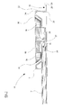
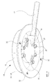
- a pumped trap 10 which is typically injection moulded from plastics material, is shown therein and comprises a sump 12, a waste water inlet 14, a waste water outlet 16, a pump (not shown), means for securing a water resistant floor covering material to the trap 10, and a fixing element 20.
- the sump 12 has a stepped profile which includes a skirt 22 that extends from the top edge 24 of the stepped profile to a level which is below the internal bottom surface 26 of the sump 12.
- the fixing element 20 is in the form of an annular flange 28 which is integrally formed on the bottom edge 30 of the skirt 22 and which extends outwardly at a level which is also below the internal bottom surface 26 of the sump 12.
- the annular flange 28 includes one or more openings 32 through which fixing, typically screw-threaded, devices 29 (shown in Figure 5) can be inserted.
- the sump 12 may also include one or more supporting elements 33 (shown in Figure 4) formed on or adjacent to the bottom surface 26 of the sump 12.
- the supporting elements 33 in use contact a supporting surface on which the trap 10 is mounted and aid in maintaining the structural integrity of the trap 10 when subjected to a downward force, such as that imparted by a person standing on the trap 10.
- the waste water outlet 16 is, typically integrally, formed in a side of the sump 12. This enables the depth of the sump 12 to be reduced.
- the waste water outlet 16 has an opening 34 (shown in Figure 3) therethrough and is dimensioned to be engagable with a discharge pipe 17, typically as an interference fit.
- a suitable adhesive may be used to secure the discharge pipe 17 to the waste water outlet 16.
- the discharge pipe 17 leads to the pump and may be flexible to aid installation.
- the securing means is typically in the form of a clamp element 18 which, in use, seats on a horizontal surface 36 of one of the steps of the stepped profile of the sump 12.
- the horizontal surface 36 is above the bottom surface 26 of the sump 12.
- the clamp element 18 is annular and has an upwardly inclined peripheral edge 38 which lies in parallel or substantially in parallel with the inner surface of the skirt 22 of the sump 12.
- the clamp element 18 also includes an opening 40 which forms part of the waste water inlet 14, and apertures 42 through which fastening, typically screw-threaded, devices 44 can be used to mechanically secure the clamp element 18 with the sump 12.
- the securing means could take the form of a suitable adhesive instead of the clamp element 18.
- the clamp element 18 tends to provide a more positive fixing.
- the pumped trap 10 further includes a removable cap 46 which is received within the clamp element 18 and the sump 12 so that the internal bottom surface 26 of the sump 12 is covered or substantially covered.
- the cap 46 includes a plurality of apertures 48 which, along with the opening 40 of the clamp element 18, serve to define the waste water inlet 14.
- the cap 46 also includes one or more apertures 50 through which respective fastening, typically screw-threaded, device 52 can be inserted to secure the cap 46 to the sump 12.
- the trap 10 To install the pumped trap 10 on or in a screed covered concrete floor, it is first decided where the trap 10 should be positioned. The screed at, and in the vicinity of, this position is then removed to a depth sufficient to receive the trap 10 to a level which is below the top surface 54 (see Figure 5) of the pre-existing screed covering 56. Typically, this will entail removing the screed 56 to the level of the concrete floor 58 on which the screed 56 is laid. However, if the screed covering 56 is of insufficient depth, a recess (not shown) may also have to be formed in the concrete of the concrete floor 58.
- the trap 10 is then positioned within the generated opening and the fixing devices are inserted through the openings 32 in the fixing element 20 and into the concrete floor or the material supporting the trap 10, thereby fixing the trap 10 in place.
- the discharge pipe connected to the waste water outlet 18, is also positioned within the opening generated by the removed screed, and is connected to the pump which is typically at a position remote from the trap 10.
- the screed covering, indicated at 60, is then re-formed in the opening. During the re-forming, a fall is included towards the trap 10.
- Stiff plastics water resistant material (not shown), typically being for example AltroTM, can then be laid over the screed covered floor.
- the water resistant material is mechanically clamped between the sump 12 and the clamp element 18 by use of the clamp element's fastening devices 44, and cold welded around the edges of the existing floor to create a seamless covering.
- the pump of the trap 10 operates to draw at least a portion of waste water, which enters the sump 12 through the waste water inlet 14, through the opening 34 of the waste water outlet 16 and along the discharge pipe 17 to a drain (not shown).
- the pump or the discharge pipe 17 typically includes a non-return valve (not shown) to prevent odours backing up through the waste water outlet 16, and the operation of the pump is linked to the operation of, for example, a shower which is to be used in conjunction with the water resistant floor covering.
- the end of the waste water outlet 16 which opens into the sump 12 may also include a partitioning element (not shown), which opens into the sump 12 at a level which is below a level of waste water held in the sump 12. This also aids in the prevention of odours.
- the fixing element 20 could be formed at a position which is at the top edge 24 of the sump 12 and/or intermediate the top edge 24 and the bottom internal surface 26.
- one or more suitable supporting elements such as a spacer, may be required between the fixing element 20 and the floor to provide stability.
- the supporting elements 33 could be removed, thereby enabling the bottom surface 26 of the sump 12 to be formed coplanar or substantially coplanar with the fixing element 20.
- the fixing element is not limited to an annular flange 28.
- the fixing element could also be formed projecting from the external bottom surface 27 of the sump 12, and may not require fixing devices as the re-forming of the screed could be used to cover the fixing element and thereby hold the pumped trap in place.
- a pumped trap can therefore be provided which, by the shallow depth of its sump, can be installed within the level of screed covering a concrete floor, and which can be fixed in place at a level which is at or below the level of the internal bottom surface of its sump. It is also possible to generate the fall towards the installed trap without the need for a former.
Landscapes
- Engineering & Computer Science (AREA)
- Health & Medical Sciences (AREA)
- Life Sciences & Earth Sciences (AREA)
- Hydrology & Water Resources (AREA)
- Public Health (AREA)
- Water Supply & Treatment (AREA)
- Environmental & Geological Engineering (AREA)
- Sink And Installation For Waste Water (AREA)
- Electrical Discharge Machining, Electrochemical Machining, And Combined Machining (AREA)
- Structures Of Non-Positive Displacement Pumps (AREA)
- Devices For Blowing Cold Air, Devices For Blowing Warm Air, And Means For Preventing Water Condensation In Air Conditioning Units (AREA)
Abstract
Description
Claims (14)
- A pumped trap for fixing to a floor which includes a screed covering and to which a water resistant floor covering material can be attached, the trap (10) comprising a sump (12), a waste water inlet (14) through which waste water enters the sump (12), a waste water outlet (16), a pump for drawing at least a portion of the said waste water from the sump (12) through the waste water outlet (16), means for securing the floor covering material to the trap (10), and one or more fixing elements (20) by which the trap (10), in use, can be secured to the floor.
- A pumped trap as claimed in claim 1, wherein the fixing element(s) (20) is/are at a level which is at or below a level of the internal bottom surface (26) of the sump (12).
- A pumped trap as claimed in claim 1 or claim 2, wherein the one or more fixing elements (20) is/are integrally formed as part of the sump (12).
- A pumped trap according to any one of the preceding claims, wherein the securing means is in the form of a clamp element (18) by which the floor covering material can be clamped to the trap (10).
- A pumped trap as claimed in claim 4, wherein the clamp element (18), in use, is secured to the sump (12).
- A pumped trap as claimed in any one of the preceding claims, wherein the waste water outlet (16) is integrally formed as part of the sump (12).
- A pumped trap as claimed in any one of the preceding claims, further comprising a removable cap (46) which substantially covers the sump (12).
- A pumped trap as claimed in claim 7, wherein the removable cap (46) is, in use, secured to the sump (12).
- A pumped trap according to any one of the preceding claims in combination with a floor covering material, the floor covering material being cold weldable to produce a seamless and water resistant covering.
- A method for installing a pumped trap as claimed in any one of the preceding claims in a floor having a screed covering, the method comprising the steps of:a) removing screed (56) to a depth sufficient to receive the pumped trap (10),b) installing the pumped trap (10) in the opening created by the removal of the screed (56) in step (a), andc) re-forming the screed covering (60).
- A method as claimed in claim 10, wherein the depth of screed (56) removed in step (a) is sufficient to receive the trap (10) to a level which is below the top surface (54) of the pre-existing screed covering (56).
- A method as claimed in claim 11, further comprising a step (d) between steps (a) and (b) of forming a recess in the floor below the screed (56) to enable the pumped trap (10) to be received to said level.
- A method as claimed in claim in any of claims 10 to 12, wherein the screed (60) is re-formed in step (c) to include a fall towards the trap (10).
- A method as claimed in any one of claims 10 to 13, further comprising a step (e) subsequent to step (c) of laying a water resistant floor covering material over the screed (56, 60) and securing it to the pumped trap (10) via the securing means.
Applications Claiming Priority (2)
| Application Number | Priority Date | Filing Date | Title |
|---|---|---|---|
| GB0110096A GB2374876B (en) | 2001-04-25 | 2001-04-25 | Pumped trap and method of installing same |
| GB0110096 | 2001-04-25 |
Publications (3)
| Publication Number | Publication Date |
|---|---|
| EP1253254A2 true EP1253254A2 (en) | 2002-10-30 |
| EP1253254A3 EP1253254A3 (en) | 2004-02-04 |
| EP1253254B1 EP1253254B1 (en) | 2009-08-26 |
Family
ID=9913405
Family Applications (1)
| Application Number | Title | Priority Date | Filing Date |
|---|---|---|---|
| EP02250152A Expired - Lifetime EP1253254B1 (en) | 2001-04-25 | 2002-01-10 | Method of installing a trap with a pump |
Country Status (6)
| Country | Link |
|---|---|
| EP (1) | EP1253254B1 (en) |
| AT (1) | ATE441004T1 (en) |
| DE (1) | DE60233457D1 (en) |
| ES (1) | ES2330308T3 (en) |
| GB (1) | GB2374876B (en) |
| HK (1) | HK1048652B (en) |
Cited By (5)
| Publication number | Priority date | Publication date | Assignee | Title |
|---|---|---|---|---|
| WO2005059259A1 (en) * | 2003-12-08 | 2005-06-30 | Xl Pumps Limited | Shower drainage |
| EP1785534A1 (en) * | 2005-11-15 | 2007-05-16 | VIEGA GmbH & Co. KG. | Floor drain |
| FR2905958A1 (en) * | 2006-09-19 | 2008-03-21 | Gerard Ginguene | Collector less shower`s column for bathroom of e.g. apartments, has sump pump for rising level of waste water above ground for passing waste water to evacuation network, and control unit prevents entry of water when water level is very high |
| GB2445612A (en) * | 2007-01-10 | 2008-07-16 | Terence Luther Cundick | Shower tray with integral pump |
| EP3272954A1 (en) * | 2016-07-22 | 2018-01-24 | Geberit International AG | Drain assembly |
Families Citing this family (3)
| Publication number | Priority date | Publication date | Assignee | Title |
|---|---|---|---|---|
| GB2431936A (en) * | 2005-11-04 | 2007-05-09 | Dlp Ltd | Method and apparatus for freely positioning a shower drain unit |
| GB2449265A (en) * | 2007-05-15 | 2008-11-19 | Waterworld Solutions Ltd | Pumped drainage system |
| US9790693B2 (en) | 2015-11-30 | 2017-10-17 | Bart Allen Wilde | Screed guide drain adaptor |
Family Cites Families (2)
| Publication number | Priority date | Publication date | Assignee | Title |
|---|---|---|---|---|
| DE3627807A1 (en) * | 1986-08-16 | 1988-02-25 | Dallmer Gmbh & Co | Discharge fitting for a tiled floor of a sanitary shower |
| SE507492C2 (en) * | 1996-10-30 | 1998-06-15 | Split Vision Dev Ab | Floor well with duct means for ventilation |
-
2001
- 2001-04-25 GB GB0110096A patent/GB2374876B/en not_active Expired - Lifetime
-
2002
- 2002-01-10 EP EP02250152A patent/EP1253254B1/en not_active Expired - Lifetime
- 2002-01-10 AT AT02250152T patent/ATE441004T1/en not_active IP Right Cessation
- 2002-01-10 DE DE60233457T patent/DE60233457D1/en not_active Expired - Lifetime
- 2002-01-10 ES ES02250152T patent/ES2330308T3/en not_active Expired - Lifetime
-
2003
- 2003-01-24 HK HK03100652.6A patent/HK1048652B/en not_active IP Right Cessation
Cited By (6)
| Publication number | Priority date | Publication date | Assignee | Title |
|---|---|---|---|---|
| WO2005059259A1 (en) * | 2003-12-08 | 2005-06-30 | Xl Pumps Limited | Shower drainage |
| EP1785534A1 (en) * | 2005-11-15 | 2007-05-16 | VIEGA GmbH & Co. KG. | Floor drain |
| FR2905958A1 (en) * | 2006-09-19 | 2008-03-21 | Gerard Ginguene | Collector less shower`s column for bathroom of e.g. apartments, has sump pump for rising level of waste water above ground for passing waste water to evacuation network, and control unit prevents entry of water when water level is very high |
| GB2445612A (en) * | 2007-01-10 | 2008-07-16 | Terence Luther Cundick | Shower tray with integral pump |
| GB2445612B (en) * | 2007-01-10 | 2011-05-11 | Terence Luther Cundick | Shower tray with integral pump |
| EP3272954A1 (en) * | 2016-07-22 | 2018-01-24 | Geberit International AG | Drain assembly |
Also Published As
| Publication number | Publication date |
|---|---|
| GB0110096D0 (en) | 2001-06-20 |
| DE60233457D1 (en) | 2009-10-08 |
| ES2330308T3 (en) | 2009-12-09 |
| EP1253254B1 (en) | 2009-08-26 |
| GB2374876B (en) | 2004-05-26 |
| HK1048652A1 (en) | 2003-04-11 |
| HK1048652B (en) | 2004-12-03 |
| ATE441004T1 (en) | 2009-09-15 |
| EP1253254A3 (en) | 2004-02-04 |
| GB2374876A (en) | 2002-10-30 |
Similar Documents
| Publication | Publication Date | Title |
|---|---|---|
| EP1212970B1 (en) | Shower tray | |
| US5299330A (en) | Easy-access shower base assembly | |
| EP1222339B1 (en) | Building construction with outlet and method therefor | |
| US8347426B2 (en) | Shower device level with the surrounding ground | |
| GB2270836A (en) | Shower tray | |
| EP1253254A2 (en) | Pumped trap and method of installing same | |
| WO2007028936A1 (en) | Flexible-wet-floor drain having tiling adaptor | |
| EP1243709B1 (en) | Former | |
| US7621002B1 (en) | System and method for controlling, draining, removing, and disposing of liquids and light solids | |
| GB2276541A (en) | Apparatus for use in removing water from a shower tray | |
| US20070277306A1 (en) | Shower Drainage | |
| HK1046834A1 (en) | Shower tray | |
| US8578522B1 (en) | System and method for controlling, draining, removing, and disposing of liquids and light solids | |
| KR200220668Y1 (en) | Sleeve for Drain Trap | |
| KR200206787Y1 (en) | Drain Trap Having Attachable Member For Straining Dirt | |
| AU2007203019B2 (en) | Floor Waste Assembly | |
| GB2431936A (en) | Method and apparatus for freely positioning a shower drain unit | |
| EP1236429A1 (en) | Kit consisting of a structure, a water resistant floor covering material and a finishing element | |
| JPH11148158A (en) | Bathtub with wash place | |
| KR200352198Y1 (en) | Tranch with draining structure | |
| JPH0716781Y2 (en) | Bathroom drain | |
| EP3971353A1 (en) | Floor gully assembly comprising floor gully and water trap | |
| JPH0726462Y2 (en) | Bathroom floor drain tray | |
| AU2023208108A1 (en) | Drain apparatus | |
| KR200235659Y1 (en) | Drain Trap Cover |
Legal Events
| Date | Code | Title | Description |
|---|---|---|---|
| PUAI | Public reference made under article 153(3) epc to a published international application that has entered the european phase |
Free format text: ORIGINAL CODE: 0009012 |
|
| AK | Designated contracting states |
Kind code of ref document: A2 Designated state(s): AT BE CH CY DE DK ES FI FR GB GR IE IT LI LU MC NL PT SE TR |
|
| AX | Request for extension of the european patent |
Free format text: AL;LT;LV;MK;RO;SI |
|
| PUAL | Search report despatched |
Free format text: ORIGINAL CODE: 0009013 |
|
| AK | Designated contracting states |
Kind code of ref document: A3 Designated state(s): AT BE CH CY DE DK ES FI FR GB GR IE IT LI LU MC NL PT SE TR |
|
| AX | Request for extension of the european patent |
Extension state: AL LT LV MK RO SI |
|
| RAP1 | Party data changed (applicant data changed or rights of an application transferred) |
Owner name: DLP LIMITED |
|
| 17P | Request for examination filed |
Effective date: 20040712 |
|
| AKX | Designation fees paid |
Designated state(s): AT BE CH CY DE DK ES FI FR GR IE IT LI LU MC NL PT SE TR |
|
| 17Q | First examination report despatched |
Effective date: 20070102 |
|
| GRAP | Despatch of communication of intention to grant a patent |
Free format text: ORIGINAL CODE: EPIDOSNIGR1 |
|
| RTI1 | Title (correction) |
Free format text: METHOD OF INSTALLING A TRAP WITH A PUMP |
|
| GRAS | Grant fee paid |
Free format text: ORIGINAL CODE: EPIDOSNIGR3 |
|
| GRAA | (expected) grant |
Free format text: ORIGINAL CODE: 0009210 |
|
| AK | Designated contracting states |
Kind code of ref document: B1 Designated state(s): AT BE CH CY DE DK ES FI FR GR IE IT LI LU MC NL PT SE TR |
|
| REG | Reference to a national code |
Ref country code: CH Ref legal event code: EP |
|
| REG | Reference to a national code |
Ref country code: IE Ref legal event code: FG4D |
|
| REF | Corresponds to: |
Ref document number: 60233457 Country of ref document: DE Date of ref document: 20091008 Kind code of ref document: P |
|
| REG | Reference to a national code |
Ref country code: ES Ref legal event code: FG2A Ref document number: 2330308 Country of ref document: ES Kind code of ref document: T3 |
|
| PG25 | Lapsed in a contracting state [announced via postgrant information from national office to epo] |
Ref country code: AT Free format text: LAPSE BECAUSE OF FAILURE TO SUBMIT A TRANSLATION OF THE DESCRIPTION OR TO PAY THE FEE WITHIN THE PRESCRIBED TIME-LIMIT Effective date: 20090826 Ref country code: FI Free format text: LAPSE BECAUSE OF FAILURE TO SUBMIT A TRANSLATION OF THE DESCRIPTION OR TO PAY THE FEE WITHIN THE PRESCRIBED TIME-LIMIT Effective date: 20090826 Ref country code: SE Free format text: LAPSE BECAUSE OF FAILURE TO SUBMIT A TRANSLATION OF THE DESCRIPTION OR TO PAY THE FEE WITHIN THE PRESCRIBED TIME-LIMIT Effective date: 20090826 |
|
| NLV1 | Nl: lapsed or annulled due to failure to fulfill the requirements of art. 29p and 29m of the patents act | ||
| PG25 | Lapsed in a contracting state [announced via postgrant information from national office to epo] |
Ref country code: NL Free format text: LAPSE BECAUSE OF FAILURE TO SUBMIT A TRANSLATION OF THE DESCRIPTION OR TO PAY THE FEE WITHIN THE PRESCRIBED TIME-LIMIT Effective date: 20090826 |
|
| PG25 | Lapsed in a contracting state [announced via postgrant information from national office to epo] |
Ref country code: PT Free format text: LAPSE BECAUSE OF FAILURE TO SUBMIT A TRANSLATION OF THE DESCRIPTION OR TO PAY THE FEE WITHIN THE PRESCRIBED TIME-LIMIT Effective date: 20091228 Ref country code: CY Free format text: LAPSE BECAUSE OF FAILURE TO SUBMIT A TRANSLATION OF THE DESCRIPTION OR TO PAY THE FEE WITHIN THE PRESCRIBED TIME-LIMIT Effective date: 20090826 |
|
| PG25 | Lapsed in a contracting state [announced via postgrant information from national office to epo] |
Ref country code: DK Free format text: LAPSE BECAUSE OF FAILURE TO SUBMIT A TRANSLATION OF THE DESCRIPTION OR TO PAY THE FEE WITHIN THE PRESCRIBED TIME-LIMIT Effective date: 20090826 |
|
| PLBE | No opposition filed within time limit |
Free format text: ORIGINAL CODE: 0009261 |
|
| STAA | Information on the status of an ep patent application or granted ep patent |
Free format text: STATUS: NO OPPOSITION FILED WITHIN TIME LIMIT |
|
| 26N | No opposition filed |
Effective date: 20100527 |
|
| PG25 | Lapsed in a contracting state [announced via postgrant information from national office to epo] |
Ref country code: MC Free format text: LAPSE BECAUSE OF NON-PAYMENT OF DUE FEES Effective date: 20100131 |
|
| REG | Reference to a national code |
Ref country code: CH Ref legal event code: PL |
|
| PG25 | Lapsed in a contracting state [announced via postgrant information from national office to epo] |
Ref country code: LI Free format text: LAPSE BECAUSE OF NON-PAYMENT OF DUE FEES Effective date: 20100131 Ref country code: GR Free format text: LAPSE BECAUSE OF FAILURE TO SUBMIT A TRANSLATION OF THE DESCRIPTION OR TO PAY THE FEE WITHIN THE PRESCRIBED TIME-LIMIT Effective date: 20091127 Ref country code: CH Free format text: LAPSE BECAUSE OF NON-PAYMENT OF DUE FEES Effective date: 20100131 |
|
| PG25 | Lapsed in a contracting state [announced via postgrant information from national office to epo] |
Ref country code: LU Free format text: LAPSE BECAUSE OF NON-PAYMENT OF DUE FEES Effective date: 20100110 |
|
| PG25 | Lapsed in a contracting state [announced via postgrant information from national office to epo] |
Ref country code: TR Free format text: LAPSE BECAUSE OF FAILURE TO SUBMIT A TRANSLATION OF THE DESCRIPTION OR TO PAY THE FEE WITHIN THE PRESCRIBED TIME-LIMIT Effective date: 20090826 |
|
| REG | Reference to a national code |
Ref country code: FR Ref legal event code: PLFP Year of fee payment: 15 |
|
| PGFP | Annual fee paid to national office [announced via postgrant information from national office to epo] |
Ref country code: ES Payment date: 20160112 Year of fee payment: 15 Ref country code: DE Payment date: 20160120 Year of fee payment: 15 Ref country code: IT Payment date: 20160127 Year of fee payment: 15 |
|
| REG | Reference to a national code |
Ref country code: FR Ref legal event code: PLFP Year of fee payment: 16 |
|
| REG | Reference to a national code |
Ref country code: DE Ref legal event code: R119 Ref document number: 60233457 Country of ref document: DE |
|
| PG25 | Lapsed in a contracting state [announced via postgrant information from national office to epo] |
Ref country code: DE Free format text: LAPSE BECAUSE OF NON-PAYMENT OF DUE FEES Effective date: 20170801 |
|
| REG | Reference to a national code |
Ref country code: FR Ref legal event code: PLFP Year of fee payment: 17 |
|
| PG25 | Lapsed in a contracting state [announced via postgrant information from national office to epo] |
Ref country code: IT Free format text: LAPSE BECAUSE OF NON-PAYMENT OF DUE FEES Effective date: 20170110 |
|
| PG25 | Lapsed in a contracting state [announced via postgrant information from national office to epo] |
Ref country code: ES Free format text: LAPSE BECAUSE OF NON-PAYMENT OF DUE FEES Effective date: 20170111 |
|
| REG | Reference to a national code |
Ref country code: ES Ref legal event code: FD2A Effective date: 20181114 |
|
| PGFP | Annual fee paid to national office [announced via postgrant information from national office to epo] |
Ref country code: FR Payment date: 20210121 Year of fee payment: 20 Ref country code: IE Payment date: 20210105 Year of fee payment: 20 |
|
| PGFP | Annual fee paid to national office [announced via postgrant information from national office to epo] |
Ref country code: BE Payment date: 20210120 Year of fee payment: 20 |
|
| REG | Reference to a national code |
Ref country code: BE Ref legal event code: MK Effective date: 20220110 |
|
| REG | Reference to a national code |
Ref country code: IE Ref legal event code: MK9A |
|
| PG25 | Lapsed in a contracting state [announced via postgrant information from national office to epo] |
Ref country code: IE Free format text: LAPSE BECAUSE OF EXPIRATION OF PROTECTION Effective date: 20220110 |