EP1253250A2 - Blower having fan oriented perpendicular to discharge nozzle - Google Patents
Blower having fan oriented perpendicular to discharge nozzle Download PDFInfo
- Publication number
- EP1253250A2 EP1253250A2 EP02253003A EP02253003A EP1253250A2 EP 1253250 A2 EP1253250 A2 EP 1253250A2 EP 02253003 A EP02253003 A EP 02253003A EP 02253003 A EP02253003 A EP 02253003A EP 1253250 A2 EP1253250 A2 EP 1253250A2
- Authority
- EP
- European Patent Office
- Prior art keywords
- housing
- blower
- discharge port
- airflow
- fan
- Prior art date
- Legal status (The legal status is an assumption and is not a legal conclusion. Google has not performed a legal analysis and makes no representation as to the accuracy of the status listed.)
- Granted
Links
Images

Classifications
-
- E—FIXED CONSTRUCTIONS
- E01—CONSTRUCTION OF ROADS, RAILWAYS, OR BRIDGES
- E01H—STREET CLEANING; CLEANING OF PERMANENT WAYS; CLEANING BEACHES; DISPERSING OR PREVENTING FOG IN GENERAL CLEANING STREET OR RAILWAY FURNITURE OR TUNNEL WALLS
- E01H1/00—Removing undesirable matter from roads or like surfaces, with or without moistening of the surface
- E01H1/08—Pneumatically dislodging or taking-up undesirable matter or small objects; Drying by heat only or by streams of gas; Cleaning by projecting abrasive particles
- E01H1/0809—Loosening or dislodging by blowing ; Drying by means of gas streams
-
- A—HUMAN NECESSITIES
- A01—AGRICULTURE; FORESTRY; ANIMAL HUSBANDRY; HUNTING; TRAPPING; FISHING
- A01G—HORTICULTURE; CULTIVATION OF VEGETABLES, FLOWERS, RICE, FRUIT, VINES, HOPS OR SEAWEED; FORESTRY; WATERING
- A01G20/00—Cultivation of turf, lawn or the like; Apparatus or methods therefor
- A01G20/40—Apparatus for cleaning the lawn or grass surface
- A01G20/43—Apparatus for cleaning the lawn or grass surface for sweeping, collecting or disintegrating lawn debris
- A01G20/47—Vacuum or blower devices
Definitions
- the present invention relates to blowers for blowing debris and vegetation, and more particularly to a blower having a fan, a motor and a volute airflow passage arranged within a housing of the blower to enhance the ergonomics of the blower.
- Blowers are used in a variety of applications to blow dirt and debris, vegetation clippings, leaves and other like matter. Such blowers are often either carried with one hand at the user's side or either on the user's back via a backpack style harness, or from the user's side via a shoulder strap attached to the housing of the blower.
- blowers When carrying a blower at one side, such as with one hand or with a shoulder strap, previously developed blowers have often proved to be uncomfortable to use. This is because previously developed blowers have included an impeller or fan which is disposed along a generally horizontal plane when the blower is hanging along one side of the user. This necessitates forming a protrusion (i.e., a volute) in the housing to accommodate the fan and direct its airflow output toward a discharge port. The protrusion, however, rests against the user's hip or leg when the user is operating the blower with the blower at his/her side. From an ergonomic standpoint, this is undesirable because of the discomfort that the user may experience because of the protrusion in the housing of the blower resting against his/her leg or hip. Also, as the user moves about, the protrusion on the housing may also cause the blower to bounce slightly against the user's leg and/or hip, thus resulting in heightened discomfort.
- a protrusion i.e., a volute
- blower having its fan arranged in such a manner within the housing of the blower such that the blower can be supported along one side of the user, such as alongside the leg or hip, more comfortably as the user moves about while using the blower. It would also be desirable to provide such a blower where the external dimensions of the blower are not increased significantly by reorientating various components within the blower housing to provide the improved ergonomic operation.
- the present invention relates to a blower having a fan disposed within a housing of the blower generally perpendicular to an airflow discharge port of the blower.
- the fan is positioned within a volute, wherein the volute forms a protrusion on the housing.
- the fan is further located at a rear portion of the housing so that the blower can be held at the user's side via a shoulder strap or carried by a handle on the housing without the volute interfering with the user's leg or hip.
- a further advantage is the angle at which the airflow is discharged from the housing when the blower is supported behind the user against the user's back and used with a flexible discharge wand. In this position, the rearward location of the volute and the transition of the volute to the airflow discharge port aids in the comfort of using the blower and results in a more forwardly directed airflow discharge into the flexible wand.
- the blower is driven by a motor, the axis of which is disposed generally parallel to the longitudinal axis (or plane) of the airflow discharge port.
- the motor is further disposed underneath the handle portion of the housing.
- the airflow passage between the volute and the airflow discharge port further includes a wall portion which protrudes into the airflow path, and thus obstructs the line of sight path between the discharge port and a peripheral edge of the fan. Obstructing the line of sight between the peripheral edge of the fan and the airflow discharge port helps to reduce the noise generated by the blower.
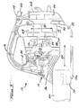
- the blower 10 generally comprises a housing 12 having an airflow discharge port 14 at a forward housing area 12a, a handle 16, a volute portion 18 at a rearward housing area 12b, an airflow intake port 20 for drawing air into the blower, and a wand assembly 22 coupled to the airflow discharge port 14.
- the blower 10 may be held with one hand at the user's side, as shown, or suspended via a shoulder strap along the user's side or behind the user.
- the blower 10 includes an AC power receptacle 24 disposed within a molded shroud 26. It will be appreciated, however, that the blower 10 could be readily adapted for use with a battery, and thus form a cordless blower, without departing from the spirit of the appended claims.
- the blower 10 incorporates a fan or impeller 28 which is disposed within a plane, represented by arrow 31, perpendicularly to a longitudinal axis 29 extending along the airflow discharge port 14.
- the fan 28 comprises a radial flow fan which resides within the volute 18 and draws in air through the slots 20 in the housing 12.
- the fan 28 is disposed within the volute 18 such that the radial airflow output of the fan is directed over a substantially 90° bend 30 in the volute 18 and thereafter out through the airflow discharge port 14.
- An electric motor 32 is supported within the housing 12 forwardly of the fan 28. It will be noted that a longitudinal motor axis 33 of the motor 32 is thus disposed parallel to longitudinal axis 29.
- the motor 32 is disposed in a generally horizontal orientation (i.e., with the longitudinal axis 33 parallel to axis 29) within the housing 12 with its output shaft 34 coupled to the fan 28.
- a user actuatable switch 35 is operatively coupled to the motor 32 for turning the motor 32 on and off.
- This mounting of the fan 28 is in contrast to many previously developed blowers, which have the fan mounted in a horizontal orientation (i.e., parallel to axis 29) within the housing, and wherein a vertically mounted motor drives the horizontally mounted fan.
- the housing 12 also provides a noise reduction benefit by forming the bend 30 of the volute 18 such that it protrudes below a peripheral edge 40 of the fan 28.
- a significant degree of noise attenuation is achieved.
- the volute 18 associated with the fan 28 will also be disposed at the rear housing area.
- the volute 18 will be slightly behind the user's leg or hip 42 ( Figure 4) when the blower 10 is being held or suspended from one side of the user. This produces a more stable feeling of the blower.
- This also adds significantly to the comfort and convenience in using the blower 10 because the volute 18, which forms a protrusion on the housing 12, will not rub or bounce off the user's leg or hip while the blower 10 is being held or suspended along the user's side.
- the rearward position of the volute 30 of the blower 10 provides a significant added degree of comfort to the user and also reduces user fatigue when it is necessary to operate the blower 10 for extended periods of time. Locating the fan 28 at the rear housing area also allows for a more compact layout, in part due to the ability to take advantage of the area under the motor 32 the airflow transition from the volute 18 to the airflow discharge port 14.
Landscapes
- Life Sciences & Earth Sciences (AREA)
- Environmental Sciences (AREA)
- Engineering & Computer Science (AREA)
- Architecture (AREA)
- Civil Engineering (AREA)
- Structural Engineering (AREA)
- Structures Of Non-Positive Displacement Pumps (AREA)
- Polarising Elements (AREA)
- Crystals, And After-Treatments Of Crystals (AREA)
Abstract
Description
Claims (16)
- A blower comprising:a housing having a forward portion and a rear portion, said forward portion having an airflow discharge port;an electric motor disposed within said housing, said electric motor having its longitudinal axis disposed generally parallel to a longitudinal axis of said airflow discharge port;a fan driven by an output shaft of said motor and disposed within said housing at said rear portion of said housing generally orthogonal to said longitudinal axis of said airflow discharge port; anda volute airflow channel formed in said housing adjacent said motor at said rear portion of said housing for directing airflow generated by said fan to said discharge port.
- The blower of claim 1, wherein said volute further comprises a substantially 90 degree bend for directing said airflow toward said airflow discharge port.
- The blower of claim 2, wherein said 90 degree bend is formed to block line-of-sight communication between said airflow discharge port and a peripheral edge of said fan, to thereby reduce noise generated by said blower.
- The blower of claim 1, wherein said housing includes a handle; and
wherein said handle is located vertically over said motor. - A blower comprising:a housing having a forward portion and a rear portion, said forward portion having an airflow discharge port;an electric motor disposed within said housing, said electric motor having its longitudinal axis disposed generally parallel to a longitudinal axis of said discharge port;a fan driven by an output shaft of said motor and disposed within said housing at said rear portion of said housing generally orthogonal to said longitudinal axis of said airflow discharge port;a volute airflow channel formed in said housing adjacent said motor at said rear portion of said housing for directing airflow generated by said fan to said airflow discharge port;said volute including a substantially 90 degree bend substantially impeding line-of-sight communication to a peripheral edge of said fan.
- The blower of claim 5, wherein said housing further comprises a handle graspable by a user, said handle being located vertically over said motor.
- A blower comprising:a housing having a forward portion and a rear portion, said forward portion having an airflow discharge port;an electric motor disposed within said housing, said electric motor having its longitudinal axis disposed generally parallel to a longitudinal axis of said airflow discharge port;a fan driven by an output shaft of said motor and disposed within said housing at said rear portion of said housing generally orthogonally to said longitudinal axis of said airflow discharge port;a volute airflow channel formed in said housing adjacent said motor at said rear portion of said housing for directing airflow generated by said fan to said airflow discharge port;said volute being formed within said housing so as to form a bulge protruding from said housing at said rear portion to thus eliminate interference with hip and leg areas of a user when said blower is carried by a user and rests along one side of the user's body, said bulge further helping to cradle said housing against said user's body.
- The blower of claim 7, wherein said volute includes a substantially 90 degree bend communicating with said airflow discharge port and a peripheral area of said fan.
- The blower of claim 8, wherein said 90 degree bend blocks line-of-sight communication between said airflow discharge port and a peripheral edge of said fan to thereby provide a noise reduction function for said blower.
- The blower of claim 7, wherein said housing further includes a handle graspable by said user, said handle being located substantially directly vertically over said motor and forwardly of said volute.
- A blower comprising:a housing having an airflow discharge port and a volute formed in said housing generally perpendicularly to said airflow discharge port and at a rear portion of said housing;a radial airflow fan disposed within said housing to generate an airflow into said volute, said fan being disposed generally perpendicularly to said airflow discharge port; anda motor disposed within said housing for driving said fan, said motor being oriented such that a longitudinal motor axis thereof is generally parallel to a longitudinal axis extending along said airflow discharge port.
- The blower of claim 11, wherein said volute rests behind a leg of a user when said blower is held by said user at said user's side.
- The blower of claim 11, wherein said volute rests behind a hip of a user when said blower is suspended via a shoulder strap along side a hip of said user.
- The blower of claim 11, wherein said volute includes a 90 degree bend which blocks a line-of-sight between said airflow discharge port and a peripheral edge of said fan, to thereby help reduce noise generated by said blower during operation thereof.
- A blower comprising:wherein said volute includes a substantially 90 degree bend for directing said airflow generated by said fan into said airflow discharge port; anda housing having an airflow discharge port and a volute formed in said housing generally perpendicularly to said airflow discharge port;a radial airflow fan disposed within said housing to generate an airflow into said volute, said fan being disposed generally perpendicularly to said airflow discharge port;a motor for driving said fan;
wherein said volute is disposed at a rear portion of said housing so as not to interfere with a user's leg or hip when said blower is positioned alongside said user during operation thereof. - The blower of claim 15, wherein said 90 degree bend of said volute protrudes so as to block line-of-sight communication from said airflow discharge port to a peripheral edge of said fan, to thereby attenuate noise generated by said blower during operation thereof.
Priority Applications (1)
| Application Number | Priority Date | Filing Date | Title |
|---|---|---|---|
| EP07104545A EP1795653B1 (en) | 2001-04-27 | 2002-04-26 | Blower having fan oriented perpendicular to discharge nozzle |
Applications Claiming Priority (2)
| Application Number | Priority Date | Filing Date | Title |
|---|---|---|---|
| US844657 | 2001-04-27 | ||
| US09/844,657 US6490756B2 (en) | 2001-04-27 | 2001-04-27 | Blower having fan oriented perpendicular to discharge nozzle |
Related Child Applications (1)
| Application Number | Title | Priority Date | Filing Date |
|---|---|---|---|
| EP07104545A Division EP1795653B1 (en) | 2001-04-27 | 2002-04-26 | Blower having fan oriented perpendicular to discharge nozzle |
Publications (3)
| Publication Number | Publication Date |
|---|---|
| EP1253250A2 true EP1253250A2 (en) | 2002-10-30 |
| EP1253250A3 EP1253250A3 (en) | 2003-12-10 |
| EP1253250B1 EP1253250B1 (en) | 2007-06-13 |
Family
ID=25293322
Family Applications (2)
| Application Number | Title | Priority Date | Filing Date |
|---|---|---|---|
| EP02253003A Expired - Lifetime EP1253250B1 (en) | 2001-04-27 | 2002-04-26 | Blower having fan oriented perpendicular to discharge nozzle |
| EP07104545A Expired - Lifetime EP1795653B1 (en) | 2001-04-27 | 2002-04-26 | Blower having fan oriented perpendicular to discharge nozzle |
Family Applications After (1)
| Application Number | Title | Priority Date | Filing Date |
|---|---|---|---|
| EP07104545A Expired - Lifetime EP1795653B1 (en) | 2001-04-27 | 2002-04-26 | Blower having fan oriented perpendicular to discharge nozzle |
Country Status (5)
| Country | Link |
|---|---|
| US (2) | US6490756B2 (en) |
| EP (2) | EP1253250B1 (en) |
| AT (1) | ATE364753T1 (en) |
| AU (1) | AU779539B2 (en) |
| DE (1) | DE60220581T2 (en) |
Cited By (2)
| Publication number | Priority date | Publication date | Assignee | Title |
|---|---|---|---|---|
| GB2513229A (en) * | 2013-02-20 | 2014-10-22 | Chervon Hk Ltd | Handheld Blower |
| GB2513230A (en) * | 2013-02-20 | 2014-10-22 | Chervon Hk Ltd | Handheld blower |
Families Citing this family (18)
| Publication number | Priority date | Publication date | Assignee | Title |
|---|---|---|---|---|
| US6490756B2 (en) * | 2001-04-27 | 2002-12-10 | Black & Decker Inc. | Blower having fan oriented perpendicular to discharge nozzle |
| US6640384B2 (en) * | 2001-10-10 | 2003-11-04 | Electrolux Home Products, Inc. | Convertible blower and vacuum |
| JP3979097B2 (en) * | 2002-01-22 | 2007-09-19 | 日本板硝子株式会社 | Optical element |
| US20050138766A1 (en) * | 2003-12-29 | 2005-06-30 | Curtis Lee | Duel blower |
| US7377274B2 (en) * | 2004-05-12 | 2008-05-27 | High Tech High Foundation | Rapid-firing toy gun |
| CN103894370B (en) * | 2012-12-28 | 2017-06-06 | 苏州宝时得电动工具有限公司 | Handheld blowing sucking machine |
| US10433497B2 (en) * | 2015-04-09 | 2019-10-08 | Canadian Tire Corporation, Limited | Portable leaf blower |
| AU2020205211B2 (en) | 2019-08-02 | 2026-01-15 | Techtronic Cordless Gp | Blowers having noise reduction features |
| CN214742186U (en) | 2020-01-21 | 2021-11-16 | 创科无线普通合伙 | Blower fan |
| AU2020286200A1 (en) | 2020-01-21 | 2021-08-05 | Techtronic Cordless Gp | Power tool having noise reduction features |
| KR102364693B1 (en) | 2020-05-12 | 2022-02-18 | 엘지전자 주식회사 | Hair dryer |
| KR102384524B1 (en) | 2020-05-12 | 2022-04-08 | 엘지전자 주식회사 | Hair dryer |
| KR102366465B1 (en) * | 2020-05-12 | 2022-02-23 | 엘지전자 주식회사 | Hair dryer |
| CN112064554B (en) * | 2020-08-06 | 2022-12-09 | 广州天翔建设工程有限公司 | Environment-friendly highway machinery is with dispersion exhaust device |
| USD1077859S1 (en) | 2020-11-17 | 2025-06-03 | Milwaukee Electric Tool Corporation | Blower |
| US11889794B2 (en) | 2020-12-30 | 2024-02-06 | Milwaukee Electric Tool Corporation | Handheld blower |
| DE112022003963T5 (en) | 2021-10-11 | 2024-07-04 | Milwaukee Electric Tool Corporation | BLOWER FOR A HANDHELD BLOWER |
| US12352274B2 (en) | 2022-03-21 | 2025-07-08 | Milwaukee Electric Tool Corporation | Axial blower |
Family Cites Families (19)
| Publication number | Priority date | Publication date | Assignee | Title |
|---|---|---|---|---|
| US4120616A (en) * | 1975-10-06 | 1978-10-17 | Breuer Electric Manufacturing Company | Vacuum cleaner-blower assembly with sound absorbing arrangement |
| BE852330A (en) * | 1977-03-10 | 1977-07-01 | Vandeclisse Zephir | VACUUM |
| US4213224A (en) * | 1978-08-21 | 1980-07-22 | Shop-Vac Corporation | By-pass type portable vacuum cleaner |
| US4325163A (en) * | 1980-04-07 | 1982-04-20 | Allegretti & Company | Portable blower-vacuum unit |
| US4451951A (en) | 1982-09-15 | 1984-06-05 | Kioritz Corporation | Engine-driven blower/dust collector |
| US4615069A (en) * | 1984-10-19 | 1986-10-07 | Black & Decker Inc. | Apparatus for collecting debris |
| US4644606A (en) * | 1985-04-08 | 1987-02-24 | Mcculloch Corporation | Lawn/garden blower/vacuum |
| US4799287A (en) * | 1987-05-04 | 1989-01-24 | Belanger, Inc. | Blower housing construction |
| US4870714A (en) * | 1987-11-09 | 1989-10-03 | Black & Decker Inc. | Portable blower/vacuum system |
| US4945604A (en) * | 1987-11-12 | 1990-08-07 | Black & Decker Inc. | Portable blower |
| GB9501751D0 (en) | 1995-01-30 | 1995-03-22 | Black & Decker Inc | Debris blower and/or vacuum devices |
| GB2299749B (en) * | 1995-03-11 | 1998-09-02 | Black & Decker Inc | A blower vacuum device of improved design |
| US5638574A (en) * | 1995-07-21 | 1997-06-17 | Wci Outdoor Products, Inc. | Convertible leaf blower and vacuum |
| GB9517995D0 (en) * | 1995-09-04 | 1995-11-08 | Black & Decker Inc | A debris blowing apparatus |
| US6141823A (en) * | 1996-02-21 | 2000-11-07 | Ryobi Limited | Blower and vacuum device |
| JP3910703B2 (en) | 1997-11-14 | 2007-04-25 | 株式会社共立 | Portable air blower |
| US6000096A (en) * | 1998-07-23 | 1999-12-14 | Ryobi North America, Inc. | Gasoline powered parallel tube blower/vacuum |
| US6305048B1 (en) * | 1999-03-03 | 2001-10-23 | Harold Salisian | Electric backpack blower and accessory operator |
| US6490756B2 (en) * | 2001-04-27 | 2002-12-10 | Black & Decker Inc. | Blower having fan oriented perpendicular to discharge nozzle |
-
2001
- 2001-04-27 US US09/844,657 patent/US6490756B2/en not_active Expired - Lifetime
-
2002
- 2002-04-26 AU AU37042/02A patent/AU779539B2/en not_active Ceased
- 2002-04-26 DE DE60220581T patent/DE60220581T2/en not_active Expired - Lifetime
- 2002-04-26 EP EP02253003A patent/EP1253250B1/en not_active Expired - Lifetime
- 2002-04-26 EP EP07104545A patent/EP1795653B1/en not_active Expired - Lifetime
- 2002-04-26 AT AT02253003T patent/ATE364753T1/en not_active IP Right Cessation
- 2002-10-22 US US10/277,597 patent/US6637069B2/en not_active Expired - Lifetime
Cited By (3)
| Publication number | Priority date | Publication date | Assignee | Title |
|---|---|---|---|---|
| GB2513229A (en) * | 2013-02-20 | 2014-10-22 | Chervon Hk Ltd | Handheld Blower |
| GB2513230A (en) * | 2013-02-20 | 2014-10-22 | Chervon Hk Ltd | Handheld blower |
| GB2513229B (en) * | 2013-02-20 | 2017-11-22 | Chervon Hk Ltd | Handheld Blower |
Also Published As
| Publication number | Publication date |
|---|---|
| DE60220581T2 (en) | 2008-02-14 |
| US20020157211A1 (en) | 2002-10-31 |
| EP1795653A2 (en) | 2007-06-13 |
| AU3704202A (en) | 2002-10-31 |
| ATE364753T1 (en) | 2007-07-15 |
| EP1795653B1 (en) | 2013-01-09 |
| US6490756B2 (en) | 2002-12-10 |
| US20030033689A1 (en) | 2003-02-20 |
| EP1253250A3 (en) | 2003-12-10 |
| US6637069B2 (en) | 2003-10-28 |
| DE60220581D1 (en) | 2007-07-26 |
| EP1795653A3 (en) | 2007-11-14 |
| EP1253250B1 (en) | 2007-06-13 |
| AU779539B2 (en) | 2005-01-27 |
Similar Documents
| Publication | Publication Date | Title |
|---|---|---|
| US6490756B2 (en) | Blower having fan oriented perpendicular to discharge nozzle | |
| EP1269901B1 (en) | Vacuum cleaner having airflow recirculation path for cooling beater brush motor | |
| EP4255271B1 (en) | Vacuum cleaner | |
| US6473933B2 (en) | Belt-mounted vacuum apparatus and methods | |
| US5388303A (en) | Vacuum cleaner with extendable hose and brush disengagement | |
| EP0671244B1 (en) | Random orbit sander having air directing baffle | |
| US8032980B2 (en) | Harness for backpack blower | |
| US20140007370A1 (en) | Backpack leaf blower | |
| US8539637B2 (en) | Harness for backpack blower | |
| JP7254636B2 (en) | Blower | |
| DE602004032068D1 (en) | Portable vacuum cleaner | |
| CN106231970A (en) | Has perforated aerator | |
| CN112081763A (en) | Blower fan | |
| US5388302A (en) | Vacuum cleaner housing and airflow chamber | |
| EP1295557A2 (en) | Method and apparatus for dampening the noise of a vacuum cleaner | |
| EP1601486A1 (en) | Method and apparatus for removing dust from a workpiece | |
| EP1491126A2 (en) | Vacuum cleaner | |
| WO2005049926A1 (en) | Cooling system for a blower | |
| EP2982481A1 (en) | Power head for a portable handheld tool | |
| JP2020031970A (en) | Vacuum cleaner | |
| JP2020031969A (en) | Vacuum cleaner |
Legal Events
| Date | Code | Title | Description |
|---|---|---|---|
| PUAI | Public reference made under article 153(3) epc to a published international application that has entered the european phase |
Free format text: ORIGINAL CODE: 0009012 |
|
| AK | Designated contracting states |
Kind code of ref document: A2 Designated state(s): AT BE CH CY DE DK ES FI FR GB GR IE IT LI LU MC NL PT SE TR |
|
| AX | Request for extension of the european patent |
Free format text: AL;LT;LV;MK;RO;SI |
|
| PUAL | Search report despatched |
Free format text: ORIGINAL CODE: 0009013 |
|
| AK | Designated contracting states |
Kind code of ref document: A3 Designated state(s): AT BE CH CY DE DK ES FI FR GB GR IE IT LI LU MC NL PT SE TR |
|
| AX | Request for extension of the european patent |
Extension state: AL LT LV MK RO SI |
|
| 17P | Request for examination filed |
Effective date: 20040224 |
|
| 17Q | First examination report despatched |
Effective date: 20040407 |
|
| AKX | Designation fees paid |
Designated state(s): AT BE CH CY DE DK ES FI FR GB GR IE IT LI LU MC NL PT SE TR |
|
| GRAP | Despatch of communication of intention to grant a patent |
Free format text: ORIGINAL CODE: EPIDOSNIGR1 |
|
| GRAS | Grant fee paid |
Free format text: ORIGINAL CODE: EPIDOSNIGR3 |
|
| GRAA | (expected) grant |
Free format text: ORIGINAL CODE: 0009210 |
|
| AK | Designated contracting states |
Kind code of ref document: B1 Designated state(s): AT BE CH CY DE DK ES FI FR GB GR IE IT LI LU MC NL PT SE TR |
|
| REG | Reference to a national code |
Ref country code: GB Ref legal event code: FG4D |
|
| REG | Reference to a national code |
Ref country code: CH Ref legal event code: EP |
|
| REG | Reference to a national code |
Ref country code: IE Ref legal event code: FG4D |
|
| REF | Corresponds to: |
Ref document number: 60220581 Country of ref document: DE Date of ref document: 20070726 Kind code of ref document: P |
|
| REG | Reference to a national code |
Ref country code: SE Ref legal event code: TRGR |
|
| REG | Reference to a national code |
Ref country code: CH Ref legal event code: NV Representative=s name: E. BLUM & CO. AG PATENT- UND MARKENANWAELTE VSP |
|
| ET | Fr: translation filed | ||
| PG25 | Lapsed in a contracting state [announced via postgrant information from national office to epo] |
Ref country code: BE Free format text: LAPSE BECAUSE OF FAILURE TO SUBMIT A TRANSLATION OF THE DESCRIPTION OR TO PAY THE FEE WITHIN THE PRESCRIBED TIME-LIMIT Effective date: 20070613 |
|
| PG25 | Lapsed in a contracting state [announced via postgrant information from national office to epo] |
Ref country code: PT Free format text: LAPSE BECAUSE OF FAILURE TO SUBMIT A TRANSLATION OF THE DESCRIPTION OR TO PAY THE FEE WITHIN THE PRESCRIBED TIME-LIMIT Effective date: 20071113 Ref country code: ES Free format text: LAPSE BECAUSE OF FAILURE TO SUBMIT A TRANSLATION OF THE DESCRIPTION OR TO PAY THE FEE WITHIN THE PRESCRIBED TIME-LIMIT Effective date: 20070924 |
|
| PLBE | No opposition filed within time limit |
Free format text: ORIGINAL CODE: 0009261 |
|
| STAA | Information on the status of an ep patent application or granted ep patent |
Free format text: STATUS: NO OPPOSITION FILED WITHIN TIME LIMIT |
|
| PG25 | Lapsed in a contracting state [announced via postgrant information from national office to epo] |
Ref country code: GR Free format text: LAPSE BECAUSE OF FAILURE TO SUBMIT A TRANSLATION OF THE DESCRIPTION OR TO PAY THE FEE WITHIN THE PRESCRIBED TIME-LIMIT Effective date: 20070914 Ref country code: DK Free format text: LAPSE BECAUSE OF FAILURE TO SUBMIT A TRANSLATION OF THE DESCRIPTION OR TO PAY THE FEE WITHIN THE PRESCRIBED TIME-LIMIT Effective date: 20070613 |
|
| 26N | No opposition filed |
Effective date: 20080314 |
|
| PG25 | Lapsed in a contracting state [announced via postgrant information from national office to epo] |
Ref country code: MC Free format text: LAPSE BECAUSE OF NON-PAYMENT OF DUE FEES Effective date: 20080430 |
|
| PG25 | Lapsed in a contracting state [announced via postgrant information from national office to epo] |
Ref country code: FI Free format text: LAPSE BECAUSE OF FAILURE TO SUBMIT A TRANSLATION OF THE DESCRIPTION OR TO PAY THE FEE WITHIN THE PRESCRIBED TIME-LIMIT Effective date: 20070613 |
|
| PG25 | Lapsed in a contracting state [announced via postgrant information from national office to epo] |
Ref country code: CY Free format text: LAPSE BECAUSE OF FAILURE TO SUBMIT A TRANSLATION OF THE DESCRIPTION OR TO PAY THE FEE WITHIN THE PRESCRIBED TIME-LIMIT Effective date: 20070613 |
|
| PGFP | Annual fee paid to national office [announced via postgrant information from national office to epo] |
Ref country code: IE Payment date: 20090427 Year of fee payment: 8 |
|
| PGFP | Annual fee paid to national office [announced via postgrant information from national office to epo] |
Ref country code: AT Payment date: 20090401 Year of fee payment: 8 Ref country code: SE Payment date: 20090429 Year of fee payment: 8 |
|
| PGFP | Annual fee paid to national office [announced via postgrant information from national office to epo] |
Ref country code: CH Payment date: 20090427 Year of fee payment: 8 |
|
| PG25 | Lapsed in a contracting state [announced via postgrant information from national office to epo] |
Ref country code: LU Free format text: LAPSE BECAUSE OF NON-PAYMENT OF DUE FEES Effective date: 20080426 |
|
| PG25 | Lapsed in a contracting state [announced via postgrant information from national office to epo] |
Ref country code: TR Free format text: LAPSE BECAUSE OF FAILURE TO SUBMIT A TRANSLATION OF THE DESCRIPTION OR TO PAY THE FEE WITHIN THE PRESCRIBED TIME-LIMIT Effective date: 20070613 |
|
| EUG | Se: european patent has lapsed | ||
| REG | Reference to a national code |
Ref country code: CH Ref legal event code: PL |
|
| PG25 | Lapsed in a contracting state [announced via postgrant information from national office to epo] |
Ref country code: IE Free format text: LAPSE BECAUSE OF NON-PAYMENT OF DUE FEES Effective date: 20100426 Ref country code: AT Free format text: LAPSE BECAUSE OF NON-PAYMENT OF DUE FEES Effective date: 20100426 |
|
| PG25 | Lapsed in a contracting state [announced via postgrant information from national office to epo] |
Ref country code: LI Free format text: LAPSE BECAUSE OF NON-PAYMENT OF DUE FEES Effective date: 20100430 Ref country code: CH Free format text: LAPSE BECAUSE OF NON-PAYMENT OF DUE FEES Effective date: 20100430 |
|
| PG25 | Lapsed in a contracting state [announced via postgrant information from national office to epo] |
Ref country code: SE Free format text: LAPSE BECAUSE OF NON-PAYMENT OF DUE FEES Effective date: 20100427 |
|
| REG | Reference to a national code |
Ref country code: FR Ref legal event code: PLFP Year of fee payment: 14 |
|
| PGFP | Annual fee paid to national office [announced via postgrant information from national office to epo] |
Ref country code: NL Payment date: 20150426 Year of fee payment: 14 |
|
| PGFP | Annual fee paid to national office [announced via postgrant information from national office to epo] |
Ref country code: GB Payment date: 20150427 Year of fee payment: 14 Ref country code: DE Payment date: 20150429 Year of fee payment: 14 |
|
| PGFP | Annual fee paid to national office [announced via postgrant information from national office to epo] |
Ref country code: IT Payment date: 20150427 Year of fee payment: 14 Ref country code: FR Payment date: 20150417 Year of fee payment: 14 |
|
| REG | Reference to a national code |
Ref country code: DE Ref legal event code: R119 Ref document number: 60220581 Country of ref document: DE |
|
| REG | Reference to a national code |
Ref country code: NL Ref legal event code: MM Effective date: 20160501 |
|
| GBPC | Gb: european patent ceased through non-payment of renewal fee |
Effective date: 20160426 |
|
| REG | Reference to a national code |
Ref country code: FR Ref legal event code: ST Effective date: 20161230 |
|
| PG25 | Lapsed in a contracting state [announced via postgrant information from national office to epo] |
Ref country code: DE Free format text: LAPSE BECAUSE OF NON-PAYMENT OF DUE FEES Effective date: 20161101 Ref country code: NL Free format text: LAPSE BECAUSE OF NON-PAYMENT OF DUE FEES Effective date: 20160501 Ref country code: GB Free format text: LAPSE BECAUSE OF NON-PAYMENT OF DUE FEES Effective date: 20160426 Ref country code: FR Free format text: LAPSE BECAUSE OF NON-PAYMENT OF DUE FEES Effective date: 20160502 |
|
| PG25 | Lapsed in a contracting state [announced via postgrant information from national office to epo] |
Ref country code: IT Free format text: LAPSE BECAUSE OF NON-PAYMENT OF DUE FEES Effective date: 20160426 |