EP1253100A2 - Support tube for winding yarn on a quill - Google Patents
Support tube for winding yarn on a quill Download PDFInfo
- Publication number
- EP1253100A2 EP1253100A2 EP02008826A EP02008826A EP1253100A2 EP 1253100 A2 EP1253100 A2 EP 1253100A2 EP 02008826 A EP02008826 A EP 02008826A EP 02008826 A EP02008826 A EP 02008826A EP 1253100 A2 EP1253100 A2 EP 1253100A2
- Authority
- EP
- European Patent Office
- Prior art keywords
- tube
- indentations
- winding
- support tube
- quill
- Prior art date
- Legal status (The legal status is an assumption and is not a legal conclusion. Google has not performed a legal analysis and makes no representation as to the accuracy of the status listed.)
- Granted
Links
Images


Classifications
-
- B—PERFORMING OPERATIONS; TRANSPORTING
- B65—CONVEYING; PACKING; STORING; HANDLING THIN OR FILAMENTARY MATERIAL
- B65H—HANDLING THIN OR FILAMENTARY MATERIAL, e.g. SHEETS, WEBS, CABLES
- B65H75/00—Storing webs, tapes, or filamentary material, e.g. on reels
- B65H75/02—Cores, formers, supports, or holders for coiled, wound, or folded material, e.g. reels, spindles, bobbins, cop tubes, cans, mandrels or chucks
- B65H75/18—Constructional details
- B65H75/28—Arrangements for positively securing ends of material
-
- B—PERFORMING OPERATIONS; TRANSPORTING
- B65—CONVEYING; PACKING; STORING; HANDLING THIN OR FILAMENTARY MATERIAL
- B65H—HANDLING THIN OR FILAMENTARY MATERIAL, e.g. SHEETS, WEBS, CABLES
- B65H2701/00—Handled material; Storage means
- B65H2701/30—Handled filamentary material
- B65H2701/31—Textiles threads or artificial strands of filaments
Definitions
- the finding regards a support tube for winding yarn on a quill.
- the yarn thus produced therefore needs to be wound onto a suitable support for forming the quill.
- Consisting of a tubular body defined with the generic term "tube” and realised in cardboard or in another material suitable for the purpose, which is equipped on its side surface with an indentation for attaching or intercepting the end of the yarn to be wound on the support itself and where both the interception of the yarn and it subsequent winding on the tubular body take place with per se known automatic devices substantially resembling winding reels rotating on their own longitudinal axis, on which the tube to be wound is threaded.
- Such a yarn-capturing indentation can take on different configurations, according to the characteristics of the yarn to be wound, all of which however can be sorted into three types:
- the yarn-gathering indentation associated or not with a yarn-blocking indentation, is formed on the side surface of the tubular body and more precisely on one of the two edges, or close to one of them, which defines one of the two ends of the side surface of the body itself.
- the tube as well as, obviously, being able to be mounted on winding machines on a single side, is suitable for being mounted only on a winding reel which has a specific direction of rotation, that corresponding to the inclination of the yarn-capturing indentation formed on the tube itself for which reason if winding machines are used with winding reels which rotate with opposite directions of rotation it is necessary to have stored two different types of "tubes", to the great disadvantage of the productivity.
- the purpose of the present finding is that of foreseeing a tube for winding yarn which can be mounted on winding reels, independently from their direction of rotation.
- a further purpose of the finding is that of foreseeing a tube for winding yarn which can be threaded on a winding reel on both its sides.
- a further, but no less important purpose of the finding is that of foreseeing a tube for winding yarn which allows at least two packages or hanks to be realised on a single support consisting of the tube itself.
- a further purpose of the finding is that of foreseeing a tube for winding yarn which ensures a greater productivity (increase in the amount of yarn wound per hour worked) with respect to suchlike known products.
- the indentations have a profile which is preferably symmetrical with respect to the longitudinal axis of the tube, so as to allow the attaching of the yarn independently of the direction of rotation of the tube itself.
- the tube for winding yarn on a quill consists of a tubular, cylindrical or frustum of cone body 1, upon the side surface 2 of which indentations 3 are formed in which the end of the wound yarn attaches.
- the indentation 3.1 of the yarn-catching type, consists of a circumferential cut in which an angular portion 3.11 has a greater width and depth with respect to the remaining angular portion 3.12.
- the indentation 3.2 of the simple notch type, consists of a through-opening equipped with an oblique portion 3.21, to realise the attachment of the yarn and with a slit 3.22 for stopping the yarn itself.
- the indentation 3.3 of the window notch type, consists of a through-opening 3.31, for attaching the yarn, possibly associated with a circumferential cut 3.32, for locking the yarn itself.
- the tube according to the finding is represented in which the single tubular body 1 is equipped with two indentations, a first simple notch indentation 3.2 formed on the outer edge 4, and a second window notch indentation 3.3 arranged in an intermediate position on the side surface 2, respectively, so as to allow the winding of the two hanks 5 on the same body.
- the tube according to the finding is represented which has two indentations 6.1 and 6.2 formed on the edges, being arranged opposite one another and with symmetrical profiles, so as to allow the winding of the quill 7 on both sides of the tube itself.
- indentations are formed: two indentations 8.1 and 8.2 on the edges and one intermediate indentation 9 on the side surface which have a symmetrical profile with respect to a diametric plane passing through the axis "Z" of the tube, the intermediate indentation also having a symmetrical profile with respect to the plane " ⁇ ", passing through the midpoint line "K” of said indentation and perpendicular to the axis "Z" of the tube itself.
Landscapes
- Storage Of Web-Like Or Filamentary Materials (AREA)
- Winding Filamentary Materials (AREA)
- Medicines Containing Plant Substances (AREA)
- Medicines That Contain Protein Lipid Enzymes And Other Medicines (AREA)
- Pharmaceuticals Containing Other Organic And Inorganic Compounds (AREA)
Abstract
Description
- The finding regards a support tube for winding yarn on a quill.
- As is known, the manufacture of synthetic and artificial textile fibres can take place with different procedures but which all have in common the extrusion step, with which, through a spinneret equipped with capillary holes, the melted product, by coagulation or by cooling, is transformed into bands of elementary thread which constitute the so-called "filament" or yarn.
- The yarn thus produced therefore needs to be wound onto a suitable support for forming the quill. Consisting of a tubular body, defined with the generic term "tube" and realised in cardboard or in another material suitable for the purpose, which is equipped on its side surface with an indentation for attaching or intercepting the end of the yarn to be wound on the support itself and where both the interception of the yarn and it subsequent winding on the tubular body take place with per se known automatic devices substantially resembling winding reels rotating on their own longitudinal axis, on which the tube to be wound is threaded.
- Such a yarn-capturing indentation can take on different configurations, according to the characteristics of the yarn to be wound, all of which however can be sorted into three types:
- yarn-gathering cut: consists of a circumferential cut, in which the section of the groove has at least one first angular portion with a wider profile, which is used to capture the end of the yarn, and at least one remaining portion with a thinner profile, which is used to block the yarn itself, preventing sliding on the side surface and thus allowing its regular winding on the support.
- simple notch, possibly equipped with a yarn-blocking slit: consists of an opening, which engages the entire thickness of the tubular support body and has a profile in which at least one oblique portion is formed, specifically slightly inclined with respect to the direction perpendicular to the longitudinal axis of the tubular body and having the function of easing the interception and attaching of the end of the yarn on the body itself. A slit can be associated with the oblique portion which engages the yarn and blocks it preventing it from sliding on the side surface and therefore allowing its regular winding on the support.
- window notch, possibly equipped with a yarn-blocking cut: consists of a simple notch formed completely inside the side surface of the tube and thus equipped with a closed perimeter with which is, possibly, associated a circumferential cut which has the task of blocking the yarn, to allow its regular winding on the support.
- At the current state of the art the yarn-gathering indentation, associated or not with a yarn-blocking indentation, is formed on the side surface of the tubular body and more precisely on one of the two edges, or close to one of them, which defines one of the two ends of the side surface of the body itself.
- Nevertheless this constructive solution allows the possibility of attaching a single yarn to the tubular body and therefore it is possible to realise the winding of a single hank of wound yarn for every single tube.
- Moreover, with said constructive solution of the known type the tube, as well as, obviously, being able to be mounted on winding machines on a single side, is suitable for being mounted only on a winding reel which has a specific direction of rotation, that corresponding to the inclination of the yarn-capturing indentation formed on the tube itself for which reason if winding machines are used with winding reels which rotate with opposite directions of rotation it is necessary to have stored two different types of "tubes", to the great disadvantage of the productivity.
- The purpose of the present finding is that of foreseeing a tube for winding yarn which can be mounted on winding reels, independently from their direction of rotation.
- A further purpose of the finding is that of foreseeing a tube for winding yarn which can be threaded on a winding reel on both its sides.
- A further, but no less important purpose of the finding is that of foreseeing a tube for winding yarn which allows at least two packages or hanks to be realised on a single support consisting of the tube itself.
- A further purpose of the finding is that of foreseeing a tube for winding yarn which ensures a greater productivity (increase in the amount of yarn wound per hour worked) with respect to suchlike known products.
- Such purposes are obtained through the realisation of a tube equipped with at least two indentations, formed on its side surface.
- A first possible embodiment foresees forming two indentations on the side surface of the tube, a first indentation being formed near to or directly on one of the two outer edges of the surface itself and a second indentation being formed still on the same side surface but in an intermediate position between the two aforementioned edges, thus making the simultaneous winding of two hanks on a single support possible.
- In the same way, with three indentations, one formed on the edges and the others on the side surface and separated from each other by a third of the height of said surface, it is possible to simultaneously wind three hanks on a single support.
- A second possible embodiment foresees forming two indentations on the side surface of the tube, each arranged on one of the two outer edges of the surface itself; in such a way the winding of a single hank on a single support can be realised but there is the advantage that the tube can be mounted on the winding reel on either of the two sides irrespectively.
- The finding also foresees that the indentations have a profile which is preferably symmetrical with respect to the longitudinal axis of the tube, so as to allow the attaching of the yarn independently of the direction of rotation of the tube itself.
- Finally, the finding foresees that the indentations have a preferably symmetrical profile with respect to a midpoint plane perpendicular to the longitudinal axis, allowing the tube to be slotted onto the support winding reel, on one or the other side of the tube itself irrespectively.
- The finding shall be better illustrated through the description of some of its possible embodiments, given only as a non-limiting illustrative example, with the help of the attached tables of drawings, where:
- fig. 1 represents a perspective view of a tube according to the finding, equipped with indentations with different profiles, for attaching the yarn;
- fig. 2 represents a tube according to the finding equipped with two indentations;
- fig. 3 represents a tube according to fig. 2 with two wound hanks.
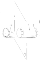
- fig. 4 represents a tube according to the finding equipped with two opposite indentations formed on the outer edges for winding a hank;
- fig. 5 represents a tube according to the finding with three wound hanks;
- fig. 6 represents a tube according to the finding equipped with indentations with a symmetrical profile.
- As can be seen in fig. 1, the tube for winding yarn on a quill consists of a tubular, cylindrical or frustum of
cone body 1, upon theside surface 2 of whichindentations 3 are formed in which the end of the wound yarn attaches. - The indentation 3.1, of the yarn-catching type, consists of a circumferential cut in which an angular portion 3.11 has a greater width and depth with respect to the remaining angular portion 3.12.
- The indentation 3.2, of the simple notch type, consists of a through-opening equipped with an oblique portion 3.21, to realise the attachment of the yarn and with a slit 3.22 for stopping the yarn itself.
- The indentation 3.3, of the window notch type, consists of a through-opening 3.31, for attaching the yarn, possibly associated with a circumferential cut 3.32, for locking the yarn itself.
- In figs. 2 and 3 the tube according to the finding is represented in which the single
tubular body 1 is equipped with two indentations, a first simple notch indentation 3.2 formed on the outer edge 4, and a second window notch indentation 3.3 arranged in an intermediate position on theside surface 2, respectively, so as to allow the winding of the twohanks 5 on the same body. - In fig. 4 the tube according to the finding is represented which has two indentations 6.1 and 6.2 formed on the edges, being arranged opposite one another and with symmetrical profiles, so as to allow the winding of the
quill 7 on both sides of the tube itself. - In fig. 5 a tube is represented with three
wound quills 8. - In fig. 6 on the tube three indentations are formed: two indentations 8.1 and 8.2 on the edges and one
intermediate indentation 9 on the side surface which have a symmetrical profile with respect to a diametric plane passing through the axis "Z" of the tube, the intermediate indentation also having a symmetrical profile with respect to the plane "α", passing through the midpoint line "K" of said indentation and perpendicular to the axis "Z" of the tube itself. - Obviously, different embodiments to those illustrated are also possible, such as different forms of indentation, as well as a different combination thereof on a single body or on a single circumferential arrangement without for this reason leaving the scope of the following claims.
Claims (13)
- SUPPORT TUBE FOR WINDING YARN ONTO A QUILL, made of cardboard or of another material suitable for the purpose and having a cylindrical or frustum of cone shape,
said tube characterised in that
it is equipped, on its side surface, with at least two indentations for attaching and intercepting the end of the yarn to be wound on the support itself. - SUPPORT TUBE FOR WINDING YARN ONTO A QUILL according to claim 1, characterised in that the indentations allow the attachment of at least two yarns and the winding and formation of at least two hanks on the same support.
- SUPPORT TUBE FOR WINDING YARN ONTO A QUILL according to claim 1 and 2, characterised in that a first indentation is formed near to or directly on one of the two outer edges of the side surface of the tubular body, whereas at least one other indentation is formed still on the same side surface, but in an intermediate position between the two aforementioned edges.
- SUPPORT TUBE FOR WINDING YARN ONTO A QUILL according to claim 1 and 2, characterised in that the two indentations formed on the side surface of the tube are each arranged on one of the two outer edges of the same surface.
- SUPPORT TUBE FOR WINDING YARN ONTO A QUILL according to claim 4, characterised in that the two indentations have a mutually symmetrical profile.
- SUPPORT TUBE FOR WINDING YARN ONTO A QUILL according to one or more of the previous claims, characterised in that the indentations have a symmetrical profile with respect to the longitudinal axis of the tube, to allow the attaching of the yarn independently of the direction of rotation of the tube itself.
- SUPPORT TUBE FOR WINDING YARN ONTO A QUILL according to one or more of the previous claims, characterised in that the indentations have a symmetrical profile with respect to a midpoint plane perpendicular to the longitudinal axis of the tube itself, to allow the tube to be slotted onto the support winding reel, irrespective of whether the tube itself goes is one direction or the opposite direction.
- SUPPORT TUBE FOR WINDING YARN ONTO A QUILL according to one or more of the previous claims, characterised in that the indentations are of different types and sizes, such as thread-gathering cuts, simple notches., possibly equipped with a yarn-locking slit, and a window notch, possibly equipped with a yarn-catching and yarn-capturing cut.
- SUPPORT TUBE FOR WINDING YARN ONTO A QUILL according to one or more of the previous claims, characterised in that it foresees a plurality of indentations formed on the single tubular body and they can all be of the same type and/or of different types and with different notch/cut combinations.
- SUPPORT TUBE FOR WINDING YARN ONTO A QUILL according to one or more of the previous claims, consisting of a tubular body (1) characterised in that on its side surface (2) two indentations (3) are formed, in which the two ends of the two wound threads attach, one of said two indentations being of the simple notch (3.2) type, formed on the outer edge (4) and the other being of the window notch (3.3) type, arranged in an intermediate position on the side surface (2) so as to allow the winding of the two hanks (5) on the same body.
- SUPPORT TUBE FOR WINDING YARN ONTO A QUILL according to one or more of the previous claims, consisting of a tubular body (1) characterised in that two indentations (6.1, 6.2) are formed on the edges (4), are arranged opposite each other and have mutually symmetrical profiles, so as to allow the winding of the quill (7) on both sides of the tube itself.
- SUPPORT TUBE FOR WINDING YARN ONTO A QUILL according to one or more of the previous claims, consisting of a tubular body (1) characterised in that it has three indentations, two indentations (9.1, 8.2) on the edges (4) and one intermediate indentation (9) on the side surface, said indentations having a preferably symmetrical profile with respect to a diametric plane passing through the axis (Z) of the tube.
- SUPPORT TUBE FOR WINDING YARN ONTO A QUILL according to one or more of the previous claims, consisting of a tubular body (1) characterised in that the intermediate indentation (9) on the side surface has a symmetrical profile with respect to the plane "α', passing through the midpoint line (K) of said indentation and perpendicular to the axis (Z) of the tube itself.
Applications Claiming Priority (3)
| Application Number | Priority Date | Filing Date | Title |
|---|---|---|---|
| IT2001VI000090A ITVI20010090A1 (en) | 2001-04-27 | 2001-04-27 | SUPPORT TUBE FOR WINDING OF YARNS IN THE REEL |
| ITVI20010090 | 2001-04-27 | ||
| US10/183,745 US6889925B2 (en) | 2001-04-27 | 2002-06-26 | Support tube for winding yarn on a bobbin |
Publications (3)
| Publication Number | Publication Date |
|---|---|
| EP1253100A2 true EP1253100A2 (en) | 2002-10-30 |
| EP1253100A3 EP1253100A3 (en) | 2003-07-16 |
| EP1253100B1 EP1253100B1 (en) | 2006-08-09 |
Family
ID=32299841
Family Applications (1)
| Application Number | Title | Priority Date | Filing Date |
|---|---|---|---|
| EP02008826A Expired - Lifetime EP1253100B1 (en) | 2001-04-27 | 2002-04-19 | Support tube for winding yarn on a quill |
Country Status (6)
| Country | Link |
|---|---|
| US (1) | US6889925B2 (en) |
| EP (1) | EP1253100B1 (en) |
| AT (1) | ATE335701T1 (en) |
| DE (1) | DE60213702T2 (en) |
| ES (1) | ES2269546T3 (en) |
| IT (1) | ITVI20010090A1 (en) |
Cited By (1)
| Publication number | Priority date | Publication date | Assignee | Title |
|---|---|---|---|---|
| WO2009088643A1 (en) * | 2008-01-03 | 2009-07-16 | Sonoco Development, Inc. | Yarn carrier |
Families Citing this family (4)
| Publication number | Priority date | Publication date | Assignee | Title |
|---|---|---|---|---|
| US20050017121A1 (en) * | 2003-07-24 | 2005-01-27 | Sonoco Development, Inc. | Yarn core |
| WO2012078678A1 (en) * | 2010-12-06 | 2012-06-14 | Tyco Healthcare Group Lp | Vascular remodeling device |
| ES1103306Y (en) * | 2014-01-29 | 2014-06-11 | Ind Sagarra S L | COIL HOLDER TUBE |
| US20190263621A1 (en) * | 2018-02-23 | 2019-08-29 | Bear Paper Tube, Llc | Core for winding yarn, method of winding yarn, bobbin, and method of cutting core |
Citations (8)
| Publication number | Priority date | Publication date | Assignee | Title |
|---|---|---|---|---|
| DE2602488A1 (en) * | 1976-01-23 | 1977-07-28 | Barmag Barmer Maschf | High speed polymeric yarn winding machine - has bobbins provided with one oblique radial face in which is formed yarn catcher to protect latter |
| US4050646A (en) * | 1975-12-05 | 1977-09-27 | Burchette Jr Robert L | Yarn carrier |
| US4063696A (en) * | 1976-08-23 | 1977-12-20 | Burlington Industries, Inc. | Slotted take-up package tube for open-end spinning machines |
| GB2056948A (en) * | 1979-07-23 | 1981-03-25 | Rhodia Ag | A support for yarns, filaments or the like |
| US4369933A (en) * | 1981-01-13 | 1983-01-25 | Sonoco Products Company | Yarn tube with pickup groove accommodating left hand and right hand pickup |
| US4371130A (en) * | 1981-01-13 | 1983-02-01 | Sonoco Products Company | Yarn tube with universal pickup groove |
| US4834314A (en) * | 1988-05-31 | 1989-05-30 | Stephen S. Powel | Reusable winding tube |
| US5927637A (en) * | 1996-11-13 | 1999-07-27 | Barmag Ag | Yarn winding bobbin |
Family Cites Families (8)
| Publication number | Priority date | Publication date | Assignee | Title |
|---|---|---|---|---|
| GB1175965A (en) * | 1966-09-28 | 1970-01-01 | Ici Ltd | Yarn winding. |
| US3767129A (en) * | 1971-10-05 | 1973-10-23 | Celanese Corp | Mandrel |
| US4050645A (en) * | 1975-10-08 | 1977-09-27 | Plastic Injectors, Inc. | Yarn carrier |
| CH608039A5 (en) * | 1976-07-02 | 1978-12-15 | Sulzer Ag | |
| US4936523A (en) * | 1988-10-14 | 1990-06-26 | Stephen S. Powel | Composite yarn carrier |
| JPH05208786A (en) * | 1991-07-20 | 1993-08-20 | Barmag Ag | Cylindrical wind pipe |
| US5791574A (en) * | 1996-03-18 | 1998-08-11 | Solutia, Inc. | Yarn bobbin with improved snagger |
| US6595456B2 (en) * | 2001-09-19 | 2003-07-22 | Sonoco Development, Inc. | Textile tube with start-up feature |
-
2001
- 2001-04-27 IT IT2001VI000090A patent/ITVI20010090A1/en unknown
-
2002
- 2002-04-19 AT AT02008826T patent/ATE335701T1/en not_active IP Right Cessation
- 2002-04-19 DE DE60213702T patent/DE60213702T2/en not_active Expired - Fee Related
- 2002-04-19 EP EP02008826A patent/EP1253100B1/en not_active Expired - Lifetime
- 2002-04-19 ES ES02008826T patent/ES2269546T3/en not_active Expired - Lifetime
- 2002-06-26 US US10/183,745 patent/US6889925B2/en not_active Expired - Fee Related
Patent Citations (8)
| Publication number | Priority date | Publication date | Assignee | Title |
|---|---|---|---|---|
| US4050646A (en) * | 1975-12-05 | 1977-09-27 | Burchette Jr Robert L | Yarn carrier |
| DE2602488A1 (en) * | 1976-01-23 | 1977-07-28 | Barmag Barmer Maschf | High speed polymeric yarn winding machine - has bobbins provided with one oblique radial face in which is formed yarn catcher to protect latter |
| US4063696A (en) * | 1976-08-23 | 1977-12-20 | Burlington Industries, Inc. | Slotted take-up package tube for open-end spinning machines |
| GB2056948A (en) * | 1979-07-23 | 1981-03-25 | Rhodia Ag | A support for yarns, filaments or the like |
| US4369933A (en) * | 1981-01-13 | 1983-01-25 | Sonoco Products Company | Yarn tube with pickup groove accommodating left hand and right hand pickup |
| US4371130A (en) * | 1981-01-13 | 1983-02-01 | Sonoco Products Company | Yarn tube with universal pickup groove |
| US4834314A (en) * | 1988-05-31 | 1989-05-30 | Stephen S. Powel | Reusable winding tube |
| US5927637A (en) * | 1996-11-13 | 1999-07-27 | Barmag Ag | Yarn winding bobbin |
Cited By (1)
| Publication number | Priority date | Publication date | Assignee | Title |
|---|---|---|---|---|
| WO2009088643A1 (en) * | 2008-01-03 | 2009-07-16 | Sonoco Development, Inc. | Yarn carrier |
Also Published As
| Publication number | Publication date |
|---|---|
| ES2269546T3 (en) | 2007-04-01 |
| ATE335701T1 (en) | 2006-09-15 |
| EP1253100A3 (en) | 2003-07-16 |
| US20040000610A1 (en) | 2004-01-01 |
| EP1253100B1 (en) | 2006-08-09 |
| US6889925B2 (en) | 2005-05-10 |
| ITVI20010090A1 (en) | 2002-10-27 |
| DE60213702T2 (en) | 2007-08-02 |
| DE60213702D1 (en) | 2006-09-21 |
Similar Documents
| Publication | Publication Date | Title |
|---|---|---|
| DE3437252C1 (en) | Thread storage and delivery device, in particular for textile machines | |
| EP1253100B1 (en) | Support tube for winding yarn on a quill | |
| US3967440A (en) | Device for cutting a tail-end of a yarn package formed on a base portion of each spindle in a textile machine | |
| CA2476236A1 (en) | Soft hand, low luster, high body carpet filaments | |
| DE3506490A1 (en) | DELIVERY DEVICE FOR RUNNING THREADS | |
| US20050188544A1 (en) | Noise-reducing cutting line for a vegetation cutting device | |
| KR920000315B1 (en) | Spinneret with seven holes | |
| GB843179A (en) | Method of melt spinning of synthetic organic linear high polymers | |
| DE2248875B2 (en) | Mandrel for exit bobbin tubes on automatic bobbin changing machines | |
| US4160532A (en) | Knot hole beam | |
| DE102007007987A1 (en) | Spiral cutting filament arrangement for trimmer i.e. filament trimmer, has cutting filaments detached from winding position with windings, and comprising coil with windings, where windings are detachably connected | |
| DE3106947A1 (en) | Winding apparatus for winding up flat threads to form cylindrical cross-wound bobbins | |
| ITMI961900A1 (en) | CIRCULAR MACHINE FOR KNITWEAR | |
| US4819892A (en) | Yarn carrier for winding a filamentary thread and a method of forming a thread reserve | |
| US7246764B2 (en) | Cross-wound bobbin | |
| KR840008180A (en) | Apparatus and method for cutting thread in predetermined length | |
| GB2104873A (en) | Bobbin | |
| JP2526976Y2 (en) | String thread | |
| US1962693A (en) | Flier block construction | |
| KR930000237B1 (en) | Spinnerets for triangular hollow fiber manufacturing | |
| JPH0711183Y2 (en) | Snell guide | |
| JPH0355582Y2 (en) | ||
| JPH07309537A (en) | Yarn winding paper tube | |
| JPH0543140A (en) | Filament winding bobbin | |
| JPH0330378Y2 (en) |
Legal Events
| Date | Code | Title | Description |
|---|---|---|---|
| PUAI | Public reference made under article 153(3) epc to a published international application that has entered the european phase |
Free format text: ORIGINAL CODE: 0009012 |
|
| AK | Designated contracting states |
Kind code of ref document: A2 Designated state(s): AT BE CH CY DE DK ES FI FR GB GR IE IT LI LU MC NL PT SE TR |
|
| AX | Request for extension of the european patent |
Free format text: AL;LT;LV;MK;RO;SI |
|
| PUAL | Search report despatched |
Free format text: ORIGINAL CODE: 0009013 |
|
| AK | Designated contracting states |
Designated state(s): AT BE CH CY DE DK ES FI FR GB GR IE IT LI LU MC NL PT SE TR |
|
| AX | Request for extension of the european patent |
Extension state: AL LT LV MK RO SI |
|
| 17P | Request for examination filed |
Effective date: 20031230 |
|
| AKX | Designation fees paid |
Designated state(s): AT BE CH CY DE DK ES FI FR GB GR IE IT LI LU MC NL PT SE TR |
|
| AXX | Extension fees paid |
Extension state: SI Payment date: 20031230 Extension state: RO Payment date: 20031230 Extension state: MK Payment date: 20031230 Extension state: LV Payment date: 20031230 Extension state: LT Payment date: 20031230 Extension state: AL Payment date: 20031230 |
|
| 17Q | First examination report despatched |
Effective date: 20050411 |
|
| GRAP | Despatch of communication of intention to grant a patent |
Free format text: ORIGINAL CODE: EPIDOSNIGR1 |
|
| GRAS | Grant fee paid |
Free format text: ORIGINAL CODE: EPIDOSNIGR3 |
|
| GRAA | (expected) grant |
Free format text: ORIGINAL CODE: 0009210 |
|
| AK | Designated contracting states |
Kind code of ref document: B1 Designated state(s): AT BE CH CY DE DK ES FI FR GB GR IE IT LI LU MC NL PT SE TR |
|
| AX | Request for extension of the european patent |
Extension state: AL LT LV MK RO SI |
|
| PG25 | Lapsed in a contracting state [announced via postgrant information from national office to epo] |
Ref country code: NL Free format text: LAPSE BECAUSE OF FAILURE TO SUBMIT A TRANSLATION OF THE DESCRIPTION OR TO PAY THE FEE WITHIN THE PRESCRIBED TIME-LIMIT Effective date: 20060809 Ref country code: LI Free format text: LAPSE BECAUSE OF FAILURE TO SUBMIT A TRANSLATION OF THE DESCRIPTION OR TO PAY THE FEE WITHIN THE PRESCRIBED TIME-LIMIT Effective date: 20060809 Ref country code: IT Free format text: LAPSE BECAUSE OF FAILURE TO SUBMIT A TRANSLATION OF THE DESCRIPTION OR TO PAY THE FEE WITHIN THE PRESCRIBED TIME-LIMIT;WARNING: LAPSES OF ITALIAN PATENTS WITH EFFECTIVE DATE BEFORE 2007 MAY HAVE OCCURRED AT ANY TIME BEFORE 2007. THE CORRECT EFFECTIVE DATE MAY BE DIFFERENT FROM THE ONE RECORDED. Effective date: 20060809 Ref country code: FI Free format text: LAPSE BECAUSE OF FAILURE TO SUBMIT A TRANSLATION OF THE DESCRIPTION OR TO PAY THE FEE WITHIN THE PRESCRIBED TIME-LIMIT Effective date: 20060809 Ref country code: CH Free format text: LAPSE BECAUSE OF FAILURE TO SUBMIT A TRANSLATION OF THE DESCRIPTION OR TO PAY THE FEE WITHIN THE PRESCRIBED TIME-LIMIT Effective date: 20060809 Ref country code: BE Free format text: LAPSE BECAUSE OF FAILURE TO SUBMIT A TRANSLATION OF THE DESCRIPTION OR TO PAY THE FEE WITHIN THE PRESCRIBED TIME-LIMIT Effective date: 20060809 Ref country code: AT Free format text: LAPSE BECAUSE OF FAILURE TO SUBMIT A TRANSLATION OF THE DESCRIPTION OR TO PAY THE FEE WITHIN THE PRESCRIBED TIME-LIMIT Effective date: 20060809 |
|
| REG | Reference to a national code |
Ref country code: GB Ref legal event code: FG4D |
|
| REG | Reference to a national code |
Ref country code: CH Ref legal event code: EP |
|
| REG | Reference to a national code |
Ref country code: IE Ref legal event code: FG4D |
|
| REF | Corresponds to: |
Ref document number: 60213702 Country of ref document: DE Date of ref document: 20060921 Kind code of ref document: P |
|
| PG25 | Lapsed in a contracting state [announced via postgrant information from national office to epo] |
Ref country code: SE Free format text: LAPSE BECAUSE OF FAILURE TO SUBMIT A TRANSLATION OF THE DESCRIPTION OR TO PAY THE FEE WITHIN THE PRESCRIBED TIME-LIMIT Effective date: 20061109 Ref country code: DK Free format text: LAPSE BECAUSE OF FAILURE TO SUBMIT A TRANSLATION OF THE DESCRIPTION OR TO PAY THE FEE WITHIN THE PRESCRIBED TIME-LIMIT Effective date: 20061109 |
|
| PG25 | Lapsed in a contracting state [announced via postgrant information from national office to epo] |
Ref country code: PT Free format text: LAPSE BECAUSE OF FAILURE TO SUBMIT A TRANSLATION OF THE DESCRIPTION OR TO PAY THE FEE WITHIN THE PRESCRIBED TIME-LIMIT Effective date: 20070109 |
|
| LTIE | Lt: invalidation of european patent or patent extension |
Effective date: 20060809 |
|
| NLV1 | Nl: lapsed or annulled due to failure to fulfill the requirements of art. 29p and 29m of the patents act | ||
| REG | Reference to a national code |
Ref country code: CH Ref legal event code: PL |
|
| ET | Fr: translation filed | ||
| REG | Reference to a national code |
Ref country code: ES Ref legal event code: FG2A Ref document number: 2269546 Country of ref document: ES Kind code of ref document: T3 |
|
| PLBE | No opposition filed within time limit |
Free format text: ORIGINAL CODE: 0009261 |
|
| STAA | Information on the status of an ep patent application or granted ep patent |
Free format text: STATUS: NO OPPOSITION FILED WITHIN TIME LIMIT |
|
| 26N | No opposition filed |
Effective date: 20070510 |
|
| GBPC | Gb: european patent ceased through non-payment of renewal fee |
Effective date: 20070419 |
|
| PG25 | Lapsed in a contracting state [announced via postgrant information from national office to epo] |
Ref country code: DE Free format text: LAPSE BECAUSE OF NON-PAYMENT OF DUE FEES Effective date: 20071101 |
|
| PG25 | Lapsed in a contracting state [announced via postgrant information from national office to epo] |
Ref country code: GR Free format text: LAPSE BECAUSE OF FAILURE TO SUBMIT A TRANSLATION OF THE DESCRIPTION OR TO PAY THE FEE WITHIN THE PRESCRIBED TIME-LIMIT Effective date: 20061110 Ref country code: GB Free format text: LAPSE BECAUSE OF NON-PAYMENT OF DUE FEES Effective date: 20070419 |
|
| PG25 | Lapsed in a contracting state [announced via postgrant information from national office to epo] |
Ref country code: IE Free format text: LAPSE BECAUSE OF NON-PAYMENT OF DUE FEES Effective date: 20070419 |
|
| REG | Reference to a national code |
Ref country code: ES Ref legal event code: FD2A Effective date: 20070420 |
|
| PG25 | Lapsed in a contracting state [announced via postgrant information from national office to epo] |
Ref country code: FR Free format text: LAPSE BECAUSE OF NON-PAYMENT OF DUE FEES Effective date: 20070430 |
|
| PG25 | Lapsed in a contracting state [announced via postgrant information from national office to epo] |
Ref country code: ES Free format text: LAPSE BECAUSE OF NON-PAYMENT OF DUE FEES Effective date: 20070420 |
|
| PG25 | Lapsed in a contracting state [announced via postgrant information from national office to epo] |
Ref country code: MC Free format text: LAPSE BECAUSE OF NON-PAYMENT OF DUE FEES Effective date: 20070430 |
|
| PG25 | Lapsed in a contracting state [announced via postgrant information from national office to epo] |
Ref country code: LU Free format text: LAPSE BECAUSE OF NON-PAYMENT OF DUE FEES Effective date: 20070419 Ref country code: CY Free format text: LAPSE BECAUSE OF FAILURE TO SUBMIT A TRANSLATION OF THE DESCRIPTION OR TO PAY THE FEE WITHIN THE PRESCRIBED TIME-LIMIT Effective date: 20060809 |
|
| PG25 | Lapsed in a contracting state [announced via postgrant information from national office to epo] |
Ref country code: TR Free format text: LAPSE BECAUSE OF FAILURE TO SUBMIT A TRANSLATION OF THE DESCRIPTION OR TO PAY THE FEE WITHIN THE PRESCRIBED TIME-LIMIT Effective date: 20060809 |