EP1253087A1 - Container - Google Patents
Container Download PDFInfo
- Publication number
- EP1253087A1 EP1253087A1 EP00978001A EP00978001A EP1253087A1 EP 1253087 A1 EP1253087 A1 EP 1253087A1 EP 00978001 A EP00978001 A EP 00978001A EP 00978001 A EP00978001 A EP 00978001A EP 1253087 A1 EP1253087 A1 EP 1253087A1
- Authority
- EP
- European Patent Office
- Prior art keywords
- side walls
- bottom wall
- pair
- container
- stopping
- Prior art date
- Legal status (The legal status is an assumption and is not a legal conclusion. Google has not performed a legal analysis and makes no representation as to the accuracy of the status listed.)
- Granted
Links
Images



Classifications
-
- B—PERFORMING OPERATIONS; TRANSPORTING
- B65—CONVEYING; PACKING; STORING; HANDLING THIN OR FILAMENTARY MATERIAL
- B65D—CONTAINERS FOR STORAGE OR TRANSPORT OF ARTICLES OR MATERIALS, e.g. BAGS, BARRELS, BOTTLES, BOXES, CANS, CARTONS, CRATES, DRUMS, JARS, TANKS, HOPPERS, FORWARDING CONTAINERS; ACCESSORIES, CLOSURES, OR FITTINGS THEREFOR; PACKAGING ELEMENTS; PACKAGES
- B65D7/00—Containers having bodies formed by interconnecting or uniting two or more rigid, or substantially rigid, components made wholly or mainly of metal
- B65D7/12—Containers having bodies formed by interconnecting or uniting two or more rigid, or substantially rigid, components made wholly or mainly of metal characterised by wall construction or by connections between walls
- B65D7/24—Containers having bodies formed by interconnecting or uniting two or more rigid, or substantially rigid, components made wholly or mainly of metal characterised by wall construction or by connections between walls collapsible, e.g. with all parts detachable
- B65D7/26—Containers having bodies formed by interconnecting or uniting two or more rigid, or substantially rigid, components made wholly or mainly of metal characterised by wall construction or by connections between walls collapsible, e.g. with all parts detachable with all parts hinged together
-
- B—PERFORMING OPERATIONS; TRANSPORTING
- B65—CONVEYING; PACKING; STORING; HANDLING THIN OR FILAMENTARY MATERIAL
- B65D—CONTAINERS FOR STORAGE OR TRANSPORT OF ARTICLES OR MATERIALS, e.g. BAGS, BARRELS, BOTTLES, BOXES, CANS, CARTONS, CRATES, DRUMS, JARS, TANKS, HOPPERS, FORWARDING CONTAINERS; ACCESSORIES, CLOSURES, OR FITTINGS THEREFOR; PACKAGING ELEMENTS; PACKAGES
- B65D11/00—Containers having bodies formed by interconnecting or uniting two or more rigid, or substantially rigid, components made wholly or mainly of plastics material
- B65D11/18—Containers having bodies formed by interconnecting or uniting two or more rigid, or substantially rigid, components made wholly or mainly of plastics material collapsible, i.e. with walls hinged together or detachably connected
- B65D11/1833—Containers having bodies formed by interconnecting or uniting two or more rigid, or substantially rigid, components made wholly or mainly of plastics material collapsible, i.e. with walls hinged together or detachably connected whereby all side walls are hingedly connected to the base panel
Definitions
- the present invention relates to a container having foldable side walls of pivotal structure disposed at each side of a bottom wall, capable of forming a box-shaped container with an open top only by erecting each side wall, and also capable of plaiting down all side walls flat to the bottom wall when not in use.
- an assembly type container having side walls freely opened on the bottom wall and assembled by erecting the side walls when putting in use is disclosed, for example, in Japanese Patent Application Laid-Open No. 63-82941 or JP-A No. 2958339.
- side walls are foldable provided on each side of the bottom wall by way of thin hinges, and adjacent side walls are mutually engaged to set up the container.
- an assembly type container having side walls freely opened on the bottom wall and assembled by erecting the side walls when putting in use is disclosed, for example, in JP-A No. 10-101066 or JP-A No. 10-101067.
- side walls are foldable provided on each side of the bottom wall through hinges of pivotal structure, and the container is set up by erecting and mutually engaging the adjacent side walls.
- the side walls are spread flat around the bottom wall composing container, but it is bulky in the spreading direction, and it is hard to stow away, store or carry.
- the side walls are linked to the bottom wall only by the thin hinges, if a load is applied to the side walls in the push-down direction, the load is borne by the thin hinges, and since the hinges are thin, they may be broken.
- the container as set forth in claim 1 of the invention is a box-shaped container opened in the top, having side walls tiltably pivoted and coupled to each side of a bottom wall and erecting each side wall, wherein a pair of confronting side walls of the side walls coupled to the sides of the bottom wall are pivoted at the bottom wall side so as to be folded in contact with the top of the bottom wall, and other pair of confronting side walls are pivoted to the bottom wall side so as to be folded in contact with the top of the pair of confronting side walls, and an erect stopping structure consisting of stopping protrusions and stopping grooves is disposed between the pivoting edges of the pair of side walls and other pair of side walls and the corresponding bottom wall position.
- the container as set forth in claim 2 of the invention relates to claim 1, in which other pair of side walls of the side walls are provided also with an erect stopping structure between the pivoting portions at both ends.
- the container as set forth in claim 3 of the invention relates to claim 1 or 2, in which the bottom wall and side walls are of hollow double wall structure.
- the container shown in the drawing is composed of a bottom wall 1, and four side walls foldable coupled to four sides of the bottom wall in pivotal structure, that is, a pair of confronting side walls 2a, 2b, and other pair of confronting side walls 2c, 2d.
- the bottom wall 1 and four side walls 2a to 2d are formed in hollow double wall structure by blow molding of thermoplastic synthetic resin (for example, high density polyethylene, polypropylene, engineering plastic).
- thermoplastic synthetic resin for example, high density polyethylene, polypropylene, engineering plastic.
- the pair of confronting side walls 2a, 2b are pivoted to the bottom wall 1 side so as to be plaited in contact with the top of the bottom wall 1
- other pair of confronting side walls 2c, 2d are pivoted to the bottom wall 1 side so as to be plaited in contact with the top of the pair of confronting side walls 2a, 2b plaited in contact with the upper surface of the bottom wall 1.
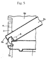
- stopping protrusions 6 are formed, and at the corresponding positions of the bottom wall 1, stopping grooves 7 are formed, and an erect stopping structure of the side walls 2a, 2b, 2c, 2d is formed by these stopping protrusions 6 and stopping grooves 7, and in particular this erect stopping structure is designed to support the engaged state of the stopping protrusions 6 and stopping grooves 7, so that the side walls 2a, 2b, 2c, 2d are held securely in upright position.
- the leading end 6a of the stopping protrusion 6 is horizontal, and the corresponding stopping groove 7 has a horizontal receiving portion 7a. Accordingly, if a load is applied in the push-down direction in the upright position of the side walls 2a, 2b, 2c, 2d, the load is borne by the receiving portions 7a of the stopping grooves 7, so that no load is applied to the pivotal structure of the pivots 4, 4, 5, 5.
- a secure engaged state is maintained so that the side walls 2a, 2b, 2c, 2d may not collapse outward, and by applying a slight impact to the side walls 2a, 2b, 2c, 2d inward from the outside, they can be easily plaited down in a flat state on the bottom wall 1.
- the other pair of side walls 2c, 2d are provided with steps 8 for engaging with the pivoting portions 3 at the both ends, and the pair of side walls 2a, 2b form an erect stopping structure at both ends.
- pawls 9 are formed at both sides of the stopping protrusions 6, and the receiving groove 10 is formed in an upright state of the side walls 2c, 2d.
- the pawls 9 and receiving grooves 10 have flat portions 9a, 10a engaging with each other in an upright state of the side walls 2a, 2b, 2c, 2d as shown in Fig. 6, so that the side walls 2a, 2b, 2c, 2d are held upright in an accurate vertical position.
- the container of the invention To assemble the container of the invention, from the flat plaited state as shown in Fig. 3, first the other pair of side walls 2c, 2d are erected, and then the pair of side walls 2a, 2b are erected, so that a box-shaped container with an open top is formed. That is, when the other pair of side walls 2c, 2d are erected, the stopping protrusions 6 are engaged with the stopping grooves 7, and the steps 8 at both ends are engaged with the pivoting portions 3 so that an upright position is held securely. When the pair of side walls 2a, 2b are erected in succession, the stopping protrusions 6 are engaged with the stopping grooves 7, and the pawls 9 are engaged with the receiving grooves 10, so that an upright position is held securely. Thus, only by erecting the side wall 2a, 2b, 2c, 2d in the instructed sequence, the container can be set up.
- the pair of side walls 2a, 2b are tilted in a state of contacting with the top of the bottom wall 1 by applying a slight impact force inward, and then the other pair of side walls 2c, 2d are similarly tilted, and the pair of side walls 2a, 2b are plaited down on the bottom wall 1, and the other pair of side walls 2c, 2d are plaited down thereon, so as to be in a flat compact form as shown in Fig. 3.
- the container of the embodiment is formed in a hollow double wall structure by blow molding, and a container of a high buffering performance is obtained.
- the invention is not limited to the illustrated embodiment alone, but is realized in various modified or changed modes. That is, in the illustrated embodiment, the bottom wall 1 and the side walls 2a, 2b, 2c, 2d are all in hollow double wall structure, but the object of the invention is similarly achieved if they are formed in a single wall structure.
- the side walls foldable coupled to each side of the bottom wall that is, the pair of confronting side walls and other pair of confronting side walls can be plaited down along the top of the bottom wall, and when not in use, they are plaited down compactly in a size of the bottom wall, so as to be stowed away, stored or carried easily, and when setting up the container, only by erecting the side walls, the upright position is securely held, and the container can be assembled easily and quickly.
Landscapes
- Engineering & Computer Science (AREA)
- Mechanical Engineering (AREA)
- Rigid Containers With Two Or More Constituent Elements (AREA)
- Glass Compositions (AREA)
Abstract
Description
Claims (3)
- A container composing a box-shaped container opened in the top, having side walls tiltably pivoted and coupled to each side of a bottom wall and erecting each side wall, wherein a pair of confronting side walls of the side walls coupled to the sides of the bottom wall are pivoted at the bottom wall side so as to be folded in contact with the top of the bottom wall, and other pair of confronting side walls are pivoted to the bottom wall side so as to be folded in contact with the top of the pair of confronting side walls, and an erect stopping structure consisting of stopping protrusions and stopping grooves is disposed between the pivoting edges of the pair of side walls and other pair of side walls and the corresponding bottom wall position.
- The container of claim 1, wherein other pair of side walls of the side walls are provided also with an erect stopping structure between the pivoting portions at both ends.
- The container of claim 1 or 2 ,wherein the bottom wall and side walls are of hollow double wall structure.
Applications Claiming Priority (3)
| Application Number | Priority Date | Filing Date | Title |
|---|---|---|---|
| JP34127899 | 1999-11-30 | ||
| JP34127899A JP3981226B2 (en) | 1999-11-30 | 1999-11-30 | container |
| PCT/JP2000/008416 WO2001040063A1 (en) | 1999-11-30 | 2000-11-29 | Container |
Publications (3)
| Publication Number | Publication Date |
|---|---|
| EP1253087A1 true EP1253087A1 (en) | 2002-10-30 |
| EP1253087A4 EP1253087A4 (en) | 2004-12-08 |
| EP1253087B1 EP1253087B1 (en) | 2006-06-14 |
Family
ID=18344824
Family Applications (1)
| Application Number | Title | Priority Date | Filing Date |
|---|---|---|---|
| EP00978001A Expired - Lifetime EP1253087B1 (en) | 1999-11-30 | 2000-11-29 | Container |
Country Status (8)
| Country | Link |
|---|---|
| US (1) | US7350661B2 (en) |
| EP (1) | EP1253087B1 (en) |
| JP (1) | JP3981226B2 (en) |
| KR (1) | KR100744678B1 (en) |
| CN (1) | CN1162306C (en) |
| AT (1) | ATE329842T1 (en) |
| DE (1) | DE60028829T2 (en) |
| WO (1) | WO2001040063A1 (en) |
Cited By (6)
| Publication number | Priority date | Publication date | Assignee | Title |
|---|---|---|---|---|
| AU761146B2 (en) * | 1999-09-24 | 2003-05-29 | Advanced Plastic Solutions Pty Ltd | A foldable crate |
| WO2006119513A1 (en) * | 2005-04-29 | 2006-11-09 | Miguel Gonsalves Carreira | A collapsible container |
| WO2007058613A1 (en) * | 2005-11-21 | 2007-05-24 | Molander Tech Ab | A collapsible box |
| EP2085317A1 (en) * | 2008-01-30 | 2009-08-05 | Schoeller Arca Systems GmbH | Thermal container with thermal insulation of goods for transport and storage |
| GB2460079A (en) * | 2008-05-16 | 2009-11-18 | James George Harris | Collapsible storage box |
| ES2357713A1 (en) * | 2008-01-30 | 2011-04-29 | Schoeller Arca Systems Gmbh | Thermal retractable box for transport of fish products and sea foods, has circulating tilting walls arranged around base and each tilting wall is formed at distance from inner wall and external wall |
Families Citing this family (33)
| Publication number | Priority date | Publication date | Assignee | Title |
|---|---|---|---|---|
| US6609744B2 (en) * | 2000-06-29 | 2003-08-26 | Collins & Aikman Products Co. | Collapsible storage apparatus for vehicle cargo compartments |
| US6616003B1 (en) * | 2002-08-09 | 2003-09-09 | King Plast - S.P.A. | Plastic moulded box with compactible structure, of improved type |
| CN1640774B (en) * | 2004-01-18 | 2010-04-28 | 三甲株式会社 | collapsible container |
| CN100480143C (en) * | 2004-01-18 | 2009-04-22 | 三甲株式会社 | Foldable container |
| CN100343128C (en) * | 2004-03-24 | 2007-10-17 | 刘学武 | Foldable turnover packaging box |
| JP4720173B2 (en) * | 2004-12-13 | 2011-07-13 | 株式会社カネカ | Folding synthetic resin foldable container |
| US8152014B2 (en) * | 2005-04-11 | 2012-04-10 | Paul J. Elstone, Sr. | Collapsible container system |
| US20070145052A1 (en) * | 2005-12-28 | 2007-06-28 | Steinhauser Mark R | Collapsible package, and methods |
| US20070256440A1 (en) * | 2006-05-02 | 2007-11-08 | Trotter Spencer S | Collapsible refrigerator |
| US20080251688A1 (en) * | 2007-04-16 | 2008-10-16 | Rajusth Aneela R | Foldable baking pan |
| DE102008007340B4 (en) * | 2008-02-04 | 2011-03-24 | Ifco Systems Gmbh | Folding container fish box for transporting fresh fish |
| TWM344088U (en) * | 2008-05-16 | 2008-11-11 | Young Max Entpr Co Ltd | Foldable storage basket |
| MX2011003888A (en) * | 2008-10-13 | 2011-05-25 | Wabash National Lp | Foldable mobile storage container. |
| DE102009005212A1 (en) * | 2009-01-20 | 2010-07-22 | Schoeller Arca Systems Gmbh | Container for the transport and storage of goods with a container bottom and at least two side panels hinged one above the other |
| JP5497370B2 (en) * | 2009-08-17 | 2014-05-21 | 三菱樹脂株式会社 | Refrigerated container |
| US20110192841A1 (en) * | 2010-02-05 | 2011-08-11 | Standfield Laranard Hunter | Folding trash can |
| KR200465521Y1 (en) | 2011-03-29 | 2013-02-25 | 공간찬넬주식회사 | Container Pallet |
| IN2014CN01812A (en) * | 2011-09-26 | 2015-05-29 | Kyoraku Co Ltd | |
| WO2014022571A1 (en) * | 2012-07-31 | 2014-02-06 | Griggs Billy Joe | Collapsible furniture modules and articles of furniture assembled with the modules |
| US8602240B1 (en) * | 2013-02-04 | 2013-12-10 | Joseph N. Laurita | Method and apparatus for carrier |
| EP2783995B1 (en) * | 2013-03-28 | 2016-06-29 | K. Hartwall Oy AB | Logistics crate module and method of transporting goods |
| KR101311186B1 (en) * | 2013-07-04 | 2013-09-26 | 주식회사 에프엠에스코리아 | Folding type heat insulation box |
| CN104944012B (en) | 2015-05-07 | 2018-02-23 | 上海鸿研物流技术有限公司 | Collapsible container |
| US9555898B2 (en) * | 2015-05-26 | 2017-01-31 | Boost Ideas Llc | Helicopter dolly |
| JP6530682B2 (en) * | 2015-09-11 | 2019-06-12 | 積水化成品工業株式会社 | Synthetic resin folding container |
| CN105501620B (en) * | 2015-12-17 | 2017-09-19 | 探循包装科技(上海)有限公司 | A kind of folding pallet |
| CN105836254B (en) * | 2016-05-24 | 2018-12-07 | 上海鸿研物流技术有限公司 | Folding carton |
| US10155486B2 (en) * | 2016-06-08 | 2018-12-18 | Ford Global Technologies, Llc | Reversible load floor for a motor vehicle |
| US10065763B2 (en) | 2016-09-15 | 2018-09-04 | Arena Packaging, Llc | Wall latching system |
| CN108860917A (en) * | 2018-04-28 | 2018-11-23 | 广东顶创科技股份公司 | Folding box with small occupied space and convenient folding and unfolding |
| CN108502303B (en) * | 2018-06-06 | 2023-12-26 | 东莞市准工自动化机械有限公司 | Circulated folding encapsulation case |
| CN112758471B (en) * | 2021-01-20 | 2022-03-08 | 徐州工业职业技术学院 | Computer transportation safety isolation device convenient to get and put |
| AU2022200628B1 (en) * | 2022-02-01 | 2022-12-08 | K. Hartwall Oy Ab | Container |
Family Cites Families (26)
| Publication number | Priority date | Publication date | Assignee | Title |
|---|---|---|---|---|
| FR2071313A5 (en) * | 1969-12-24 | 1971-09-17 | Baumann Henri | |
| US4020967A (en) * | 1975-09-15 | 1977-05-03 | Hoover Ball And Bearing Company | Collapsible container |
| US4163495A (en) * | 1977-09-21 | 1979-08-07 | Drader Clarence H | Plastic bread carrier having folding end walls |
| CA1246470A (en) * | 1985-06-21 | 1988-12-13 | Andrew Gyenge | Collapsible storage bin |
| JPS6382941A (en) | 1986-09-29 | 1988-04-13 | 昭和電工株式会社 | Folding box |
| JPH02148931A (en) | 1988-11-29 | 1990-06-07 | Nec Corp | Automatic data communication system |
| US4960223A (en) * | 1989-07-18 | 1990-10-02 | Chiang Pei Lieh | Box crate container |
| NO172283C (en) | 1991-02-08 | 1993-06-30 | Norsk Hydro As | ADDITIONAL TRANSPORT BOX |
| DE4201145C2 (en) * | 1992-01-17 | 2001-02-08 | Giso Verwaltungsgmbh & Co Beha | Containers made of plastic, in particular vegetable containers, with foldable side walls |
| US5501351A (en) * | 1992-07-17 | 1996-03-26 | Minnesota Mining And Manufacturing Company | Reusable, multiple-piece storage container |
| US5303823A (en) * | 1992-07-17 | 1994-04-19 | Minnesota Mining And Manufacturing Company | Reusable, two-piece storage container |
| US6131757A (en) * | 1993-08-17 | 2000-10-17 | Clark; Robert A. | Collapsible box |
| US5538153A (en) * | 1993-12-30 | 1996-07-23 | Tetra Laval Holdings & Finance Sa | Folding crate for holding packages |
| JPH0818939A (en) | 1994-07-01 | 1996-01-19 | Ricoh Co Ltd | Image recording device with communication function |
| DE4446322A1 (en) * | 1994-10-07 | 1996-04-11 | Schoeller Plast Ag | Collapsible box-shaped container |
| JP3715678B2 (en) * | 1995-05-22 | 2005-11-09 | 岐阜プラスチック工業株式会社 | Folding container |
| CA2153141C (en) * | 1995-06-30 | 1998-10-06 | Roch Nolet | Five-piece container having foldable side pieces |
| GB9522232D0 (en) * | 1995-10-31 | 1996-01-03 | Woodall Plastic Products Ltd | Collapsible crate |
| US5788103A (en) * | 1996-03-22 | 1998-08-04 | Perstorp Xytec, Inc. | Container base |
| JPH10101067A (en) | 1996-09-30 | 1998-04-21 | Kyoraku Co Ltd | Assembly container |
| JPH10101066A (en) | 1996-09-30 | 1998-04-21 | Kyoraku Co Ltd | Assembly container |
| US6015056A (en) * | 1997-12-19 | 2000-01-18 | Rehrig Pacific Company | Collapsible container |
| US6293418B1 (en) * | 1999-12-09 | 2001-09-25 | Norseman Plastics Limited | Collapsible container |
| US6398054B1 (en) * | 1999-12-27 | 2002-06-04 | Rehrig Pacific Co. | Collapsible container |
| JP3274857B2 (en) * | 2000-04-10 | 2002-04-15 | 岐阜プラスチック工業株式会社 | Folding container |
| US6460717B1 (en) * | 2001-08-29 | 2002-10-08 | Rehrig Pacific Company | Inwardly folding container |
-
1999
- 1999-11-30 JP JP34127899A patent/JP3981226B2/en not_active Expired - Lifetime
-
2000
- 2000-11-29 DE DE60028829T patent/DE60028829T2/en not_active Expired - Lifetime
- 2000-11-29 KR KR1020027005639A patent/KR100744678B1/en not_active Expired - Fee Related
- 2000-11-29 WO PCT/JP2000/008416 patent/WO2001040063A1/en not_active Ceased
- 2000-11-29 EP EP00978001A patent/EP1253087B1/en not_active Expired - Lifetime
- 2000-11-29 US US10/148,657 patent/US7350661B2/en not_active Expired - Fee Related
- 2000-11-29 AT AT00978001T patent/ATE329842T1/en not_active IP Right Cessation
- 2000-11-29 CN CNB008164762A patent/CN1162306C/en not_active Expired - Fee Related
Cited By (7)
| Publication number | Priority date | Publication date | Assignee | Title |
|---|---|---|---|---|
| AU761146B2 (en) * | 1999-09-24 | 2003-05-29 | Advanced Plastic Solutions Pty Ltd | A foldable crate |
| WO2006119513A1 (en) * | 2005-04-29 | 2006-11-09 | Miguel Gonsalves Carreira | A collapsible container |
| WO2007058613A1 (en) * | 2005-11-21 | 2007-05-24 | Molander Tech Ab | A collapsible box |
| EP2085317A1 (en) * | 2008-01-30 | 2009-08-05 | Schoeller Arca Systems GmbH | Thermal container with thermal insulation of goods for transport and storage |
| ES2357713A1 (en) * | 2008-01-30 | 2011-04-29 | Schoeller Arca Systems Gmbh | Thermal retractable box for transport of fish products and sea foods, has circulating tilting walls arranged around base and each tilting wall is formed at distance from inner wall and external wall |
| DE102008006696B4 (en) * | 2008-01-30 | 2015-11-12 | Schoeller Arca Systems Gmbh | Thermo-containers with thermal insulation of goods for transport and storage |
| GB2460079A (en) * | 2008-05-16 | 2009-11-18 | James George Harris | Collapsible storage box |
Also Published As
| Publication number | Publication date |
|---|---|
| JP2001158422A (en) | 2001-06-12 |
| KR100744678B1 (en) | 2007-08-01 |
| EP1253087A4 (en) | 2004-12-08 |
| US7350661B2 (en) | 2008-04-01 |
| DE60028829D1 (en) | 2006-07-27 |
| DE60028829T2 (en) | 2007-05-24 |
| JP3981226B2 (en) | 2007-09-26 |
| EP1253087B1 (en) | 2006-06-14 |
| WO2001040063A1 (en) | 2001-06-07 |
| US20020179601A1 (en) | 2002-12-05 |
| ATE329842T1 (en) | 2006-07-15 |
| CN1402682A (en) | 2003-03-12 |
| CN1162306C (en) | 2004-08-18 |
| KR20020047320A (en) | 2002-06-21 |
Similar Documents
| Publication | Publication Date | Title |
|---|---|---|
| US20020179601A1 (en) | Container | |
| US6863180B2 (en) | Collapsible container | |
| AU737345B2 (en) | Collapsible container | |
| US6405888B1 (en) | Collapsible container | |
| US8651309B2 (en) | Collapsible container | |
| US4854652A (en) | Dual voting booth package | |
| JP2000501049A (en) | box | |
| KR102769611B1 (en) | Portable box with folding structure | |
| JP3726983B2 (en) | Folding storage box | |
| JP2001341736A (en) | Setup container | |
| WO2001051366A1 (en) | Reversibly collapsible/erectable container | |
| JP2014084172A (en) | Foldable container | |
| JP3249804B2 (en) | Folding container | |
| EP1321064A1 (en) | Collapsible storage box | |
| JPH10101066A (en) | Assembly container | |
| WO2002087923A1 (en) | Multi-compartment collapsible structure | |
| JPH11222233A (en) | Built-up container | |
| JP4689069B2 (en) | Folding container | |
| JPS594913Y2 (en) | collapsible container | |
| JPH07309338A (en) | Foldable container | |
| JP4499869B2 (en) | Folding container | |
| JP2004035008A (en) | Container | |
| JP2023025591A (en) | Transportation container and raising frame | |
| KR20230126426A (en) | Folding Box | |
| JPH0676047U (en) | Folding container |
Legal Events
| Date | Code | Title | Description |
|---|---|---|---|
| PUAI | Public reference made under article 153(3) epc to a published international application that has entered the european phase |
Free format text: ORIGINAL CODE: 0009012 |
|
| 17P | Request for examination filed |
Effective date: 20020628 |
|
| AK | Designated contracting states |
Kind code of ref document: A1 Designated state(s): AT BE CH CY DE DK ES FI FR GB GR IE IT LI LU MC NL PT SE TR |
|
| A4 | Supplementary search report drawn up and despatched |
Effective date: 20041022 |
|
| 17Q | First examination report despatched |
Effective date: 20050414 |
|
| GRAP | Despatch of communication of intention to grant a patent |
Free format text: ORIGINAL CODE: EPIDOSNIGR1 |
|
| GRAS | Grant fee paid |
Free format text: ORIGINAL CODE: EPIDOSNIGR3 |
|
| GRAA | (expected) grant |
Free format text: ORIGINAL CODE: 0009210 |
|
| AK | Designated contracting states |
Kind code of ref document: B1 Designated state(s): AT BE CH CY DE DK ES FI FR GB GR IE IT LI LU MC NL PT SE TR |
|
| PG25 | Lapsed in a contracting state [announced via postgrant information from national office to epo] |
Ref country code: IT Free format text: LAPSE BECAUSE OF FAILURE TO SUBMIT A TRANSLATION OF THE DESCRIPTION OR TO PAY THE FEE WITHIN THE PRESCRIBED TIME-LIMIT;WARNING: LAPSES OF ITALIAN PATENTS WITH EFFECTIVE DATE BEFORE 2007 MAY HAVE OCCURRED AT ANY TIME BEFORE 2007. THE CORRECT EFFECTIVE DATE MAY BE DIFFERENT FROM THE ONE RECORDED. Effective date: 20060614 Ref country code: CH Free format text: LAPSE BECAUSE OF FAILURE TO SUBMIT A TRANSLATION OF THE DESCRIPTION OR TO PAY THE FEE WITHIN THE PRESCRIBED TIME-LIMIT Effective date: 20060614 Ref country code: NL Free format text: LAPSE BECAUSE OF FAILURE TO SUBMIT A TRANSLATION OF THE DESCRIPTION OR TO PAY THE FEE WITHIN THE PRESCRIBED TIME-LIMIT Effective date: 20060614 Ref country code: LI Free format text: LAPSE BECAUSE OF FAILURE TO SUBMIT A TRANSLATION OF THE DESCRIPTION OR TO PAY THE FEE WITHIN THE PRESCRIBED TIME-LIMIT Effective date: 20060614 Ref country code: FI Free format text: LAPSE BECAUSE OF FAILURE TO SUBMIT A TRANSLATION OF THE DESCRIPTION OR TO PAY THE FEE WITHIN THE PRESCRIBED TIME-LIMIT Effective date: 20060614 Ref country code: BE Free format text: LAPSE BECAUSE OF FAILURE TO SUBMIT A TRANSLATION OF THE DESCRIPTION OR TO PAY THE FEE WITHIN THE PRESCRIBED TIME-LIMIT Effective date: 20060614 Ref country code: AT Free format text: LAPSE BECAUSE OF FAILURE TO SUBMIT A TRANSLATION OF THE DESCRIPTION OR TO PAY THE FEE WITHIN THE PRESCRIBED TIME-LIMIT Effective date: 20060614 |
|
| REG | Reference to a national code |
Ref country code: GB Ref legal event code: FG4D |
|
| REG | Reference to a national code |
Ref country code: CH Ref legal event code: EP |
|
| REG | Reference to a national code |
Ref country code: IE Ref legal event code: FG4D |
|
| REF | Corresponds to: |
Ref document number: 60028829 Country of ref document: DE Date of ref document: 20060727 Kind code of ref document: P |
|
| PG25 | Lapsed in a contracting state [announced via postgrant information from national office to epo] |
Ref country code: SE Free format text: LAPSE BECAUSE OF FAILURE TO SUBMIT A TRANSLATION OF THE DESCRIPTION OR TO PAY THE FEE WITHIN THE PRESCRIBED TIME-LIMIT Effective date: 20060914 Ref country code: DK Free format text: LAPSE BECAUSE OF FAILURE TO SUBMIT A TRANSLATION OF THE DESCRIPTION OR TO PAY THE FEE WITHIN THE PRESCRIBED TIME-LIMIT Effective date: 20060914 |
|
| PG25 | Lapsed in a contracting state [announced via postgrant information from national office to epo] |
Ref country code: ES Free format text: LAPSE BECAUSE OF FAILURE TO SUBMIT A TRANSLATION OF THE DESCRIPTION OR TO PAY THE FEE WITHIN THE PRESCRIBED TIME-LIMIT Effective date: 20060925 |
|
| PG25 | Lapsed in a contracting state [announced via postgrant information from national office to epo] |
Ref country code: PT Free format text: LAPSE BECAUSE OF FAILURE TO SUBMIT A TRANSLATION OF THE DESCRIPTION OR TO PAY THE FEE WITHIN THE PRESCRIBED TIME-LIMIT Effective date: 20061114 |
|
| PG25 | Lapsed in a contracting state [announced via postgrant information from national office to epo] |
Ref country code: IE Free format text: LAPSE BECAUSE OF NON-PAYMENT OF DUE FEES Effective date: 20061129 |
|
| PG25 | Lapsed in a contracting state [announced via postgrant information from national office to epo] |
Ref country code: MC Free format text: LAPSE BECAUSE OF NON-PAYMENT OF DUE FEES Effective date: 20061130 |
|
| NLV1 | Nl: lapsed or annulled due to failure to fulfill the requirements of art. 29p and 29m of the patents act | ||
| REG | Reference to a national code |
Ref country code: CH Ref legal event code: PL |
|
| PLBE | No opposition filed within time limit |
Free format text: ORIGINAL CODE: 0009261 |
|
| STAA | Information on the status of an ep patent application or granted ep patent |
Free format text: STATUS: NO OPPOSITION FILED WITHIN TIME LIMIT |
|
| EN | Fr: translation not filed | ||
| 26N | No opposition filed |
Effective date: 20070315 |
|
| GBPC | Gb: european patent ceased through non-payment of renewal fee |
Effective date: 20061129 |
|
| PG25 | Lapsed in a contracting state [announced via postgrant information from national office to epo] |
Ref country code: GB Free format text: LAPSE BECAUSE OF NON-PAYMENT OF DUE FEES Effective date: 20061129 |
|
| PG25 | Lapsed in a contracting state [announced via postgrant information from national office to epo] |
Ref country code: GR Free format text: LAPSE BECAUSE OF FAILURE TO SUBMIT A TRANSLATION OF THE DESCRIPTION OR TO PAY THE FEE WITHIN THE PRESCRIBED TIME-LIMIT Effective date: 20060915 Ref country code: FR Free format text: LAPSE BECAUSE OF FAILURE TO SUBMIT A TRANSLATION OF THE DESCRIPTION OR TO PAY THE FEE WITHIN THE PRESCRIBED TIME-LIMIT Effective date: 20070309 |
|
| PG25 | Lapsed in a contracting state [announced via postgrant information from national office to epo] |
Ref country code: LU Free format text: LAPSE BECAUSE OF NON-PAYMENT OF DUE FEES Effective date: 20061129 Ref country code: TR Free format text: LAPSE BECAUSE OF FAILURE TO SUBMIT A TRANSLATION OF THE DESCRIPTION OR TO PAY THE FEE WITHIN THE PRESCRIBED TIME-LIMIT Effective date: 20060614 |
|
| PG25 | Lapsed in a contracting state [announced via postgrant information from national office to epo] |
Ref country code: FR Free format text: LAPSE BECAUSE OF FAILURE TO SUBMIT A TRANSLATION OF THE DESCRIPTION OR TO PAY THE FEE WITHIN THE PRESCRIBED TIME-LIMIT Effective date: 20060614 Ref country code: CY Free format text: LAPSE BECAUSE OF FAILURE TO SUBMIT A TRANSLATION OF THE DESCRIPTION OR TO PAY THE FEE WITHIN THE PRESCRIBED TIME-LIMIT Effective date: 20060614 |
|
| PGFP | Annual fee paid to national office [announced via postgrant information from national office to epo] |
Ref country code: DE Payment date: 20141119 Year of fee payment: 15 |
|
| REG | Reference to a national code |
Ref country code: DE Ref legal event code: R119 Ref document number: 60028829 Country of ref document: DE |
|
| PG25 | Lapsed in a contracting state [announced via postgrant information from national office to epo] |
Ref country code: DE Free format text: LAPSE BECAUSE OF NON-PAYMENT OF DUE FEES Effective date: 20160601 |