EP1253038A2 - Independent suspension system - Google Patents
Independent suspension system Download PDFInfo
- Publication number
- EP1253038A2 EP1253038A2 EP02252734A EP02252734A EP1253038A2 EP 1253038 A2 EP1253038 A2 EP 1253038A2 EP 02252734 A EP02252734 A EP 02252734A EP 02252734 A EP02252734 A EP 02252734A EP 1253038 A2 EP1253038 A2 EP 1253038A2
- Authority
- EP
- European Patent Office
- Prior art keywords
- gear box
- hub
- axis
- suspension system
- independent suspension
- Prior art date
- Legal status (The legal status is an assumption and is not a legal conclusion. Google has not performed a legal analysis and makes no representation as to the accuracy of the status listed.)
- Granted
Links
- 239000000725 suspension Substances 0.000 title claims abstract description 34
- 230000009467 reduction Effects 0.000 claims abstract description 17
- 230000000712 assembly Effects 0.000 claims abstract description 13
- 238000000429 assembly Methods 0.000 claims abstract description 13
- 230000008878 coupling Effects 0.000 description 6
- 238000010168 coupling process Methods 0.000 description 6
- 238000005859 coupling reaction Methods 0.000 description 6
- 230000008901 benefit Effects 0.000 description 4
- 230000004048 modification Effects 0.000 description 2
- 238000012986 modification Methods 0.000 description 2
- 238000004806 packaging method and process Methods 0.000 description 2
- 230000003068 static effect Effects 0.000 description 2
- 239000000969 carrier Substances 0.000 description 1
Images


Classifications
-
- B—PERFORMING OPERATIONS; TRANSPORTING
- B60—VEHICLES IN GENERAL
- B60K—ARRANGEMENT OR MOUNTING OF PROPULSION UNITS OR OF TRANSMISSIONS IN VEHICLES; ARRANGEMENT OR MOUNTING OF PLURAL DIVERSE PRIME-MOVERS IN VEHICLES; AUXILIARY DRIVES FOR VEHICLES; INSTRUMENTATION OR DASHBOARDS FOR VEHICLES; ARRANGEMENTS IN CONNECTION WITH COOLING, AIR INTAKE, GAS EXHAUST OR FUEL SUPPLY OF PROPULSION UNITS IN VEHICLES
- B60K17/00—Arrangement or mounting of transmissions in vehicles
- B60K17/04—Arrangement or mounting of transmissions in vehicles characterised by arrangement, location or kind of gearing
- B60K17/043—Transmission unit disposed in on near the vehicle wheel, or between the differential gear unit and the wheel
-
- B—PERFORMING OPERATIONS; TRANSPORTING
- B60—VEHICLES IN GENERAL
- B60G—VEHICLE SUSPENSION ARRANGEMENTS
- B60G2200/00—Indexing codes relating to suspension types
- B60G2200/10—Independent suspensions
- B60G2200/14—Independent suspensions with lateral arms
- B60G2200/144—Independent suspensions with lateral arms with two lateral arms forming a parallelogram
-
- B—PERFORMING OPERATIONS; TRANSPORTING
- B60—VEHICLES IN GENERAL
- B60G—VEHICLE SUSPENSION ARRANGEMENTS
- B60G2200/00—Indexing codes relating to suspension types
- B60G2200/40—Indexing codes relating to the wheels in the suspensions
- B60G2200/422—Driving wheels or live axles
-
- B—PERFORMING OPERATIONS; TRANSPORTING
- B60—VEHICLES IN GENERAL
- B60G—VEHICLE SUSPENSION ARRANGEMENTS
- B60G2204/00—Indexing codes related to suspensions per se or to auxiliary parts
- B60G2204/10—Mounting of suspension elements
- B60G2204/19—Mounting of transmission differential
-
- B—PERFORMING OPERATIONS; TRANSPORTING
- B60—VEHICLES IN GENERAL
- B60G—VEHICLE SUSPENSION ARRANGEMENTS
- B60G2204/00—Indexing codes related to suspensions per se or to auxiliary parts
- B60G2204/40—Auxiliary suspension parts; Adjustment of suspensions
- B60G2204/419—Gears
- B60G2204/4191—Planetary or epicyclic gears
-
- B—PERFORMING OPERATIONS; TRANSPORTING
- B60—VEHICLES IN GENERAL
- B60G—VEHICLE SUSPENSION ARRANGEMENTS
- B60G2300/00—Indexing codes relating to the type of vehicle
- B60G2300/14—Buses
-
- B—PERFORMING OPERATIONS; TRANSPORTING
- B60—VEHICLES IN GENERAL
- B60G—VEHICLE SUSPENSION ARRANGEMENTS
- B60G2300/00—Indexing codes relating to the type of vehicle
- B60G2300/38—Low or lowerable bed vehicles
-
- B—PERFORMING OPERATIONS; TRANSPORTING
- B60—VEHICLES IN GENERAL
- B60Y—INDEXING SCHEME RELATING TO ASPECTS CROSS-CUTTING VEHICLE TECHNOLOGY
- B60Y2200/00—Type of vehicle
- B60Y2200/10—Road Vehicles
- B60Y2200/14—Trucks; Load vehicles, Busses
- B60Y2200/143—Busses
-
- B—PERFORMING OPERATIONS; TRANSPORTING
- B60—VEHICLES IN GENERAL
- B60Y—INDEXING SCHEME RELATING TO ASPECTS CROSS-CUTTING VEHICLE TECHNOLOGY
- B60Y2200/00—Type of vehicle
- B60Y2200/10—Road Vehicles
- B60Y2200/14—Trucks; Load vehicles, Busses
- B60Y2200/143—Busses
- B60Y2200/1432—Low floor busses
Definitions
- This invention relates to an independent suspension system, and more particularly an independent suspension system for a mass transit vehicle which provides a significantly lower floor profile.
- Mass transit vehicles such as trolley cars, buses, and the like typically have seats aligned at the lateral sides of the vehicle, with a central aisle and floor extending along the vehicle.
- the vehicle floor and aisle positioned relatively low to the ground. This provides faster cycle time if the bus stops and more comfort to all passengers, in special children, elderly and passengers with disabilities.
- Mass transit vehicles typically have several axles which support, drive and steer the vehicle. Many such vehicles provide a rigid axle having a gear box at a longitudinal end to form an inverted portal axle configuration. Disadvantageously, this arrangement necessarily eliminates the ride benefits of independent suspension systems.
- independent suspension systems have been available with either a single reduction carrier on relatively lighter vehicles or a double reduction system on relatively heavier vehicles.
- the reduction carriers are located along the axle centerline in these known independent suspension systems and thus take up a significant amount of packaging space.
- the floor profile must be raised for a significant length of the vehicle. Raising the floor profile in such a manner requires the passengers to climb up to a platform above the axle, which renders that portion of the bus either inaccessible or uncomfortable for people with disabilities.
- the instant invention includes a first and second hub assembly supported by an independent suspension system which allow the independent articulation of each hub assembly.
- the hub assemblies define a first axis substantially transverse to a vehicle longitudinal axis.
- an input gear box is mounted directly to the first hub gear box to provide a torque input thereto.
- the input gear box further includes a coupling extending therefrom to receive an input from a drive source such as vehicle engine.
- the input gear box is mounted offset from the first axis and the vehicle longitudinal axis while simultaneously driving both hub assemblies.
- the coupling and the drive shaft provide input over an angular envelope commensurate with the articulation range of the independent suspension system.
- an input gear box is independently mounted to a second profile segment of the vehicle floor which defines an aisle floor.
- the input gear box is mounted along the vehicle longitudinal axis offset from the first axis.
- the input gear box includes a coupling extending therefrom to receive an input as described above to drive the first and second hub gear boxes through a first and second drive shaft.
- the instant invention thereby provides an independent suspension system which increases the amount of packaging space available underneath the vehicle and allows a lower vehicle floor profile for a significantly greater length of the vehicle.
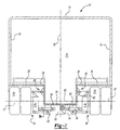
- Figure 1 schematically illustrates a cross-sectional view of a vehicle 10 which includes a passenger compartment 12 defined by a roof 14, two side walls 16, and a vehicle floor 18.
- the cross-sectional view is taken transverse to the vehicle length. That is, substantially along the vehicle width ( Figure 3).
- the vehicle 10 includes a multiple of passenger seats 20 mounted adjacent to each of the side walls 16 with a center aisle 22 extending along the length of the vehicle 10 and between the seats 20. In order to facilitate entering and exiting the vehicle 10, it is desirable to have the vehicle floor 18 and aisle 22 positioned relatively low to the ground.
- the floor 18 defined beneath the passenger seats 20 and the aisle 22 preferably defines a first profile segment.
- the second profile segment 24 defines the floor of the aisle 22 in the axle zone while the third profile segment 26 defines the top of the wheel box.
- the first profile segment 18 defines a support for a passenger seat 20 ( Figure 3).
- the profile segments 18, 24, 26 further define an underside 28 of the vehicle 10.
- a set of vehicle wheels 30,32 are each mounted to an independent suspension system 34 adjacent the vehicle underside 28. It should be understood that vehicle 10 is typically provided with additional axles, driven and/or non-drive axles, and several sets of wheels including (as illustrated in Figure 1) multiple pairs of wheels per axle.
- a first and second hub assembly 34,36 support their respective set of wheels 30,32.
- the hub assemblies 34,36 each define a rotational axis 37 about which the vehicle wheels 30,32 are rotated.
- the hub assemblies 34,36 are each supported by an independent suspension system (illustrated somewhat schematically at 38, 40) which allow the independent articulation of each hub assembly 34,36. It should be realized that although a particular upper and lower suspension link arm configuration is illustrated in the disclosed embodiment, other independent suspension systems will benefit from the instant invention.
- the independent suspension systems 38, 40 are preferably mounted between the second and third profile segments 24, 26 at mounts 43 such that the hub assemblies 34,36 define a first axis 39 substantially transverse to the vehicle longitudinal axis 25.
- the first axis 39 is defined herein at a particular static condition. In this static condition, such as when the vehicle 10 is parked or traveling over level terrain, the rotational axis 37 of both hub assemblies 34,36 are substantially aligned along the first axis 39. It will be appreciated that because of the independent suspension systems 38, 40, the rotational axis 37 of the hub assemblies 34, 36 may be individually displaced from the first axis 39. In other words, each hub assembly 34, 36 is individually articulatable.
- a first hub gear box 42 is operably connected to the first hub assembly 34 for providing torque to drive the first set of wheels 30.
- a second hub gear box 44 which is effectively identical to the first hub gear box 42 is operably connected to the second hub assembly 36 for providing torque to drive the second set of wheels 32.
- the first and second hub gear box 42,44 include a reduction gear set for reducing a rotational input such as preferably a helical gear reduction box.
- an input gear box 46 is mounted directly to the first hub gear box 42 to provide a torque input thereto.
- the input gear box 46 includes a reduction gear set for reducing a rotational input such as preferably a spiral/bevel gear reduction box.
- the input gear box 46 reduction gear set thus directly engages the first gear box 42 reduction gear set.
- the gear sets can include any type of gears known in the art, and can be configured for various reduction gear ratios as is known in the art. Appropriate gear reductions depending upon the drive source is well within the knowledge of one skilled in the art.
- the input gear box further includes a coupling 48 extending therefrom to receive an input from a drive source such as vehicle engine (not shown). Appropriate gear reductions depending upon the drive source is well within the knowledge of one skilled in the art. It should be further understood that additional drive train components may also benefit from the instant invention.
- the input gear box 46 is preferably mounted offset from the first axis 39 and from the vehicle longitudinal axis 25.
- the input gear box 46 includes a gear set which engages the first hub gear box 42 offset from the rotational axis 37 of the first hub gear box 42.
- the input gear box 46 is further connected to the second hub gear box 44 through a drive shaft 50 such as a constant velocity joint.
- the input gear box 46 thus simultaneously drives both hub assemblies 34,36 to provide a rotation input thereto. It should be understood that the coupling 48 and the drive shaft 50 provide input over an angular envelope commensurate with the articulation range of the independent suspension systems 38,40.
- An input gear box 52 is independently mounted to the second profile segment 24 which defines the floor of the aisle 22.
- the input gear box 52 is preferably mounted along the vehicle longitudinal axis 25 offset from the first axis 39.
- the input gear box 52 includes a coupling 54 extending therefrom to receive an input as described above.
- the input gear box 52 is connected to the first and second hub gear boxes 42, 44 through a first and second drive shaft 56,58 such as a constant velocity joint.
- the input gear box 52 thus simultaneously drives both hub assemblies 34,36 to provide a rotation input thereto through the drive shafts 56, 58.
Landscapes
- Engineering & Computer Science (AREA)
- Chemical & Material Sciences (AREA)
- Combustion & Propulsion (AREA)
- Transportation (AREA)
- Mechanical Engineering (AREA)
- Vehicle Body Suspensions (AREA)
Abstract
Description
Claims (12)
- A vehicle independent suspension system (38, 40) comprising:first and a second hub assembly (34, 36), said first and second hub assembly having a rotational axis defining along a first axis (39), said first axis substantially transverse to a vehicle longitudinal axis (25);independent suspension system independently supporting each of said first and second hub assemblies;first hub gear box (42) operably connected to said first hub assembly for providing torque to drive said first hub assembly;second hub gear box (44) operably connected to said second hub assembly for providing torque to drive said second hub assembly; andinput gear box (46) offset from said first axis, said input gear box operably connected to said first and second hub gear box for providing torque thereto.
- A vehicle independent suspension system as recited in Claim 1 further including a constant velocity drive shaft interconnecting said input gear box and said first and second hub gear box.
- A vehicle independent suspension system as recited in Claim 2 wherein said constant velocity drive shaft is offset from said first axis.
- A vehicle independent suspension system as recited in Claim 1 wherein said input gear box is mounted directly to said first hub gear box, and a constant velocity drive shaft interconnecting said input gear box and said second hub gear box.
- A vehicle independent suspension system as recited in Claim 4 wherein said constant velocity drive shaft is offset from said first axis
- A vehicle independent suspension system (38, 40) comprising:a first and a second hub assembly (34, 36), said first and second hub assembly having a rotational axis defining along a first axis (39) , said first axis substantially transverse to a vehicle longitudinal axis (25);an independent suspension system independently supporting each of said first and second hub assemblies;a first hub gear box (42) operably connected to said first hub assembly for providing torque to drive said first hub assembly;a second hub gear box (44) operably connected to said second hub assembly for providing torque to drive said second hub assembly;an input gear box (46) mounted to said first hub gear box and offset from said first axis and laterally offset from a vehicle longitudinal axis, said input gear box operably connected directly to said first hub gear box for providing torque thereto; anda constant velocity drive shaft interconnecting said input gear box and said second hub gear box for providing torque thereto, said constant velocity drive shaft offset from said first axis.
- A vehicle independent suspension system (38, 46) comprising:a first and a second hub assembly (34, 36), said first and second hub assembly having a rotational axis defining along a first axis (39), said first axis substantially transverse to a vehicle longitudinal axis (25);an independent suspension system independently supporting each of said first and second hub assemblies;a first hub gear box (42) operably connected to said first hub assembly for providing torque to drive said first hub assembly;a second hub gear box (44) operably connected to said second hub assembly for providing torque to drive said second hub assembly;an input gear box (52) mounted along a vehicle longitudinal axis, said input gear box offset from said first axis;a first constant velocity drive shaft (56) interconnecting said input gear box and said first hub gear box for providing torque thereto, said first constant velocity drive shaft offset from said first axis; anda second constant velocity drive shaft (58) interconnecting said input gear box and said second hub gear box for providing torque thereto, said second constant velocity drive shaft offset from said first axis.
- A vehicle independent suspension system as recited in any preceding claim wherein said input gear box and/or said first and second hub gearbox includes a reduction gear set for reducing a rotational input.
- A vehicle independent suspension system as recited in Claim 8 wherein said input gear box includes a spiral/bevel gear reduction box.
- A vehicle independent suspension system as recited in Claim 8 or 9 wherein said first and second hub gear box includes a helical gear reduction box.
- A vehicle independent suspension system as recited in any preceding claim further including a floor (18) defined beneath a set of passenger seats (20), said floor having a profile with at least three profile segments wherein a first profile segment (22) extends under the seats and along a vehicle longitudinal axis (25) for a first length and a second profile segment (24) which extends along said longitudinal axis for a second length adjacent to said first axis and a third profile segment (26) above a wheel box, said third profile segment, further from said input gear box than said second profile segment, said independent suspension system attached substantially between said second and third profile segment.
- A vehicle independent suspension system as recited in Claim 10 wherein said input gear box is mounted to said second profile segment.
Applications Claiming Priority (2)
| Application Number | Priority Date | Filing Date | Title |
|---|---|---|---|
| US841343 | 1992-02-25 | ||
| US09/841,343 US6871723B2 (en) | 2001-04-24 | 2001-04-24 | Independent suspension system for a low floor vehicle |
Publications (3)
| Publication Number | Publication Date |
|---|---|
| EP1253038A2 true EP1253038A2 (en) | 2002-10-30 |
| EP1253038A3 EP1253038A3 (en) | 2005-09-28 |
| EP1253038B1 EP1253038B1 (en) | 2008-10-01 |
Family
ID=25284624
Family Applications (1)
| Application Number | Title | Priority Date | Filing Date |
|---|---|---|---|
| EP02252734A Expired - Lifetime EP1253038B1 (en) | 2001-04-24 | 2002-04-18 | Independent suspension system |
Country Status (4)
| Country | Link |
|---|---|
| US (1) | US6871723B2 (en) |
| EP (1) | EP1253038B1 (en) |
| DE (1) | DE60229081D1 (en) |
| ES (1) | ES2312526T3 (en) |
Cited By (2)
| Publication number | Priority date | Publication date | Assignee | Title |
|---|---|---|---|---|
| EP1418068A1 (en) * | 2002-11-08 | 2004-05-12 | Terberg Techniek B.V. | Vehicle with improved cargo space |
| EP1348587A3 (en) * | 2002-03-27 | 2005-09-28 | ArvinMeritor Technology, LLC | A suspension system for a low floor vehicle |
Families Citing this family (9)
| Publication number | Priority date | Publication date | Assignee | Title |
|---|---|---|---|---|
| US6398251B1 (en) | 1997-01-31 | 2002-06-04 | Dallas Smith Corporation | Axleless vehicle suspension system |
| US6986519B2 (en) | 1997-01-31 | 2006-01-17 | Aloha, Llc | Low profile chassis and suspension |
| US7559400B2 (en) | 1997-01-31 | 2009-07-14 | Aloha, Llc | Low profile chassis and suspension |
| US7051833B2 (en) * | 2003-08-22 | 2006-05-30 | Zf Friedrichshafen Ag | Gantry axle |
| US7048087B2 (en) * | 2003-08-26 | 2006-05-23 | Arvinmeritor Technology, Llc | External shaft low floor drive axle assembly |
| WO2005039900A2 (en) * | 2003-10-24 | 2005-05-06 | Aloha, Llc | Suspensions for low floor vehicles |
| US8042869B2 (en) * | 2007-07-13 | 2011-10-25 | Kids Ii, Inc. | Child seat liner |
| CA2714255A1 (en) | 2009-09-01 | 2011-03-01 | Timbren Industries Inc. | Suspension mechanism |
| CN106741187A (en) * | 2016-12-27 | 2017-05-31 | 深圳市沃特玛电池有限公司 | Electric motor coach |
Family Cites Families (21)
| Publication number | Priority date | Publication date | Assignee | Title |
|---|---|---|---|---|
| US502313A (en) | 1893-08-01 | Joshua l | ||
| US2589863A (en) | 1946-12-06 | 1952-03-18 | Orpheus F Quartullo | Gasoline-electric drive for vehicles |
| FR940078A (en) * | 1947-01-10 | 1948-12-02 | Suspension by independent wheels of motor cars and device for transmitting movement to these wheels | |
| DE1895981U (en) * | 1964-02-15 | 1964-07-02 | Rheinstahl Huettenwerke Ag | AXLE FOR OFF-ROAD VEHICLES OD. DGL. |
| FR2339509A2 (en) * | 1975-01-22 | 1977-08-26 | Durand Francois | Motor vehicle transmission system - has engine mounted at side of vehicle, with rear wheel at opposite side driven through converting gears and propellor shafts |
| US4362221A (en) * | 1978-01-19 | 1982-12-07 | Manning Donald L | Vehicle drive wheel suspension |
| DE2835865C2 (en) * | 1978-08-16 | 1986-11-27 | Hermann Dr.-Ing. 3302 Cremlingen Klaue | Motor vehicle |
| DE3136305A1 (en) * | 1981-09-12 | 1983-03-24 | Hermann Dr.-Ing. 7412 Eningen Klaue | Drive axle for heavy motor vehicles |
| JPS59160623A (en) * | 1984-02-16 | 1984-09-11 | Kubota Ltd | Rear wheel drive structure of agricultural tractor |
| WO1990011905A1 (en) | 1989-03-31 | 1990-10-18 | Kabushiki Kaisha Shikoku Sogo Kenkyujo | Electric car |
| DE4112624C1 (en) | 1991-04-18 | 1992-10-01 | Man Nutzfahrzeuge Ag, 8000 Muenchen, De | |
| IT1255575B (en) * | 1992-07-10 | 1995-11-09 | TRANSVERSAL MINIMUM SIZE SUSPENSION, IN PARTICULAR FOR LOW-FLOOR VEHICLES. | |
| HU9203746D0 (en) * | 1992-11-27 | 1993-03-29 | Magyar Vagon Es Gepgyar | Portal type undercarriage with suspension integrated onto housing of drive |
| DE4336672A1 (en) * | 1993-10-27 | 1995-05-04 | Zahnradfabrik Friedrichshafen | Independent suspension |
| US5878830A (en) | 1997-02-18 | 1999-03-09 | Meritor Heavy Vehicle Systems, Llc. | Space saving mounting for electrically driven vehicle wheels |
| US5924504A (en) | 1997-02-18 | 1999-07-20 | Meritor Heavy Vehicle Systems, Llc | Suspension drive unit assembly for an electrically driven vehicle |
| US5931255A (en) * | 1997-05-09 | 1999-08-03 | Caterpillar Inc. | Power transfer arrangement for a machine |
| US6095005A (en) * | 1998-10-15 | 2000-08-01 | Ford Motor Company | Axle drivetrain having speed reduction gear unit for automotive vehicles |
| US6193007B1 (en) * | 1999-08-06 | 2001-02-27 | Mohinder Kumra | Rear suspension and drive axle assembly |
| JP2001270312A (en) * | 2000-03-28 | 2001-10-02 | Hino Motors Ltd | Front suspension structure |
| DE10057090A1 (en) * | 2000-11-17 | 2002-05-23 | Zahnradfabrik Friedrichshafen | portal axis |
-
2001
- 2001-04-24 US US09/841,343 patent/US6871723B2/en not_active Expired - Lifetime
-
2002
- 2002-04-18 DE DE60229081T patent/DE60229081D1/en not_active Expired - Lifetime
- 2002-04-18 ES ES02252734T patent/ES2312526T3/en not_active Expired - Lifetime
- 2002-04-18 EP EP02252734A patent/EP1253038B1/en not_active Expired - Lifetime
Non-Patent Citations (1)
| Title |
|---|
| None |
Cited By (2)
| Publication number | Priority date | Publication date | Assignee | Title |
|---|---|---|---|---|
| EP1348587A3 (en) * | 2002-03-27 | 2005-09-28 | ArvinMeritor Technology, LLC | A suspension system for a low floor vehicle |
| EP1418068A1 (en) * | 2002-11-08 | 2004-05-12 | Terberg Techniek B.V. | Vehicle with improved cargo space |
Also Published As
| Publication number | Publication date |
|---|---|
| US6871723B2 (en) | 2005-03-29 |
| EP1253038A3 (en) | 2005-09-28 |
| DE60229081D1 (en) | 2008-11-13 |
| US20020153690A1 (en) | 2002-10-24 |
| ES2312526T3 (en) | 2009-03-01 |
| EP1253038B1 (en) | 2008-10-01 |
Similar Documents
| Publication | Publication Date | Title |
|---|---|---|
| US6431298B1 (en) | Drive unit assembly for an electrically driven vehicle | |
| US7866423B2 (en) | Low floor drive unit assembly for an electrically driven vehicle | |
| EP1391340B1 (en) | Vehicle gear assembly | |
| US4867072A (en) | Multi-unit rail vehicle for commuter traffic | |
| EP1101643B1 (en) | Low floor drive unit assembly for an electrically driven vehicle | |
| US6871723B2 (en) | Independent suspension system for a low floor vehicle | |
| US20010011611A1 (en) | Chasis for commercial vehicles | |
| US6793035B2 (en) | Semi-independent swing arm suspension system for a low floor vehicle | |
| US20030010561A1 (en) | Low load floor motor vehicle | |
| US20070186803A1 (en) | Axle for rail vehicle having a low-level floor, bogie and corresponding rail vehicle | |
| US7232004B2 (en) | Low load floor motor vehicle | |
| HU208653B (en) | Vehicle particularly railwayh vehicle | |
| US6772698B2 (en) | Articulated train having a low-floor section | |
| US20030137121A1 (en) | Offset axle | |
| US6193007B1 (en) | Rear suspension and drive axle assembly | |
| EP1620276B1 (en) | Inverted portal axle configuration for a low floor vehicule | |
| EP1348587A2 (en) | A suspension system for a low floor vehicle | |
| US20030122340A1 (en) | Independent suspension for low profile vehicles | |
| EP2075175A1 (en) | Urban transport vehicle with small wheels | |
| US6659217B2 (en) | Drive assembly for low floor vehicle | |
| US1475330A (en) | Vehicle pbame | |
| GB2319008A (en) | Drive arrangement for all-wheel drive vehicles with at least three axles | |
| SU812637A1 (en) | Urban bus | |
| JPS591876Y2 (en) | Railway vehicle bogie | |
| JPS6157427A (en) | Mid-ship type car |
Legal Events
| Date | Code | Title | Description |
|---|---|---|---|
| PUAI | Public reference made under article 153(3) epc to a published international application that has entered the european phase |
Free format text: ORIGINAL CODE: 0009012 |
|
| AK | Designated contracting states |
Kind code of ref document: A2 Designated state(s): AT BE CH CY DE DK ES FI FR GB GR IE IT LI LU MC NL PT SE TR |
|
| AX | Request for extension of the european patent |
Free format text: AL;LT;LV;MK;RO;SI |
|
| RAP1 | Party data changed (applicant data changed or rights of an application transferred) |
Owner name: ARVINMERITOR TECHNOLOGY, LLC |
|
| PUAL | Search report despatched |
Free format text: ORIGINAL CODE: 0009013 |
|
| AK | Designated contracting states |
Kind code of ref document: A3 Designated state(s): AT BE CH CY DE DK ES FI FR GB GR IE IT LI LU MC NL PT SE TR |
|
| AX | Request for extension of the european patent |
Extension state: AL LT LV MK RO SI |
|
| 17P | Request for examination filed |
Effective date: 20060303 |
|
| AKX | Designation fees paid |
Designated state(s): DE ES FR GB IT |
|
| 17Q | First examination report despatched |
Effective date: 20061213 |
|
| GRAP | Despatch of communication of intention to grant a patent |
Free format text: ORIGINAL CODE: EPIDOSNIGR1 |
|
| GRAS | Grant fee paid |
Free format text: ORIGINAL CODE: EPIDOSNIGR3 |
|
| GRAA | (expected) grant |
Free format text: ORIGINAL CODE: 0009210 |
|
| AK | Designated contracting states |
Kind code of ref document: B1 Designated state(s): DE ES FR GB IT |
|
| REG | Reference to a national code |
Ref country code: GB Ref legal event code: FG4D |
|
| REF | Corresponds to: |
Ref document number: 60229081 Country of ref document: DE Date of ref document: 20081113 Kind code of ref document: P |
|
| REG | Reference to a national code |
Ref country code: ES Ref legal event code: FG2A Ref document number: 2312526 Country of ref document: ES Kind code of ref document: T3 |
|
| PLBE | No opposition filed within time limit |
Free format text: ORIGINAL CODE: 0009261 |
|
| STAA | Information on the status of an ep patent application or granted ep patent |
Free format text: STATUS: NO OPPOSITION FILED WITHIN TIME LIMIT |
|
| 26N | No opposition filed |
Effective date: 20090702 |
|
| PGFP | Annual fee paid to national office [announced via postgrant information from national office to epo] |
Ref country code: ES Payment date: 20120510 Year of fee payment: 11 |
|
| PGFP | Annual fee paid to national office [announced via postgrant information from national office to epo] |
Ref country code: DE Payment date: 20130515 Year of fee payment: 12 Ref country code: GB Payment date: 20130417 Year of fee payment: 12 |
|
| PGFP | Annual fee paid to national office [announced via postgrant information from national office to epo] |
Ref country code: FR Payment date: 20130625 Year of fee payment: 12 Ref country code: IT Payment date: 20130422 Year of fee payment: 12 |
|
| REG | Reference to a national code |
Ref country code: DE Ref legal event code: R119 Ref document number: 60229081 Country of ref document: DE |
|
| GBPC | Gb: european patent ceased through non-payment of renewal fee |
Effective date: 20140418 |
|
| REG | Reference to a national code |
Ref country code: DE Ref legal event code: R119 Ref document number: 60229081 Country of ref document: DE Effective date: 20141101 |
|
| REG | Reference to a national code |
Ref country code: FR Ref legal event code: ST Effective date: 20141231 |
|
| PG25 | Lapsed in a contracting state [announced via postgrant information from national office to epo] |
Ref country code: DE Free format text: LAPSE BECAUSE OF NON-PAYMENT OF DUE FEES Effective date: 20141101 Ref country code: GB Free format text: LAPSE BECAUSE OF NON-PAYMENT OF DUE FEES Effective date: 20140418 |
|
| PG25 | Lapsed in a contracting state [announced via postgrant information from national office to epo] |
Ref country code: FR Free format text: LAPSE BECAUSE OF NON-PAYMENT OF DUE FEES Effective date: 20140430 |
|
| PG25 | Lapsed in a contracting state [announced via postgrant information from national office to epo] |
Ref country code: IT Free format text: LAPSE BECAUSE OF NON-PAYMENT OF DUE FEES Effective date: 20140418 |
|
| REG | Reference to a national code |
Ref country code: ES Ref legal event code: FD2A Effective date: 20150528 |
|
| PG25 | Lapsed in a contracting state [announced via postgrant information from national office to epo] |
Ref country code: ES Free format text: LAPSE BECAUSE OF NON-PAYMENT OF DUE FEES Effective date: 20140419 |