EP1251416A1 - Diagnose-Einrichtung für einen Feldbus mit steuerungsunabhängiger Informationsübermittlung - Google Patents
Diagnose-Einrichtung für einen Feldbus mit steuerungsunabhängiger Informationsübermittlung Download PDFInfo
- Publication number
- EP1251416A1 EP1251416A1 EP02002510A EP02002510A EP1251416A1 EP 1251416 A1 EP1251416 A1 EP 1251416A1 EP 02002510 A EP02002510 A EP 02002510A EP 02002510 A EP02002510 A EP 02002510A EP 1251416 A1 EP1251416 A1 EP 1251416A1
- Authority
- EP
- European Patent Office
- Prior art keywords
- diagnostic
- application
- plc
- diagnostic device
- fieldbus
- Prior art date
- Legal status (The legal status is an assumption and is not a legal conclusion. Google has not performed a legal analysis and makes no representation as to the accuracy of the status listed.)
- Granted
Links
- 238000012546 transfer Methods 0.000 title description 3
- 230000005540 biological transmission Effects 0.000 claims abstract description 12
- 238000012800 visualization Methods 0.000 claims description 27
- 238000012545 processing Methods 0.000 claims description 4
- 230000001419 dependent effect Effects 0.000 claims 1
- 101100408464 Caenorhabditis elegans plc-1 gene Proteins 0.000 description 5
- 230000002093 peripheral effect Effects 0.000 description 3
- 238000003745 diagnosis Methods 0.000 description 2
- 238000004886 process control Methods 0.000 description 2
- 230000006978 adaptation Effects 0.000 description 1
- 230000008878 coupling Effects 0.000 description 1
- 238000010168 coupling process Methods 0.000 description 1
- 238000005859 coupling reaction Methods 0.000 description 1
- 238000005516 engineering process Methods 0.000 description 1
- 238000011156 evaluation Methods 0.000 description 1
- 239000000284 extract Substances 0.000 description 1
- 230000004807 localization Effects 0.000 description 1
- 230000007774 longterm Effects 0.000 description 1
- 238000012423 maintenance Methods 0.000 description 1
- 238000012544 monitoring process Methods 0.000 description 1
- 230000000750 progressive effect Effects 0.000 description 1
- 230000032258 transport Effects 0.000 description 1
Images


Classifications
-
- G—PHYSICS
- G05—CONTROLLING; REGULATING
- G05B—CONTROL OR REGULATING SYSTEMS IN GENERAL; FUNCTIONAL ELEMENTS OF SUCH SYSTEMS; MONITORING OR TESTING ARRANGEMENTS FOR SUCH SYSTEMS OR ELEMENTS
- G05B23/00—Testing or monitoring of control systems or parts thereof
- G05B23/02—Electric testing or monitoring
- G05B23/0205—Electric testing or monitoring by means of a monitoring system capable of detecting and responding to faults
- G05B23/0259—Electric testing or monitoring by means of a monitoring system capable of detecting and responding to faults characterized by the response to fault detection
- G05B23/0267—Fault communication, e.g. human machine interface [HMI]
- G05B23/027—Alarm generation, e.g. communication protocol; Forms of alarm
Definitions
- the invention relates to a diagnostic device for a fieldbus, which is fieldbus-specific Diagnostic information and parameters, as well as extracts Information about peripheral properties on a Outputs display device for display and evaluation.
- Diagnostic device fulfills the task of diagnostic data for a fieldbus as plain text message or for example as a histogram for long-term analysis as visualized Provide representation.
- the content is Localization of fault locations in sporadically occurring Transmission errors, monitoring the line quality of FO routes and messages from bus modules via their Peripheral faults are displayed.
- the crucial disadvantage is that the logical and physical connection between the fieldbus controller board and the diagnostic device via a dedicated one Interface connection between the fieldbus controller board and PC with diagnostic device, for example Ethernet or V24.
- the diagnostic facility as an ActiveX software component integrated into a visualization application. Since the Data transmission of the diagnostic data from the fieldbus to Diagnostic device no longer carried out via control is an additional interface connection for this necessary.
- DE 100 08 020 A1 discloses a diagnostic device in a process control system known. But here only Measured and control variables from the application monitored and in the Measures taken in the event of a fault or reported.
- the diagnostic device is in DE 100 08 020 A1 Part of the control device since the execution the control program from the diagnostic device being affected.
- the one described here Diagnostic device has the major disadvantage that they do not monitor the function of a fieldbus or Process control network.
- the invention has for its object a diagnostic device to create which in a parent Application can be inserted, for example as ActiveX component with the standardized Software interface.
- the parent application can a visualization of the control application or a Visualization at the management level.
- the diagnostic facility receives the diagnostic data for the fieldbus the fieldbus controller board. The transfer of the
- Diagnostic data is carried out via the PLC I / O bus and in the PLC existing interface. Both the Control application as well as the visualization application are from the transmission of the diagnostic data for the Fieldbus not affected and allowed to program and application are not taken into account. As for the Transmission of the diagnostic data between the fieldbus controller board and the diagnostic device none additional interface connection is provided the internal PLC I / O bus, the external interface of the PLC and the external interface used in the PC.
- the invention Diagnostic device for a fieldbus is one Software component, which in a parent Application via a standardized software interface is integrated and can be started from.
- the diagnostic device is included as an ActiveX component the intended standardized Software interface implemented.
- ActiveX component With ActiveX component becomes an integrable into a main application Software component with a standardized Software interface referred to the main application.
- the ActiveX component is started before or during the Main application runtime added to this.
- the data transmission of the diagnostic data from the external Interface of the PC to the diagnostic device within of the PC carries out the interface on the PC.
- the diagnostic data is transmitted from the Fieldbus interface module for the external interface of the PLC via the interface in the PLC.
- the PLC are for the control application no adjustments or Programming for the operation of the diagnostic device necessary.
- the visualization application on the PC are for the transmission of data for the operation of the Diagnostic device no diagnostic data necessary Adjustments or programming necessary.
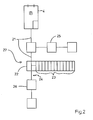
- Fig. 1 shows the diagnostic device according to the invention for a fieldbus that contains the diagnostic information via receives the external interface available in the PLC
- Fig. 3 shows a diagnostic device for a Fieldbus, as it is already known as the state of the art is.
- the diagnostic device 11 is activated in the display device 10 , which receives diagnostic data relating to the fieldbus for further processing or for the display output. Interfaces 2, 12 ensure the corresponding data assignment so that the diagnosis data can be transmitted from the fieldbus interface module 4 to the diagnosis device 11 without adaptation or programming of the control application or visualization application.
- the diagnostic device is operated from the visualization application via the software interface 28 , and feedback from the diagnostic device 11 also takes place via this software interface 28 to the visualization application 10.
- the transmission of the diagnostic information from the fieldbus interface module 4 to the diagnostic device 11 is described below.
- the diagnostic information relating to the fieldbus held in the fieldbus interface module 4 is transmitted via the PLC I / O bus 6 to the interface in the PLC 2 .
- the connection 14 for the diagnostic information between the fieldbus interface module 4 and the PLC I / O bus 6 is adapted for the PLC I / O bus 6 and can also have only a logical character.
- Both I / O data and diagnostic information for the fieldbus are transmitted to the interface in the PLC 2 via the PLC I / O bus 6 .
- the interface in the PLC 2 switches the logical connections.
- the diagnostic information is sent to the external interface of the PLC 7 .
- the I / O data are routed to the control application 3 via the internal logical connection 25 .
- Visualization information comes from the control application 3 via the internal logical connection 16 to the interface of the PLC 2, which forwards it to the external interface 7 of the PLC 1 .
- the external interface 7 of the PLC 1 can be a V24 interface or an Ethernet interface or an interface for another type of transmission, such as parallel transmission.
- the visualization information and diagnostic information for the fieldbus are received via the external interface 17 in the PC 10 .
- the interface 12 in the PC 10 directs the received information according to its affiliation either to the visualization application 13 or to the diagnostic device 11 .
- Visualization information is routed to the visualization application 13 , diagnostic information is routed via the internal logical channel 15 to the diagnostic device 11 .
- the visualization application 13 is not affected in its functional property. All logical connections are also switched in the opposite direction, so that commands and parameters can be transmitted from the diagnostic device 11 to the fieldbus interface module 4 via the data connection 18 and the PLC I / O bus 6 . From the visualization application 13 , parameters or programs for the control application 3 can be transmitted to the PLC 1 via the data connection 18 .
- the application 13 on the PC can of course also be a programming application for the PLC or a configuration application or programming application for the fieldbus.
- the interface 12 in the PC 10 can consist of a software-programmable data processing unit or of a component executed in hardware.
- a diagnostic tool 21 shows a diagnostic tool 21 as it receives its diagnostic information in a known manner.
- a specially provided physical connection 19 transports the diagnostic information to the diagnostic device 11.
- commands and parameters for bus operation can be sent from the diagnostic device 11 to the fieldbus interface module 4 .
- the SPS.I / O bus 6 contains only I / O data, so that the control application 3 can receive this data directly.
- Via the data connection 20 between the interfaces 7 and 17 only visualization information or other control-specific data are transmitted by the control application 3 , and in the opposite direction, only control-specific parameters or programs for the control application 3 are transmitted by the visualization application 13 .
Landscapes
- Engineering & Computer Science (AREA)
- Human Computer Interaction (AREA)
- Physics & Mathematics (AREA)
- General Physics & Mathematics (AREA)
- Automation & Control Theory (AREA)
- Testing And Monitoring For Control Systems (AREA)
- Programmable Controllers (AREA)
Abstract
Description
In der Anzeigevorrichtung 10 mit der Visualisierungsanwendung 13 werden die über die externe Schnittstelle 17 im PC 10 Visualisierungsinformationen und Diagnoseinformationen für den Feldbus empfangen. Das Interface 12 im PC 10 lenkt die empfangenen Informationen ihrer Zugehörigkeit entsprechend entweder an die Visualisierungsanwendung 13 oder an die Diagnose-Einrichtung 11 weiter. Visualisierungsinformationen werden zur Visualisierungsanwendung 13 geleitet, Diagnoseinformationen werden über den internen logischen Kanal 15 zur Diagnose-Einrichtung 11 geleitet. Die Visualisierungsanwendung 13 wird dabei in seiner funktionalen Eigenschaft nicht beeinflußt. Das Schalten aller logischen Verbindungen geschieht in umgekehrter Richtung ebenfalls, so daß aus der Diagnose-Einrichtung 11 an die Feldbus-Anschaltbaugruppe 4 Befehle und Parameter über die Datenverbindung 18 und dem SPS-I/O-Bus 6 übertragen werden können. Aus der Visualisierungsanwendung 13 können Parameter oder Programme für die Steuerungs-Anwendung 3 zur SPS 1 über die Datenverbindung 18 übertragen werden. Selbstverständlich kann die Anwendung 13 auf dem PC auch eine Programmieranwendung für die SPS oder eine Konfigurationsanwendung oder Programmieranwendung für den Feldbus sein. Das Interface 12 im PC 10 kann aus einer Software-programmierbaren Datenverarbeitungseinheit oder aus einer in Hardware ausgeführten Komponente bestehen.
Claims (10)
- Diagnose-Einrichtung (11) für einen Feldbus (27), welches feldbusspezifische Informationen wie beispielsweise Einzel-Übertragungsfehler, dauernd anstehende Unterbrechung mit Ortsangabe, Leitungsqualität von LWL-Strecken, sowie weitere für den Feldbus relevanten Diagnose-Informationen zur Anzeige auf einer Anzeigevorrichtung (10) ausgibt,
dadurch gekennzeichnet, dass die Diagnose-Informationen von der Feldbus-Anschaltbaugruppe (4) über den internen Bus (6) der SPS oder SPS-Erweiterungsbus (6)zur externen Schnittstelle (7) der SPS (1) geführt werden, ohne daß die Steuerungs-Anwendung (3) beeinflußt wird. - Diagnose-Einrichtung nach Anspruch 1,
dadurch gekennzeichnet, dass die Steuerungs-Anwendung (3) in der Programmierungsphase keine von der Diagnose-Einrichtung (11) abhängigen Programmierungen benötigt. - Diagnose-Einrichtung nach Anspruch 1 bis 2,
dadurch gekennzeichnet, dass das Durchleiten der Diagnose-Informationen innerhalb der SPS (1) das Interface (2) der SPS (1) vornimmt, welches aus einer Software-programmierbaren Datenverarbeitungseinheit besteht. - Diagnose-Einrichtung nach Anspruch 1 bis 2,
dadurch gekennzeichnet, dass das Durchleiten der Diagnose-Informationen innerhalb der SPS (1) das Interface (2) der SPS (1) vornimmt, welches aus einer für diese Anwendung erstellte Hardware-Komponente besteht. - Diagnose-Einrichtung nach einem der vorherigen Ansprüche
dadurch gekennzeichnet, dass auf der Anzeigevorrichtung (10) ein Interface (12) die logische Aufteilung der zu übertragenden Informationen vornimmt, wobei die Diagnoseinformationen zur Diagnose-Einrichtung (11) übermittelt werden und die für die Visualisierungsoder Programmieranwendung vorgesehenen Informationen zur Visualisierungs- oder Programmieranwendung (13) übermittelt werden. - Diagnose-Einrichtung nach Anspruch 5,
dadurch gekennzeichnet, dass die Diagnose-Einrichtung (11) als Active-X Komponente in eine bestehende Anwendung (13) auf der Anzeigevorrichtung (10) eingebunden ist. - Diagnose-Einrichtung nach Anspruch 5 oder 6,
dadurch gekennzeichnet, daß die Diagnose-Einrichtung (11) die Diagnoseinformationen aus der Visualisierungsanwendung heraus über eine standardisierte Schnittstelle für ActiveX-Komponenten erhält. - Diagnose-Einrichtung nach Anspruch 5 oder 6,
dadurch gekennzeichnet, dass die bestehende Anwendung (13) auf der Anzeigevorrichtung (10) eine Visualisierungsanwendung (13) ist. - Diagnose-Einrichtung nach Anspruch 5 oder 6,
dadurch gekennzeichnet, dass die bestehende Anwendung (13) auf der Anzeigevorrichtung (10) eine Programmierungsanwendung für die SPS (1) ist. - Diagnose-Einrichtung nach Anspruch 5 oder 6,
dadurch gekennzeichnet, dass die bestehende Anwendung (13) auf der Anzeigevorrichtung (10) Konfigurationsanwendung oder Programmieranwendung für den Feldbus (27) ist.
Applications Claiming Priority (2)
| Application Number | Priority Date | Filing Date | Title |
|---|---|---|---|
| DE10119151A DE10119151A1 (de) | 2001-04-19 | 2001-04-19 | Diagnose-Einrichtung für einen Feldbus mit steuerungsunabhängiger Informationsübermittlung |
| DE10119151 | 2001-04-19 |
Publications (2)
| Publication Number | Publication Date |
|---|---|
| EP1251416A1 true EP1251416A1 (de) | 2002-10-23 |
| EP1251416B1 EP1251416B1 (de) | 2005-08-17 |
Family
ID=7681948
Family Applications (1)
| Application Number | Title | Priority Date | Filing Date |
|---|---|---|---|
| EP02002510A Expired - Lifetime EP1251416B1 (de) | 2001-04-19 | 2002-02-02 | Diagnose-Einrichtung für einen Feldbus mit steuerungsunabhängiger Informationsübermittlung |
Country Status (3)
| Country | Link |
|---|---|
| US (1) | US7173909B2 (de) |
| EP (1) | EP1251416B1 (de) |
| DE (2) | DE10119151A1 (de) |
Cited By (2)
| Publication number | Priority date | Publication date | Assignee | Title |
|---|---|---|---|---|
| EP2348373A1 (de) * | 2010-01-14 | 2011-07-27 | Phoenix Contact GmbH & Co. KG | Verfahren, elektronisches Bauteil und System zur Diagnose von Kommunikationsverbindungen |
| US11016463B2 (en) | 2014-07-16 | 2021-05-25 | Phoenix Contact Gmbh & Co.Kg | Control and data-transfer system, gateway module, I/O module, and method for process control |
Families Citing this family (7)
| Publication number | Priority date | Publication date | Assignee | Title |
|---|---|---|---|---|
| EP1465029B1 (de) | 2003-04-01 | 2006-06-14 | Festo AG & Co | Steuergerät, Steuermodul, Modulbatterie und Steuerungssystem |
| US7529644B2 (en) * | 2004-08-31 | 2009-05-05 | Watlow Electric Manufacturing Company | Method of diagnosing an operations systems |
| DE102006042739B4 (de) * | 2006-09-12 | 2009-11-26 | Abb Ag | Verfahren zur kontinuierlichen Analyse der Übertragungsqualität in Feldbusnetzwerken |
| DE102008017278B4 (de) | 2008-04-04 | 2010-02-11 | Werner Turck Gmbh & Co. Kg | Feldbusanordnung mit mobiler Diagnoseeinrichtung |
| DE102008056114B3 (de) * | 2008-11-06 | 2010-01-28 | Trebing & Himstedt Prozessautomation Gmbh & Co. Kg | Verfahren und Vorrichtung zur Diagnose von Netzwerken, insbesondere von Feldbussystemen |
| WO2012100821A1 (en) * | 2011-01-26 | 2012-08-02 | Vega Grieshaber Kg | Diagnosis of physical-layer bus parameters in a filling level measuring device |
| CN112927392A (zh) * | 2021-01-19 | 2021-06-08 | 深圳市元征科技股份有限公司 | 一种通信方法、车辆通信接口装置及可读存储介质 |
Citations (5)
| Publication number | Priority date | Publication date | Assignee | Title |
|---|---|---|---|---|
| US5552699A (en) * | 1991-10-08 | 1996-09-03 | Technoserv Gmbh | Method and apparatus for testing wires extending between a switch cabinet and remotely positioned field units |
| EP0964325A1 (de) * | 1998-06-01 | 1999-12-15 | Neles Controls Oy | Managementsystem von Feldgeräten |
| EP0965897A1 (de) * | 1998-06-17 | 1999-12-22 | Neles Controls Oy | Managementsystem für Feldgeräte |
| GB2347232A (en) * | 1999-02-22 | 2000-08-30 | Fisher Rosemount Systems Inc | Diagnostic tool for process control system |
| EP1079287A1 (de) * | 1999-08-24 | 2001-02-28 | SEW-EURODRIVE GMBH & CO. | Online-Diagnose für ein Diagnose-Gerät und Diagnose-Gerät |
Family Cites Families (9)
| Publication number | Priority date | Publication date | Assignee | Title |
|---|---|---|---|---|
| WO1996041324A1 (de) * | 1995-06-07 | 1996-12-19 | International Business Machines Corporation | Computersystem mit optimierter anzeigensteuerung |
| DE19732046A1 (de) * | 1997-07-25 | 1999-01-28 | Abb Patent Gmbh | Prozeßdiagnosesystem und Verfahren zur Diagnose von Vorgängen und Zuständen eines technischen Prozesses |
| US6556583B1 (en) * | 1998-02-24 | 2003-04-29 | Yokogawa Electric Corporation | Communication system and communication control method |
| GB2347233B (en) | 1999-02-22 | 2003-09-10 | Fisher Rosemount Systems Inc | Diagnostics in a process control system which uses multi-variable control techniques |
| JP3875428B2 (ja) * | 1999-05-12 | 2007-01-31 | 日産自動車株式会社 | ネットワーク診断装置、ネットワーク診断方法及びネットワークシステム |
| US6788980B1 (en) * | 1999-06-11 | 2004-09-07 | Invensys Systems, Inc. | Methods and apparatus for control using control devices that provide a virtual machine environment and that communicate via an IP network |
| DE29913057U1 (de) | 1999-07-30 | 2000-09-07 | Siemens AG, 80333 München | Visualisierungssystem für technische Prozessdaten |
| US6611724B1 (en) * | 1999-11-24 | 2003-08-26 | Square D Company | On line monitor for a control device |
| US6587900B1 (en) * | 2000-05-24 | 2003-07-01 | Schneider Automation, Inc. | System for communicating diagnostic data in an industrial control system |
-
2001
- 2001-04-19 DE DE10119151A patent/DE10119151A1/de not_active Withdrawn
-
2002
- 2002-02-02 EP EP02002510A patent/EP1251416B1/de not_active Expired - Lifetime
- 2002-02-02 DE DE50203925T patent/DE50203925D1/de not_active Expired - Lifetime
- 2002-03-27 US US10/112,315 patent/US7173909B2/en not_active Expired - Lifetime
Patent Citations (5)
| Publication number | Priority date | Publication date | Assignee | Title |
|---|---|---|---|---|
| US5552699A (en) * | 1991-10-08 | 1996-09-03 | Technoserv Gmbh | Method and apparatus for testing wires extending between a switch cabinet and remotely positioned field units |
| EP0964325A1 (de) * | 1998-06-01 | 1999-12-15 | Neles Controls Oy | Managementsystem von Feldgeräten |
| EP0965897A1 (de) * | 1998-06-17 | 1999-12-22 | Neles Controls Oy | Managementsystem für Feldgeräte |
| GB2347232A (en) * | 1999-02-22 | 2000-08-30 | Fisher Rosemount Systems Inc | Diagnostic tool for process control system |
| EP1079287A1 (de) * | 1999-08-24 | 2001-02-28 | SEW-EURODRIVE GMBH & CO. | Online-Diagnose für ein Diagnose-Gerät und Diagnose-Gerät |
Cited By (4)
| Publication number | Priority date | Publication date | Assignee | Title |
|---|---|---|---|---|
| EP2348373A1 (de) * | 2010-01-14 | 2011-07-27 | Phoenix Contact GmbH & Co. KG | Verfahren, elektronisches Bauteil und System zur Diagnose von Kommunikationsverbindungen |
| US8660012B2 (en) | 2010-01-14 | 2014-02-25 | Phoenix Contact Gmbh & Co. Kg | Method, electronic component and system for the diagnosis of communication connections |
| US11016463B2 (en) | 2014-07-16 | 2021-05-25 | Phoenix Contact Gmbh & Co.Kg | Control and data-transfer system, gateway module, I/O module, and method for process control |
| EP3170287B1 (de) * | 2014-07-16 | 2022-04-27 | Phoenix Contact GmbH & Co. KG | Steuer- und datenübertragungssystem, gateway-modul, e/a-modul und verfahren zur prozesssteuerung |
Also Published As
| Publication number | Publication date |
|---|---|
| DE10119151A1 (de) | 2002-12-05 |
| EP1251416B1 (de) | 2005-08-17 |
| DE50203925D1 (de) | 2005-09-22 |
| US20020154603A1 (en) | 2002-10-24 |
| US7173909B2 (en) | 2007-02-06 |
Similar Documents
| Publication | Publication Date | Title |
|---|---|---|
| DE102010029952B4 (de) | Verfahren zum Integrieren von zumindest einem Feldgerät in ein Netzwerk der Automatisierungstechnik | |
| EP2356527B1 (de) | Sicherheitssteuerung und verfahren zum steuern einer automatisierten anlage mit einer vielzahl von anlagenhardwarekomponenten | |
| DE10211939A1 (de) | Kopplungsvorrichtung zum Ankoppeln von Geräten an ein Bussystem | |
| EP2076825A1 (de) | Verfahren und system zum redundanten ansteuern einer slaveeinrichtung | |
| EP3538962B1 (de) | Verfahren zur analyse von fehlfunktionen in einer anlage der prozessautomatisierung | |
| CH702454A1 (de) | Anordnung mit einer übergeordneten Steuereinheit und zumindest einem mit der Steuereinheit verbindbaren intelligenten Feldgerät. | |
| EP3014816B1 (de) | Feldbuskoppler zur anbindung von ein-/ausgangsmodulen an einen feldbus und betriebsverfahren für einen feldbuskoppler | |
| DE102007029321B4 (de) | Verfahren zum Betreiben eines Feldgerätes in einem benutzerfreundlichen Modus | |
| EP3283928B1 (de) | Verfahren zum automatischen hinzu- oder wegschalten eines kommunikationswiderstandes eines hart-gerätes | |
| EP1251416B1 (de) | Diagnose-Einrichtung für einen Feldbus mit steuerungsunabhängiger Informationsübermittlung | |
| EP1738236A1 (de) | Automatisierungsnetzwerk mit zustandsmeldenden netzwerkkomponenten | |
| DE112008003195T5 (de) | Elektrischer Schaltkreis mit einem physikalischen Übertragungsschicht-Diagnosesystem | |
| EP1465029A1 (de) | Steuergerät, Steuermodul, Modulbatterie und Steuerungssystem | |
| EP3745217A1 (de) | Verfahren und vorrichtung zum überwachen einer datenverarbeitung und -übertragung in einem sicherheitssystem | |
| EP3470939B1 (de) | Verfahren und system zum überwachen der sicherheitsintegrität einer durch ein sicherheitssystem bereitgestellten sicherheitsfunktion | |
| DE102009027697A1 (de) | System zur Steuerung und/oder Überwachung einer Prozessanlage in der Automatisierungstechnik | |
| DE102007063291A1 (de) | Sicherheitssteuerung | |
| EP3692422A1 (de) | Smartwatch und verfahren instandhaltung einer anlage der automatisierungstechnik | |
| DE10117459A1 (de) | Verfahren und Vorrichtung zur Gewinnung von Diagnoseinformationen | |
| DE10248100A1 (de) | Sicherheitsgerichtete Vorrichtung zum Anschluss von Feldgeräten an einen Feldbus | |
| EP1748334B1 (de) | Verfahren und Anordnung zur Überwachung eines Übertragungsmediums | |
| DE102005023938B4 (de) | Integration von Feldgeräten in ein Automatisierungssystem | |
| DE102017123222A1 (de) | Verfahren zum Betreiben einer Anlage der Automatisierungstechnik | |
| DE19961478C2 (de) | Busteilnehmer | |
| EP2090946B1 (de) | Verfahren und Vorrichtung zum Erfassen und Aussenden von Signalen bei fehlersicheren Automatisierungskomponenten |
Legal Events
| Date | Code | Title | Description |
|---|---|---|---|
| PUAI | Public reference made under article 153(3) epc to a published international application that has entered the european phase |
Free format text: ORIGINAL CODE: 0009012 |
|
| AK | Designated contracting states |
Kind code of ref document: A1 Designated state(s): AT BE CH CY DE DK ES FI FR GB GR IE IT LI LU MC NL PT SE TR |
|
| AX | Request for extension of the european patent |
Free format text: AL;LT;LV;MK;RO;SI |
|
| 17P | Request for examination filed |
Effective date: 20021106 |
|
| RIN1 | Information on inventor provided before grant (corrected) |
Inventor name: DEUTER, ANDREAS, DIPL.-ING. Inventor name: SCHOENHERR, DIETMAR, DIPL.-ING. |
|
| AKX | Designation fees paid |
Designated state(s): DE FR GB IT |
|
| 17Q | First examination report despatched |
Effective date: 20040112 |
|
| GRAP | Despatch of communication of intention to grant a patent |
Free format text: ORIGINAL CODE: EPIDOSNIGR1 |
|
| GRAS | Grant fee paid |
Free format text: ORIGINAL CODE: EPIDOSNIGR3 |
|
| GRAA | (expected) grant |
Free format text: ORIGINAL CODE: 0009210 |
|
| AK | Designated contracting states |
Kind code of ref document: B1 Designated state(s): DE FR GB IT |
|
| REG | Reference to a national code |
Ref country code: GB Ref legal event code: FG4D Free format text: NOT ENGLISH |
|
| REF | Corresponds to: |
Ref document number: 50203925 Country of ref document: DE Date of ref document: 20050922 Kind code of ref document: P |
|
| GBT | Gb: translation of ep patent filed (gb section 77(6)(a)/1977) |
Effective date: 20050929 |
|
| ET | Fr: translation filed | ||
| PLBE | No opposition filed within time limit |
Free format text: ORIGINAL CODE: 0009261 |
|
| STAA | Information on the status of an ep patent application or granted ep patent |
Free format text: STATUS: NO OPPOSITION FILED WITHIN TIME LIMIT |
|
| 26N | No opposition filed |
Effective date: 20060518 |
|
| REG | Reference to a national code |
Ref country code: FR Ref legal event code: PLFP Year of fee payment: 15 |
|
| PGFP | Annual fee paid to national office [announced via postgrant information from national office to epo] |
Ref country code: GB Payment date: 20160223 Year of fee payment: 15 |
|
| REG | Reference to a national code |
Ref country code: FR Ref legal event code: PLFP Year of fee payment: 16 |
|
| GBPC | Gb: european patent ceased through non-payment of renewal fee |
Effective date: 20170202 |
|
| REG | Reference to a national code |
Ref country code: FR Ref legal event code: PLFP Year of fee payment: 17 |
|
| PG25 | Lapsed in a contracting state [announced via postgrant information from national office to epo] |
Ref country code: GB Free format text: LAPSE BECAUSE OF NON-PAYMENT OF DUE FEES Effective date: 20170202 |
|
| PGFP | Annual fee paid to national office [announced via postgrant information from national office to epo] |
Ref country code: FR Payment date: 20210223 Year of fee payment: 20 Ref country code: IT Payment date: 20210223 Year of fee payment: 20 |
|
| PGFP | Annual fee paid to national office [announced via postgrant information from national office to epo] |
Ref country code: DE Payment date: 20210329 Year of fee payment: 20 |