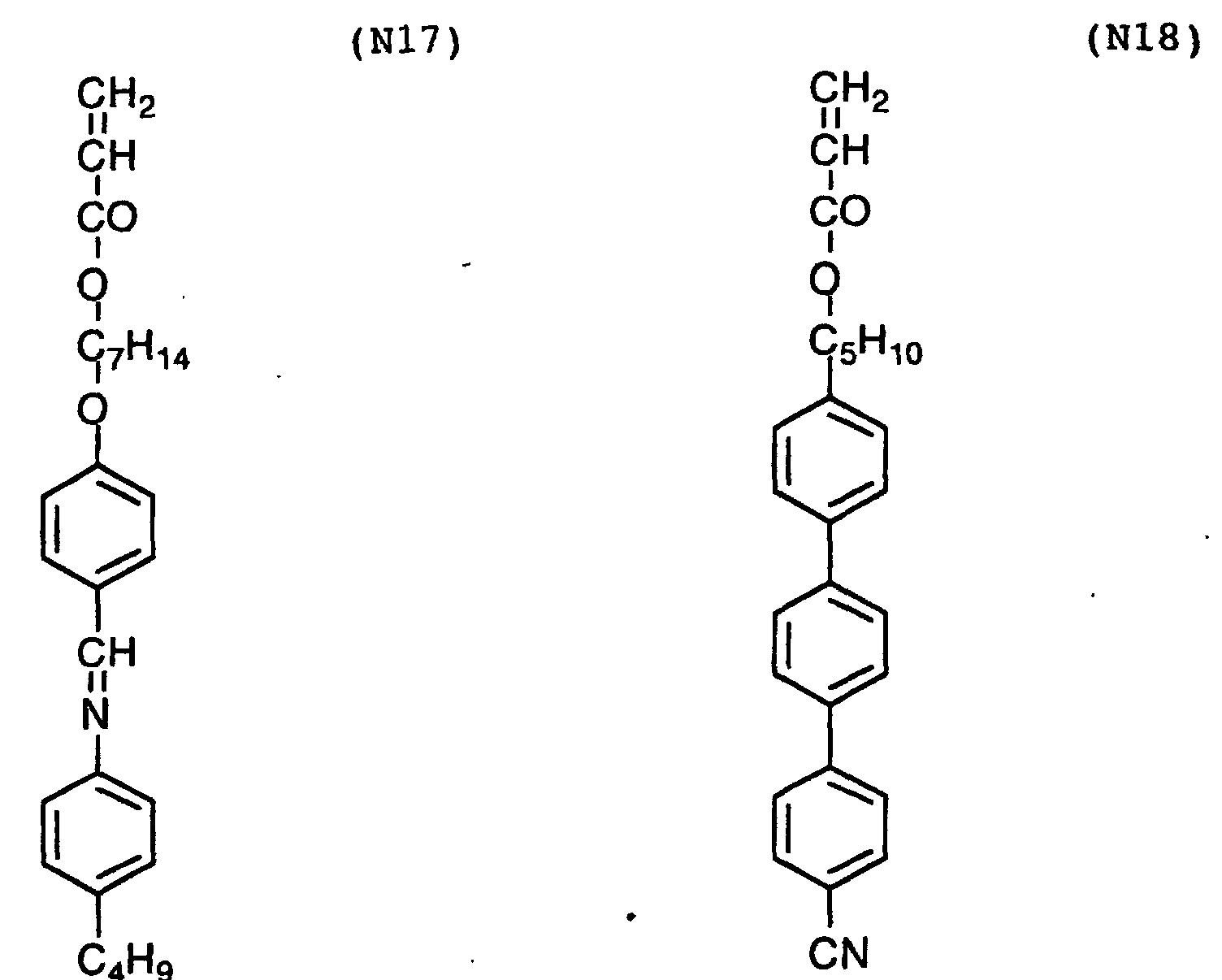
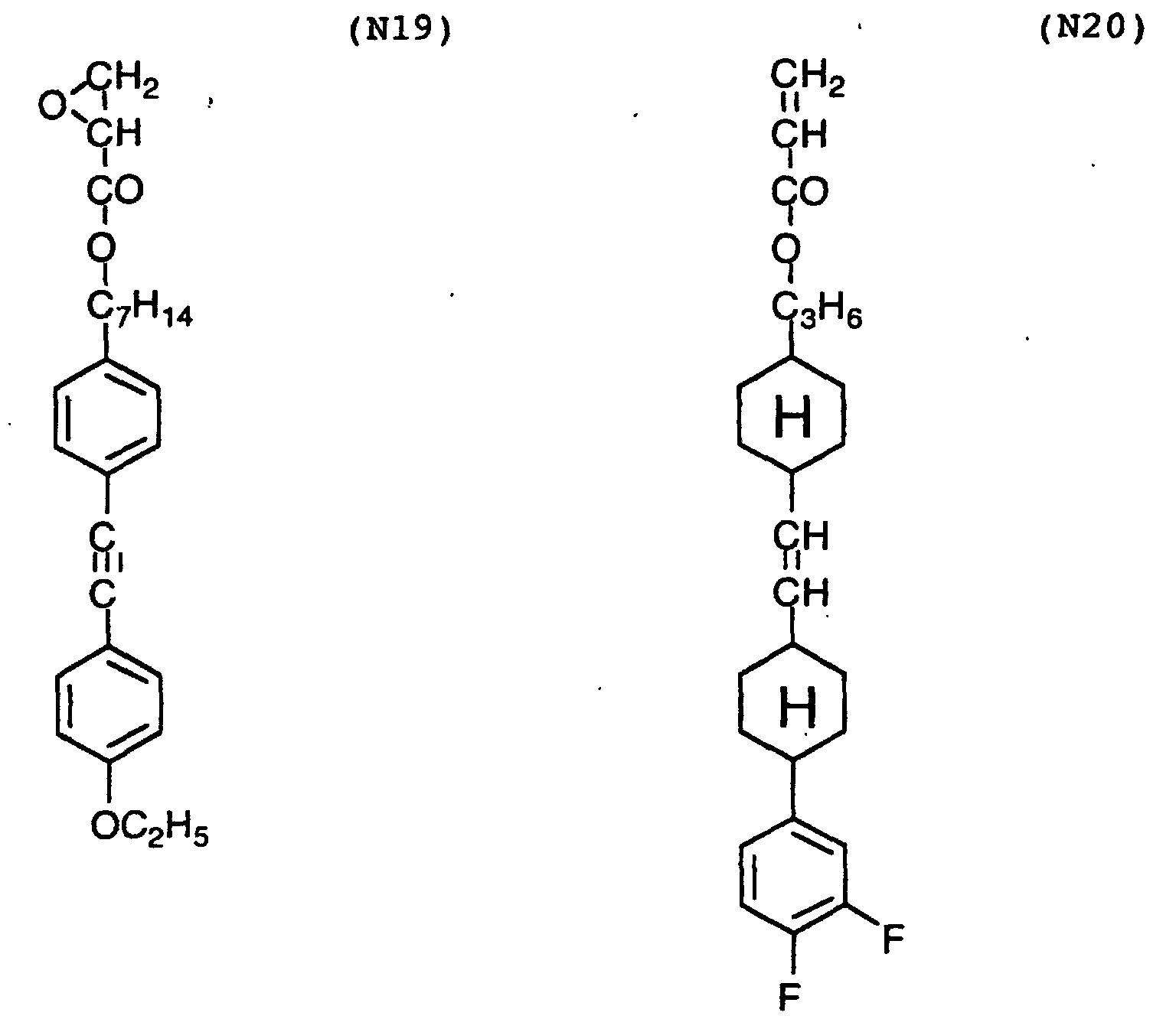
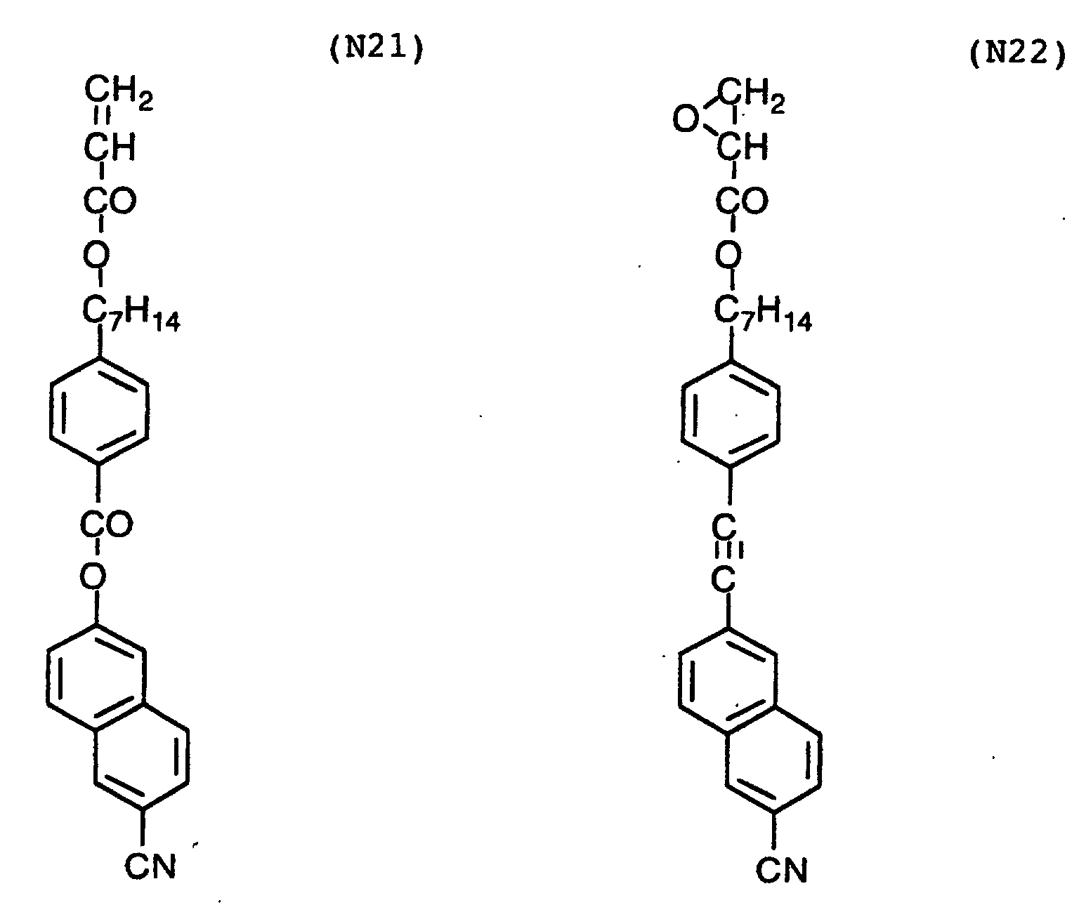
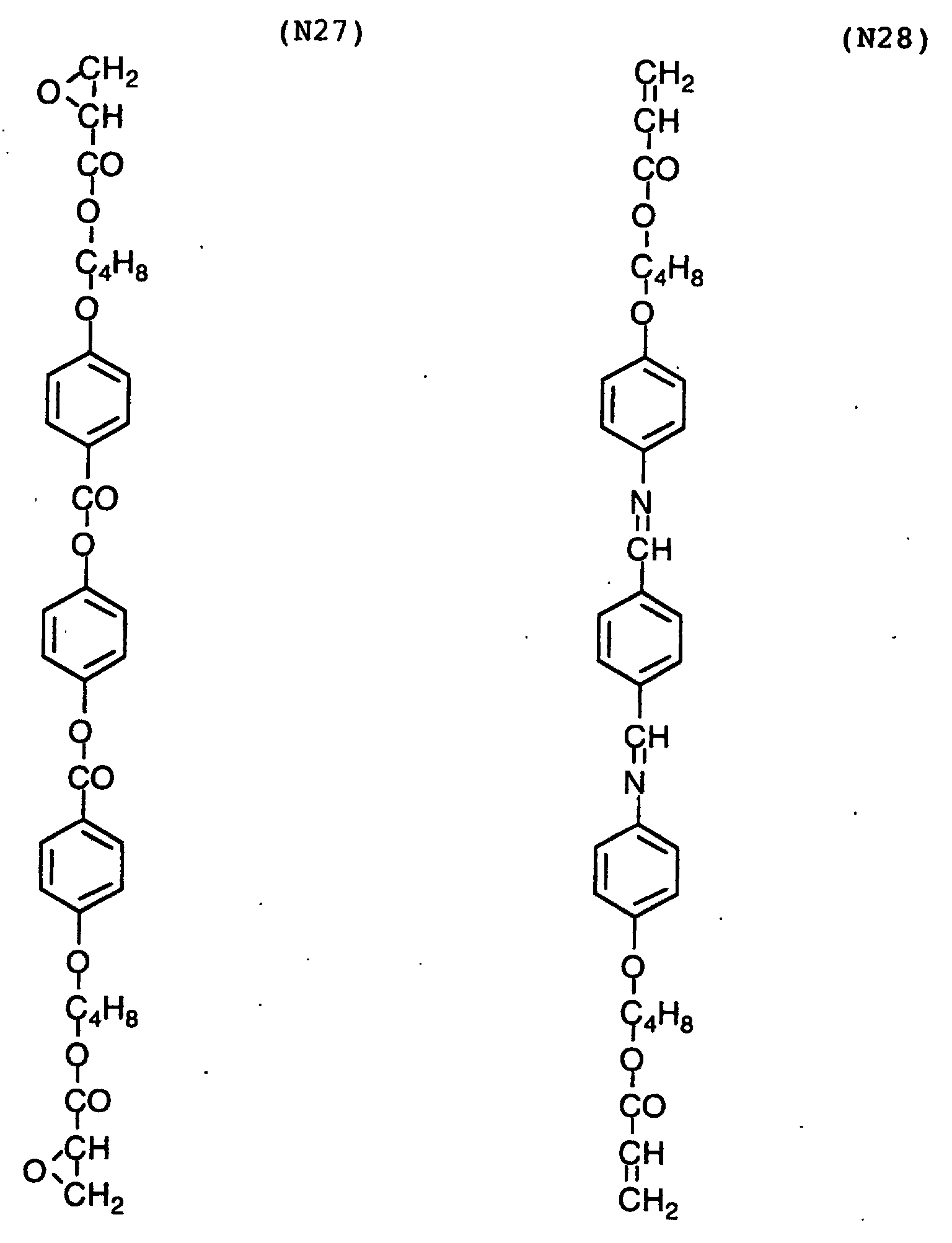
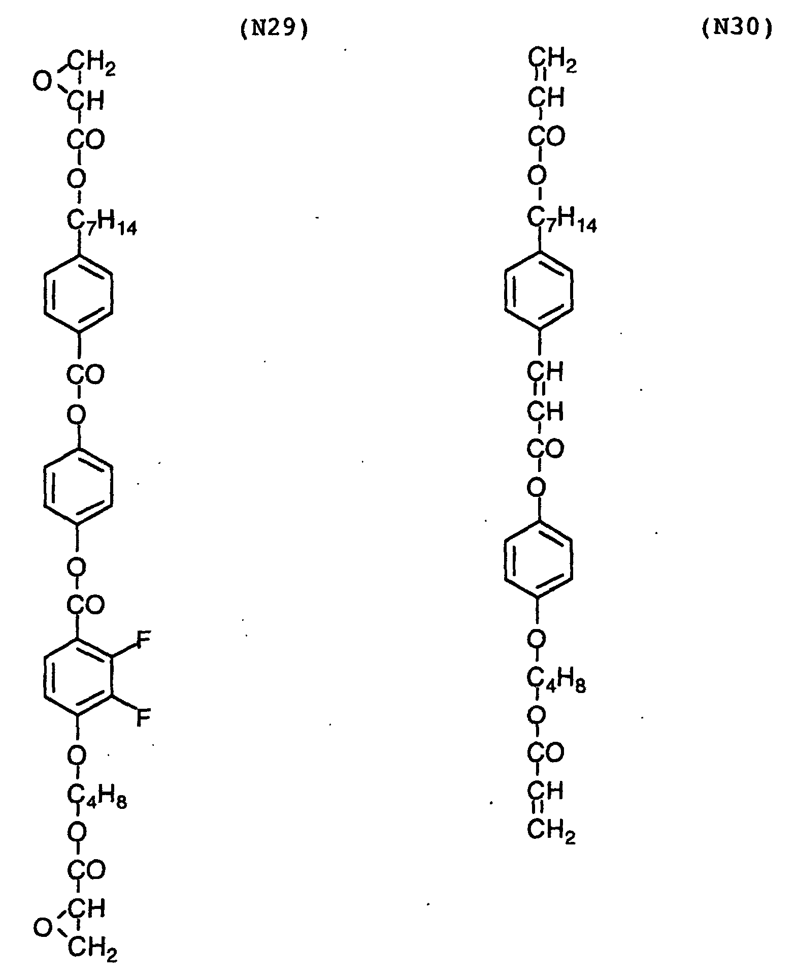
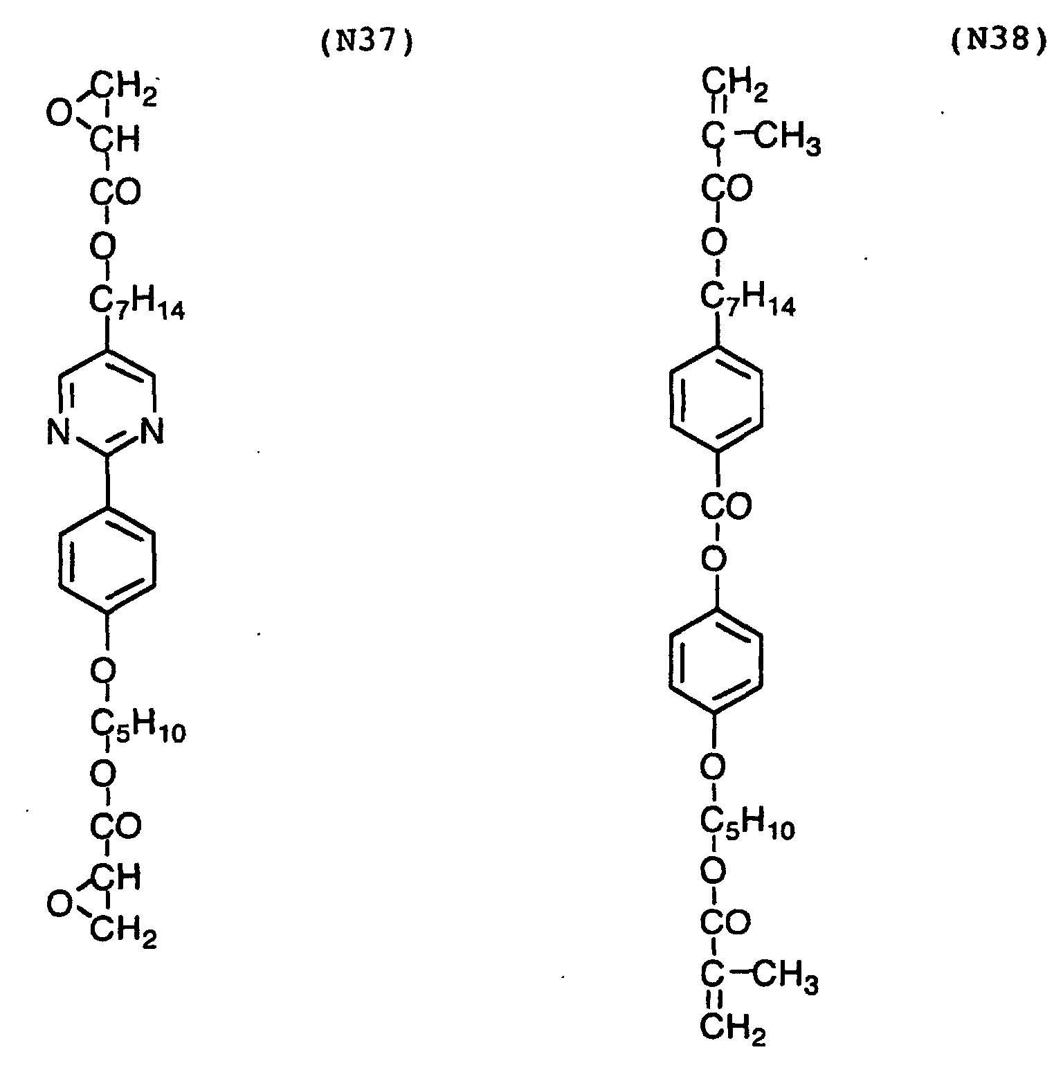
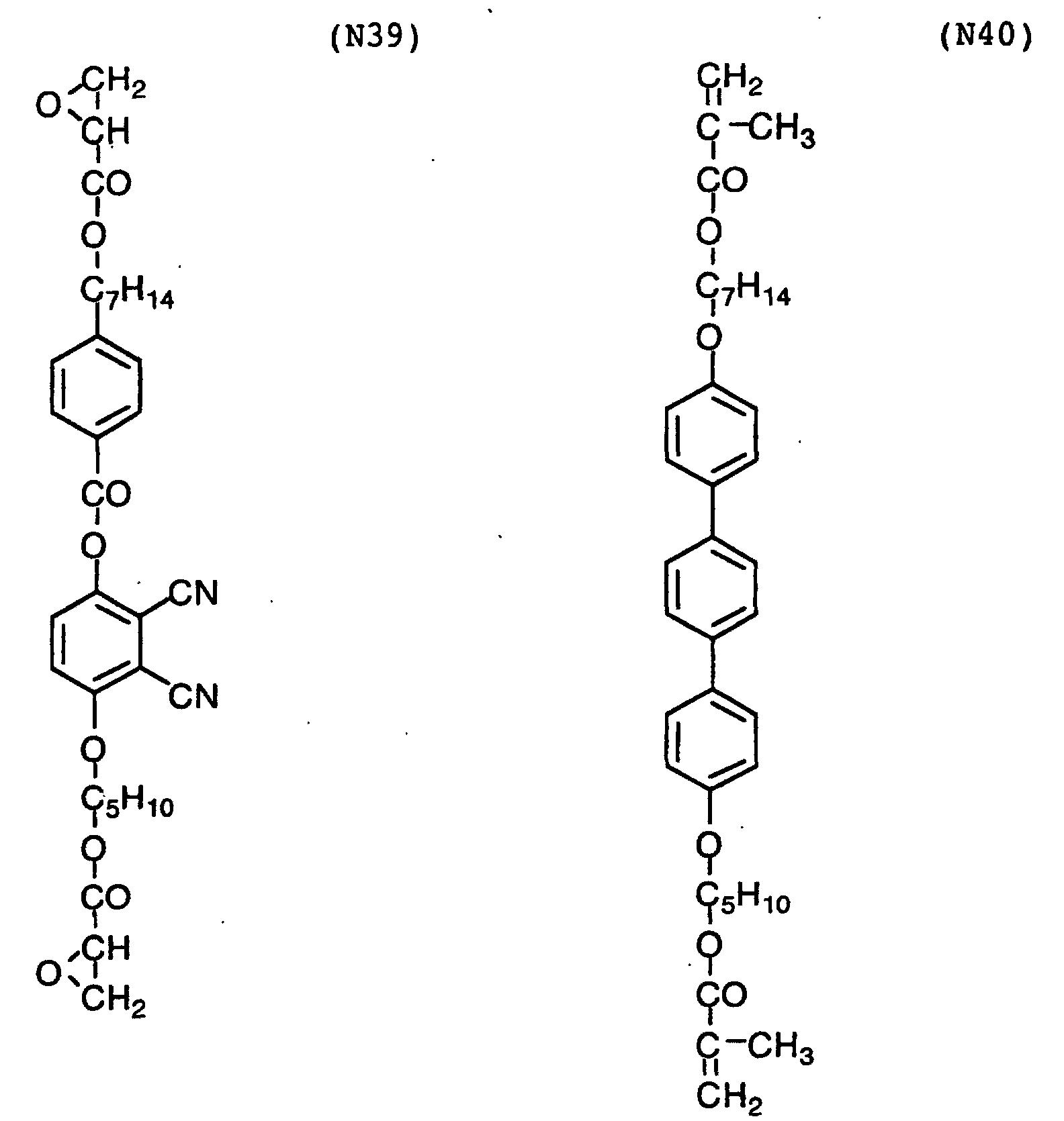
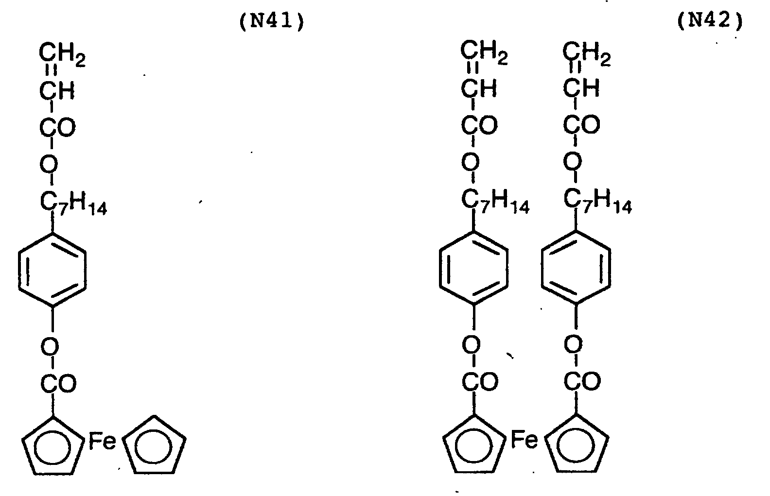
[Field of invention]
The present invention relates to a polarizing plate
comprises a light-scattering polarizing element, which selectively
transmits polarized light and selectively reflects
or scatters other polarized light, and a light-absorbing
polarizing element, which selectively transmits
polarized light and selectively absorbs other polarized
light.
The invention also relates to an image display element
having the polarizing plate, which improves efficiency of
light.
The invention further relates to an optical film,
which is advantageously used as a light-scattering polarizing
element.
[Background of invention]
Light emitted from natural light sources such as the
sun is generally non-polarized (randomly polarized). Light
emitted from artificial light sources such as a lamp is also
generally non-polarized. A polarizing plate can extract
polarized light (linearly, circularly or elliptically polarized
light) from non-polarized light. The extracted polarized
light can be used in various optical devices. For
example, a liquid crystal display widely used nowadays is
an instrument that utilizes characters of polarized light
to display an image.
The polarizing plates in a broad sense include linearly,
circularly and elliptically polarizing plates. However,
the term of the polarizing plate usually (in a narrow
sense) means only a linearly polarizing plate. In the present
specification, the polarizing plate means a linearly
polarizing plate, which is the basic polarizing plate.
A linearly polarizing plate generally used is a light-absorbing
polarizing element consisting of a polyvinyl alcohol
film. A polyvinyl alcohol film is stretched, and the
film adsorbs iodine or a dichromatic dye to prepare a polarizing
element. The stretched polarizing element has a
transmission axis (polarizing axis) perpendicular to the
stretching direction.
The light-absorbing polarizing element transmits only
a light component polarized parallel to the polarizing axis,
and absorbs a perpendicularly polarized component. Therefore,
usable light through the element is theoretically 50%
or less (practically, much less than 50%) of the original
light.
A light-scattering polarizing element has been proposed
in place of the light-absorbing polarizing element to
increase the amount of usable light (efficiency of light).
The light-scattering polarizing element also transmits only
the light component polarized parallel to the polarizing
axis, but scatters forward or backward the perpendicularly
polarized component. The light-scattering polarizing element
can improve the efficiency of light by using the scattered
light.
The light-scattering polarizing element is described
in Japanese Patent Provisional Publication Nos. 8(1996)-76114,
9(1997)-274108, 9(1997)-297204, Japanese Patent Publication
Nos. 11(1999)-502036, 11(1999)-509014, and U.S.
Patent Nos. 5,783,120, 5,825,543 and 5,867,316.
[Summary of the invention]
An object of the present invention is to provide a polarizing
plate improving efficiency of light.
Another object of the invention is to provide a liquid
crystal display giving clear images.
A further object of the invention is to provide an optical
film having scattering characters easily controllable,
even and large in a large area.
The present invention provides a polarizing plate comprises
a light-scattering polarizing element having a polarizing
layer which selectively transmits polarized light
and selectively reflects or scatters other polarized light,
and a light-absorbing polarizing element having a polarizing
layer which selectively transmits polarized light and
selectively absorbs polarized light, said elements being so
arranged that the polarizing transmission axis of the
light-scattering polarizing element is essentially parallel
to the polarizing transmission axis of the light-absorbing
polarizing element, and said polarizing layer in the light-scattering
polarizing element comprising an optically isotropic
continuous phase and an optically anisotropic discontinuous
phase.
The invention also provides a liquid crystal display
comprising a backlight, a polarizing plate, a liquid crystal
cell of twist nematic mode and another polarizing plate
in this order, wherein the polarizing plate on the backlight
comprises a light-scattering polarizing element having
a polarizing layer which selectively transmits polarized
light and selectively reflects or scatters other polarized
light, and a light-absorbing polarizing element
having a polarizing layer which selectively transmits polarized
light and selectively absorbs polarized light, said
elements being so arranged that the polarizing transmission
axis of the light-scattering polarizing element is essentially
parallel to the polarizing transmission axis of the
light-absorbing polarizing element, and said polarizing
layer in the light-scattering polarizing element comprising
an optically isotropic continuous phase and an optically
anisotropic discontinuous phase.
The invention further provides a liquid crystal display
comprising a backlight, a polarizing plate, a liquid
crystal cell of bend alignment mode and another polarizing
plate in this order, wherein the polarizing plate on the
backlight comprises a light-scattering polarizing element
having a polarizing layer which selectively transmits polarized
light and selectively reflects or scatters other
polarized light, and a light-absorbing polarizing element
having a polarizing layer which selectively transmits polarized
light and selectively absorbs polarized light, said
elements being so arranged that the polarizing transmission
axis of the light-scattering polarizing element is essentially
parallel to the polarizing transmission axis of the
light-absorbing polarizing element, and said polarizing
layer in the light-scattering polarizing element comprising
an optically isotropic continuous phase and an optically
anisotropic discontinuous phase.
The invention furthermore provides a liquid crystal
display comprising a backlight, a polarizing plate, a liquid
crystal cell of horizontal aligning mode and another
polarizing plate in this order, wherein the polarizing
plate on the backlight comprises a light-scattering polarizing
element having a polarizing layer which selectively
transmits polarized light and selectively reflects or scatters
other polarized light, and a light-absorbing polarizing
element having a polarizing layer which selectively
transmits polarized light and selectively absorbs polarized
light, said elements being so arranged that the polarizing
transmission axis of the light-scattering polarizing element
is essentially parallel to the polarizing transmission
axis of the light-absorbing polarizing element, and said
polarizing layer in the light-scattering polarizing element
comprising an optically isotropic continuous phase and an
optically anisotropic discontinuous phase.
The invention still furthermore provides an optical
film comprising a transparent support and a polarizing layer
which selectively transmits polarized light and selectively
reflects or scatters other polarized light, said polarizing
layer comprising an optically isotropic continuous
phase and an optically anisotropic discontinuous phase,
wherein the maximum transmittances for all rays is not less
than 75% and the minimum transmittances for all rays is
less than 60% where the transmittances are measured along
polarizing planes perpendicular to plane of the polarizing
layer.
In the present specification, the term "essentially
perpendicular", "essentially parallel" or "essentially at
the angle of 45°" means that the difference between the
theoretical angel (90°, 0° or 45°) and the measured angle
is less than ±5°. This difference is preferably less than
±4°, more preferably less than ±3°, and most preferably
less than ±2°.
The terms "slow axis" mean the direction giving the
maximum refractive index, and the term "transmission axis"
and the minimum refractive index, respectively.
[Brief description of the drawings]
Fig. 1 is a sectional view schematically illustrating
a basic structure of an optical film.
Fig. 2 is a sectional view schematically illustrating
a conventional liquid crystal display comprising only a
light-absorbing polarizing element.
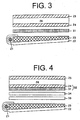
Fig. 3 is a sectional view schematically illustrating
a liquid crystal display comprising a light-absorbing polarizing
element and a light-scattering polarizing element,
wherein the elements are not laminated.
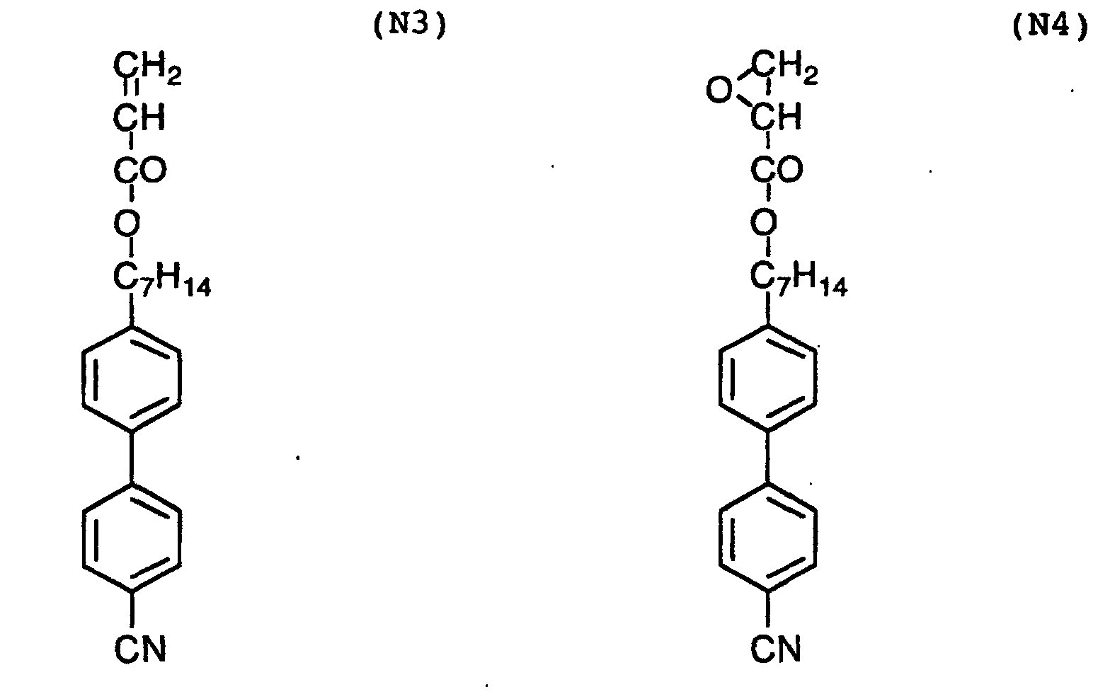
Fig. 4 is a sectional view schematically illustrating
a liquid crystal display having a polarizing plate comprising
a light-absorbing polarizing element and a light-scattering
polarizing element.
Fig. 5 is a sectional view schematically illustrating
another liquid crystal display having a polarizing plate
comprising a light-absorbing polarizing element and a
light-scattering polarizing element.
[Detailed description of the invention]
(Improvement of light efficiency by use of light-scattering
polarizing element)
The following mechanisms (A) to (C) using light-scattering
polarizing elements have been proposed to improve
efficiency of light. The mechanisms (A) to (C) can
be applied to the present invention.
(A) Depolarization of front scattered light
The light-scattering polarizing element scatters forward
or backward light polarized perpendicularly to the polarizing
axis. The light scattered forward (front scattered
light) is depolarized to rotate the polarizing direction.
The rotated direction is different from the polarizing
direction of the incident light. and hence the scattered
light has a light component polarized parallel to the
polarizing axis of the element. Consequently, the component
polarized in the polarizing direction of the element
is increased. If the polarizing element contains many particles
in the thickness direction, multiple scattering occurs
to enhance the depolarization. In this way, the efficiency
of light is improved by the depolarization of front
scattered light if the light-scattering polarizing element
is used, as compared with the efficiency when the light-absorbing
polarizing element is used alone.
(B) Reuse (depolarization) of back scattered light
The component scattered backward (back scattered
light) is depolarized when it is scattered. The back scattered
light is reflected by a metal reflector placed behind
the backlight (light source), and again enters the light-scattering
polarizing element. Since the depolarized light
(back scattered light) has the light component polarized
parallel to the polarizing axis of the element, a part of
the reentering light passes through the element. The scattering
on the polarizing element and the reflection on the
reflector are repeated in this way to improve the efficiency
of light.
(C) Reuse (rotation of polarizing direction) of back scattered
light
In an optical system comprising a λ/4 plate and a
metal reflector, incident light linearly polarized at 45°
to the slow axis of the λ/4 plate is reflected to rotate
its polarizing direction by 90°. For applying this effect,
a λ/4 plate is provided between the light-scattering polarizing
element and the metal reflector (placed behind the
backlight) so that the slow axis of the λ/4 plate may be
placed at 45° to the polarizing axis of the polarizing element.
The light scattered backward has a component polarized
perpendicularly to the polarizing axis of the polarizing
element in a large amount. Accordingly, the light scattered
backward, passed through the λ/4 plate, reflected by
the metal reflector and then reentering the polarizing element
has a light component polarized parallel to the polarizing
axis of the polarizing element in a large amount.
Since the light component parallel polarized can pass
through the polarizing element, the efficiency of light is
thus improved by the λ/4 plate provided between the light-scattering
polarizing element and the metal reflector.
(Structure of optical film and liquid crystal display)
Fig. 1 is a sectional view schematically illustrating
a basic structure of an optical film.
The optical film shown in Fig. 1 comprises a transparent
support (11) and a polarizing layer (12) provided
thereon. The polarizing layer (12) consists of an optically
isotropic continuous phase (13) and an optically anisotropic
discontinuous phase (14). The discontinuous phase
(14) comprises an optically anisotropic compound showing
birefringence, whose two birefringent indexes (n1, n2) in
the discontinuous phase depend on characters and aligning
degree of the optically anisotropic compound.
The optical film of Fig. 1 can serve as a light-scattering
polarizing element, where either n1 or n2 is essentially
the same as the refractive index of the continuous
phase (i.e., less than 0.05). The direction giving essentially
the same refractive index (n1 or n2) corresponds
to the transmission axis of the polarizing layer.
Fig. 2 is a sectional view schematically illustrating
a conventional liquid crystal display comprising only a
light-absorbing polarizing element.
The liquid crystal display shown in Fig. 2 comprises a
backlight (21) of edge light type as a light source placed
on the bottom. From the bottom side, a reflecting plate
(22) and a light-leading plate (23) are overlaid. These
plates make light of the backlight come out to the surface.
The backlight may be placed at the bottom (direct type),
and in that case the light-leading plate is unnecessary.
A liquid crystal cell (26) sandwiched between a pair
of polarizing elements of light-absorbing type (24, 25) is
placed above the light source (21) to display images. The
lower light-absorbing polarizing element (24) absorbs at
least 50% of light emitted from the light source (21).
Fig. 3 is a sectional view schematically illustrating
a liquid crystal display comprising a light-absorbing polarizing
element and a light-scattering polarizing element.
The liquid crystal display shown in Fig. 3 is that of
Fig. 2 supplemented with a light-scattering polarizing element
(31). The light-scattering polarizing element (31)
selectively transits the light component polarized parallel
to the transmission axis of the lower light-absorbing polarizing
element (24). At the same time, the light component
polarized perpendicularly to the transmission axis is
partially scattered forward by the element (31), and depolarized
to rotate the polarizing plane to be parallel to
the transmission axis. Consequently, the efficiency of
light is improved. On the other hand, the light component
polarized perpendicularly to the transmission axis is partially
scattered backward to the light source (21) side,
depolarized by the light-leading plate (23) and reflected
by the reflecting plate (22). The reflected light component
comes back to the element (31) to reuse, to further
improve the efficiency of light.
In the liquid crystal display of Fig. 3, the light-absorbing
polarizing element (24) and that of light-scattering
type (31) are not laminated. If they are laminated,
the efficiency of light is furthermore improved.
Fig. 4 is a sectional view schematically illustrating
a liquid crystal display equipped with a polarizing plate
comprising laminated polarizing elements of light-absorbing
type and light-scattering type.
In Fig. 4, light emitted from the light source (21) is
reflected by the reflecting plate (22), and passes through
the light-leading plate (23). The light is then made to
have even brightness in the plane by a scattering sheet
(33). The display of Fig. 4 comprises a film (34) condensing
light to a predetermined direction, and thereby light
extremely obliquely coming (users do not see such light) is
condensed to the front so as to improve the efficiency of
light. In this display, though the amount of light slightly
obliquely coming (users may see such light) is reduced,
the light is adequately defused by a polarizing plate (32)
comprising laminated polarizing elements of light-absorbing
type (24) and light-scattering type (31). Further, the polarizing
plate (32) comprising laminated polarizing elements
of light-absorbing type (24) and light-scattering
type (31) improves the brightness of the liquid crystal
display on the same principle as described above in Fig. 3.
Consequently, natural viewing angel distribution can be realized.
In the liquid crystal display of Fig. 3, the amount of
usable light is reduced by 10% because of reflection on the
surface of the light-scattering polarizing element (31) (in
the side opposite to the polarizing layer) and that on the
light-absorbing polarizing element (24). In contrast, in
the liquid crystal display of Fig. 4, those reflection surfaces
are omitted because the polarizing plate (32) comprising
laminated polarizing elements of light-absorbing
type (24) and light-scattering type (31) is use, and hence
the efficiency of light is improved at least by 10%.
Fig. 5 is a sectional view schematically illustrating
another liquid crystal display equipped with a polarizing
plate comprising laminated polarizing elements of light-absorbing
type and light-scattering type.
In the display of Fig. 5, the polarizing plate (32)
comprising laminated polarizing elements of light-absorbing
type (24) and light-scattering type (31) is further improved
in brightness. On the polarizing layer of the
light-scattering polarizing element (31), an anti-reflection
layer (35) is provided directly or via another
layer so as to reduce reflection on the surface and to increase
the amount of light coming into the polarizing layer.
Further, a λ/4 plate (36) is provided below the polarizing
plate (32). Because of rotation of polarizing direction of
light scattered backward (back scattered light) described
above in (C), back scattered light polarized perpendicularly
to the transmission axis of the light-absorbing polarizing
element (31) passes through the λ/4 plate (36)
twice so that the polarizing axis may rotate to be parallel
to the transmission axis of the element of light-absorbing
type (31), so as to remarkably improve the efficiency of
light. The other components such as the light source (21),
the reflecting plate (22), the light-leading plate (23),
the scattering sheet (33) and the light-condensing film
(34) can function in the same manner as in the liquid crystal
display of Fig. 4.
(Transparent support)
The polarizing plate preferably has at least one
transparent support. The polarizing elements of light-absorbing
type and light-scattering type may share one
transparent support, or otherwise each element may have a
transparent support. Further, two transparent supports may
be provided to protect both surfaces of the polarizing layer
in the light-absorbing polarizing element or light-scattering
type.
The term "transparent" in the transparent support
means that the support has a light transmittance of 80% or
more. Further, the support preferably shows optical isotropy
when seen from the front. It is, therefore, preferred
that the support be made of materials showing small birefringence.
However, the optically isotropic transparent
support can be made of materials even showing large birefringence
(e.g., polycarbonate, polyester, polyarylate,
polysulfone, polyethersulfone) if conditions of film forming
(solvent cast, melt extruding) or of stretching laterally
or longitudinally are adequately selected.
As the transparent support, a glass plate or a polymer
film can be used. Examples of material for the polymer
film include polyolefin (e.g., polyethylene), norbornene
resin, polyethylene terephthalate, polyethylene naphthalate,
polypropylene, polycarbonate, polystyrene (e.g., syndiotactic
polystyrene), polyarylate, polysulfone, polyethersulfone,
polyvinyl chloride, polyvinyl alcohol and cellulose
ester (e.g., cellulose acetate). The film may be made of a
mixture of two or more polymers. Commercially available
polymers (e.g., Zeonex, Zeonoa [Nippon Zeon Co., Ltd.];
ARTON [JSR Co., Ltd.]; Fujitac [Fiji Photo film Co., Ltd.];
triacetyl cellulose) are also usable.
The transparent support preferably protects the polarizing
layer (particularly, the polarizing layer of the
light-absorbing polarizing element). In consideration of
protecting, a film of cellulose acetate is preferred. The
acetic acid content of cellulose acetate is preferably in
the range of 55 to 61.5% (cellulose diacetate or cellulose
triacetate), more preferably in the range of 59 to 61%
(cellulose triacetate).
In the case where a cellulose triacetate film is used
as the transparent support, the film is preferably produced
essentially without the solvent of halogenated hydrocarbon.
When a conventional cellulose triacetate film is produced,
a halogenated hydrocarbon (particularly, methylene chloride)
is generally used as a solvent. However, in consideration
of environmental problems, use of halogenated hydrocarbon
has been gradually restricted. On the other hand,
it has been difficult for organic solvents other than halogenated
hydrocarbon to dissolve cellulose triacetate. Japanese
Patent Provisional publication Nos. 9(1997)-95538,
9(1997)-95544 and 9(1997)-95557 disclose a method in which
cellulose triacetate is cooled to dissolve in a normal organic
solvent (ester, ether, ketone or alcohol having 3 to
12 carbon atoms). This method makes it possible to produce
a cellulose triacetate film essentially without the solvent
of halogenated hydrocarbon. The term "essentially without
the solvent of halogenated hydrocarbon" mean that the solvent
used in producing the film contains halogenated hydrocarbon
in an amount of 5 wt.% or less (preferably, 1 wt.%
or less). It is preferred that no halogenated hydrocarbon
be found in the resultant cellulose triacetate film.
The thickness of the transparent support is preferably
in the range of 10 to 500 µm, more preferably in the range
of 40 to 200 µm.
The support may be subjected to a surface treatment
(e.g., chemical treatment, mechanical treatment, corona
discharge treatment, glow discharge treatment). Saponification
treatment is a typical chemical treatment.
An undercoating layer may be provided on the support
to enhance adhesion between the support and a neighboring
layer such as the polarizing layer. If the transparent
support is a cellulose triacetate film, the undercoating
layer can be made of gelatin, poly(meth)acrylate,
poly(meth)acrylamide, polystyrene, polybutadiene or a copolymer
thereof.
(Optically isotropic continuous phase)
The light-scattering polarizing element comprises a
polarizing layer which selectively transmits particular polarized
light and which selectively reflects or scatters
other polarized light. The "particular polarized light"
and the "other polarized light" generally have polarizing
planes crossing perpendicularly to each other. The polarizing
layer in the light-scattering polarizing element consists
of an optically isotropic continuous phase and an optically
anisotropic discontinuous phase.
The amount of the optically isotropic continuous phase
is preferably in the range of 5 to 95 wt.%, more preferably
in the range of 20 to 90 wt.%, most preferably in the range
of 50 to 80 wt.% based on the weight of the polarizing
layer.
The term "optically isotropic" means having an optical
anisotropy of less than 0.05. (With respect to the optical
anisotropy, the definition is below given in the description
of optically anisotropic discontinuous phase.)
The optically isotropic continuous phase may be in the
form of polymer matrix. The polymer constituting the continuous
phase may have been a polymer in preparing the polarizing
layer (for example, in a coating solution for preparing
the layer), or otherwise may have been monomers at
that stage, followed by polymerizing the monomers.
As the polymer, a polymer having high optical isotropy
is used. However, even a polymer giving relatively high
birefringence (e.g., polycarbonate, polystyrene) can be
used if additives are incorporated to make the polymer optically
isotropic.
The efficiency of backlight is more improved where the
incident light coming into the light-scattering polarizing
element is less reflected. Hence, the polymer matrix constituting
the continuous phase has an average refractive
index (n) of preferably not more than 1.70, more preferably
not more than 1.6, most preferably not more than 1.55. The
average refractive index (n) is represented by the formula:
n = (nx+ny+nz)/3.
In the formula, nx is a refractive index along the
slow axis in plane; ny is a refractive index along the axis
of light progression in plane; and nz is a refractive index
in the thickness direction.
Examples of the polymer used for the optically isotropic
continuous phase include proteins (e.g., gelatin, casein),
polysaccharides (e.g., agarose, cellulose, pullulan,
carrageenan, polygalacturonic acid, alginic acid), cellulose
ethers, cellulose esters (e.g., cellulose acetate,
cellulose diacetate, cellulose triacetate, cellulose propionate,
cellulose butylate, cellulose acetatepropionate,
cellulose nitrate), polyolefins (e.g., polyethylene, polypropylene,
polymethyl pentene), polyolefin derivatives
(e.g., polyvinyl chloride, polyvinyl alcohol, denatured
polyvinyl alcohol, norbornene resin), polystyrene (e.g.,
syndiotactic polystyrene), polyesters (e.g., polyethylene
terephthalate, polyethylene naphthalate, polycarbonate,
poly-1,4-cyclohexanedimethyleneterephthalate, polyethylene-1,2-diphenoxyethane-4,4'-dicarboxylate,
polybutylene terephthalate),
polyamide, polysulfone, polyethersulfone, polyarylate,
polyether imide, polyether ketone, polyacrylic
esters and polymethacrylic esters (e.g., methyl methacrylate).
A mixture of two or more polymers can be used. Commercially
available polymers (e.g., Zeonex, Zeonoa [Nippon
zeon Co., Ltd.]; ARTON [JSR Co., Ltd.]; Fujitac [Fiji Photo
film Co., Ltd.]; triacetyl cellulose) are also usable.
A monomer forming the polymer for the optically isotropic
continuous phase is preferably polymerized by heat or
ionization radiation. Examples of polymerizable groups of
the monomers include an ethylenically unsaturated polymerizable
group, isocyanate group, epoxy group, aziridine
group, oxazolidine group, aldehyde group, carbonyl group,
hydrazine group, carboxyl group, methylol group, active
methylene group, vinylsulfonic acid, acid anhydride bonding
(-CO-O-CO-), cyanoacrylate group, melamine, etherized methylol,
ester bonding, urethane bonding, and methal alkoxide
(tetramethoxysilane) structure. An ethylenically unsaturated
polymerizable group is preferred. It is particularly
preferred that a monomer having two or more ethylenically
unsaturated polymerizable groups be polymerized to form a
polymer having crosslinked structure.
Examples of the monomer having two or more ethylenically
unsaturated polymerizable groups include esters of
polyhydric alcohol and (meth)acrylic acid (e.g., ethylene
glycol di(meth)acrylate, 1,4-dichlorohexane acrylate, pentaerythritol
tetra(meth)acrylate, pentaerythritol
tri(meth)acrylate, trimethylolpropane tri(meth)acrylate,
trimethylolethane tri(meth)acrylate, dipentaerythritol
tetra(meth)acrylate, dipentaerythritol penta(meth)acrylate,
pentaerythritol hexa(meth)acrylate, 1,3,5-cyclohexanetriol
triacrylate, polyurethane polyacrylate, polyester polyacrylate),
vinylbenzene and derivatives thereof (e.g., 1,4-divinylbenzene,
4-vinylbenzoic acid-2-acryloyl ethylester,
1,4-divinylcyclohexanone), vinylsulfones (e.g., divinylsulfone),
acrylamides (e.g., methylene bisacrylamide) and
methacrylamide.
In the case where the discontinuous phase is made to
be optically anisotropic by stretching (aligning the liquid
crystal compound), the optically isotropic continuous phase
preferably contains a compound (plasticizer) to lower the
glass transition temperature of the polymer of the continuous
phase. Examples of the plasticizer include carboxylic
esters (e.g., dibutyl phthalate), phosphoric esters (e.g.,
triphenyl phosphate) and polyhydric alcohols (e.g., glycerol).
If an water-soluble polymer is used in the continuous
phase, glycerol is particularly preferably incorporated.
(Optically anisotropic discontinuous phase)
The amount of the optically anisotropic discontinuous
phase is preferably not less than 3 wt.%, more preferably
not less than 4 wt.%, further preferably not less than 5
wt.%, furthermore preferably not less than 10 wt.%, most
preferably not less than 20 wt.% based on the weight of the
polarizing layer. Also, the amount of the optically anisotropic
discontinuous phase is preferably not more than 95
wt.%, more preferably not more than 80 wt.%, further preferably
not more than 60 wt.%, furthermore preferably not
more than 50 wt.%, most preferably not more than 40 wt.%
based on the weight of the polarizing layer.
The term "optically anisotropic" means having an optical
anisotropy of not less than 0.05. The optical anisotropy
corresponds to birefringence |n1-n2|, which is the absolute
value of difference between the refractive index
(n1) along an axis included in the polarizing plane giving
the maximum transmittance for all rays coming to the polarizing
layer and the refractive index (n2) along an axis included
in the polarizing plane giving the minimum transmittance
for all rays. The optical anisotropy is preferably
in the range of 0.05 to 1.00, more preferably in the range
of 0.10 to 1.00, most preferably in the range of 0.15 to
1.00.
In order that the optical film can work as the light-scattering
polarizing element, one of the refractive indexes
(n1, n2) of the optically anisotropic discontinuous
phase must be essentially the same as the refractive index
of the optically isotropic continuous phase. The term "essentially
the same" means that the difference between them
is less than 0.05. The difference is preferably less than
0.01, more preferably less than 0.001. The direction in
which the refractive index of the discontinuous phase and
that of the continuous phase are the same corresponds to
the transmission axis of the polarizing layer.
The optically anisotropic discontinuous phase is in
the form of particles or drops dispersed in the optically
isotropic continuous phase. The mean size of the particles
or drops (mean radius of approximated circles having the
same areas as the projected areas of the particles or
drops) is preferably in the range of 0.01 to 10 µm, more
preferably in the range of 0.05 to 5 µm, most preferably in
the range of 0.05 to 1 µm.
There is no particular restriction on the shapes of
the particles or drops. They may have spherical shape
(having an average aspect ratio of not more than 2) or irregular
shape (having a large surface area).
The optically anisotropic discontinuous phase is made
of optically anisotropic material. After the polarizing
layer is formed, the material is preferably exposed to
light or stretched in a certain direction so that the material
may have optical anisotropy (may be aligned).
As the optically anisotropic material, a photo-orienting
compound (photo-reactive compound or photo-isomerizing
compound), a liquid crystal compound or a mixture
thereof is preferably used. The photo-orienting compound
and the mixture of photo-orienting compound and liquid
crystal compound can be made optically anisotropic by
irradiation of light in a certain direction. If the liquid
crystal compound itself naturally aligns along the direction
in which light comes (namely, if the liquid crystal
compound has a photo-reactive or photo-isomerizing group
described after), even the liquid crystal compound alone
can be made optical anisotropic by irradiation of light in
a certain direction.
The photo-orienting compound (photo-reactive compound
or photo-isomerizing compound) is preferably a polymer,
namely a photo-reactive or photo-isomerizing polymer. The
photo-reactive polymer is further categorized into a photo-dimerizing
polymer and a photo-decomposing polymer.
The photo-dimerizing polymer has a photosensitive
group of photo-dimerization type at the side chain. Two
photosensitive groups of photo-dimerization type react to
form a ring through additional reaction when exposed to
light (preferably, ultraviolet light), and thereby the polymers
are dimerized through the additional reaction. The
photo-dimerization reaction is described in "Photosensitive
polymer" (Kan Nagamatsu, Kodansha 1977).
The photosensitive group of photo-dimerization type
preferably comprises (a) carbonyl group or (b) ethylenically
unsaturated bond, and (c) aromatic group or (d) heterocyclic
group. The group more preferably has both of (a)
carbonyl group and (b) ethylenically unsaturated bond, and
(c) aromatic group is preferred to (d) heterocyclic group.
Namely, the photosensitive group of photo-dimerization type
preferably comprises (a) carbonyl group, (b) ethylenically
unsaturated bond and (c) aromatic group.
The carbonyl group (a) is preferably contained in an
acyl group, an acyloxy group or an alkoxycarbonyl group.
The ethylenically unsaturated bond (b) is preferably
in cis form to in trans form. If plural ethylenically unsaturated
bonds are contained, they are preferably conjugated.
In the functional group having (a) carbonyl group, (b)
ethylenically unsaturated bond and (c) aromatic group,
those groups are preferably linked in the form of (main
chain)-(a)-(b)-(c). Examples of the functional group having
(a), (b) and (c) include cinnamoyl and phenylmaleimide.
The compound having cinnamoyl is described in
Jpn.J.Appl.Phys., 31. pp. 2155 (1992).
In the photo-dimerizing polymer, the main chain and
the side chain are linked through an ester bond preferably
containing (a) carbonyl group.
The ethylenically unsaturated bond (b), the aromatic
group (c) and the heterocyclic group (d) may have substituent
groups. Examples of the substituent group include an
alkyl group (e.g., methyl, ethyl, propyl, butyl, hexyl), an
alkoxy group (e.g., methoxy, ethoxy, propoxy, butoxy), an
alkenyl group (e.g., allyl), an alkenyloxy group (e.g., allyloxy),
aryl groups (e.g., phenyl), an aryloxy group (e.g.,
phenoxy), cyano, an alkoxycarbonyl group (e.g., methoxycarbonyl,
ethoxycarbonyl), hydroxyl, an alkyl-substituted amino
group (e.g., dimethylamino, diethylamino) and nitro.
Preferred groups are an alkyl group having 1 to 6 carbon
atoms, an alkoxy group having 1 to 6 cabon atoms, cyano and
an alkoxycarbonyl group having 1 to 6 carbon atoms.
The photo-dimerizing polymer having a photosensitive
group of photo-dimerization type at the side chain can be
synthesized in various manners.
For example, compounds (monomers) having a photosensitive
group and a polymerizable group are polymerized into
the polymer. As the polymerizable group, acryloyl group or
methacryloyl group is preferred. The polymer can be easily
synthesized by radical polymerization of (meth)acryloyl
group. Further, the polymer may be polyester, polyamide,
polyimide or polyurethane, which can be synthesized by condensation
polymerization of polymerizable group such as hydroxyl,
carboxyl, amino or cyanate. In that case, the
monomers must have at least two polymerizable groups.
The compound having a photosensitive group may be reacted
with a polymer to synthesize the polymer having photosensitive
groups. As the polymer reacted with the compound
having a photosensitive group, polyvinyl alcohol or
poly(meth)acrylic acid is preferred. The linkage between
polymer (main chain) and the compound (side chain) is preferably
ether bond, ester bond or amide bond.
A typical example of the photo-dimerizing polymer is
polyvinyl cinnamate.
Instead of using the photo-dimerizing polymer, a compound
having a photosensitive group may be dispersed in a
polymer (binder). As the polymer of binder, a
(meth)acrylic polymer, polyester or polyurethane is preferred.
After the compound having a photosensitive group
is dispersed in the binder, a polymerization initiator may
be added to polymerize.
Examples of the photo-decomposing polymer include
polyimide. The photo-decomposing polyimide is described in
Japanese Patent Provisional Publication Nos. 5(1993)-34699,
6(1994)-289399, 8(1996)-122792; and "Abstract of 22nd Forum
on liquid crystal", pp. 1672 A17 (1996). The photo-dimerizing
polymer is preferred to the photo-decomposing
one.
The photo-isomerizing compound is generally known as a
photochromic compound. When exposed to light, the photo-isomerizing
compound changes the chemical structure, and
accordingly changes properties (for example, color). Generally,
these changes are reversible.
Examples of the photo-isomerizing compound include
azobenzene compounds [described in K. Ichimura et al.,
Langmuir, vol. 4, page 1214 (1988); K. Aoki et al,. Langmuir,
vol. 8, page 1007 (1992); Y. Suzuki et al., Langmuir,
vol. 8, page 2601 (1992); K. Ichimura et al., Appl. Phys.
Lett., vol. 63, No. 4, page 449 (1993); N. Ishizuki, et al.,
Langmuir, vol. 9, page 3298 (1993); N. Ishizuki, Langmuir,
vol. 9, page 857 (1993)], chalcone compounds [described in
Nature, 381, pp. 212 (1998)], coumarin compounds [SID '98.
Digest, pp. 734 (1998)], hydrozano-β-ketoester compounds [S.
Yamamura et al., Liquid Crystals, vol. 13, No. 2, page 189
(1993)], stilbene compounds [K. Ichimura et al., "Papers on
polymers", vol. 47, No. 10, page 771 (1990), (Japanese)]
and spiropyrone compounds (K. Ichimura et al., Chemistry
Letters, page 1063 (1992); K. Ichimura et al., Thin Solid
Films, vol. 235, page 101 (1993)].
The photo-isomerizing compound preferably has the double
bond of C=C, C=N or N=N. The photochromic compound
having the double bond comprises the following indispensable
structural elements (1) and (2) and the following
optional structural elements (3) to (5):
The double bond structure (1) is preferably in trans
form to in cis form. Two or more double bonds may be contained,
and if so they are preferably conjugated.
Examples of the cyclic structure (2) include benzene
ring, naphthalene ring and nitrogen-containing heterocyclic
ring (e.g., pyridinium ring, benzo pyridinium ring). In
the case where the cyclic structure is a nitrogen-containing
heterocyclic ring, the carbon atom (not nitrogen
atom) in the ring preferably connects to the carbon or nitrogen
atom in the double bond (1). The cyclic structure
is preferably benzene ring.
Examples of the linking group (3) include -NH- and
-CO-. It is, however, preferred for the double bond structure
(1) to connect directly to the cyclic structure (2)
without the linking group (3).
Examples of the substituent group (4) include an aryl
group (e.g., phenyl) and cyano. However, the carbon atom
in the double bond structure (1) preferably has no substituent
group except the structure (2). This means that
the structure (1) is preferably -CH=CH- or -CH=N-.
Examples of the substituent group (5) include an
alkoxy group (e.g., methoxy, hexyloxy), cyano, an alkyl
group (e.g., butyl, hexyl) and an alkylamino group (e.g.,
dimethylamino). If the cyclic structure (2) is benzene,
the substituent group is positioned preferably at para- position.
As described after, in the case where a photochromic
compound is chemically combined with the polymer, a
functional group for connecting to the polymer is introduced
as the substituent group (5) into the photo-isomerizing
compound.
When the photo-isomerizing compound is used, it is
preferably combined chemically with the polymer. The polymer
is preferably hydrophilic (e.g., gelatin, polyvinyl
alcohol). Polyvinyl alcohol is particularly preferred.
The reaction between the photo-isomerizing compound
and the polymer is determined according to the kind of the
polymer (particularly, the kind of the functional group).
For example, if the polymer is a hydroxyl-containing polymer
such as polyvinyl alcohol, the reaction between acid
halide and hydroxyl can be adopted to combine the photo-isomerizing
compound with the polymer. In detail, a halogenated
acyl group (-COX in which X is halogen) is introduced
as a substituent group into the photo-isomerizing
compound, and the chemical linkage is formed through the
reaction between the halogenated acyl group and hydroxyl in
the polymer:
Ph-COX + HO-P1 → Ph-CO-O-P1 + HX
in which Ph is the photo-isomerizing compound, and P1 is
the main chain of the polymer.
The photo-orienting compound (photo-reactive compound
or photo-isomerizing compound) preferably contains, as the
photo-orienting functional group, azobenzene structure,
stilbene structure, cinnamoyl structure, chalcone structure,
coumarin structure or polyimide structure. Preferred
photo-orienting functional groups are azobenzene structure,
stilbene structure, cinnamoyl structure, chalcone structure
and coumarin structure. Particularly preferred functional
groups are cinnamoyl structure, chalcone structure and coumarin
structure.
In the case where the photo-orienting compound and the
liquid crystal compound are used in combination, the optically
anisotropic discontinuous phase contains the photo-orienting
compound preferably in an amount of 0.05 to 10
wt.%, more preferably in an amount of 0.1 to 5 wt.%.
Examples of the photo-orienting compound are shown below
in the form of repeating unit in the polymer. The polymer
may be a copolymer having other repeating units.
The liquid crystal compound preferably comprises three
or more π conjugations. For showing satisfying optical
anisotropy, the liquid crystal compound preferably has very
different refractive indexes for ordinary ray and extraordinary
ray. Further, the liquid crystal compound preferably
forms nematic phase or smectic phase. Rod-like liquid
crystal compounds are particularly preferred.
Examples of the rod-like liquid crystal compounds include
azomethines, azoxys, cyanobiphenyls, cyanophenyl esters,
benzoic esters, phenyl esters of cyclohexanecarboxylates,
cyanophenylcyclohexanes, cyano-substituted phenylpyrimidines,
alkoxy-substituted phenylpyrimidines, phen-yldioxanes,
tolanes and alkenylcyclohexylbenzonitriles.
Metal complexes are also included in the rod-like liquid
crystal compounds.
Descriptions of the rod-like liquid crystal compounds
are found in "Kagaku-Sosetsu, Ekisho no Kageku" (written in
Japanese), vol. 22(1994), Chapters 4, 7 and 11; and "Ekisho
Devise Handbook" (written in Japanese), chapter 3.
The rod-like liquid crystal compound has a characteristic
birefringent index of preferably 0.001 or more, more
preferably 0.05 or more, most preferably 0.10 or more. The
characteristic birefringent index is also preferably 1.00
or less, more preferably 0.70 or less.
The rod-like liquid crystal compound preferably comprises
a polymerizable group. As the polymerizable group,
an unsaturated polymerizable group, an epoxy group and an
aziridinyl group are preferred. An unsaturated polymerizable
group is more preferred, and an ethylenically unsaturated
group is most preferred.
The rod-like liquid crystal compound preferably has a
symmetric structure with respect to the short axis, and
hence it preferably has the polymerizable groups at each
end.
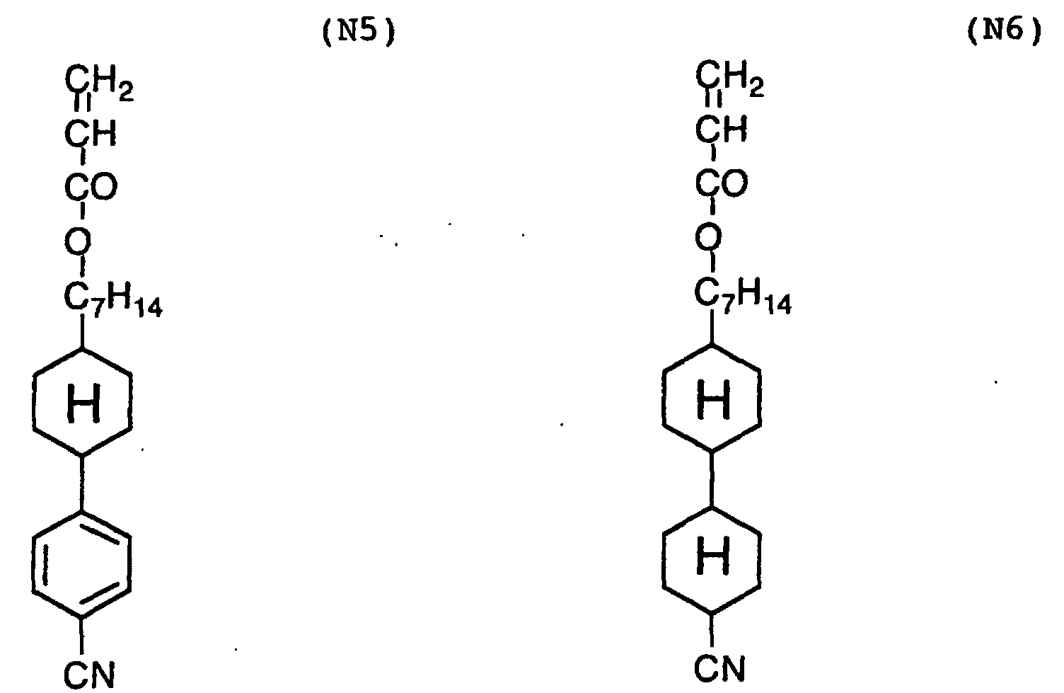
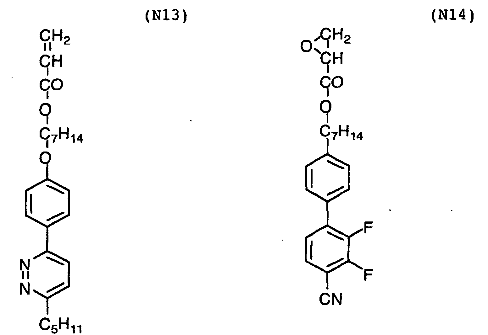
Examples of the rod-like liquid crystal compound are
shown below.
Two or more kinds of the photo-reactive compounds, the
photo-isomerizing compounds or the liquid crystal compounds
may be used in combination. Besides the photo-reactive
compound, the photo-isomerizing compound or the liquid
crystal compound, the optically anisotropic discontinuous
phase may further contain a plasticizer, a binder polymer
or a photo-polymerization initiator, if needed. The plasticizer
is preferably polymerizable.
(Formation of polarizing layer of light-scattering polarizing
element)
The polarizing layer of the light-scattering polarizing
element can be formed through the following steps (I)
to (III):
In the step (I), a stirring machine (e.g., homogenizer)
or a mixer (e.g., sand mill, colloid mill) is preferably
used to emulsify or disperse the materials.
For making the particle sizes of the optically anisotropic
discontinuous phase fine and even, a surface active
agent may be added. The surface active agent also improves
dispersion stability of the optically anisotropic discontinuous
phase. If the optically isotropic continuous phase
contains water as the solvent (if the optically isotropic
continuous phase comprises an water-soluble polymer), the
surface active agent is particularly effective. The surface
active agent may be nonionic, anionic, cationic or amphoteric.
The nonionic surface active agent is, for example,
polyoxyethylene, polyoxypropylene, polyoxybutylene, polyglycidyl
or sorbitan. Examples of the nonionic surface active
agent include polyoxyethylenealkylether, polyoxyethylenealkylphenylether,
polyoxyethylene-polyoxypropyleneglycol,
partial ester of polyhydric alcohol with fatty acid, partial
ester of polyoxyethylenepolyhydric alcohol with fatty
acid, polyoxyethylene fatty acid ester, polyglycelol fatty
acid ester, fatty acid diethanolamide and partial ester of
triethanolamine with fatty acid.
The anionic surface active agent is, for example, carboxylate,
sulfate, sulfonate or phosphate. Examples of the
anionic surface active agent include fatty acid salt, alkylbenzenesulfonate,
alkylnaphthalenesulfonate, alkylsulfonate,
α-olefinsulfonate, dialkylsulfosuccinate, α-sulfonated
fatty acid salt, N-methyl-N-oleyltaurine, petroleum
sulfonate, alkylsulfonate, sulfonated oil, polyoxyethylenealkylethersulfate,
polyoxyethylenealkylphenylethersulfate,
polyoxyethylenestyrenated phenylethersulfate, alkylphosphate,
polyoxyethylenealkyletherphosphate, and naphthalenesulfonate-formaldehyde
condensation product.
The cationic surface active agent is, for example,
amine salt, quaternary ammonium salt and pyridinium salt.
Examples of the cationic surface active agent include primary,
secondary or tertiary amine salt, tetraalkylammonium
salt, trialkylbenzylammonium salt, alkylpyridinium salt or
alkylimidazolium salt).
The amphoteric surface active agent is, for example,
carboxylbetaine or sulfobataine. Examples of the amphoteric
surface active agent include N-trialkyl-N-carboxymethylammoniumbetaine
and N-trialkyl-N-sulfonealkylammoniumbetaine.
Those surface active agents are described in "Application
of Surface Active Agent (written in Japanese)", written
by Takao Karimai, published by Sachi-Shobo(1980). The
amount of surface active agent is preferably in the range
of 0.001 to 1 g, more preferably in the range of 0.01 to
0.1 g based on 1 g of the discontinuous phase.
The step (II) can be performed by known coating methods
(e.g., dip coating method, air-knife coating method,
curtain coating method, roller coating method, wire bar
coating method, direct gravure coating method, extrusion
coating method, spin coating method, print coating method,
spray coating method and slide coating method). Methods by
which continuous coating is possible are preferred. Examples
of such coating methods include dip coating method,
curtain coating method, extrusion coating method (described
in U.S. Patent No. 2,681,294), roller coating method and
slide coating method.
Two or more layers (a polarizing layer consisting of
two or more sub-layers, or a polarizing layer and other
layers) can be simultaneously formed. The simultaneous
coating method is described in U.S. Patent Nos. 2,761,791,
2,941,898, 3,508,9847, 3,526,528 and "Coating Engineering
(written in Japanese)", written by Yuzi Harazaki, pp.
253(1973), published by Asakura-Shoten. In the case that
the particle sizes of optically anisotropic discontinuous
phase are to be distributed along the thickness in the polarizing
layer, it is preferred to adopt the multi-layered
coating method of C-type.
The polarizing layer has a thickness of preferably 0.1
µm or more, more preferably 1 µm or more, further preferably
3 µm or more, most preferably 10 µm or more. On the
other hand, the thickness is preferably 1,000 µm or less,
more preferably 500 µm or less, further preferably 300 µm
or less, furthermore preferably 100 µm or less, most preferably
70 µm or less.
The polarizing layer can be formed, for example, by
the steps of applying the coating solution onto a support
(for example, an endless support such as a drum or a band)
as described above, drying and peeling the formed film, exposing
to light or stretching the film in the step (III),
and then laminating the film on the transparent support.
Otherwise, after the solution is applied on the transparent
support, the formed film may be directly stretched or
esposed to light in the step (III). Further, the polarizing
layer is formed on a support, stretched or esposed to
light, and then transferred onto the transparent support.
For the exposure in the step (III), linearly polarized
light is preferably used. The light is preferably applied
in one direction, which means that the traveling direction
of light projected onto the layer plane is preferably in
one direction. The direction may be parallel or perpendicular
to the plane.
The wavelength of the light is generally in the region
of 190 to 1,600 nm, preferably in the range of not longer
than 320 nm (in ultraviolet region). The wavelength is
practically determined according to the photo-orienting
functional group in the photo-orienting compound.
As the light source used in the step (III), a mercury
lamp, a xenon lamp, a fluorescent lamp, a metal halide lamp,
a chemical lamp and an inert gas laser are preferably used.
Ultraviolet light emitted from the light source is polarized
through a polarizing element. The polarizing element
is preferably a prismatic element (e.g., Glan-Thompson
prism) or a reflection element based on Brewster angle. If
the light emitted from the inert gas laser is naturally polarized,
the polarizing element is not necessary.
In the case where the light is not polarized, it must
be obliquely applied. Polym.Mater.Sci.Eng., 66
pp.263(1992) describes that obliquely applied light develops
optical anisotropy (aligns liquid crystal molecules).
The amount of exposure is preferably not less than 1
mJ/cm2, more preferably not less than 10 mJ/cm2, further
preferably not less than 20 mJ/cm2, furthermore preferably
not less than 40 mJ/cm2, and most preferably not less than
80 mJ/cm2. On the other hand, the amount of exposure is
preferably not more than 10 J/cm2, more preferably not more
than 2 J/cm2, further preferably not more than 1 J/cm2, and
most preferably not more than 500 mJ/cm2.
The intensity of exposure is preferably in the range
of 20 to 2,000 mW/cm2, more preferably in the range of 40
to 1,000 mW/cm2, most preferably in the range of 80 to 500
mW/cm2. For developing the optical anisotropy in short
time, the film is exposed to light while heated.
For the stretching in the step (III), a stretching
treatment of high extension ratio (4 to 10 times), which is
performed for preparing the light-absorbing polarizing element,
is not necessary. In consideration of productivity,
the extension ratio is 3.0 times or less. It is preferably
2.0 times or less, more preferably 1.5 times or less,
further preferably 1.3 times or less, furthermore preferably
1.2 times or less, and most preferably 1.1 times or
less. On the other hand, in consideration of effect, the
extension ratio is preferably 1.01 times or more.
The above stretching of low extension ratio can align
the molecules in a large area easily, as compared with
other methods. Further, it can give large birefringence to
the discontinuous phase, as compared with other methods.
Consequently, even and large scattering characters can be
realized in a large area of the light-scattering polarizing
element.
In other words, the stretching of low extension ratio
can give an optical film having excellent optical characters
in which the maximum and minimum transmittances for
all rays in the polarizing plane perpendicular to the film
plane are not less than 75% and less than 60%, respectively.
(Light-absorbing polarizing element)
The light-absorbing polarizing element selectively
transmits particular polarized light, and selectively absorbs
other polarized light. The "particular polarized
light" and the "other polarized light" generally have polarizing
planes crossing perpendicularly to each other.
The polarizing layer of the light-absorbing polarizing
element is generally a film of polyvinyl alcohol. For preparing
the polarizing layer, a polyvinyl alcohol film is
stretched and made to adsorb iodine or a dichromatic dye.
The resultant light-absorbing polarizing element has a
transparent axis (polarizing axis) perpendicular to the
stretching direction.
The light-absorbing polarizing element preferably has
a polarization degree of 99% or more. The "polarization
degree" is defined by the following formula:
polarization degree = 100 × {(P-C)/(P+C)}1/2
in which P is a transmittance of light passing through two
polarizing elements placed so that their transmission axes
may be parallel; and C is a transmittance of light passing
through two polarizing elements placed so that their transmission
axes may be perpendicular to each other.
A commercially available light-absorbing polarizing
element may be used for the invention.
(Polarizing plate)
The polarizing elements of light-scattering type and
light-absorbing type are laminated to prepare a polarizing
plate. The elements are placed so that the transmission
axis of the element of light-scattering type may be essentially
parallel to that of the element of light-absorbing
type.
The polarizing plate functions as a linearly polarizing
plate. If the plate is laminated on a λ/4 plate, the
obtained layered composition works as a circularly polarizing
plate. In the circularly polarizing plate, the (linearly)
polarizing plate and the λ/4 plate are placed so that
the transmission axis of the polarizing plate may be essentially
at the angle of 45° to the slow axis of the λ/4
plate. The λ/4 plate, the light-scattering polarizing element
and the light-absorbing polarizing element are piled
up generally in this order from a backlight side in a liquid
crystal display equipped with the circularly polarizing
plate.
An anti-reflection layer can be provided on the surface
of polarizing layer side in the light-scattering polarizing
element. The anti-reflection layer reduces reflection,
and consequently improves brightness of the display.
The anti-reflection layer may be a layered composition
of low and high refractive index layers (described in
Nippon Shashingakkaisi [Bulletin of Japan Photography Society
(written in Japanese)], 29(1966), 137), or it may consist
of only a low refractive index layer.
The polarizing plate can be used in combination with
an optical compensatory sheet in the liquid crystal display.
If so, the viewing angel of the display is so remarkably
improved that an image of high brightness is obtained. The
optical compensatory sheet preferably comprises a transparent
support and a thereon-provided optically anisotropic
layer formed from a discotic liquid crystal compound (described
in Japanese Patent No. 2,587,398).
In contrast with the above-described transparent support
of the polarizing plate, the transparent support of
the optical compensatory sheet preferably has optical anisotropy.
As described in Japanese Patent Provisional Publication
No. 7(1995)-191217, the optical compensatory sheet can
be unified with the polarizing plate.
(Liquid crystal display)
The polarizing plate is installed in a liquid crystal
display. The present invention is particularly effective
in the case where the liquid crystal display has a liquid
crystal cell of twist nematic mode, bend alignment mode or
horizontal aligning mode.
In a liquid crystal display of transmission type, two
polarizing plates are provided on both sides (backlight
side and observer side) of the liquid crystal cell. If the
polarizing plate of the invention is used, the efficiency
of light in the display is improved.
The liquid crystal cell of twist nematic (TN) mode is
commonly used (particularly, in a TFT liquid crystal display),
and accordingly is described in various publications.
A layered composition in which the polarizing plate of
the invention and the optical compensatory sheet comprising
an optically anisotropic transparent support and a thereon-provided
optically anisotropic layer formed from a discotic
liquid crystal compound are unified can be installed in the
liquid crystal display of twist nematic mode. In that case,
the optically anisotropic transparent support and the optically
anisotropic layer are placed so that the average direction
in which normals of the disc planes of discotic
liquid crystal molecules are projected onto the support may
be essentially perpendicular or parallel to the slow axis
in plane of the support. Further, the optically anisotropic
transparent support and the polarizing plate are
placed so that the slow axis in plane of the support may be
essentially perpendicular or parallel to the transmission
axis of the polarizing plate.
In the liquid crystal cell of bend alignment mode,
liquid crystal molecules at the central part may be oriented
in a twisted alignment.
For ensuring both satisfying brightness and a wide
viewing angle, the refractive anisotropy of liquid crystal
compound (Δn) and the thickness of liquid crystal layer (d)
in the liquid crystal cell of bend alignment mode are set
so that the product thereof (Δn×d) may be preferably in the
range of 100 to 2,000 nm, more preferably in the range of
150 to 1,700 nm, most preferably in the range of 500 to
1,500 nm.
The layered composition in which the polarizing plate
of the invention and the optical compensatory sheet comprising
an optically anisotropic transparent support and a
thereon-provided optically anisotropic layer formed from a
discotic liquid crystal compound are unified can be also
installed in the liquid crystal display of bend alignment
mode. In that case, the optically anisotropic transparent
support and the optically anisotropic layer are placed so
that the average direction in which normals of the disc
planes of discotic liquid crystal molecules are projected
onto the support may be essentially at the angle of 45° to
the slow axis in plane of the support. Further, the transparent
support and the polarizing plate are placed so that
the slow axis in plane of the support may be essentially
perpendicular or parallel to the transmission axis of the
polarizing plate.
In the liquid crystal cell of horizontal aligning mode,
for ensuring both satisfying brightness and a wide viewing
angle, the refractive anisotropy of liquid crystal compound
(Δn) and the thickness of liquid crystal layer (d) are set
so that the product thereof (Δn×d) may be preferably in the
range of 100 to 2,000 nm, more preferably in the range of
100 to 1,000 nm, most preferably in the range of 100 to 700
nm.
The layered composition in which the polarizing plate
of the invention and the optical compensatory sheet comprising
an optically anisotropic transparent support and a
thereon-provided optically anisotropic layer formed from a
discotic liquid crystal compound are unified can be also
installed in the liquid crystal display of horizontal
aligning mode. In that case, the optically anisotropic
transparent support and the optically anisotropic layer are
placed so that the average direction in which normals of
the disc planes of discotic liquid crystal molecules are
projected onto the support may be essentially at the angle
of 45° to the slow axis in plane of the support. Further,
the optically anisotropic transparent support and the polarizing
plate are placed so that the slow axis in plane of
the support may be essentially perpendicular or parallel to
the transmission axis of the polarizing plate.
Any of the above liquid crystal cells can be used in
normally white (NW) mode or in normally black (NB) mode.
[Example 1]
(Measurement of refractive index)
It is difficult to measure the refractive index after
the polarizing element is produced, and hence the refractive
indexes of the optically isotropic continuous phase
and the optically anisotropic discontinuous phase were
measured before the element is produced.
For preparing a coating solution for the optically
isotropic continuous phase, 10 weight parts of gelatin (polymer
matrix of optically isotropic continuous phase) was
added into 90 weight parts of water, and heated to dissolve.
The prepared solution was applied onto a plate of high refractive
glass, and dried to form a gelatin film (optically
isotropic continuous phase). The refractive index of the
gelatin film was measured by means of an Abbe's refractometer
at D-line of sodium, and thereby found 1.54 in any
direction.
A photo-orienting polymer (PA-5, photo-dimerizing
polymer) was dissolved in dichloromethane to prepare a 30
wt.% solution. The solution was applied onto a plate of
high refractive glass, dried and exposed to linearly polarized
light (200 mW/cm2) at 365 nm for 10 seconds at room
temperature. The refractive index of the thus-formed film
of photo-orienting polymer (optically anisotropic phase)
was measured by means of an Abbe's refractometer, and
thereby found 1.64 (ne) and 1.54 (n0) in the directions
parallel and perpendicular to the polarizing direction, respectively.
(Production of light-scattering polarizing element)
In 90 weight parts of water, 10 weight parts of gelatin
was added and heated to dissolve. To the obtained solution,
2 weight parts of 30 wt.% dichloromethane solution of
photo-orienting polymer (PA-5, photo-dimerizing polymer)
was added and emulsified by means of a homogenizer.
Independently, an undercoating layer made of gelatin
was formed on a cellulose triacetate film (transparent support).
The above-prepared emulsion was applied on the undercoating
layer, and dried to form a film layer (thickness:
30 µm). The film layer was exposed to linearly polarized
light (200 mW/cm2) at 365 nm for 10 seconds at room
temperature, to produce a light-scattering polarizing element.
(Production of polarizing plate)
The obtained light-scattering polarizing element and a
commercially available light-absorbing polarizing element
were laminated with an adhesive to produce a polarizing
plate.
The produced polarizing plate was placed on a backlight
for a liquid crystal display. The transmission axis
of the element of light-scattering type (direction in which
the refractive index of the optically isotropic continuous
phase is essentially the same as that of the optically anisotropic
discontinuous phase) was positioned parallel to
the transmission axis of the element of light-absorbing
type. The transmittance of the thus-placed plate was measured
and found 45%.
[Example 2]
(Measurement of refractive index)
A photo-orienting polymer (PA-1, photo-isomerizing
polymer) was dissolved in cyclohexanone to prepare a 30
wt.% solution. The solution was applied onto a plate of
high refractive glass, dried and exposed to linearly polarized
light (200 mW/cm2) at 435 nm for 10 seconds at room
temperature. The refractive index of the thus-formed film
of photo-orienting polymer (optically anisotropic phase)
was measured by means of an Abbe's refractometer, and
thereby found 1.54 (ne) and 1.62 (n0) in the directions
parallel and perpendicular to the polarizing direction, respectively.
(Production of light-scattering polarizing element)
In 90 weight parts of water, 10 weight parts of gelatin
was added and heated to dissolve. To the obtained solution,
2 weight parts of 30 wt.% cyclohexanone solution of
photo-orienting polymer (PA-1, photo-isomerizing polymer)
was added and emulsified by means of a homogenizer.
Independently, an undercoating layer made of gelatin
was formed on a cellulose triacetate film (transparent support).
The above-prepared emulsion was applied on the undercoating
layer, and dried to form a film layer (thickness:
30 µm). The film layer was exposed to linearly polarized
light (200 mW/cm2) at 435 nm for 10 seconds at room
temperature, to produce a light-scattering polarizing element.
(Production of polarizing plate)
The obtained light-scattering polarizing element and a
commercially available light-absorbing polarizing element
were laminated with an adhesive to produce a polarizing
plate.
The produced polarizing plate was placed on a backlight
for a liquid crystal display. The transmission axis
of the element of light-scattering type (direction in which
the refractive index of the optically isotropic continuous
phase is essentially the same as that of the optically anisotropic
discontinuous phase) was positioned parallel to
the transmission axis of the element of light-absorbing
type. The transmittance of the thus-placed plate was measured
and found 44.5%.
[Example 3]
(Measurement of refractive index)
A photo-orienting polymer (PA-5, photo-dimerizing
polymer) in the amount of 10 weight parts and a rod-like
liquid crystal compound (N26) in the amount of 90 weight
parts were mixed. The mixture was dissolved in dichloromethane
to prepare a 30 wt.% solution. The solution was
applied onto a plate of high refractive glass, dried, exposed
to linearly polarized light (200 mW/cm2) at 365 nm
for 10 seconds at room temperature, and then further exposed
to non-polarized light (200 mW/cm2) at 310 nm for 10
seconds so that the molecules of the rod-like liquid crystal
compound might be polymerized to fix the alignment.
The refractive index of the thus-formed film (optically
anisotropic phase) was measured by means of an Abbe's refractometer,
and thereby found 1.66 (ne) and 1.54 (n0) in
the directions parallel and perpendicular to the polarizing
direction, respectively.
(Production of light-scattering polarizing element)
In 90 weight parts of water, 10 weight parts of gelatin
was added and heated to dissolve. To the obtained solution,
2 weight parts of 30 wt.% dichloromethane solution of
a mixture consisting of 10 weight parts of photo-orienting
polymer (PA-5, photo-dimerizing polymer) and 90 weight
parts of a liquid crystal compound (N26) was added and
emulsified by means of a homogenizer.
Independently, an undercoating layer made of gelatin
was formed on a cellulose triacetate film (transparent support).
The above-prepared emulsion was applied on the undercoating
layer, and dried to form a film layer (thickness:
30 µm). The film layer was exposed to linearly polarized
light (200 mW/cm2) at 365 nm for 10 seconds at room
temperature, and further exposed to non-polarized light
(200 mW/cm2) at 310 nm for 10 seconds so that the molecules
of the rod-like liquid crystal compound might be polymerized
to fix the alignment. Thus, a light-scattering polarizing
element was produced.
(Production of polarizing plate)
The obtained light-scattering polarizing element and a
commercially available light-absorbing polarizing element
were laminated with an adhesive to produce a polarizing
plate.
The produced polarizing plate was placed on a backlight
for a liquid crystal display. The transmission axis
of the element of light-scattering type (direction in which
the refractive index of the optically isotropic continuous
phase is essentially the same as that of the optically anisotropic
discontinuous phase) was positioned parallel to
the transmission axis of the element of light-absorbing
type. The transmittance of the thus-placed plate was measured
and found 46%.
[Example 4]
(Measurement of refractive index)
A photo-orienting polymer (PA-1, photo-isomerizing
polymer) in the amount of 10 weight parts and a rod-like
liquid crystal compound (N26) in the amount of 90 weight
parts were mixed. The mixture was dissolved in cyclohexanone
to prepare a 30 wt.% solution. The solution was applied
onto a plate of high refractive glass, dried, exposed
to linearly polarized light (200 mW/cm2) at 435 nm for 10
seconds at room temperature, heated at 130°C for 30 minutes,
and then further exposed to non-polarized light (200
mW/cm2) at 310 nm for 10 seconds so that the molecules of
the rod-like liquid crystal compound might be polymerized
to fix the alignment. The refractive index of the thus-formed
film (optically anisotropic phase) was measured by
means of an Abbe's refractometer, and thereby found 1.54
(ne) and 1.65 (n0) in the directions parallel and perpendicular
to the polarizing direction, respectively.
(Production of light-scattering polarizing element)
In 90 weight parts of water, 10 weight parts of gelatin
was added and heated to dissolve. To the obtained solution,
2 weight parts of 30 wt.% cyclohexanone solution of a
mixture consisting of 10 weight parts of photo-orienting
polymer (PA-1, photo-isomerizing polymer) and 90 weight
parts of a liquid crystal compound (N26) was added and
emulsified by means of a homogenizer.
Independently, an undercoating layer made of gelatin
was formed on a cellulose triacetate film (transparent support).
The above-prepared emulsion was applied on the undercoating
layer, and dried to form a film layer (thickness:
30 µm). The film layer was exposed to linearly polarized
light (200 mW/cm2) at 435 nm for 10 seconds at room
temperature, heated at 130°C for 30 minutes, and further
exposed to non-polarized light (200 mW/cm2) at 310 nm for
10 seconds. Thus, a light-scattering polarizing element
was produced.
(Production of polarizing plate)
The obtained light-scattering polarizing element and a
commercially available light-absorbing polarizing element
were laminated with an adhesive to produce a polarizing
plate.
The produced polarizing plate was placed on a backlight
for a liquid crystal display. The transmission axis
of the element of light-scattering type (direction in which
the refractive index of the optically isotropic continuous
phase is essentially the same as that of the optically anisotropic
discontinuous phase) was positioned parallel to
the transmission axis of the element of light-absorbing
type. The transmittance of the thus-placed plate was measured
and found 45.5%.
[Example 5]
(Production of circularly polarizing plate)
The polarizing plate prepared in Example 2 and a λ/4
plate were laminated so that the λ/4 plate might be placed
on the light-scattering polarizing element side, to produce
a circularly polarizing plate. The transmission axis of
the polarizing plate was placed at the angle of 45° to the
slow axis of the λ/4 plate in the same plane.
The circularly polarizing plate was placed on a backlight
for a liquid crystal display, so that the λ/4 plate
in the plate might be on the backlight side. The transmittance
of the thus-placed plate was measured and found 49%.
[Reference example 1]
A commercially available light-absorbing polarizing
element was placed on a backlight for a liquid crystal display.
The transmittance of the thus-placed element was
measured and found 41%.
[Example 6]
(Measurement of refractive index)
Gelatin in the amount of 10 weight parts was added
into 90 weight parts of water, and heated to dissolve. The
prepared solution was applied onto a plate of high refractive
glass, and dried to form a gelatin film (optically
isotropic continuous phase). The refractive index of the
gelatin film was measured by means of an Abbe's refractometer,
and thereby found 1.54 in any direction.
A photo-orienting polymer (PA-5, photo-dimerizing
polymer) was dissolved in dichloromethane to prepare a 30
wt.% solution. The solution was applied onto a plate of
high refractive glass, dried and exposed to linearly polarized
light (200 mW/cm2) at 365 nm for 10 seconds at room
temperature. The refractive index of the thus-formed film
of photo-orienting polymer (optically anisotropic phase)
was measured by means of an Abbe's refractometer, and
thereby found 1.64 (ne) and 1.54 (n0) in the directions
parallel and perpendicular to the polarizing direction, respectively.
(Production of light-scattering polarizing element)
In 90 weight parts of water, 10 weight parts of gelatin
was added and heated to dissolve. To the obtained solution,
2 weight parts of 30 wt.% dichloromethane solution of
photo-orienting polymer (PA-5, photo-dimerizing polymer)
was added and emulsified by means of a homogenizer.
On a cellulose triacetate film (transparent support)
having a gelatin undercoating layer, the prepared emulsion
was applied and dried to form a film layer. The film layer
was exposed to linearly polarized light (200 mW/cm2) at 365
nm for 10 seconds at room temperature, to produce a light-scattering
polarizing element.
(Production of polarizing plate)
A stretched polyvinyl alcohol film was made to adsorb
iodine, to prepare a light-absorbing polarizing element.
On one side of the prepared light-absorbing polarizing element,
the above-obtained light-scattering polarizing element
was laminated with an adhesive of polyvinyl alcohol
type so that the polarizing layer might be outside. On the
other side, a cellulose triacetate film (Fujitac, Fiji Photo
film Co., Ltd.) was laminated with the adhesive of polyvinyl
alcohol type.
The thus-produced polarizing plate was placed on a
backlight for a liquid crystal display, so that the light-scattering
polarizing element might be on the backlight
side. The transmittance of the thus-placed plate was measured
and found 46%.
[Example 7]
(Measurement of refractive index)
A photo-orienting polymer (PA-1, photo-isomerizing
polymer) was dissolved in cyclohexanone to prepare a 30
wt.% solution. The solution was applied onto a plate of
high refractive glass, dried, exposed to linearly polarized
light (200 mW/cm2) at 435 nm for 10 seconds at room temperature,
and then heated at 130°C for 30 minutes. The refractive
index of the thus-formed film (optically anisotropic
phase) was found 1.62 (ne) and 1.54 (n0) in the directions
parallel and perpendicular to the polarizing direction,
respectively.
(Production of light-scattering polarizing element)
In 90 weight parts of water, 10 weight parts of gelatin
was added and heated to dissolve. To the obtained solution,
2 weight parts of 30 wt.% dichloromethane solution of
the photo-orienting polymer (PA-1, photo-isomerizing polymer)
was added and emulsified by means of a homogenizer.
On a cellulose triacetate film (transparent support)
having a gelatin undercoating layer, the prepared emulsion
was applied and dried to form a film layer. The film layer
was exposed to linearly polarized light (200 mW/cm2) at 435
nm for 10 seconds at room temperature, and heated at 130°C
for 30 minutes. Thus, a light-scattering polarizing element
was produced.
(Production of polarizing plate)
A stretched polyvinyl alcohol film was made to adsorb
iodine, to prepare a light-absorbing polarizing element.
On one side of the prepared light-absorbing polarizing element,
the above-obtained light-scattering polarizing element
was laminated with an adhesive of polyvinyl alcohol
type so that the polarizing layer might be outside. On the
other side, a cellulose triacetate film (Fujitac, Fiji Photo
film Co., Ltd.) was laminated with the adhesive of polyvinyl
alcohol type.
The thus-produced polarizing plate was placed on a
backlight for a liquid crystal display, so that the light-scattering
polarizing element might be on the backlight
side. The transmittance of the thus-placed plate was measured
and found 45.5%.
[Example 8]
(Measurement of refractive index)
A photo-orienting polymer (PA-5, photo-dimerizing
polymer) in the amount of 10 weight parts and a rod-like
liquid crystal compound (N26) in the amount of 90 weight
parts were mixed. The mixture was dissolved in dichloromethane
to prepare a 30 wt.% solution. The solution was
applied onto a plate of high refractive glass, dried, exposed
to linearly polarized light (200 mW/cm2) at 365 nm
for 10 seconds at room temperature, and then further exposed
to non-polarized light (200 mW/cm2) at 310 nm for 10
seconds so that the molecules of the rod-like liquid crystal
compound might be polymerized to fix the alignment.
The refractive index of the thus-formed film (optically
anisotropic phase) was found 1.66 (ne) and 1.54 (n0) in the
directions parallel and perpendicular to the polarizing direction,
respectively.
(Production of light-scattering polarizing element)
In 90 weight parts of water, 10 weight parts of gelatin
was added and heated to dissolve. To the obtained solution,
2 weight parts of 30 wt.% dichloromethane solution of
a mixture consisting of 10 weight parts of photo-orienting
polymer (PA-5, photo-dimerizing polymer) and 90 weight
parts of a liquid crystal compound (N26) was added and
emulsified by means of a homogenizer.
On a cellulose triacetate film (transparent support)
having a gelatin undercoating layer, the prepared emulsion
was applied and dried to form a film layer. The film layer
was exposed to linearly polarized light (200 mW/cm2) at 365
nm for 10 seconds at room temperature, and further exposed
to non-polarized light (200 mW/cm2) at 310 nm for 10 seconds
so that the molecules of the rod-like liquid crystal
compound might be polymerized to fix the alignment. Thus,
a light-scattering polarizing element was produced.
(Production of polarizing plate)
A stretched polyvinyl alcohol film was made to adsorb
iodine, to prepare a light-absorbing polarizing element.
On one side of the prepared light-absorbing polarizing element,
the above-obtained light-scattering polarizing element
was laminated with an adhesive of polyvinyl alcohol
type so that the polarizing layer might be outside. On the
other side, a cellulose triacetate film (Fujitac, Fiji Photo
film Co., Ltd.) was laminated with the adhesive of polyvinyl
alcohol type.
The thus-produced polarizing plate was placed on a
backlight for a liquid crystal display, so that the light-scattering
polarizing element might be on the backlight
side. The transmittance of the thus-placed plate was measured
and found 47%.
[Example 9]
(Measurement of refractive index)
A photo-orienting polymer (PA-1, photo-isomerizing
polymer) in the amount of 10 weight parts and a rod-like
liquid crystal compound (N26) in the amount of 90 weight
parts were mixed. The mixture was dissolved in cyclohexanone
to prepare a 30 wt.% solution. The solution was applied
onto a plate of high refractive glass, dried, exposed
to linearly polarized light (200 mW/cm2) at 435 nm for 10
seconds at room temperature, heated at 130°C for 30 minutes,
and then further exposed to non-polarized light (200
mW/cm2) at 310 nm for 10 seconds so that the molecules of
the rod-like liquid crystal compound might be polymerized
to fix the alignment. The refractive index of the thus-formed
film (optically anisotropic phase) was measured and
found 1.65 (ne) and 1.54 (n0) in the directions parallel
and perpendicular to the polarizing direction, respectively.
(Production of light-scattering polarizing element)
In 90 weight parts of water, 10 weight parts of gelatin
was added and heated to dissolve. To the obtained solution,
2 weight parts of 30 wt.% dichloromethane solution of
a mixture consisting of 10 weight parts of photo-orienting
polymer (PA-1, photo-isomerizing polymer) and 90 weight
parts of a liquid crystal compound (N26) was added and
emulsified by means of a homogenizer.
On a cellulose triacetate film (transparent support)
having a gelatin undercoating layer, the prepared emulsion
was applied and dried to form a film layer. The film layer
was exposed to linearly polarized light (200 mW/cm2) at 435
nm for 10 seconds at room temperature, heated at 130°C for
30 minutes, and further exposed to non-polarized light (200
mW/cm2) at 310 nm for 10 seconds so that the molecules of
the rod-like liquid crystal compound might be polymerized
to fix the alignment. Thus, a light-scattering polarizing
element was produced.
(Production of polarizing plate)
A stretched polyvinyl alcohol film was made to adsorb
iodine, to prepare a light-absorbing polarizing element.
On one side of the prepared light-absorbing polarizing element,
the above-obtained light-scattering polarizing element
was laminated with an adhesive of polyvinyl alcohol
type so that the polarizing layer might be outside. On the
other side, a cellulose triacetate film (Fujitac, Fiji Photo
film Co., Ltd.) was laminated with the adhesive of polyvinyl
alcohol type.
The thus-produced polarizing plate was placed on a
backlight for a liquid crystal display, so that the light-scattering
polarizing element might be on the backlight
side. The transmittance of the thus-placed plate was measured
and found 46.5%.
[Example 10]
(Production of circularly polarizing plate)
The polarizing plate prepared in Example 7 and a λ/4
plate were laminated so that the λ/4 plate might be placed
on the light-scattering polarizing element side, to produce
a circularly polarizing plate. The transmission axis of
the polarizing plate was placed at the angle of 45° to the
slow axis of the λ/4 plate in the same plane.
The circularly polarizing plate was placed on a backlight
for a liquid crystal display, so that the λ/4 plate
in the plate might be on the backlight side. The transmittance
of the thus-placed plate was measured and found 50%.
[Example 11]
(Production of optically anisotropic transparent support)
The following components were placed in a mixing tank,
and then heated and stirred to dissolve. Thus, a cellulose
acetate solution was prepared.
| Components of cellulose acetate solution |
| Cellulose acetate (acetic acid content: 60.9%) | 100 weight parts |
| TPP (triphenyl phosphate) | 7.8 weight parts |
| BDP (biphenyldiphenyl phosphate) | 3.9 weight parts |
| Methylene chloride | 300 weight parts |
| Methanol | 54 weight parts |
| 1-Butanol | 11 weight parts |
In another mixing tank, the following components were
placed, heated and stirred to dissolve. The thus-prepared
retardation increasing agent solution in the amount of 22
weight parts was added to 474 weight parts of the above-prepared
solution (dope), and stirred well to mix.
| Components of retardation increasing agent solution |
| 2-Hydroxy-4-benzyloxybenzophenone | 12 weight parts |
| 2,4-benzyloxybenzophenone | 4 weight parts |
| Methylene chloride | 80 weight parts |
| Methanol | 20 weight parts |
The mixture (dope) of the cellulose acetate solution
and the retardation increasing agent solution was cast on a
drum cooled at 0°C. The formed film was peeled when the
solvent content was 70 wt.%, and both ends of the film was
fixed with a pin tenter. While the film was set up so that
the stretching ratio might be 3% in the direction perpendicular
to the machine, the film was dried until the solvent
content was 3 to 5 wt.%. The film was then transferred
and dried in a heating apparatus equipped with many
rollers. The stretching ratio along the tenter was essentially
0% at a temperature higher than 120°C, which is the
glass transition temperature. In order to stretch the film
along the machine by 4% when the film was peeled, the
stretching ratio in the direction perpendicular to the machine
was 0.75 times as much as the total stretching ratio
along the machine. Thus, a cellulose acetate film having
107 µm thickness is produced.
The elastic moduli of the obtained film were 430
kg/mm2 along the machine (MD) and 360 kg/mm2 in the direction
perpendicular to the machine, and the ratio MD/TD was
1.19. The values of Rth and Re were 80 nm and 11 nm, respectively.
Even after the below-described undercoating
layer was formed, nothing appeared on the film surface.
Thus, a highly optically anisotropic even transparent support
was produced.
(Formation of undercoating layer)
The coating solution consisting of the following components
was applied on the optically anisotropic transparent
support in the amount of 28 ml/cm
2, and dried to form a
gelatin undercoating layer of 0.1 µm thickness.
| Coating solution for gelatin undercoating layer |
| Gelatin | 0.542 weight part |
| Formaldehyde | 0.136 weight part |
| Salicylic acid | 0.160 weight part |
| Acetone | 39.1 weight parts |
| Methanol | 15.8 weight parts |
| Methylene chloride | 40.6 weight parts |
| Water | 1.2 weight parts |
On the formed gelatin undercoating layer, the coating
solution consisting of the following components was applied
in the amount of 7 ml/cm
2, and dried to form a second undercoating
layer.
| Coating solution for second undercoating layer |
| The following anionic copolymer | 0.079 weight part |
| Citric monoethyl ester | 1.01 weight parts |
| Acetone | 20 weight parts |
| Methanol | 87.7 weight parts |
| Water | 4.05 weight parts |
On the other side of the optically anisotropic transparent
support, the coating solution consisting of the following
components was applied in the amount of 25 ml/cm
2,
and dried to form a backing layer.
| Coating solution for backing layer |
| Cellulose diacetate (acetic acid content: 55%) | 0.656 weight part |
| Silica matting agent (mean particle size: 1 µm) | 0.065 weight part |
| Acetone | 67.9 weight parts |
| Methanol | 10.4 weight parts |
On the second undercoating layer, a polyvinyl alcohol
orientation layer of 0.5 µm thickness was formed. The surface
of the layer was then subjected to rubbing treatment.
To prepare a coating solution, 9.1 g of the following
discotic liquid crystal compound, 0.9 g of ethylene oxide
denatured trimethlolpropanetriacrylate (SP327, Osaka Organic
Chemicals Co., Ltd.), 0.2 g of cellulose acetate butyrate
(CAB551-0.2, Eastman Chemical), 0.05 g of cellulose
acetate butyrate (CAB531-1, Eastman Chemical), 3.0 g of a
photo-polymerization initiator (Irgacure 907, Ciba-Geigy)
and 0.1 g of a sensitizer (Kayacure DETX, Nippon Kayaku Co.,
Ltd.) were dissolved in 20.67 g of methyl ethyl ketone.
The coating solution was then applied on the orientation
layer by means of a wire bar coater of #4. The thus-treated
film was fixed on a metal frame, and maintained in
a thermostat at 120°C for 3 minutes to align molecules of
the discotic liquid crystal compound. While the temperature
was kept at 120°C, the film was then exposed to ultraviolet
rays emitted from a high pressure mercury lamp for 1
minute. The film was cooled to room temperature. Thus, an
optically anisotropic layer containing the discotic liquid
crystal molecules was formed.
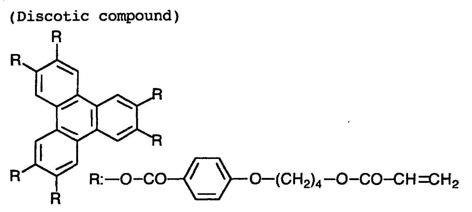
The thus-formed optically anisotropic layer had the
thickness of 1.9 µm. The retardation of the layered composition
of the optically anisotropic layer and the optically
anisotropic transparent support (namely, optical compensatory
sheet) was measured, and as a result the average inclined
angle of the optical axis was found 18.2°, and the
retardation values along the thickness (Rth) and in plane
(Re) were found 156 nm and 33 nm, respectively.
(Preparation of polarizing plate having optically anisotropic
layer)
A stretched polyvinyl alcohol film was made to adsorb
iodine, to prepare a light-absorbing polarizing element.
On one side of the prepared light-absorbing polarizing element,
the layered composition of the optically anisotropic
layer and the optically anisotropic transparent support was
laminated with an adhesive of polyvinyl alcohol type, so
that the optically anisotropic layer might be outside. On
the other side, the light-scattering polarizing element
produced in Example 6 was laminated with the adhesive of
polyvinyl alcohol type, so that the polarizing layer might
be outside.
The transmission axis of the light-absorbing polarizing
element was placed parallel to the slow axis of the
layered composition. Further, the transmission axis of the
light-absorbing polarizing element was placed parallel to
the transmission axis (ne direction) of the element of
light-scattering type. Thus, a polarizing plate having optically
anisotropic layer was produced.
The prepared polarizing plate having optically anisotropic
layer was laminated on a glass plate with an acrylic
adhesive. After aged at a high temperature under a high
pressure, the polarizing plate on the glass plate was left
for 500 hours in a thermostat at 90°C. The polarizing
plate was then observed, and thereby it was confirmed that
troubles such as coming off, bubbling or wrinkling did not
occur. The polarizing plate was further left for another
500 hours (1,000 hours in total) in a thermostat at 90°C.
Even after such treatment, no trouble (such as coming off,
bubbling or wrinkling) was observed on the polarizing plate.
[Example 12]
(Production of liquid crystal display)
On a glass plate having an ITO transparent electrode,
an orientation layer of polyimide was provided and subjected
to a rubbing treatment. This procedure was repeated to
prepare two substrates, and the substrates were arranged
face-to-face so that the rubbing directions might be perpendicular
to each other and that the cell gap might be 5
µm with a spacer between them. Into the gap, a liquid
crystal having Δn of 0.0969 (ZL4792, Merck & Co., Inc.) was
introduced to prepare a liquid crystal layer.
On the backlight side of the thus-prepared liquid
crystal cell of TN mode, the polarizing plate having optically
anisotropic layer produced in Example 11 was laminated.
On the other side, a polarizing plate having optically
anisotropic layer but not having a light-scattering
polarizing element was laminated. Thus, a liquid crystal
display was produced. In the display, the slow axis of the
layered composition of the optically anisotropic layer and
the optically anisotropic support was placed perpendicularly
to the rubbing direction of the liquid crystal cell.
The constitution of the display was as follows.
| Transparent support | (1) |
| Light-absorbing polarizing element | (2) |
| Optically anisotropic transparent support | (3) |
| Optically anisotropic layer | (4) |
| Liquid crystal cell of TN mode | (5) |
| Optically anisotropic layer | (6) |
| Optically anisotropic transparent support | (7) |
| Light-absorbing polarizing element | (8) |
| Transparent support | (9) |
| Light-scattering polarizing element | (10) |
| Backlight | (11) |
Voltage was applied to the liquid crystal cell in the
liquid crystal display, to display a white image at 2V and
a black image at 5V. A ratio of the transmittance
(white/black) was measured as a contrast ratio. The upward-downward,
and leftward-rightward viewing angles giving
contrast ratios of not smaller than 10 without tone inversion
were measured. As a result, the upward-downward and
leftward-rightward viewing angles were found 125° and 165°,
respectively. The front contrast ratio was found 230.
As compared with a liquid crystal display equipped
with a conventional polarizing plate, the obtained display
gave a front brightness improved by about 40%.
[Example 13]
(Production of optically anisotropic transparent support)
At room temperature, 45 weight parts of cellulose acetate
(average acetic acid content: 60.9%), 1.62 weight
parts of the following retardation increasing agent, 232.72
weight parts of methylene chloride, 42.57 weight parts of
methanol and 8.50 weight parts of n-butanol were mixed to
prepare a solution (dope).
The obtained dope was cast by means of a band casting
machine (effective length: 6 m), and dried to form a film
(dry thickness: 100 µm).
The retardation of the formed cellulose acetate film
(optically anisotropic transparent support) was measured at
the wavelength of 550 nm by means of an ellipsometer (M-150,
Japan Spectrum Co., Ltd.), and thereby the retardation values
Re and Rth were found 5 nm and 120 nm, respectively.
An undercoating layer of gelatin was provided on the
optically anisotropic transparent support.
On the gelatin undercoating layer, the coating solution
consisting of the following components was applied in
the amount of 28 ml/cm
2 by means of a wire bar coater of
#16. The coated layer was dried with air at 60°C for 60
seconds, and further dried with air at 90°C for 150 seconds.
The dried layer was then rubbed at the angle of 45° to the
slow axis (measured at 632.8 nm) of the optically anisotropic
transparent support.
| Coating solution for orientation layer |
| The following denatured polyvinyl alcohol | 10 weight parts |
| Water | 371 weight parts |
| Methanol | 119 weight parts |
| Glutaric aldehyde (crosslinking agent) | 0.5 weight part |
To prepare a coating solution, 41.01 g of the discotic
liquid crystal compound used in Example 11, 4.06 g of ethylene
oxide denatured trimethlolpropanetriacrylate (V#360,
Osaka Organic Chemicals Co., Ltd.), 0.90 g of cellulose
acetate butyrate (CAB-551-0.2, Eastman Chemical), 0.23 g of
cellulose acetate butyrate (CAB-551-1, Eastman Chemical),
1.35 g of a photo-polymerization initiator (Irgacure 907,
Ciba-Geigy) and 0.45 g of a sensitizer (Kayacure DETX, Nippon
Kayaku Co., Ltd.) were dissolved in 102 g of methyl
ethyl ketone. The coating solution was then applied on the
orientation layer by means of a wire bar coater of #3. The
thus-treated film was fixed on a metal frame, and maintained
in a thermostat at 130°C for 2 minutes to align the
molecules of the discotic compound. The film was then irradiated
at 130°C for 1 minute with ultraviolet rays emitted
from a high pressure mercury lamp of 120 W/cm, so as to
polymerize the discotic liquid crystal molecules. The film
was cooled to room temperature. Thus, an optically anisotropic
layer was formed.
The Re retardation value was measured at 546 nm, and
found 38 nm. The average angle (average inclined angle)
between the discotic plane and the optically anisotropic
transparent support was found 40°.
(Production of elliptically polarizing plate)
The optically anisotropic transparent support was
soaked in an alkali bath to saponify, and then laminated
with an adhesive on one face of the light-absorbing polarizing
element prepared from polyvinyl alcohol and iodine.
Further, the layered composition of the optically anisotropic
layer and the optically anisotropic transparent support
was laminated with an adhesive on that of the light-absorbing
polarizing element and the optically anisotropic
transparent support, so that both optically anisotropic
transparent supports might be contact with each other.
The transmission axis of the light-absorbing polarizing
element was placed parallel to the slow axes of both
optically anisotropic transparent supports.
On the other side of the light-absorbing polarizing
element, the light-scattering polarizing element was laminated
with an adhesive so that the transmission axis of the
light-absorbing polarizing element might be parallel to
that (ne direction) of the light-scattering polarizing element.
Thus, an elliptically polarizing plate was produced.
(Production of second elliptically polarizing plate)
The above procedure was repeated except that an optically
isotropic film of cellulose triacetate was used in
place of the light-scattering polarizing element, to produce
a second elliptically polarizing plate.
(Production of liquid crystal cell of bend alignment mode)
On a glass plate having an ITO transparent electrode,
an orientation layer of polyimide was provided and subjected
to a rubbing treatment. This procedure was repeated to
prepare two substrates, and the substrates were arranged
face-to-face so that the rubbing directions might be perpendicular
to each other and that the cell gap might be 6
µm with a spacer between them. Into the gap, a liquid
crystal having Δn of 0.1396 (ZLI1132, Merck & Co., Inc.)
was introduced to prepare a liquid crystal cell of bend
alignment mode.
(Production of liquid crystal display)
The liquid crystal cell of bend alignment mode was
sandwiched between the above-prepared elliptically polarizing
plate and the second elliptically polarizing plate.
The elliptically polarizing plate was laminated so that the
light-scattering polarizing element might be on the backlight
side, and the second elliptically polarizing plate
was laminated so that the optically isotropic film of cellulose
triacetate might be on the observer side. The optically
anisotropic layer of each elliptically polarizing
plate was faced to the cell substrate, and the rubbing direction
of the liquid crystal cell was placed anti-parallel
to the rubbing direction of the facing optically anisotropic
layer.
[Example 14]
(Production of transparent support)
A gelatin undercoating layer was formed on a cellulose
triacetate film of 100 µm thickness, to prepare a transparent
support.
The retardation values Re and Rth were measured at 546
nm, and found 0.6 nm and 35 nm, respectively.
(Formation of orientation layer)
On the gelatin undercoating layer, the coating solution
used in Example 13 was applied in the amount of 28
ml/cm2 by means of a wire bar coater of #16. The coated
layer was dried with air at 60°C for 60 seconds, and further
dried with air at 90°C for 150 seconds. The dried
layer was then rubbed at the angle of 45° to the slow axis
(measured at 632.8 nm) of the transparent support.
(Formation of optically anisotropic layer)
To prepare a coating solution, 41.01 g of the discotic
liquid crystal compound used in Example 11, 4.06 g of ethylene
oxide denatured trimethlolpropanetriacrylate (V#360,
Osaka Organic Chemicals Co., Ltd.), 0.90 g of cellulose
acetate butyrate (CAB-551-0.2, Eastman Chemical), 0.23 g of
cellulose acetate butyrate (CAB-551-1, Eastman Chemical),
1.35 g of a photo-polymerization initiator (Irgacure 907,
Ciba-Geigy) and 0.45 g of a sensitizer (Kayacure DETX, Nippon
Kayaku Co., Ltd.) were dissolved in 102 g of methyl
ethyl ketone. The coating solution was then applied on the
orientation layer by means of a wire bar coater of #3. The
thus-treated film was fixed on a metal frame, and maintained
in a thermostat at 130°C for 2 minutes to align the
molecules of the discotic compound. The film was then irradiated
at 130°C for 1 mninute with ultraviolet rays emitted
from a high pressure mercury lamp of 120 W/cm, so as to
polymerize the discotic liquid crystal molecules. The film
was cooled to room temperature. Thus, an optically anisotropic
layer was formed.
The Re retardation value of the optically anisotropic
layer was measured at 546 nm, and found 38 nm. The average
angle (average inclined angle) between the discotic plane
and the transparent support was found 40°.
(Production of elliptically polarizing plate)
The transparent support was soaked in an alkali bath
to saponify, and then laminated with an adhesive on one
face of the light-absorbing polarizing element prepared
from polyvinyl alcohol and iodine. Further, the layered
composition of the optically anisotropic layer and the
transparent support was laminated with an adhesive on that
of the light-absorbing polarizing element and the transparent
support, so that both transparent supports might be
contact with each other.
The transmission axis of the light-absorbing polarizing
element was placed parallel to the slow axes of both
optically anisotropic transparent supports.
On the other side of the light-absorbing polarizing
element, the light-scattering polarizing element was laminated
with an adhesive so that the transmission axis of the
light-absorbing polarizing element might be parallel to
that (ne direction) of the light-scattering polarizing element.
Thus, an elliptically polarizing plate was produced.
(Production of second elliptically polarizing plate)
The above procedure was repeated except that an optically
isotropic film of cellulose triacetate was used in
place of the light-scattering polarizing element, to produce
a second elliptically polarizing plate.
(Production of liquid crystal cell of bend alignment mode)
On a glass plate having an ITO transparent electrode,
an orientation layer of polyimide was provided and subjected
to a rubbing treatment. This procedure was repeated to
prepare two substrates, and the substrates were arranged
face-to-face so that the rubbing directions might be anti-parallel
to each other and that the cell gap might be 3.7
µm with a spacer between them. Into the gap, a liquid
crystal having Δn of 0.0988 (ZLI4792, Merck & Co., Inc.)
was introduced to prepare a liquid crystal cell of horizontal
aligning mode.
(Production of liquid crystal display)
The prepared liquid crystal cell of horizontal aligning
mode was sandwiched between the above-prepared elliptically
polarizing plate and the second elliptically polarizing
plate. The elliptically polarizing plate was laminated
so that the light-scattering polarizing element might be on
the backlight side, and the second elliptically polarizing
plate was laminated so that the optically isotropic film of
cellulose triacetate might be on the observer side. The
optically anisotropic layer of each elliptically polarizing
plate was faced to the cell substrate, and the rubbing direction
of the liquid crystal cell was placed anti-parallel
to the rubbing direction of the facing optically anisotropic
layer.
(Evaluation of liquid crystal display)
The liquid crystal displays produced in Examples 13
and 14 were evaluated with respect to the viewing angle and
the brightness. The results are set forth in Table 1.
| Liquid crystal display | Display mode | Viewing angle
(up/down/left/right) | Brightness |
| Ex. 13 | Bend | 80°/70°/73°/73° | 600 cd |
| Ex. 14 | Horizontal | 75°/45°/56°/55° | 450 cd |
In 40 g of dichloromethane, 7.2 g of a commercially
available rod-like liquid crystal compound (E9, Merck Japan,
Inc.), 0.3 g of polyvinyl cinnamate, 2.4 g of 2-ethylhexyl
acrylate and 0.1 g of a photo-polymerization initiator (Irgacure
907, Ciba-Geigy) were dissolved. The solution was
then filtered through a Teflon filter (porous size: 30 µm),
to prepare a coating solution for polarizing layer.
(Production of light-scattering polarizing element)
A cellulose triacetate film (TAC-TD80U, Fuji Photo
Film Co., Ltd.) having 80 µm thickness was coated with the
coating solution for polarizing layer by means of a bar
coater, dried at 120°C, and exposed to linearly polarized
ultraviolet light (illuminance: 30 mW/cm2, exposure: 400
mJ/cm2) emitted from a polarized ultraviolet light irradiation
machine (Nikon Gijutsu-kobo co., Ltd.) to harden the
coating layer. Thus, a polarizing layer of 15 µm thickness
was formed to produce a light-scattering polarizing element.
(Production of polarizing plate)
The above-produced light-scattering polarizing element
and a commercially available light-absorbing polarizing
element were laminated with an adhesive, to produce a polarizing
plate.
[Example 16]
(Preparation of coating solution for polarizing layer)
In 15.0 g of ethyl acetate, 4.5 g of a rod-like liquid
crystal compound (N26), 0.3 g of a mixture of dipentaerythritolpentaacrylate
and dipentaerythritolhexaacrylate
(DPHA, Nippon Kayaku Co., Ltd.), 0.1 g of a photo-orienting
polymer (PA-1, photo-isomerizing polymer) and 0.1 g of a
photo-polymerization initiator (Irgacure 907, Ciba-Geigy)
were dissolved. The solution was then filtered through a
Teflon filter (porous size: 30 µm), to prepare an optically
anisotropic phase.
Independently, 10 g of gelatin (681, Nitta Gelain Co.,
Ltd.) was dissolved in 90 g of water. To the solution, 0.2
g of sodium docylbenzenesulfonate (surface active agent)
was added and dissolved. The obtained solution was then
filtered through a Teflon filter (porous size: 30 µm), to
prepare an optically isotropic phase.
A mixture of 10 g of the optically anisotropic phase
and 10 g of the optically isotropic phase was heated at
60°C, and dispersed by means of an ultrasonic disperser, to
prepare a coating solution for polarizing layer.
(Production of light-scattering polarizing element)
On a cellulose triacetate film (Fuji Photo Film Co.,
Ltd.) of 100 µm thickness having a gelatin undercoating
layer, the above-prepared coating solution was applied according
to the curtain-coating method. After gelatin was
set at 10°C, the applied solution was dried at 25°C. The
formed layer was then exposed at the incident angle of 45°
to ultraviolet light (illuminance: 200 mW/cm2, exposure:
400 mJ/cm2), which had been emitted from a 160 W/cm air-cooled
metal halide lamp (Eyegraphics Co., Ltd.; wavelength
region: 200 to 500 nm, maximum wavelength: 365 nm) and made
to be parallel rays by collimator. Thereby, the layer was
hardened to form a polarizing layer of 30 µm thickness.
Thus, a light-scattering polarizing element was produced.
(Production of polarizing plate)
The above-produced light-scattering polarizing element
and a commercially available light-absorbing polarizing
element were laminated with an adhesive, to produce a polarizing
plate.
[Example 17]
(Preparation of coating solution for polarizing layer)
In 15.0 g of ethyl acetate, 4.6 g of a photo-orienting
polymer (PA-5, photo-dimerizing polymer), 0.3 g of a mixture
of dipentaerythritolpentaacrylate and dipentaerythritolhexaacrylate
(DPHA, Nippon Kayaku Co., Ltd.) and 0.1 g
of a photo-polymerization initiator (Irgacure 907, Ciba-Geigy)
were dissolved. The solution was then filtered
through a Teflon filter (porous size: 30 µm), to prepare an
optically anisotropic phase.
A mixture of 10 g of the optically anisotropic phase
and 10 g of the optically isotropic phase prepared in Example
16 was heated at 60°C, and dispersed by means of an untrasonic
disperser, to prepare a coating solution for polarizing
layer.
(Production of light-scattering polarizing element)
On a cellulose triacetate film (Fuji Photo Film Co.,
Ltd.) of 80 µm thickness, the above-prepared coating solution
was applied according to the curtain-coating method.
After gelatin was set at 10°C, the applied solution was
dried at 25°C. The formed layer was then exposed to linearly
polarized ultraviolet light (illuminance: 30 mW/cm2,
exposure: 400 mJ/cm2) emitted from a polarized ultraviolet
light irradiation machine (Nikon Gijutsu-kobo co., Ltd.) to
harden the coating layer. Thus, a polarizing layer of 30
µm thickness was formed to produce a light-scattering polarizing
element
(Production of polarizing plate)
The above-produced light-scattering polarizing element
and a commercially available light-absorbing polarizing
element were laminated with an adhesive, to produce a polarizing
plate.
[Comparison Example 1]
(Preparation of coating solution for polarizing layer)
In 40 g of dichloromethane, 7.5 g of a commercially
available rod-like liquid crystal compound (E9, Merck Japan,
Inc.), 2.4 g of 2-ethylhexyl acrylate and 0.1 g of a photo-polymerization
initiator (Irgacure 907, Ciba-Geigy) were
dissolved. The solution was then filtered through a Teflon
filter (porous size: 30 µm), to prepare a coating solution
for polarizing layer.
(Production of light-scattering polarizing element)
A cellulose triacetate film (TAC-TD80U, Fuji Photo
Film Co., Ltd.) having 80 µm thickness was coated with the
coating solution for polarizing layer by means of a bar
coater, dried at 120°C, and exposed to linearly polarized
ultraviolet light (illuminance: 30 mW/cm2, exposure: 400
mJ/cm2) emitted from a polarized ultraviolet light irradiation
machine (Nikon Gijutsu-kobo co., Ltd.) to harden the
coating layer. Thus, a polarizing layer of 15 µm thickness
was formed to produce a light-scattering polarizing element.
(Production of polarizing plate)
The above-produced light-scattering polarizing element
and a commercially available light-absorbing polarizing
element were laminated with an adhesive, to produce a polarizing
plate.
[Comparison Example 2]
The procedure of Example 15 was repeated except that
light was not applied, so as to produce a light-scattering
polarizing element and a polarizing plate.
(Evaluation of light-scattering polarizing element)
1. Refractive index
The refractive indexes of optically anisotropic phase
and optically isotropic phase were measured by means of an
Abbe's refractometer. For measuring the refractive index
of optically anisotropic phase, a liquid mixture of the optically
anisotropic compound and the photo-orienting polymer
was applied on a high refractive glass plate and exposed
to linearly polarized light to align the liquid crystal
molecules. The formed film was then measured to obtain the
refractive index of optically anisotropic phase. On the
other hand, for measuring the refractive index of optically
isotropic phase, the isotropic polymer neat or, if needed,
containing additives was applied on a high refractive glass
plate, and measured to obtain the refractive index of optically
isotropic phase.
The results are set forth in Table 2.
| Light scattering polarizing element | Optically anisotropic compound | Optically isotropic compound |
| | n1 | n2 | n3 |
| Example 15 | 1.78 | 1.53 | 1.53 |
| Example 16 | 1.66 | 1.53 | 1.53 |
| Example 17 | 1.64 | 1.53 | 1.53 |
| Comp. Ex.1 | 1.78 | 1.53 | 1.53 |
| Comp. Ex.2 | 1.78 | 1.53 | 1.53 |
The transmittance and the haze of each prepared light-scattering
polarizing element were measured with a haze mater
(MODEL 1001DP, Nippon Denshoku Kogyo Co., Ltd.). In
the measurement, a polarizer was inserted between the light
source and the element. The measurement was carried out
with the transparent axis of the polarizer placed parallel
or perpendicular to that of the polarizing layer. The
measured values when the axes are parallel are shown as
values in parallel, and those when the axes are perpendicularly
placed are shown as values in perpendicular. The
transmittance was evaluated in terms of that for all rays,
and the scattering degree was evaluated in terms of haze
value. If the element has polarizability, the transmittance
in parallel is higher than that in perpendicular
while the haze in parallel is lower than that in perpendicular.
The results are set forth in Table 3.
3. Surface condition
The element of light-scattering type was inserted between
two polarizers, and the surface condition of the element
was observed while rotated between the polarizers.
The results are set forth in Table 3.
| Light scattering polarizing element | Transmittance for all rays (%) | Haze (%) | Surface condition |
| | Parallel | Perpendicular | Parallel | Perpendicular |
| Example 15 | 85.3 | 46.2 | 5.3 | 82.3 | Uniform |
| Example 16 | 80.2 | 55.7 | 10.2 | 63.8 | Uniform |
| Example 17 | 82.9 | 51.0 | 8.8 | 79.4 | Uniform |
| Comp. Ex.1 | 59.2 | 61.4 | 28.2 | 28.6 | No anisotropy |
| Comp. Ex.2 | 67.4 | 66.3 | 31.8 | 33.3 | No anisotropy |
| (Remarks) No anisotropy: No anisotropy was observed in scattering. |
The polarizing elements of light-scattering type produced
in Examples 15 to 17 exhibited high polarizability.
Each of them had a transmittance of 80% or more in parallel
arrangement while the transmittance in perpendicular arrangement
was 20% or less. Since no color was observed
through each element of Examples 15 to 17 in perpendicular
arrangement, all the light not passing through the element
was presumed to scatter backward. It can be, therefore,
expected that those films can remarkably improve the light
efficiency of liquid crystal display.
The element of Example 16 showed small polarizablity,
as compared with Δn of the used optical anisotropic compound.
The reason of that is because the optical anisotropy
was not fully developed by exposure to light, and hence
it indicates that exposure to linearly polarized light is
preferred.
The elements of Comparison Examples 1 and 2 did not
exhibit polarizability. Because the element of Comparison
Example 1 contained no photo-orienting compound and because
exposure to light was not performed in Comparison Example 2,
molecules of the photo-orienting compound were presumed not
to align in the comparison elements. In fact, they were
observed through a polarizing microscope (×400), to found
random orientation in small domains.
[Example 18]
(Confirmation of improvement of light efficiency)
The polarizing plate produced in Example 17 was placed
on a reflection board of aluminum so that the polarizing
layer might be on the reflection board side, and observed.
As a result, the area covered with the light-scattering polarizing
element was seen brighter. This indicates that
the element improved light efficiency. The reflection
board reflected incident light having passed through the
polarizing plate, and only a part of the reflected light
(light component parallel to the transmission axis of the
polarizing layer) passed through the polarizing layer. The
other component was scattered backward, reflected again by
the reflection board, and reentered the polarizing layer to
improve the efficiency of light.
[Example 19]
The polarizing plate of Example 17 was used to produce
a liquid crystal display having the constitution shown in
Fig.4.
[Comparison Example 3]
A commercially available brightness-increasing film
(DBEF, 3M) having a polarizing layer of optical interference
was used to produce a liquid crystal display having
the constitution shown in Fig.4.
(Evaluation of liquid crystal display)
The liquid crystal display of Example 19 equipped with
a light-scattering polarizing element was observed from the
position right in front of the display, and the display was
also seen obliquely. As a result, brightness was clearly
improved in both observations. On the other hand, the liquid
crystal display of Comparison Example 3 was also observed
in the same manner. As a result, brightness was improved
in the front observation, but not in the oblique observation.
[Example 20]
(Preparation of coating solution for polarizing layer)
In 500 g of 20 wt.% methyl ethyl ketone solution of
polymethyl methacrylate, 400 g of 4'-pentyl-4-biphenylcarbonitrile
was mixed. The mixture was then filtered
through a Teflon filter (porous size: 30 µm), to prepare
a coating solution for polarizing layer.
(Production of light-scattering polarizing element)
The coating solution for polarizing layer was cast onto
a band from a die, and dried to form a film of 40 µm
thickness. The film was peeled from the band, stretched by
1.1 times under dry condition at 25°C, and laminated on a
saponified cellulose triacetate film of 80 µm thickness
(Fuji Photo Film Co., Ltd.) with the adhesive of 5 wt.%
polyvinyl alcohol (PVA117, Kuraray Ltd.) aqueous solution.
The obtained layered film was dried at 120°C to produce a
light-scattering polarizing element.
(Production of polarizing plate)
From a commercially available polarizing plate of iodine
type, the protective film was peeled. In place of the
protective film, the light-scattering polarizing element
was laminated so that the saponified cellulose triacetate
film might be in contact with the polarizing layer containing
iodine. Thus, a polarizing plate was produced.
[Example 21]
(Preparation of coating solution for polarizing layer)
In 1,500 g of 20 wt.% aqueous solution of polyvinyl
alcohol (PVA117, Kuraray Ltd.), 100 g of 4'-pentyl-4-biphenylcarbonitrile
was mixed. The mixture was then dispersed
by means of an ultrasonic disperser to prepare a
coating solution for polarizing layer.
(Production of light-scattering polarizing element)
The coating solution for polarizing layer was cast onto
a band from a die, and dried. When the water content
was 10%, the film was peeled from the band, and laminated
on a saponified cellulose triacetate film of 80 µm thickness
(Fuji Photo Film Co., Ltd.). The obtained layered
film was dried at 120°C to produce a light-scattering polarizing
element.
(Production of polarizing plate)
From a commercially available polarizing plate of iodine
type, the protective film was peeled. In place of the
protective film, the light-scattering polarizing element
was laminated so that the saponified cellulose triacetate
film might be in contact with the polarizing layer containing
iodine. Thus, a polarizing plate was produced.
[Example 22]
(Production of light-scattering polarizing element)
The coating solution for polarizing layer prepared in
Example 21 was cast onto a band from a die, and dried to
form a film of 40 µm thickness. The film was peeled from
the band, stretched by 1.1 times under dry condition at
25°C, and laminated on a saponified cellulose triacetate
film of 80 µm thickness (Fuji Photo Film Co., Ltd.) with
the adhesive of 5 wt.% polyvinyl alcohol (PVA117, Kuraray
Ltd.) aqueous solution. The obtained layered film was
dried at 120°C to produce a light-scattering polarizing
element.
(Production of polarizing plate)
From a commercially available polarizing plate of iodine
type, the protective film was peeled. In place of the
protective film, the light-scattering polarizing element
was laminated so that the saponified cellulose triacetate
film might be in contact with the polarizing layer containing
iodine. Thus, a polarizing plate was produced.
[Example 23]
(Preparation of coating solution for polarizing layer)
In 150 g of ethyl acetate, 48 g of a rod-like liquid
crystal compound (N26), 1.0 g of a mixture of dipentaerythritolpentaacrylate
and dipentaerythritolhexaacrylate
(DPHA, Nippon Kayaku Co., Ltd.) and 1.0 g of a photo-polymerization
initiator (Irgacure 907, Ciba-Geigy) were
dissolved. The solution was then filtered through a polypropylene
filter (porous size: 30 µm), to prepare an optically
anisotropic phase.
Independently, in 2,000 g of 20 wt.% aqueous solution
of polyvinyl alcohol (PVA205, Kuraray Ltd.), 4.0 g of sodium
docylbenzenesulfonate (surface active agent) was added
and dissolved. The obtained solution was then filtered
through a polypropylene filter (porous size: 30 µm), to
prepare an optically isotropic phase.
A mixture of 200 g of the optically anisotropic phase
and 200 g of the optically isotropic phase was dispersed by
means of an ultrasonic disperser, to prepare a coating solution
for polarizing layer.
(Production of light-scattering polarizing element)
On a polyethylene terephthalate film of 6 µm thickness,
the above-prepared coating solution was applied and dried
to prepare a polarizing layer of 30 µm thickness. The support
and the theron-provided polarizing layer were
stretched by 1.25 times under dry condition at 115°C,
ripened at 90°C for 2 minutes, and then exposed to ultraviolet
light (illuminance: 200 mW/cm2, exposure: 400
mJ/cm2), which had been emitted from a 160 W/cm air-cooled
metal halide lamp (Eyegraphics Co., Ltd.; wavelength region:
200 to 500 nm, maximum wavelength: 365 nm), to
hardened the optically anisotropic phase to produce a
light-scattering polarizing element.
(Production of polarizing plate)
From a commercially available polarizing plate of iodine
type, the protective film was peeled. In place of the
protective film, the light-scattering polarizing element
was laminated so that the saponified cellulose triacetate
film might be in contact with the polarizing layer containing
iodine. Thus, a polarizing plate was produced.
[Example 24]
(Preparation of coating solution for polarizing layer)
In 1,500 g of the optically isotropic phase prepared
in Example 23, 100 g of 4'-pentyl-4-biphenylcarbonitrile
was mixed. The mixture was then dispersed by means of an
ultrasonic disperser, to prepare a coating solution for polarizing
layer.
(Production of light-scattering polarizing element)
The coating solution for polarizing layer was cast onto
a band from a die, and dried to form a film of 40 µm
thickness. The film was peeled from the band, stretched by
1.1 times under dry condition at 25°C, and laminated on a
cellulose triacetate film of 100 µm thickness (Fuji Photo
Film Co., Ltd.) having a gelatin undercoating layer with
the adhesive of 5 wt.% polyvinyl alcohol (PVA117, Kuraray
Ltd.) aqueous solution. The obtained layered film was
dried at 120°C to produce a light-scattering polarizing
element.
(Production of polarizing plate)
From a commercially available polarizing plate of iodine
type, the protective film was peeled. In place of the
protective film, the light-scattering polarizing element
was laminated so that the saponified cellulose triacetate
film might be in contact with the polarizing layer containing
iodine. Thus, a polarizing plate was produced.
[Example 25]
(Preparation of coating solution for polarizing layer)
In 1,600 g of water, 100 g of polyvinyl alcohol
(PVA205, Kuraray Ltd.), 300 g of alkyl-denatured polyvinyl
alcohol (MP203, Kuraray Ltd.), 0.2 g of of sodium docylbenzenesulfonate
(surface active agent) and 2.0 g of glycerol
(plasticizer) were dissolved to prepare an optically isotropic
phase.
To 1,500 g of the optically isotropic phase, 100 g of
4'-pentyl-4-biphenylcarbonitrile and 4 g of glutaric aldehyde
was mixed. The mixture was then dispersed by means of
an ultrasonic disperser, to prepare a coating solution for
polarizing layer.
(Production of light-scattering polarizing element)
The coating solution for polarizing layer was cast onto
a band from a die, and dried to form a film of 100 µm
thickness. The film was peeled from the band, stretched by
1.2 times under dry condition at 25°C, and laminated on a
cellulose triacetate film of 80 µm thickness (Fuji Photo
Film Co., Ltd.) with the adhesive of 5 wt.% polyvinyl alcohol
(PVA117, Kuraray Ltd.) aqueous solution. The obtained
layered film was dried at 120°C to produce a light-scattering
polarizing element.
(Production of polarizing plate)
From a commercially available polarizing plate of iodine
type, the protective film was peeled. In place of the
protective film, the light-scattering polarizing element
was laminated so that the saponified cellulose triacetate
film might be in contact with the polarizing layer containing
iodine. Thus, a polarizing plate was produced.
[Example 26]
(Production of light-scattering polarizing element)
The coating solution for polarizing layer prepared in
Example 25 was cast onto a band from a die, and dried to
form a film of 40 µm thickness. The film was peeled from
the band, stretched by 1.1 times under dry condition at
25°C, immersed in 100 g/l boric acid aqueous solution at
70°C for 5 minutes, washed in water at 20°C for 10 seconds,
dried at 80°C for 5 minutes, and laminated on a saponified
cellulose triacetate film (Fuji Photo Film Co., Ltd.) with
the adhesive of 5 wt.% polyvinyl alcohol (PVA117, Kuraray
Ltd.) aqueous solution. The obtained layered film was
dried at 120°C to produce a light-scattering polarizing
element.
(Production of polarizing plate)
From a commercially available polarizing plate of iodine
type, the protective film was peeled. In place of the
protective film, the light-scattering polarizing element
was laminated so that the saponified cellulose triacetate
film might be in contact with the polarizing layer containing
iodine. Thus, a polarizing plate was produced.
[Comparison Example 4]
(Preparation of coating solution for polarizing layer)
In 2,000 g of 5 wt.% methylene chloride solution of
polycarbonate, 400 g of 4'-pentyl-4-biphenylcarbonitrile
was mixed. The mixture was then filtered through a Teflon
filter (porous size: 30 µm), to prepare a coating solution
for polarizing layer.
(Production of light-scattering polarizing element)
The coating solution for polarizing layer was cast onto
a band from a die, and dried to form a film of 40 µm
thickness. The film was peeled from the band, stretched by
1.1 times under dry condition at 25°C, and laminated on a
cellulose triacetate film of 80 µm thickness (Fuji Photo
Film Co., Ltd.) with a commercially available adhesive.
The obtained layered film was dried at 120°C to produce a
light-scattering polarizing element.
(Production of polarizing plate)
From a commercially available polarizing plate of iodine
type, the protective film was peeled. In place of the
protective film, the light-scattering polarizing element
was laminated so that the saponified cellulose triacetate
film might be in contact with the polarizing layer containing
iodine. Thus, a polarizing plate was produced.
[Comparison Example 5]
(Preparation of coating solution for polarizing layer)
In 1,500 g of 20 wt.% aqueous solution of polyvinyl
alcohol (PVA205, Kuraray Ltd.), 100 g of biphenyl was mixed.
The mixture was then dispersed at 70°C by means of an ultrasonic
disperser, to prepare a coating solution for polarizing
layer.
(Production of light-scattering polarizing element)
The coating solution for polarizing layer was cast onto
a band from a die, and dried to form a film of 40 µm
thickness. The film was peeled from the band, stretched by
1.1 times under dry condition at 25°C, and laminated on a
saponified cellulose triacetate film of 80 µm thickness
(Fuji Photo Film Co., Ltd.) with the adhesive of 5 wt.%
polyvinyl alcohol (PVA117, Kuraray Ltd.) aqueous solution.
The obtained layered film was dried at 120°C to produce a
light-scattering polarizing element.
(Production of polarizing plate)
From a commercially available polarizing plate of iodine
type, the protective film was peeled. In place of the
protective film, the light-scattering polarizing element
was laminated so that the saponified cellulose triacetate
film might be in contact with the polarizing layer containing
iodine. Thus, a polarizing plate was produced.
[Comparison Example 6]
The procedure of Example 23 was repeated except that
the film was not stretched, to produce a light-scattering
polarizing element.
(Production of polarizing plate)
From a commercially available polarizing plate of iodine
type, the protective film was peeled. In place of the
protective film, the light-scattering polarizing element
was laminated so that the saponified cellulose triacetate
film might be in contact with the polarizing layer containing
iodine. Thus, a polarizing plate was produced.
(Evaluation of light-scattering polarizing element)
1. Birefringence
The birefringence of the continuous phase was measured.
The film having no discontinuous phase was stretched by a
constant extension ratio, and then the refractive indexes
along MD and TD were measured by means of an Abbe's refractometer.
2. Transmittance and scattering degree (haze)
The transmittance and the haze of each prepared light-scattering
polarizing element were measured with a haze mater
(MODEL 1001DP, Nippon Denshoku Kogyo Co., Ltd.). In
the measurement, a polarizer was inserted between the light
source and the element. The measurement was carried out
with the transparent axis of the polarizer placed parallel
or perpendicular to that of the polarizing layer. The
measured values when the axes are parallel are shown as
values in parallel, and those when the axes are perpendicularly
placed are shown as values in perpendicular. The
transmittance was evaluated in terms of that for all rays,
and the scattering degree was evaluated in terms of haze
value. If the element has polarizability, the transmittance
in parallel is higher than that in perpendicular
while the haze in parallel is lower than that in perpendicular.
3. Particle size of discontinuous phase
The light-scattering polarizing element was cut with a
microtome, and the section was observed by a scanning electron
microscope (×5,000) to take a micrograph. From the
micrograph, 100 particles of the discontinuous phase were
randomly selected and the mean radius of the approximated
circles was measured.
The results were set forth in Table 4. The polarizing
elements of light-scattering type produced in Examples 20
to 26 exhibited high polarizability. Each of them had a
transmittance of 60% or less in parallel arrangement while
the transmittance in perpendicular arrangement was 75% or
more.
The elements of Examples 20 and 23 showed relatively
small polarizablity. The reason of that is because their
discontinuous phases had large sizes. The smaller the mean
particle size of discontinuous phase is, the more the liquid
crystal molecules align. Besides that, the liquid
crystal compound used in Example 23 had such small birefringence
that the element showed small polarizability.
Although the stretching was not performed in Example
21, the element of Example 21 showed polarizability. It
was presumed that the reason of that is because the liquid
crystal molecules were aligned by stress applied in peeling.
The elements of Examples 22, 23, 25 and 26 were left
for 3 days under the condition of high temperature (40°C)
and high humidity (relative humidity: 80%). After that
treatment, the elements of Examples 22 and 25 were remarkably
curled and showed no polarizability. On the other hand,
however, even after that, there was no change in polarizability
of the element of Examples 23. It was presumed
that the reason of that is because the alignment of liquid
crystal molecules was fixed by polymerization of the
molecules in Example 23. The above treatment only slightly
impaired the polarizability of the element of Example 26.
The continuous phase in the element of Example 26 was so
reinforced by crosslinking that it was hardly affected by
humidity.
The elements of Comparison Examples 4 to 6 showed little
polarizability. In the element of Comparison Example 4,
the continuous phase gave such large refringence and had
such a large refractive index in the stretched direction
that the difference between the refractive index of continuous
phase and that of discontinuous phase, namely the
optical anisotropy, was small. In Comparison Example 5, a
liquid crystal compound was not used in the discontinuous
phase, and hence the molecules were little aligned. The
stretching was not performed in Comparison Example 6, and
hence the liquid crystal molecules in the discontinuous
phase were not aligned.
| Light scattering polarizing element | Birefringence | Transmittance for all rays (%) | Haze (%) | Size of discontinuous phase |
| | | Parallel | Perpendicular | Parallel | Perpendicular |
| Example 20 | <0.01 | 56.7 | 78.6 | 78.1 | 34.8 | 2.1 µm |
| Example 21 | <0.01 | 52.5 | 88.8 | 85.5 | 19.0 | 0.3 µm |
| Example 22 | <0.01 | 51.4 | 90.7 | 85.2 | 15.0 | 0.3 µm |
| Example 23 | <0.01 | 58.4 | 80.1 | 74.3 | 27.4 | 1.5 µm |
| Example 24 | <0.01 | 50.5 | 89.6 | 83.1 | 18.8 | 0.3 µm |
| Example 25 | <0.01 | 49.2 | 90.1 | 84.1 | 13.5 | 0.3 µm |
| Example 26 | <0.01 | 48.7 | 90.0 | 83.0 | 13.8 | 0.3 µm |
| Comp. Ex.4 | 0.11 | 72.3 | 75.2 | 39.1 | 42.3 | 2.5 µm |
| Comp. Ex.5 | <0.01 | 82.7 | 89.3 | 24.3 | 7.8 | 0.6 µm |
| Comp. Ex.6 | <0.01 | 78.1 | 80.4 | 36.3 | 31.9 | 1.5 µm |
The coating solution for polarizing layer prepared in
Example 25 was cast onto a band from a die, and dried to
form a film of 40 µm thickness. The film was peeled from
the band, stretched by 1.2 times under dry condition at
25°C, and pressed and laminated without adhesive onto an
iodine-adsorbing polyvinyl alcohol film having been
stretched by 6 times. The obtained layered film was then
immersed in 100 g/l boric acid aqueous solution at 70°C for
5 minutes, washed in water at 20°C for 10 seconds, and
dried at 80°C for 5 minutes. On each of the top and bottom
surfaces of the film, a saponified cellulose triacetate
film (Fuji Photo Film Co., Ltd.) was laminated with the adhesive
of 5 wt.% polyvinyl alcohol (PVA117, Kuraray Ltd.)
aqueous solution. The obtained layered film was dried at
120°C to produce a polarizing plate.
(Evaluation of polarizing plate)
The polarizing plates produced in Examples 26 and 26
and a commericially available polarizing plate (consisting
of a light-absorbing polarizing element alone) were placed
on a reflection board of aluminum so that the polarizing
layer of each plate might be on the reflection board side,
and observed. As a result, the areas covered with the polarizing
plates of Examples 26 and 27 were seen brighter.
This indicates that those plates improved light efficiency.
The reflection board reflected incident light having passed
through each polarizing plate, and only a part of the reflected
light (light component parallel to the transmission
axis of the polarizing layer) passed through the polarizing
layer. The other component was scattered backward, reflected
again by the reflection board, and reentered the
polarizing layer to improve the efficiency of light.
The plates of Examples 26 and 27 were left for 3 days
under the condition of high temperature (40°C) and high humidity
(relative humidity: 80%). That treatment impaired
the increase of brightness of the plate of Examples 26. On
the other hand, however, even after that, there was no
change in brightness of the plate of Examples 27.
[Example 28]
(Production of liquid crystal display)
The polarizing plate of Example 25 was used to produce
a liquid crystal display having the constitution shown in
Fig.3.
[Example 29]
(Production of liquid crystal display)
The polarizing plate of Example 27 was used to produce
a liquid crystal display having the constitution shown in
Fig.4.
(Evaluation of liquid crystal display)
The liquid crystal display of Examples 28 and 29 were
observed from the position right in front of the display,
and the display was also seen obliquely. As a result,
brightness of each plate was improved both in the front observation
and in the oblique observation.