EP1251253A2 - Schaltverband zum Verschluss von Saugkanälen einer Ansaugvorrichtung - Google Patents
Schaltverband zum Verschluss von Saugkanälen einer Ansaugvorrichtung Download PDFInfo
- Publication number
- EP1251253A2 EP1251253A2 EP02007375A EP02007375A EP1251253A2 EP 1251253 A2 EP1251253 A2 EP 1251253A2 EP 02007375 A EP02007375 A EP 02007375A EP 02007375 A EP02007375 A EP 02007375A EP 1251253 A2 EP1251253 A2 EP 1251253A2
- Authority
- EP
- European Patent Office
- Prior art keywords
- passages
- switching
- closure members
- intake
- frame
- Prior art date
- Legal status (The legal status is an assumption and is not a legal conclusion. Google has not performed a legal analysis and makes no representation as to the accuracy of the status listed.)
- Granted
Links
- 238000002485 combustion reaction Methods 0.000 claims description 11
- 238000000465 moulding Methods 0.000 claims description 4
- 238000005516 engineering process Methods 0.000 claims description 3
- 238000002347 injection Methods 0.000 description 4
- 239000007924 injection Substances 0.000 description 4
- 238000009434 installation Methods 0.000 description 4
- 238000004519 manufacturing process Methods 0.000 description 4
- 238000001746 injection moulding Methods 0.000 description 3
- 210000000056 organ Anatomy 0.000 description 2
- 238000007789 sealing Methods 0.000 description 2
- 244000241796 Christia obcordata Species 0.000 description 1
- 230000000712 assembly Effects 0.000 description 1
- 238000000429 assembly Methods 0.000 description 1
- 238000011161 development Methods 0.000 description 1
- 230000018109 developmental process Effects 0.000 description 1
- 230000000694 effects Effects 0.000 description 1
- 239000000463 material Substances 0.000 description 1
Images

Classifications
-
- F—MECHANICAL ENGINEERING; LIGHTING; HEATING; WEAPONS; BLASTING
- F02—COMBUSTION ENGINES; HOT-GAS OR COMBUSTION-PRODUCT ENGINE PLANTS
- F02M—SUPPLYING COMBUSTION ENGINES IN GENERAL WITH COMBUSTIBLE MIXTURES OR CONSTITUENTS THEREOF
- F02M35/00—Combustion-air cleaners, air intakes, intake silencers, or induction systems specially adapted for, or arranged on, internal-combustion engines
- F02M35/10—Air intakes; Induction systems
- F02M35/10006—Air intakes; Induction systems characterised by the position of elements of the air intake system in direction of the air intake flow, i.e. between ambient air inlet and supply to the combustion chamber
- F02M35/10078—Connections of intake systems to the engine
- F02M35/10085—Connections of intake systems to the engine having a connecting piece, e.g. a flange, between the engine and the air intake being foreseen with a throttle valve, fuel injector, mixture ducts or the like
-
- F—MECHANICAL ENGINEERING; LIGHTING; HEATING; WEAPONS; BLASTING
- F02—COMBUSTION ENGINES; HOT-GAS OR COMBUSTION-PRODUCT ENGINE PLANTS
- F02B—INTERNAL-COMBUSTION PISTON ENGINES; COMBUSTION ENGINES IN GENERAL
- F02B27/00—Use of kinetic or wave energy of charge in induction systems, or of combustion residues in exhaust systems, for improving quantity of charge or for increasing removal of combustion residues
- F02B27/02—Use of kinetic or wave energy of charge in induction systems, or of combustion residues in exhaust systems, for improving quantity of charge or for increasing removal of combustion residues the systems having variable, i.e. adjustable, cross-sectional areas, chambers of variable volume, or like variable means
-
- F—MECHANICAL ENGINEERING; LIGHTING; HEATING; WEAPONS; BLASTING
- F02—COMBUSTION ENGINES; HOT-GAS OR COMBUSTION-PRODUCT ENGINE PLANTS
- F02B—INTERNAL-COMBUSTION PISTON ENGINES; COMBUSTION ENGINES IN GENERAL
- F02B27/00—Use of kinetic or wave energy of charge in induction systems, or of combustion residues in exhaust systems, for improving quantity of charge or for increasing removal of combustion residues
- F02B27/02—Use of kinetic or wave energy of charge in induction systems, or of combustion residues in exhaust systems, for improving quantity of charge or for increasing removal of combustion residues the systems having variable, i.e. adjustable, cross-sectional areas, chambers of variable volume, or like variable means
- F02B27/0205—Use of kinetic or wave energy of charge in induction systems, or of combustion residues in exhaust systems, for improving quantity of charge or for increasing removal of combustion residues the systems having variable, i.e. adjustable, cross-sectional areas, chambers of variable volume, or like variable means characterised by the charging effect
- F02B27/0215—Oscillating pipe charging, i.e. variable intake pipe length charging
-
- F—MECHANICAL ENGINEERING; LIGHTING; HEATING; WEAPONS; BLASTING
- F02—COMBUSTION ENGINES; HOT-GAS OR COMBUSTION-PRODUCT ENGINE PLANTS
- F02B—INTERNAL-COMBUSTION PISTON ENGINES; COMBUSTION ENGINES IN GENERAL
- F02B27/00—Use of kinetic or wave energy of charge in induction systems, or of combustion residues in exhaust systems, for improving quantity of charge or for increasing removal of combustion residues
- F02B27/02—Use of kinetic or wave energy of charge in induction systems, or of combustion residues in exhaust systems, for improving quantity of charge or for increasing removal of combustion residues the systems having variable, i.e. adjustable, cross-sectional areas, chambers of variable volume, or like variable means
- F02B27/0226—Use of kinetic or wave energy of charge in induction systems, or of combustion residues in exhaust systems, for improving quantity of charge or for increasing removal of combustion residues the systems having variable, i.e. adjustable, cross-sectional areas, chambers of variable volume, or like variable means characterised by the means generating the charging effect
- F02B27/0247—Plenum chambers; Resonance chambers or resonance pipes
- F02B27/0263—Plenum chambers; Resonance chambers or resonance pipes the plenum chamber and at least one of the intake ducts having a common wall, and the intake ducts wrap partially around the plenum chamber, i.e. snail-type
-
- F—MECHANICAL ENGINEERING; LIGHTING; HEATING; WEAPONS; BLASTING
- F02—COMBUSTION ENGINES; HOT-GAS OR COMBUSTION-PRODUCT ENGINE PLANTS
- F02B—INTERNAL-COMBUSTION PISTON ENGINES; COMBUSTION ENGINES IN GENERAL
- F02B27/00—Use of kinetic or wave energy of charge in induction systems, or of combustion residues in exhaust systems, for improving quantity of charge or for increasing removal of combustion residues
- F02B27/02—Use of kinetic or wave energy of charge in induction systems, or of combustion residues in exhaust systems, for improving quantity of charge or for increasing removal of combustion residues the systems having variable, i.e. adjustable, cross-sectional areas, chambers of variable volume, or like variable means
- F02B27/0226—Use of kinetic or wave energy of charge in induction systems, or of combustion residues in exhaust systems, for improving quantity of charge or for increasing removal of combustion residues the systems having variable, i.e. adjustable, cross-sectional areas, chambers of variable volume, or like variable means characterised by the means generating the charging effect
- F02B27/0268—Valves
- F02B27/0273—Flap valves
-
- F—MECHANICAL ENGINEERING; LIGHTING; HEATING; WEAPONS; BLASTING
- F02—COMBUSTION ENGINES; HOT-GAS OR COMBUSTION-PRODUCT ENGINE PLANTS
- F02M—SUPPLYING COMBUSTION ENGINES IN GENERAL WITH COMBUSTIBLE MIXTURES OR CONSTITUENTS THEREOF
- F02M35/00—Combustion-air cleaners, air intakes, intake silencers, or induction systems specially adapted for, or arranged on, internal-combustion engines
- F02M35/10—Air intakes; Induction systems
- F02M35/10006—Air intakes; Induction systems characterised by the position of elements of the air intake system in direction of the air intake flow, i.e. between ambient air inlet and supply to the combustion chamber
- F02M35/10026—Plenum chambers
- F02M35/10045—Multiple plenum chambers; Plenum chambers having inner separation walls
-
- F—MECHANICAL ENGINEERING; LIGHTING; HEATING; WEAPONS; BLASTING
- F02—COMBUSTION ENGINES; HOT-GAS OR COMBUSTION-PRODUCT ENGINE PLANTS
- F02M—SUPPLYING COMBUSTION ENGINES IN GENERAL WITH COMBUSTIBLE MIXTURES OR CONSTITUENTS THEREOF
- F02M35/00—Combustion-air cleaners, air intakes, intake silencers, or induction systems specially adapted for, or arranged on, internal-combustion engines
- F02M35/10—Air intakes; Induction systems
- F02M35/10006—Air intakes; Induction systems characterised by the position of elements of the air intake system in direction of the air intake flow, i.e. between ambient air inlet and supply to the combustion chamber
- F02M35/10026—Plenum chambers
- F02M35/10052—Plenum chambers special shapes or arrangements of plenum chambers; Constructional details
-
- F—MECHANICAL ENGINEERING; LIGHTING; HEATING; WEAPONS; BLASTING
- F02—COMBUSTION ENGINES; HOT-GAS OR COMBUSTION-PRODUCT ENGINE PLANTS
- F02M—SUPPLYING COMBUSTION ENGINES IN GENERAL WITH COMBUSTIBLE MIXTURES OR CONSTITUENTS THEREOF
- F02M35/00—Combustion-air cleaners, air intakes, intake silencers, or induction systems specially adapted for, or arranged on, internal-combustion engines
- F02M35/10—Air intakes; Induction systems
- F02M35/10006—Air intakes; Induction systems characterised by the position of elements of the air intake system in direction of the air intake flow, i.e. between ambient air inlet and supply to the combustion chamber
- F02M35/10072—Intake runners
-
- F—MECHANICAL ENGINEERING; LIGHTING; HEATING; WEAPONS; BLASTING
- F02—COMBUSTION ENGINES; HOT-GAS OR COMBUSTION-PRODUCT ENGINE PLANTS
- F02M—SUPPLYING COMBUSTION ENGINES IN GENERAL WITH COMBUSTIBLE MIXTURES OR CONSTITUENTS THEREOF
- F02M35/00—Combustion-air cleaners, air intakes, intake silencers, or induction systems specially adapted for, or arranged on, internal-combustion engines
- F02M35/10—Air intakes; Induction systems
- F02M35/10091—Air intakes; Induction systems characterised by details of intake ducts: shapes; connections; arrangements
- F02M35/10111—Substantially V-, C- or U-shaped ducts in direction of the flow path
-
- F—MECHANICAL ENGINEERING; LIGHTING; HEATING; WEAPONS; BLASTING
- F02—COMBUSTION ENGINES; HOT-GAS OR COMBUSTION-PRODUCT ENGINE PLANTS
- F02M—SUPPLYING COMBUSTION ENGINES IN GENERAL WITH COMBUSTIBLE MIXTURES OR CONSTITUENTS THEREOF
- F02M35/00—Combustion-air cleaners, air intakes, intake silencers, or induction systems specially adapted for, or arranged on, internal-combustion engines
- F02M35/10—Air intakes; Induction systems
- F02M35/10242—Devices or means connected to or integrated into air intakes; Air intakes combined with other engine or vehicle parts
- F02M35/10255—Arrangements of valves; Multi-way valves
-
- F—MECHANICAL ENGINEERING; LIGHTING; HEATING; WEAPONS; BLASTING
- F02—COMBUSTION ENGINES; HOT-GAS OR COMBUSTION-PRODUCT ENGINE PLANTS
- F02M—SUPPLYING COMBUSTION ENGINES IN GENERAL WITH COMBUSTIBLE MIXTURES OR CONSTITUENTS THEREOF
- F02M35/00—Combustion-air cleaners, air intakes, intake silencers, or induction systems specially adapted for, or arranged on, internal-combustion engines
- F02M35/10—Air intakes; Induction systems
- F02M35/104—Intake manifolds
- F02M35/108—Intake manifolds with primary and secondary intake passages
-
- F—MECHANICAL ENGINEERING; LIGHTING; HEATING; WEAPONS; BLASTING
- F02—COMBUSTION ENGINES; HOT-GAS OR COMBUSTION-PRODUCT ENGINE PLANTS
- F02M—SUPPLYING COMBUSTION ENGINES IN GENERAL WITH COMBUSTIBLE MIXTURES OR CONSTITUENTS THEREOF
- F02M35/00—Combustion-air cleaners, air intakes, intake silencers, or induction systems specially adapted for, or arranged on, internal-combustion engines
- F02M35/10—Air intakes; Induction systems
- F02M35/104—Intake manifolds
- F02M35/116—Intake manifolds for engines with cylinders in V-arrangement or arranged oppositely relative to the main shaft
-
- F—MECHANICAL ENGINEERING; LIGHTING; HEATING; WEAPONS; BLASTING
- F02—COMBUSTION ENGINES; HOT-GAS OR COMBUSTION-PRODUCT ENGINE PLANTS
- F02B—INTERNAL-COMBUSTION PISTON ENGINES; COMBUSTION ENGINES IN GENERAL
- F02B27/00—Use of kinetic or wave energy of charge in induction systems, or of combustion residues in exhaust systems, for improving quantity of charge or for increasing removal of combustion residues
- F02B27/02—Use of kinetic or wave energy of charge in induction systems, or of combustion residues in exhaust systems, for improving quantity of charge or for increasing removal of combustion residues the systems having variable, i.e. adjustable, cross-sectional areas, chambers of variable volume, or like variable means
- F02B27/0226—Use of kinetic or wave energy of charge in induction systems, or of combustion residues in exhaust systems, for improving quantity of charge or for increasing removal of combustion residues the systems having variable, i.e. adjustable, cross-sectional areas, chambers of variable volume, or like variable means characterised by the means generating the charging effect
- F02B27/0268—Valves
- F02B27/0284—Rotary slide valves
-
- F—MECHANICAL ENGINEERING; LIGHTING; HEATING; WEAPONS; BLASTING
- F02—COMBUSTION ENGINES; HOT-GAS OR COMBUSTION-PRODUCT ENGINE PLANTS
- F02D—CONTROLLING COMBUSTION ENGINES
- F02D9/00—Controlling engines by throttling air or fuel-and-air induction conduits or exhaust conduits
- F02D9/08—Throttle valves specially adapted therefor; Arrangements of such valves in conduits
- F02D9/10—Throttle valves specially adapted therefor; Arrangements of such valves in conduits having pivotally-mounted flaps
- F02D9/109—Throttle valves specially adapted therefor; Arrangements of such valves in conduits having pivotally-mounted flaps having two or more flaps
-
- F—MECHANICAL ENGINEERING; LIGHTING; HEATING; WEAPONS; BLASTING
- F02—COMBUSTION ENGINES; HOT-GAS OR COMBUSTION-PRODUCT ENGINE PLANTS
- F02M—SUPPLYING COMBUSTION ENGINES IN GENERAL WITH COMBUSTIBLE MIXTURES OR CONSTITUENTS THEREOF
- F02M35/00—Combustion-air cleaners, air intakes, intake silencers, or induction systems specially adapted for, or arranged on, internal-combustion engines
- F02M35/10—Air intakes; Induction systems
- F02M35/104—Intake manifolds
- F02M35/112—Intake manifolds for engines with cylinders all in one line
-
- Y—GENERAL TAGGING OF NEW TECHNOLOGICAL DEVELOPMENTS; GENERAL TAGGING OF CROSS-SECTIONAL TECHNOLOGIES SPANNING OVER SEVERAL SECTIONS OF THE IPC; TECHNICAL SUBJECTS COVERED BY FORMER USPC CROSS-REFERENCE ART COLLECTIONS [XRACs] AND DIGESTS
- Y02—TECHNOLOGIES OR APPLICATIONS FOR MITIGATION OR ADAPTATION AGAINST CLIMATE CHANGE
- Y02T—CLIMATE CHANGE MITIGATION TECHNOLOGIES RELATED TO TRANSPORTATION
- Y02T10/00—Road transport of goods or passengers
- Y02T10/10—Internal combustion engine [ICE] based vehicles
- Y02T10/12—Improving ICE efficiencies
Definitions
- the invention relates to a switching assembly for closing suction channels of an intake device an internal combustion engine according to the preamble of claim 1.
- the invention relates to a suction device into which such a switching assembly is installed, according to the preamble of claim 6.
- Switching associations of the type mentioned are known from the prior art.
- an intake system which consists of switching associations, each of two flaps unite with each other in a common flap frame. These individual switching associations are connected to one adjustment unit, which is united by a common Actuating means is driven.
- the switching flaps according to this document are all on one axis.
- assembly injection molding in which the flaps are injected directly into the frame, creating a non-removable functional module arises.
- This manufacturing process is described, for example, in EP 482 272 B1 described in more detail.
- the flap frame is injected with a Passage for the air to be closed by the flap through a corresponding one Core is spared.
- this core becomes one piece pulled apart, creating a cavity into which the valve is injected directly can be.
- the flap edge is not by a molding tool, but by formed the frame itself, whereby tolerances can be completely compensated.
- the shrinkage of the injected valve then causes free mobility the same in the flap frame. Therefore, the materials of the frame and the Do not stick flap together.
- the shrinkage of the flap has the consequence that there is a length offset of several flaps, which are injection molded with a common shaft, added. Therefore, in a structure according to DE 197 35 133, the total is divided Switching device necessary in several switching groups, each with two flaps. More than two flaps cannot be injection molded in one piece, because the shrinkage of the flaps into tension and increased friction of the flaps in the different through openings would lead. The function would be one such switching association seriously endangered.
- the object of the invention is therefore to produce an inexpensive and easy to assemble To create switching association that simultaneously meets the requirements for mobility the closure members and the sealing thereof with respect to that to be closed Through opening optimally fulfilled.
- This task is characterized by the characteristics of the Claim 1 solved.
- the switching assembly according to the invention has a frame in a known manner, in which the passages are provided, which with the suction channels of the suction device communicate. So that the intake air flows through them. A clasp these passages through corresponding closure members thus lead to a Closure of the suction channels.
- the passages can be arranged side by side in the frame in different ways his. An arrangement in a row is conceivable, but an offset arrangement can also be used respectively. This is particularly useful if only part of the passages should be designed to be closable by closure members.
- the closure members are using part of the frame as mold walls and in addition, other molded parts manufactured using original molding technology.
- the assembly injection molding process in which the closure members can be made of plastic.
- the closure organs are in one Cavity injected, which through the molded parts and precisely those partial surfaces of the Frame results with which the closure members are to be engaged. Offer here especially the seating surfaces of the closure member, which at least when closed Closure element with the frame parts forming the passages in the sealing engagement must stand.
- the bearing shafts of the closure members which are necessary to twist the same, in one piece with the closure members manufactured, whereby bearing surfaces form in the frame for the bearing shafts. Indeed the bearing shaft does not have to be mounted directly in the frame. There can also be additional ones Slip rings or the like are used.
- the switching association according to the invention is characterized in that each of the with the Closure members one-piece bearing shafts has its own axis of rotation.
- the individual bearing shafts can accordingly by a common actuating means can be controlled to enable their rotation.
- the main advantage of the invention Design is, however, that all closure members in a single Frame can be injected because of their tolerances due to the shrinkage do not depend on each other by a common shaft. This gives a very inexpensive component to be manufactured, with high tolerance requirements can be fulfilled. This is at the same time the function of the invention Switching association ensured.
- the switching group thus results from the frame and the associated locking elements, injected into them.
- An alternative embodiment of the switching association stipulates that the frames of the locking elements are also manufactured individually. This results in the advantageous saving effect in the manufacture of the closure members. These can be manufactured as a standard component, making production and Tool costs can be saved.
- a support component is also provided, which is used to hold the frames provided with the locking elements serves. In this case too, the individual closure members can be easily controlled given that the bearing shafts each have their own axis of rotation.
- the Both described alternative designs also have the advantage that an addition of Tolerances due to an angular misalignment of the flaps on a common axis of rotation is completely avoided.
- An addition of the tolerances is excluded.
- closure members are switching flaps. These are preferably with a central bearing shaft designed as an axis of rotation and butterfly wings attached to it like a butterfly. On a switching flap of the type described resemble those attacking the flap Forces due to the air flow in the suction device, resulting in low Actuators can be operated.
- closure members consist of rotary valves.
- rotary valves can be cylindrical, for example, the axis of rotation of the closure member exactly in the axis of symmetry of the cylinder lies.
- a passage through the cylinder is provided at right angles to it, whereby this essentially corresponds in cross section to the passage in the frame.
- the passage can be opened and closed by turning the rotary valve.
- Another advantageous variant of the switching association provides that the bearing shafts each at an angle of essentially 90 ° with respect to an imaginary axis parallel to Alignment of the passages runs.
- the bearing shafts In the case of arranging the passages in one Row in the frame are the angles of the bearing shafts compared to the common Bearing shaft rotated by 90 ° according to the prior art. But also with displaced An imaginary axis can be determined by the arrangement of the closure members describes the essential orientation of the passages. The alignment can also do this the bearing shafts have an angle of 90 °.
- the alignment described has the advantage that the individual flaps are special simply by means of an appropriate adjusting device, for example an adjusting rod, can be controlled. You can also set the distance between the neighboring ones This minimizes the locking elements, which means that the shifting assembly is even tight Space can be accommodated.
- a suction device which is intended for the installation of the switching group described is also under protection.
- a switching assembly 10 is shown in FIG. This could, for example, be used as an intermediate flange via mounting holes 11 between the cylinder head of an internal combustion engine (not shown) and the cylinder head flange of an intake manifold (also not shown) to be built in.
- the switching group has passages 12, which with the Communicate suction channels, not shown, of the suction device. Lying there switched and unswitched runs.
- Rotary valves 13 are arranged in the switched passages. These are in one Frame 14a, which forms the switching assembly 10 with them, injected. Im broken Part can be seen that the rotary valve is shown in the open position are. It can also be seen a bearing shaft 15 which penetrates the frame 14a and with a crank for mechanical control of the associated rotary valve 13 is provided.
- FIG. 2 a variant of the switching group according to FIG. 1 is shown.
- This Variant differs in that the rotary valve 13 each in separate frames 14b are injected.
- the carrier component according to FIG. 2 thus fulfills the same purpose when installing in a suction pipe, not shown, as the frame 14a according to Figure 1.
- the rotary valve are shown in this case in the closed state.
- the contour of the frame 14b can be seen more precisely in FIG. These surround the Rotary slide 13 ring-shaped, which creates the association between frame 14b and rotary slide 13 targeted according to the advantages of assembly injection molding can be sealed against each other. Because the rotary valve in the closed position is shown, the passages, which are arranged below the rotary valve are not recognizable.
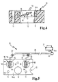
- the circuit arrangement according to FIG. 4 corresponds in structure to that according to FIG. 2, however instead of the rotary valve 13 according to FIG. 2, a switching flap 18 is used comes.
- the bearing shaft 15 of the switching flap and that of the latter can be seen in section outgoing flap wing 19.
- the Switch flap 18 is injection molded into the frame 14b.
- the frame is in the support member 17 used.
- a press fit can be realized, which a reliable mounting of the frame 14b in the carrier component 17 is ensured.
- a switching group with staggered passages 12 is shown.
- a number of the passages are provided with switching flaps 18. These are right in injected the frame 14a.
- An actuating device is also present in FIG. 5 from a push rod 20 and a drive 21.
- the push rod engages via ball joints 22 on the cranks 16 of the switching flaps 18, with one Crank 16a the power of the drive is transmitted to the push rod.
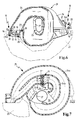
- FIG. 6 shows the installation of a switching group in an intake manifold.
- the switching association is connected to the cylinder head-side outlets 23, the suction channels 24 with connect the schematically represented cylinder head 25 of an internal combustion engine.
- the Suction pipe consists of a collecting space 26, of which the suction channels 24 alternate branch off and run around it in a spiral shape. Therefore, the intake manifold is for one Internal combustion engine with V-arrangement of the cylinders is suitable.
- the actuating device On the side of the intake manifold, not shown in section, there is also the actuating device to recognize that from the components according to Figure 5, the cranks 16, the ball joints 22, the push rod 20 and the drive 21.
- the drive can be realized, for example, by an electric motor.
- Another possibility is the attachment of a vacuum can, for example due to the intake manifold vacuum can be switched.
- an inlet 27 for the combustion air in the collecting space to recognize. Through this the cleaned through the air filter of the intake tract passes Intake air to be distributed over the collecting space 26.
- the switching association is provided with seals 28 to provide a seal against the suction pipe 29 and Ensure cylinder head 25.
- FIG. 7 also shows an intake manifold 29 for an internal combustion engine with a V-shaped arrangement the cylinder shown. This has suction ducts 24a, b of different lengths on. In this way, a so-called power circuit of the intake manifold can be implemented, the shorter suction channels 24b being open at higher speeds. in this connection the switching assembly 10 is used, which has a structure corresponding to FIG. 4.
- the switching assembly is inserted through an indicated mounting opening 30 into the intake manifold and finds its position in the suction channels 24b. These are corresponding the intake manifold in Figure 6 alternately for both cylinder banks of the V-shaped internal combustion engine arranged.
- the individual switching flaps 18 can be activated via the cranks 16 take place.
- the actuator, also through the mounting hole 30 can be installed, as well as the drive 21, which is beyond the assembly opening 30 is not shown.
- the switching assemblies 10 are used for mounting on the suction pipes according to FIGS preassembled.
- the final assembly on the intake manifold can thus be carried out in a simple handling step take place, making the particularly sensitive costs in final assembly small can be held.
- pre-assembly means that the injection-molded parts Switch flap modules, each consisting of flaps 18 and Frame 14b, must be used in the support member 17.
Landscapes
- Engineering & Computer Science (AREA)
- Chemical & Material Sciences (AREA)
- Combustion & Propulsion (AREA)
- Mechanical Engineering (AREA)
- General Engineering & Computer Science (AREA)
- Geometry (AREA)
- Physics & Mathematics (AREA)
- Characterised By The Charging Evacuation (AREA)
- Multiple-Way Valves (AREA)
- Control Of Throttle Valves Provided In The Intake System Or In The Exhaust System (AREA)
- Sheets, Magazines, And Separation Thereof (AREA)
- Massaging Devices (AREA)
- External Artificial Organs (AREA)
Abstract
Description
- Figur 1
- einen Schaltverband mit in einem einzigen Rahmen eingespritzten Drehschiebern in teilweise aufgebrochener Seitenansicht,
- Figur 2
- einen Schaltverband entsprechend Figur 1, wobei die Drehschieber in Einzelrahmen montagespritzgegossen sind, in teilweise aufgebrochener Seitenansicht,
- Figur 3
- die Aufsicht auf den Schaltverband gemäß Figur 2,
- Figur 4
- den Schnitt durch den Teil eines Schaltverbandes, in den ein Schaltklappenmodul mit Einzelrahmen eingebracht ist,
- Figur 5
- die Aufsicht auf einen Schaltverband mit direkt eingespritzten Schaltklappen und Betätigungsgestänge,
- Figur 6
- den Einbau eines Schaltverbandes in der Bauart gemäß Figur 5 in die Saugkanäle eines Saugrohres vor dem Zylinderkopfflansch und
- Figur 7
- den Einbau eines Schaltverbandes entsprechend dem in Figur 4 dargestellten im Inneren eines Saugrohres.
Claims (6)
- Schaltverband (10) zum Verschluss von Saugkanälen (24, 24a, 24b) einer Ansaugvorrichtung einer Brennkraftmaschine, aufweisenddadurch gekennzeichnet, dass jede von mit den Verschlussorganen (13, 16) einteilig hergestellten Lagerwellen (15) eine eigene Drehachse aufweist.einen Rahmen (14a), in dem Durchgänge (12) für die Ansaugluft nebeneinander angeordnet sind, wobei die Durchgänge (12) mit den Saugkanälen korrespondieren,mehrere Verschlussorgane (13, 16), die zumindest in einem Teil der Durchgänge (12) angeordnet sind, wobei diese unter Verwendung von Teilflächen des Rahmens, insbesondere der Durchgänge, als Formwandungen und zusätzlichen weiteren Formteilen in Urformtechnik hergestellt sind,
- Schaltverband (10) zum Verschluss von Saugkanälen (24, 24a, 24b) einer Ansaugvorrichtung einer Brennkraftmaschine mit mehreren Verschlussorganen (13, 16), die in durch Rahmen (14b) für die Verschlussorgane gebildeten Durchgängen (12) angeordnet sind, wobei die Verschlussorgane unter Verwendung von Teilflächen der jeweiligen Rahmen (14b), insbesondere der Durchgänge, als Formwandungen und zusätzlichen weiteren Formteilen in Urformtechnik hergestellt sind,
dadurch gekennzeichnet, dassein Trägerbauteil (17) zur Aufnahme von mehreren Rahmen (14b) mit je einem Durchgang (12) für die Ansaugluft vorgesehen ist, wobei die Rahmen im Trägerbauteil (17) nebeneinander angeordnet sind und wobei die Durchgänge (12) mit den Saugkanälen korrespondieren,jede von mit den Verschlussorganen (13, 16) einteilig hergestellten Lagerwellen (15) eine eigene Drehachse aufweist. - Schaltverband nach einem der vorherigen Ansprüche, dadurch gekennzeichnet, dass die Verschlussorgane aus Schaltklappen bestehen.
- Schaltverband nach einem der Ansprüche 1 oder 2, dadurch gekennzeichnet, dass die Verschlussorgane aus Drehschiebern bestehen.
- Schaltverband nach einem der vorherigen Ansprüche, dadurch gekennzeichnet, dass die mit den Verschlussorganen (13, 16) einteilig hergestellten Lagerwellen (15) jeweils im Winkel von im wesentlichen 90° bezüglich einer gedachten Achse, die parallel zu Ausrichtung der Durchgänge nebeneinander verläuft, angeordnet sind.
- Ansaugvorrichtung für eine Brennkraftmaschine mit einem Einlass (27) sowie zylinderseitigen Auslässen (23) für die Ansaugluft der Brennkraftmaschine, wobei der Einlass (27) in einen Sammelraum (26) mündet, von dem Saugkanäle (24, 24a, 24b) abzweigen, die zu den Auslässen (23) führen, dadurch gekennzeichnet, dass ein Schaltverband gemäß einem der vorherigen Ansprüche in das Saugrohr eingebaut ist, durch den zumindest ein Teil der Saugkanäle mit Hilfe einer Betätigungseinrichtung (16, 20, 21, 22) verschließbar ist.
Applications Claiming Priority (2)
| Application Number | Priority Date | Filing Date | Title |
|---|---|---|---|
| DE10119281 | 2001-04-20 | ||
| DE10119281A DE10119281A1 (de) | 2001-04-20 | 2001-04-20 | Schaltverband zum Verschluss von Saugkanälen einer Ansaugvorrichtung mit diesem Schaltverband |
Publications (3)
| Publication Number | Publication Date |
|---|---|
| EP1251253A2 true EP1251253A2 (de) | 2002-10-23 |
| EP1251253A3 EP1251253A3 (de) | 2003-07-09 |
| EP1251253B1 EP1251253B1 (de) | 2009-01-07 |
Family
ID=7682027
Family Applications (1)
| Application Number | Title | Priority Date | Filing Date |
|---|---|---|---|
| EP02007375A Expired - Lifetime EP1251253B1 (de) | 2001-04-20 | 2002-04-09 | Schaltverband zum Verschluss von Saugkanälen einer Ansaugvorrichtung |
Country Status (5)
| Country | Link |
|---|---|
| US (1) | US6823838B2 (de) |
| EP (1) | EP1251253B1 (de) |
| JP (1) | JP2002364389A (de) |
| AT (1) | ATE420277T1 (de) |
| DE (2) | DE10119281A1 (de) |
Cited By (1)
| Publication number | Priority date | Publication date | Assignee | Title |
|---|---|---|---|---|
| EP1291504A3 (de) * | 2001-09-05 | 2004-06-09 | Pierburg GmbH | Schaltklappeneinrichtung |
Families Citing this family (5)
| Publication number | Priority date | Publication date | Assignee | Title |
|---|---|---|---|---|
| DE10348361B4 (de) * | 2003-10-17 | 2016-02-04 | Volkswagen Ag | Saugrohr für eine Brennkraftmaschine |
| US7543563B2 (en) * | 2007-03-23 | 2009-06-09 | Honda Motor Co., Ltd. | High flow dual throttle body for small displacement engines |
| ATE450706T1 (de) * | 2007-07-30 | 2009-12-15 | Cooper Standard Automotive D | Abgasrückführsystem |
| DE102008055628A1 (de) * | 2008-11-03 | 2010-05-06 | Mann + Hummel Gmbh | Verfahren zur Herstellung eines Klappenverbandes |
| KR101305192B1 (ko) * | 2011-11-10 | 2013-09-12 | 기아자동차주식회사 | 차량용 가변 흡기 시스템 |
Citations (1)
| Publication number | Priority date | Publication date | Assignee | Title |
|---|---|---|---|---|
| DE19735133A1 (de) | 1996-08-29 | 1998-03-05 | Gen Motors Corp | Ventilaufbau für einen Verbrennungsmotor |
Family Cites Families (10)
| Publication number | Priority date | Publication date | Assignee | Title |
|---|---|---|---|---|
| ATE124316T1 (de) | 1990-10-24 | 1995-07-15 | Volvo Ab | Ventilanordnung. |
| DE4038762A1 (de) * | 1990-12-05 | 1992-06-11 | Bosch Gmbh Robert | Stelleinrichtung |
| DE19503771A1 (de) * | 1995-02-04 | 1996-08-08 | Mann & Hummel Filter | Saugmodul |
| FR2743111B1 (fr) * | 1995-12-29 | 1998-02-13 | Renault | Dispositif d'admission pour moteur a combustion interne |
| DE19800207A1 (de) * | 1997-03-20 | 1998-09-24 | Mann & Hummel Filter | Saugmodul |
| FR2774125B1 (fr) * | 1998-01-29 | 2000-03-31 | Peugeot | Dispositif de commande d'ouverture et de fermeture d'au moins un conduit d'air d'une culasse d'un moteur a combustion interne |
| DE19848440A1 (de) * | 1998-10-21 | 2000-04-27 | Mann & Hummel Filter | Klappenmechanismus |
| DE19918777A1 (de) * | 1999-04-24 | 2000-10-26 | Mann & Hummel Filter | Schaltklappenverband aus montagegespritzten Schaltklappen oder Klappenmodulen |
| DE19944623A1 (de) * | 1999-09-17 | 2001-03-22 | Pierburg Ag | Luftansaugkanalsystem für Brennkraftmaschinen |
| US6354267B1 (en) * | 2000-03-28 | 2002-03-12 | Borgwarner Inc. | Injection molded throttle body |
-
2001
- 2001-04-20 DE DE10119281A patent/DE10119281A1/de not_active Ceased
-
2002
- 2002-04-09 AT AT02007375T patent/ATE420277T1/de not_active IP Right Cessation
- 2002-04-09 DE DE50213188T patent/DE50213188D1/de not_active Expired - Lifetime
- 2002-04-09 EP EP02007375A patent/EP1251253B1/de not_active Expired - Lifetime
- 2002-04-19 US US10/125,574 patent/US6823838B2/en not_active Expired - Fee Related
- 2002-04-22 JP JP2002119470A patent/JP2002364389A/ja active Pending
Patent Citations (1)
| Publication number | Priority date | Publication date | Assignee | Title |
|---|---|---|---|---|
| DE19735133A1 (de) | 1996-08-29 | 1998-03-05 | Gen Motors Corp | Ventilaufbau für einen Verbrennungsmotor |
Cited By (1)
| Publication number | Priority date | Publication date | Assignee | Title |
|---|---|---|---|---|
| EP1291504A3 (de) * | 2001-09-05 | 2004-06-09 | Pierburg GmbH | Schaltklappeneinrichtung |
Also Published As
| Publication number | Publication date |
|---|---|
| EP1251253A3 (de) | 2003-07-09 |
| US20020162531A1 (en) | 2002-11-07 |
| DE50213188D1 (de) | 2009-02-26 |
| EP1251253B1 (de) | 2009-01-07 |
| ATE420277T1 (de) | 2009-01-15 |
| US6823838B2 (en) | 2004-11-30 |
| DE10119281A1 (de) | 2002-10-24 |
| JP2002364389A (ja) | 2002-12-18 |
Similar Documents
| Publication | Publication Date | Title |
|---|---|---|
| EP1175556B1 (de) | Schaltklappenverband aus montagegespritzten schaltklappen oder klappenmodulen | |
| DE19735133B4 (de) | Ventilaufbau für einen Verbrennungsmotor | |
| EP1200718B1 (de) | Saugrohranlage | |
| EP0726388A1 (de) | Ansaugsystem | |
| EP1591641A2 (de) | Klappenanordnung im Flanschbereich eines Ansaugsystems einer Brennkraftmaschine | |
| EP0725210A1 (de) | Saugmodul | |
| EP1200722B1 (de) | Drosseleinrichtung mit einer klappe zum einbau in eine flanschverbindung | |
| DE19834835B4 (de) | Kanalsystem, insbesondere Saugrohr für eine Brennkraftmaschine | |
| DE102006000538A1 (de) | Verfahren zum Herstellen einer Ventileinheit | |
| EP1270917A2 (de) | Zwischenflanschsystem für eine direkteinspritzende Brennkraftmaschine | |
| EP1251253B1 (de) | Schaltverband zum Verschluss von Saugkanälen einer Ansaugvorrichtung | |
| DE19834836A1 (de) | Kanalsystem, insbesondere Saugrohr für eine Brennkraftmaschine | |
| EP1105631A1 (de) | Ansaugvorrichtung für eine brennkraftmaschine | |
| EP1233161A2 (de) | Ansaugvorrichtung für eine Brennkraftmaschine und Verfahren zu deren Betrieb | |
| EP0954686B1 (de) | Saugrohr zur steuerung des luftaufwandes im ansaugtrakt einer brennkraftmaschine | |
| DE10143384C1 (de) | Schaltklappeneinrichtung | |
| DE10346763A1 (de) | Saugmodul insbesondere für Brennkraftmaschinen | |
| WO1999020879A2 (de) | Schaltwalze | |
| DE19820245C2 (de) | Ansaugsystem für eine Brennkraftmaschine | |
| DE19861217B4 (de) | Twin Plenum-Sauganlage | |
| DE29913538U1 (de) | Saugrohranlage | |
| DE102004063065A1 (de) | Ventilanordnung zur Führung einer Flüssigkeit gegen das Gasdruckgefälle | |
| DE19536947A1 (de) | Ansauganlage für eine Mehrzylinderbrennkraftmaschine | |
| DE10352781B3 (de) | Luftansaugkanalsystem für eine Verbrennungskraftmaschine | |
| EP1353052A1 (de) | Luftansaugkanalsystem für Brennkraftmaschinen |
Legal Events
| Date | Code | Title | Description |
|---|---|---|---|
| PUAI | Public reference made under article 153(3) epc to a published international application that has entered the european phase |
Free format text: ORIGINAL CODE: 0009012 |
|
| AK | Designated contracting states |
Kind code of ref document: A2 Designated state(s): AT BE CH CY DE DK ES FI FR GB GR IE IT LI LU MC NL PT SE TR |
|
| AX | Request for extension of the european patent |
Free format text: AL;LT;LV;MK;RO;SI |
|
| PUAL | Search report despatched |
Free format text: ORIGINAL CODE: 0009013 |
|
| AK | Designated contracting states |
Designated state(s): AT BE CH CY DE DK ES FI FR GB GR IE IT LI LU MC NL PT SE TR |
|
| AX | Request for extension of the european patent |
Extension state: AL LT LV MK RO SI |
|
| RIC1 | Information provided on ipc code assigned before grant |
Ipc: 7F 02M 35/108 B Ipc: 7F 02B 27/02 A |
|
| 17P | Request for examination filed |
Effective date: 20030728 |
|
| 17Q | First examination report despatched |
Effective date: 20031015 |
|
| RAP1 | Party data changed (applicant data changed or rights of an application transferred) |
Owner name: MANN + HUMMEL GMBH |
|
| AKX | Designation fees paid |
Designated state(s): AT BE CH CY DE DK ES FI FR GB GR IE IT LI LU MC NL PT SE TR |
|
| APBN | Date of receipt of notice of appeal recorded |
Free format text: ORIGINAL CODE: EPIDOSNNOA2E |
|
| APBR | Date of receipt of statement of grounds of appeal recorded |
Free format text: ORIGINAL CODE: EPIDOSNNOA3E |
|
| APAF | Appeal reference modified |
Free format text: ORIGINAL CODE: EPIDOSCREFNE |
|
| APBT | Appeal procedure closed |
Free format text: ORIGINAL CODE: EPIDOSNNOA9E |
|
| GRAP | Despatch of communication of intention to grant a patent |
Free format text: ORIGINAL CODE: EPIDOSNIGR1 |
|
| GRAS | Grant fee paid |
Free format text: ORIGINAL CODE: EPIDOSNIGR3 |
|
| GRAA | (expected) grant |
Free format text: ORIGINAL CODE: 0009210 |
|
| AK | Designated contracting states |
Kind code of ref document: B1 Designated state(s): AT BE CH CY DE DK ES FI FR GB GR IE IT LI LU MC NL PT SE TR |
|
| REG | Reference to a national code |
Ref country code: GB Ref legal event code: FG4D Free format text: NOT ENGLISH |
|
| REG | Reference to a national code |
Ref country code: CH Ref legal event code: EP |
|
| REG | Reference to a national code |
Ref country code: IE Ref legal event code: FG4D Free format text: LANGUAGE OF EP DOCUMENT: GERMAN |
|
| REF | Corresponds to: |
Ref document number: 50213188 Country of ref document: DE Date of ref document: 20090226 Kind code of ref document: P |
|
| PG25 | Lapsed in a contracting state [announced via postgrant information from national office to epo] |
Ref country code: NL Free format text: LAPSE BECAUSE OF FAILURE TO SUBMIT A TRANSLATION OF THE DESCRIPTION OR TO PAY THE FEE WITHIN THE PRESCRIBED TIME-LIMIT Effective date: 20090107 |
|
| NLV1 | Nl: lapsed or annulled due to failure to fulfill the requirements of art. 29p and 29m of the patents act | ||
| PG25 | Lapsed in a contracting state [announced via postgrant information from national office to epo] |
Ref country code: ES Free format text: LAPSE BECAUSE OF FAILURE TO SUBMIT A TRANSLATION OF THE DESCRIPTION OR TO PAY THE FEE WITHIN THE PRESCRIBED TIME-LIMIT Effective date: 20090418 Ref country code: FI Free format text: LAPSE BECAUSE OF FAILURE TO SUBMIT A TRANSLATION OF THE DESCRIPTION OR TO PAY THE FEE WITHIN THE PRESCRIBED TIME-LIMIT Effective date: 20090107 |
|
| REG | Reference to a national code |
Ref country code: IE Ref legal event code: FD4D |
|
| PG25 | Lapsed in a contracting state [announced via postgrant information from national office to epo] |
Ref country code: SE Free format text: LAPSE BECAUSE OF FAILURE TO SUBMIT A TRANSLATION OF THE DESCRIPTION OR TO PAY THE FEE WITHIN THE PRESCRIBED TIME-LIMIT Effective date: 20090407 Ref country code: PT Free format text: LAPSE BECAUSE OF FAILURE TO SUBMIT A TRANSLATION OF THE DESCRIPTION OR TO PAY THE FEE WITHIN THE PRESCRIBED TIME-LIMIT Effective date: 20090608 |
|
| PG25 | Lapsed in a contracting state [announced via postgrant information from national office to epo] |
Ref country code: DK Free format text: LAPSE BECAUSE OF FAILURE TO SUBMIT A TRANSLATION OF THE DESCRIPTION OR TO PAY THE FEE WITHIN THE PRESCRIBED TIME-LIMIT Effective date: 20090107 Ref country code: IE Free format text: LAPSE BECAUSE OF FAILURE TO SUBMIT A TRANSLATION OF THE DESCRIPTION OR TO PAY THE FEE WITHIN THE PRESCRIBED TIME-LIMIT Effective date: 20090107 |
|
| BERE | Be: lapsed |
Owner name: MANN + HUMMEL G.M.B.H. Effective date: 20090430 |
|
| PLBE | No opposition filed within time limit |
Free format text: ORIGINAL CODE: 0009261 |
|
| STAA | Information on the status of an ep patent application or granted ep patent |
Free format text: STATUS: NO OPPOSITION FILED WITHIN TIME LIMIT |
|
| REG | Reference to a national code |
Ref country code: CH Ref legal event code: PL |
|
| 26N | No opposition filed |
Effective date: 20091008 |
|
| GBPC | Gb: european patent ceased through non-payment of renewal fee |
Effective date: 20090409 |
|
| PG25 | Lapsed in a contracting state [announced via postgrant information from national office to epo] |
Ref country code: LI Free format text: LAPSE BECAUSE OF NON-PAYMENT OF DUE FEES Effective date: 20090430 Ref country code: CH Free format text: LAPSE BECAUSE OF NON-PAYMENT OF DUE FEES Effective date: 20090430 |
|
| PG25 | Lapsed in a contracting state [announced via postgrant information from national office to epo] |
Ref country code: GB Free format text: LAPSE BECAUSE OF NON-PAYMENT OF DUE FEES Effective date: 20090409 Ref country code: MC Free format text: LAPSE BECAUSE OF NON-PAYMENT OF DUE FEES Effective date: 20090430 |
|
| PG25 | Lapsed in a contracting state [announced via postgrant information from national office to epo] |
Ref country code: BE Free format text: LAPSE BECAUSE OF NON-PAYMENT OF DUE FEES Effective date: 20090430 |
|
| PG25 | Lapsed in a contracting state [announced via postgrant information from national office to epo] |
Ref country code: AT Free format text: LAPSE BECAUSE OF NON-PAYMENT OF DUE FEES Effective date: 20090409 |
|
| PG25 | Lapsed in a contracting state [announced via postgrant information from national office to epo] |
Ref country code: GR Free format text: LAPSE BECAUSE OF FAILURE TO SUBMIT A TRANSLATION OF THE DESCRIPTION OR TO PAY THE FEE WITHIN THE PRESCRIBED TIME-LIMIT Effective date: 20090408 |
|
| PG25 | Lapsed in a contracting state [announced via postgrant information from national office to epo] |
Ref country code: LU Free format text: LAPSE BECAUSE OF NON-PAYMENT OF DUE FEES Effective date: 20090409 |
|
| PGFP | Annual fee paid to national office [announced via postgrant information from national office to epo] |
Ref country code: DE Payment date: 20110421 Year of fee payment: 10 Ref country code: FR Payment date: 20110510 Year of fee payment: 10 |
|
| PG25 | Lapsed in a contracting state [announced via postgrant information from national office to epo] |
Ref country code: TR Free format text: LAPSE BECAUSE OF FAILURE TO SUBMIT A TRANSLATION OF THE DESCRIPTION OR TO PAY THE FEE WITHIN THE PRESCRIBED TIME-LIMIT Effective date: 20090107 |
|
| PG25 | Lapsed in a contracting state [announced via postgrant information from national office to epo] |
Ref country code: CY Free format text: LAPSE BECAUSE OF FAILURE TO SUBMIT A TRANSLATION OF THE DESCRIPTION OR TO PAY THE FEE WITHIN THE PRESCRIBED TIME-LIMIT Effective date: 20090107 |
|
| PGFP | Annual fee paid to national office [announced via postgrant information from national office to epo] |
Ref country code: IT Payment date: 20110420 Year of fee payment: 10 |
|
| REG | Reference to a national code |
Ref country code: FR Ref legal event code: ST Effective date: 20121228 |
|
| REG | Reference to a national code |
Ref country code: DE Ref legal event code: R119 Ref document number: 50213188 Country of ref document: DE Effective date: 20121101 |
|
| PG25 | Lapsed in a contracting state [announced via postgrant information from national office to epo] |
Ref country code: FR Free format text: LAPSE BECAUSE OF NON-PAYMENT OF DUE FEES Effective date: 20120430 Ref country code: IT Free format text: LAPSE BECAUSE OF NON-PAYMENT OF DUE FEES Effective date: 20120409 |
|
| PG25 | Lapsed in a contracting state [announced via postgrant information from national office to epo] |
Ref country code: DE Free format text: LAPSE BECAUSE OF NON-PAYMENT OF DUE FEES Effective date: 20121101 |