EP1250986A2 - Robot controller including bending compensation means - Google Patents
Robot controller including bending compensation means Download PDFInfo
- Publication number
- EP1250986A2 EP1250986A2 EP02252685A EP02252685A EP1250986A2 EP 1250986 A2 EP1250986 A2 EP 1250986A2 EP 02252685 A EP02252685 A EP 02252685A EP 02252685 A EP02252685 A EP 02252685A EP 1250986 A2 EP1250986 A2 EP 1250986A2
- Authority
- EP
- European Patent Office
- Prior art keywords
- robot
- distal end
- attitude
- determined
- offset
- Prior art date
- Legal status (The legal status is an assumption and is not a legal conclusion. Google has not performed a legal analysis and makes no representation as to the accuracy of the status listed.)
- Ceased
Links
- 238000005452 bending Methods 0.000 title claims abstract description 72
- 238000004364 calculation method Methods 0.000 claims description 30
- 238000012545 processing Methods 0.000 claims description 23
- 230000009466 transformation Effects 0.000 description 16
- 238000000034 method Methods 0.000 description 14
- 239000011159 matrix material Substances 0.000 description 10
- 239000003638 chemical reducing agent Substances 0.000 description 3
- 230000005489 elastic deformation Effects 0.000 description 2
- 238000010586 diagram Methods 0.000 description 1
- 230000006870 function Effects 0.000 description 1
- 230000002093 peripheral effect Effects 0.000 description 1
Images
Classifications
-
- B—PERFORMING OPERATIONS; TRANSPORTING
- B25—HAND TOOLS; PORTABLE POWER-DRIVEN TOOLS; MANIPULATORS
- B25J—MANIPULATORS; CHAMBERS PROVIDED WITH MANIPULATION DEVICES
- B25J9/00—Programme-controlled manipulators
- B25J9/16—Programme controls
- B25J9/1628—Programme controls characterised by the control loop
- B25J9/1638—Programme controls characterised by the control loop compensation for arm bending/inertia, pay load weight/inertia
-
- G—PHYSICS
- G05—CONTROLLING; REGULATING
- G05B—CONTROL OR REGULATING SYSTEMS IN GENERAL; FUNCTIONAL ELEMENTS OF SUCH SYSTEMS; MONITORING OR TESTING ARRANGEMENTS FOR SUCH SYSTEMS OR ELEMENTS
- G05B2219/00—Program-control systems
- G05B2219/30—Nc systems
- G05B2219/39—Robotics, robotics to robotics hand
- G05B2219/39176—Compensation deflection arm
-
- G—PHYSICS
- G05—CONTROLLING; REGULATING
- G05B—CONTROL OR REGULATING SYSTEMS IN GENERAL; FUNCTIONAL ELEMENTS OF SUCH SYSTEMS; MONITORING OR TESTING ARRANGEMENTS FOR SUCH SYSTEMS OR ELEMENTS
- G05B2219/00—Program-control systems
- G05B2219/30—Nc systems
- G05B2219/39—Robotics, robotics to robotics hand
- G05B2219/39186—Flexible joint
-
- G—PHYSICS
- G05—CONTROLLING; REGULATING
- G05B—CONTROL OR REGULATING SYSTEMS IN GENERAL; FUNCTIONAL ELEMENTS OF SUCH SYSTEMS; MONITORING OR TESTING ARRANGEMENTS FOR SUCH SYSTEMS OR ELEMENTS
- G05B2219/00—Program-control systems
- G05B2219/30—Nc systems
- G05B2219/39—Robotics, robotics to robotics hand
- G05B2219/39529—Force, torque sensor in wrist, end effector
Definitions
- the present invention relates to an articulated robot controller.
- the present invention relates to a robot controller capable of obtaining a position/attitude with high accuracy in consideration of the bendings of a robot mechanical section.
- An object of the present invention is to provide a robot controller capable of operating an articulated flexible arm robot at a high speed with a high accuracy by correcting bendings produced in the robot.
- the robot controller having the above structure, it is possible to position the robot to a target position/attitude by correcting the bendings of the entire robot.
- a robot controller for a robot whose respective links are driven by respective actuators and which executes a job by pressing a robot hand distal end against an object includes a sensor for detecting a reaction force produced when the robot hand distal end is pressed against the object; bending calculation means for determining the bendings produced in the respective joints at the target position/attitude of the robot hand distal end based on a teaching program; a robot hand distal end offset calculation means for determining the offset from the target position and/or the offset from the target attitude of the distal end based on the thus determined bendings; and a corrected position calculation means for determining the positions of the actuators for driving the robot hand distal end to a position and/or an attitude to which a correction having the same magnitudes as those of the offset is applied in an inverse direction.
- the robot controller having the above structure, it is possible to maintain the position/attitude of the robot to a target value by correcting the bendings produced when the robot hand distal end is pressed against the object.
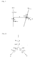
- xt shows the position of the robot hand distal end on a tool coordinate system
- A0 to A6 are 4 ⁇ 4 coordinate transformation matrix.
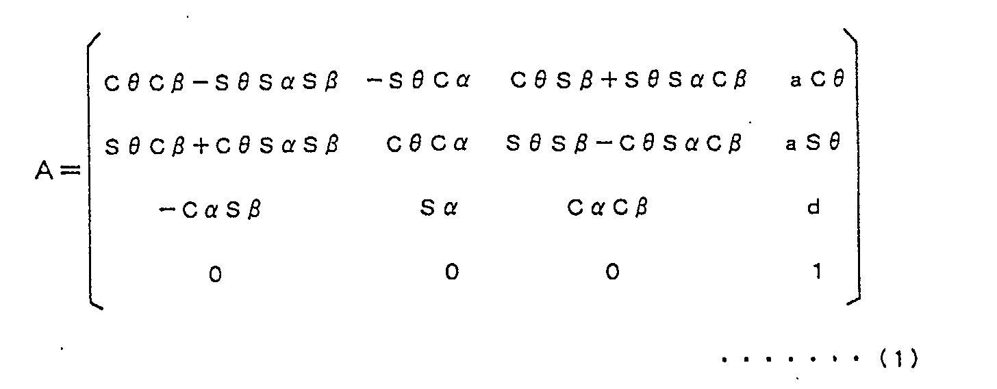
- the corrected D-H parameters (d, a, ⁇ , ⁇ , ⁇ ) are known as parameters showing the coordinate transformation.
- a represents an offset value between axes in an X-axis direction
- d represents an offset value between axes in a Z-axis direction
- ⁇ represents a rotational angle about a Z-axis
- ⁇ represents a rotational angle about an X-axis
- ⁇ represents a rotational angle about a Y-axis as shown in FIG. 1.
- forces and torques applied to the respective joints are determined from the angles and commanded speeds of the respective axes at the time by ignoring spring property using a Newton-Euler method that is widely known as a calculation method of robot dynamics.
- the forces and torques can be determined with a relatively small amount of calculation, although the amount increases in proportion to an increase in the number of axes of a robot.
- the respective axial angles ⁇ are determined from the target position x of the robot hand distal end by executing inverse transformation using the coordinate transformation matrix A shown by the above formula (1) with the corrected D-H parameters ⁇ , ⁇ , and ⁇ 0.
- the rotational angles ⁇ of the respective axes are determined by alternately executing the inverse transformation and the forward transformation until the difference between the position/attitudes of the robot hand distal end converges at a value equal to or less than a predetermined value.
- commanded rotational angles j are determined from the rotational angles ⁇ when the difference converges at the value equal to or less than the predetermined value.
- the rotational angles j permit the robot hand distal end (tool center point) to be moved to a target point in consideration of the twists (bendings) about the X-, Y-, and Z-axes of the joints.
- the above description assumes that elasticity exists about the X-, Y- and Z-axes of the respective joints.
- the target point of the robot hand distal end is determined by the above method in consideration of twist (bending) by creating a dummy coordinate system at the portion and by assuming that the number of axes of the robot is increased by the number of dummy axes provided.
- the above description is made assuming the bending at the link portion as the twist of a joint on a three-dimensional coordinate system.
- the influence of the attitude of the robot that is changed by the bending of the link itself is not taken into consideration in the above description.
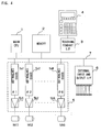
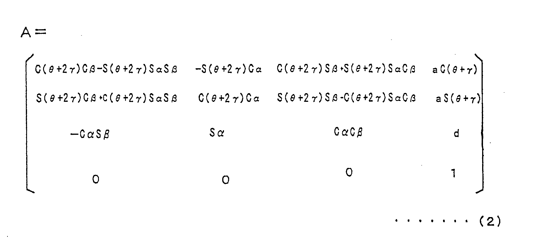
- the twist of the portion of a reducer (joint) is discriminated from the bending over the entire link, and the bending of the entire link is corrected to cope with the influence on the attitude, assuming that it influences the attitude of the robot.
- the link L is bent ⁇ at its joint and also the entire link L is bent uniformly, as shown in FIG. 3, with the result that the link L reaches a position where the distal end point thereof rotates ⁇ .
- the attitude of the link L is further rotated ⁇ as compared with a case in which the link L is approximated by a straight line Q.
- the coordinate transformation matrix A in this case is expressed by the following formula (2).
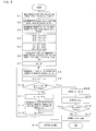
- FIG. 4 is a block diagram of the main portion of the controller for the six-axis vertical articulated robot of the embodiment of the present invention.
- This controller is arranged similarly to a controller for a conventional six-axis vertical articulated robot.
- a main processor 1 a memory 2 composed of a RAM, ROM, non-volatile memory (such as EEPROM), and the like, a teaching pendant interface 3, an external device interface 6, and a servo controller 5 are connected to a bus denoted by a reference numeral 7. Further, a teaching pendant 4 is connected to the teaching pendant interface 3.
- a system program for supporting the basic function of the robot and the robot controller is stored in the ROM of the memory 2. Further, the operation programs and relating set data of the robot that is taught according to an application are stored in the non-volatile memory of the memory 2.
- the RAM of the memory 2 is used as a memory region in which data used in various types of calculation processing executed by the main processor 1 is temporarily stored.
- the servo controller 5 includes servo controllers 5a1 to 5a6 each composed of a processor, ROM, RAM, and the like for executing loop controls of the positions and speeds of servo motors for driving the respective axes and further the loop control of a current.
- the servo controller 5 constitutes a digital servo controller using so-called software to execute loop controls of positions, speeds and current.
- Servo motors M1 to M6 of the respective axes are driven and controlled by the outputs from the servo controllers 5a1 to 5a6 through respective servo amplifiers 5b1 to 5b6.
- position/speed detectors are mounted on the respective servo motors M1 to M6, and the positions and speeds of the respective servo motors detected by the position/speed detectors are fed back to the respective servo controllers 5a1 to 5a6. Further, sensors provided with the robot and the actuators and sensors of a peripheral equipment are connected to an input/output interface 6.
- the robot controller described above is arranged similarly to that of the conventional robot controller.
- it is intended to take the bendings in the joints and links of the robot into consideration and to drive the servo motors M1 to M6 acting as the actuators of the respective axes by correcting the bending components so that the robot hand distal end (tool center point) is accurately driven and controlled according to a target position/attitude.
- FIG. 5 is a flowchart of correction processing executed by the main processor 1 of the robot controller to determine the target position/attitude of the robot hand distal end (tool center point) of the robot in consideration of the bendings of the joints. This processing is executed in a predetermined cycle as long as or longer than a calculation cycle in the servo control. It should be noted that various set values are previously set. Corrected D-H parameters ⁇ s, ⁇ s, and ⁇ 0s, when no twist is produced around the respective axes on the coordinate systems of the respective joints, are previously determined and set by calibration. Further, the spring constants kx, ky, and kz as the rigidity parameters about the respective axes on the coordinate systems of the respective joints are also measured and set previously.
- the rigidity parameters, the moments about the axes of the respective joints, and the position/attitude of the robot hand distal end have the following relationship.
- f (moment, rigidity) robot hand distal end position or attitude
- rigidity f -1 (robot hand distal end position or attitude, moment)
- the robot is operated, the position/attitude of the robot hand distal end is measured, the moments about the respective axes are determined by a Newton-Euler method, or the like, and the rigidity parameters of kx, ky, and kz are determined and set.
- a target position/attitude x commanded at this time that is, a teaching point or an interpolating point x is read (step S1) by executing a teaching program. It is assumed in the embodiment that the position/attitude x is commanded in an orthogonal coordinate system based on a world coordinate system in the teaching program.
- step S2 the angles and actual rotational speeds of the respective joints at this time are read (step S2).
- the torques Tx, Ty, and Tz about the axes of the respective joints are determined using the Newton-Euler method based on the angles and actual rotational speeds of the respective joints which have been read (step S3). Further, the torques Tx, Ty, and Tz about the respective axes are divided by the spring constants kx, ky, and kz of the respective axes of the joints, which have been previously measured and set, respectively, so that the twists, that is, the bendings ⁇ , ⁇ and ⁇ about the X-, Y-, and Z-axes of the respective joints are determined (step S4).
- the corrected D-H parameters ⁇ s, ⁇ s, and ⁇ 0s where no twist is produced are added to the twists (bendings) ⁇ , ⁇ , and ⁇ , respectively, and a corrected D-H parameters ⁇ , ⁇ , and ⁇ 0 in consideration of ⁇ , ⁇ , and ⁇ are determined (step S5).
- a rotational angle ⁇ ' is determined from the target position/attitude x read at step S1 by executing inverse transformation using the corrected D-H parameters ⁇ s, ⁇ s, and ⁇ 0s where no twist is produced, and the rotational angle ⁇ ' is stored as a rotational angle ⁇ st at the beginning of correction (step S6).
- a counter N is set to "0" (step S7), and a position/attitude x' is determined from the rotational angle ⁇ ' determined at step S6 by executing forward transformation using the corrected D-H parameters ⁇ , ⁇ , and ⁇ 0 determined at step S5 (step S8). Then, the target position/attitude x read at step S1 is subtracted from the thus determined position/attitude x' to thereby calculate the difference ⁇ x therebetween (step S9).
- step S10 It is determined whether or not the absolute value of the difference ⁇ x is smaller than a preset reference value T, or whether or not the value of the counter N exceeds a set value Nmax (step S10).
- the difference ⁇ x calculated at step S9 is subtracted from the present target position/attitude x and the result is set as a new target position/attitude x (step S11).
- a rotational angle ⁇ ' is determined from the new target position/attitude x read at step S11 by executing inverse kinematics using the corrected D-H parameters ⁇ s, ⁇ s, and ⁇ 0s, where no twist is produced, again and substituted for the previous rotational angle (step S12). Then, the counter N is counted up by 1 (step S13), and the process returns to step S8.
- step S8 to step S13 is repeatedly executed until it is determined that the absolute value of the difference ⁇ x becomes smaller than the reference value T or that the value of the counter N exceeds the set value Nmax. That is, a new target position/attitude is determined by executing forward kinematics and inverse kinematics alternately, and further the above processing is executed until the absolute value of the difference ⁇ x between the target position/attitude determined previously and the position/attitude newly determined by the forward kinematics becomes smaller than the reference value T.
- step S14 When the absolute value of the difference ⁇ x becomes smaller than the reference value T or the value of the counter N becomes the set value Nmax, the process goes from step S10 to step S14 and stores the rotational angle ⁇ ' determined at that time as a final rotational angle ⁇ (step S14).
- the present difference ⁇ x is displayed (step S15). That is, the differences from the target positions x, y, and z of the robot hand distal end and the differences from the target attitudes w, p, and r thereof are displayed on the display unit of the teaching pendant 4 or on the display unit of a personal computer (not shown) connected to the robot controller (step S15).
- step S6 it is determined whether or not the absolute value of the difference between the final rotational angle ⁇ and the rotational angle ⁇ st at the beginning of correction, determined at step S6, is equal to or larger than a set threshold value ⁇ max (step S16).
- a set threshold value ⁇ max alarm is issued and alarm processing is executed to abruptly stop the robot by applying brake thereto and outputting speed reduction torque commands to the servo motors of the respective axes (step S18).
- a rotational angle j on the teaching pendant is determined by subtracting the initial rotational angle ⁇ 0, determined at step S5, from the final rotational angle ⁇ and stored (step S17).
- the second embodiment is the same as the case in which only the bendings of the joints are taken into consideration as described above except the above points.
- the rotational angle ⁇ ' is stored as a rotational angle ⁇ st at the beginning of correction (corresponding to step S6).
- a position/attitude x' is determined from ⁇ ' by executing forward kinematics by the coordinate transformation matrix A of the formula (2) with the corrected D-H parameters ⁇ , ⁇ , and ⁇ 0 and the value of ⁇ .
- the forward kinematics and the inverse kinematics are alternately executed.
- the difference ⁇ x becomes smaller than the reference value T or the value resultant from the repeated execution of the forward and inverse kinematics exceeds the set value Nmax
- the determined rotational angle ⁇ ' is stored as a final rotational angle ⁇ , and the difference ⁇ x between the target position/attitude and the determined position/attitude is displayed on the display unit. Then, it is determined whether or not the rotational angle ⁇ st at the beginning of rotational angle ⁇ correction processing is equal to or larger than a threshold value ⁇ max.
- a rotational angle to be displayed on a teaching pendant that is, a commanded rotational angle j is determined by subtracting the initial rotational angle ⁇ 0 from the determined rotational angle ⁇ (corresponding to steps S14 to S18).
- the above explanation is for the processing for determining the rotational angles j of the respective joints for positioning the robot to a target position/attitude by taking the bending (twists) of the joints into consideration or by taking the bending (twist) of the joints and also the bending of the links themselves into consideration, and correcting these bendings.
- These processings may be executed in the calculation cycle longer than the calculation cycle for servo control.
- the above processings are executed for a teaching point or an interpolating point as a target commanded position/attitude obtained by executing a teaching program.
- two rotational angles j in which bendings (twists) are corrected are determined by executing the aforementioned processing twice, and data obtained by interpolating between the two rotational angles j is supplied to the servo controllers 5a1 to 5a6 of the respective joints to thereby drive and control the servo motors M1 to M6.
- the twists (bendings) about the X-, Y-, and Z-axes of the coordinate systems of the joints of the robot and further the bending of the links themselves are corrected.
- a dummy coordinate system (joint) is created at the portion, and the aforementioned processings shown in FIG. 5 are executed assuming that the number of axes of the robot is increased.
- a rotational angle j to be commanded is "0" because there is actually no servo motor as an actuator at the dummy portion.
- the axis of the less rigid portion is designated and inputted by the teaching pendant 4. For example, this axis is expressed by a linear formula and inputted. Further, the weight, shape, and the like of the tool are also inputted. Then, the less rigid portion is assumed as a dummy joint based on the linear formula of the axis, and a command for also correcting the bending of the less rigid portion is outputted by the aforementioned method.
- the torques Tx, Ty, and Tz about the respective axes on the coordinate systems of the joints are determined by the calculation using the Newton-Euler method.
- the torques Tx, Ty, and Tz about the respective axes may be detected using a force sensor or a torque sensor.
- the processings at steps S2 and S3 shown in FIG. 5 are executed using the forces or torques obtained by these sensors.
- the present invention can be applied to a burr removing robot in which a robot hand distal end is pressed against an object, wherein the bending produced when the distal end is pressed against the object is corrected.
- a reaction force resulting the pressing operation is detected by the sensors as described above, and the aforementioned correction processings are executed based on the reaction force, thereby the offset of the distal end position of the robot hand made by bending due to external force is also compensated.
- the above embodiments show an example in which a teaching program is programmed at a position on the orthogonal coordinate system.
- the commanded rotational angles j of the respective articulate axes are read at step S1 and transformed to rotational angles ⁇ .
- These rotational angles ⁇ are considered to be rotational angles ⁇ ' and ⁇ st in step S6, and the position/attitude x on the orthogonal coordinate system is determined by executing forward kinematics with the rotational angle ⁇ '.
- Other processings are similar to those shown in FIG. 5.
- the articulated flexible robot can be operated at high speed with high accuracy by correcting the bendings produced in the robot.
- the robot can be operated with further high accuracy by executing correction taking the influence of an attitude that is changed not only by the twists of the joints but also by the bendings of the entire links.
- the robot can be operated with high accuracy also in an application for executing a job by pressing the robot hand distal end.
Landscapes
- Engineering & Computer Science (AREA)
- Robotics (AREA)
- Mechanical Engineering (AREA)
- Manipulator (AREA)
- Numerical Control (AREA)
Abstract
Description
Conventionally, attention is directed to only the rotation about the Z-axis in consideration of only the spring property of a reducer about an axis as a parameter of rigidity. In the present invention, however, it is contemplated that the rotational angles α and β about the X- and Y-axes also have a spring property, and these rotational angles, that is, twists are regarded as bendings. Further, the coordinate transformation matrix A (A1A2 ... A6) where the corrected D-H parameters are used is expressed by the following formula (1).
Claims (10)
- A robot controller for driving respective links of a robot by respective actuators, comprising:bending calculation means for determining the bending produced in the respective joints at the target position/attitude of a robot hand distal end based on a teaching program, or determining the bendings produced in said respective joints and the respective links;robot hand distal end offset calculation means for determining the offset from the target position and/or the offset from the target attitude of the distal end based on the thus determined bendings; andcorrected position calculation means for determining the positions of the actuators for driving the robot hand distal end to a position and/or an attitude to which a correction having the same magnitudes as those of said offset is applied in an inverse direction.
- The robot controller according to claim 1, wherein the bending calculation means determines the bending of the respective joints and the bendings of the links separately.
- The robot controller according to claim 1, wherein said corrected position calculation means determines the positions of the actuators by a converging calculation in which forward kinematics in consideration of the bendings and inverse kinematics ignoring the bending are alternately repeated.
- The robot controller according to claim 1, further comprising means for determining the difference between the positions of the actuators before and after the execution of correction of the bendings, wherein when said difference exceeds a threshold value, alarm processing is executed.
- The robot controller according to claim 1, wherein the corrected position calculation means determines the corrected positions of the actuators in a cycle longer than a calculation cycle for servo control.
- The robot controller according to claim 5, wherein the corrected positions of the actuators determined in the above cycle are internally interpolated and supplied to the actuators of the respective joints as commanded positions.
- The robot controller according to claim 1, comprising means for displaying the offset from the target position of the robot hand distal end determined above and/or the offset from the target attitude of the robot hand distal end determined above.
- The robot controller according to claim 1, further comprising:means for designating an axis where bending is produced in a tool mounted to the robot hand distal end; andmeans for correcting the offset of position and/or the offset of the attitude of the robot hand distal end produced by the bending.
- The robot controller according to claim 1, wherein the optimum values of the rigidity parameters used by the bending calculation means are determined based on the position and/or the attitude of the robot hand distal end assumed when the robot is operated and the moment acting at that time.
- A robot controller for a robot whose respective links are driven by respective actuators and which executes a job by pressing a robot hand distal end against an object, comprising:a sensor for detecting a reaction force produced when pressing the robot hand distal end against the object;bending calculation means for determining the bendings produced in the respective joints at the target position/attitude of the robot hand distal end based on a teaching program;robot hand distal end offset calculation means for determining the offset from the target position and/or the offset from the target attitude of the distal end based on the thus determined bendings; andcorrected position calculation means for determining the positions of the actuators for driving the robot hand distal end to a position and/or an attitude to which a correction having the same magnitudes as those of said offset is applied in an inverse direction.
Applications Claiming Priority (2)
| Application Number | Priority Date | Filing Date | Title |
|---|---|---|---|
| JP2001116693A JP3808321B2 (en) | 2001-04-16 | 2001-04-16 | Robot controller |
| JP2001116693 | 2001-04-16 |
Publications (2)
| Publication Number | Publication Date |
|---|---|
| EP1250986A2 true EP1250986A2 (en) | 2002-10-23 |
| EP1250986A3 EP1250986A3 (en) | 2006-05-17 |
Family
ID=18967390
Family Applications (1)
| Application Number | Title | Priority Date | Filing Date |
|---|---|---|---|
| EP02252685A Ceased EP1250986A3 (en) | 2001-04-16 | 2002-04-16 | Robot controller including bending compensation means |
Country Status (3)
| Country | Link |
|---|---|
| US (1) | US6826450B2 (en) |
| EP (1) | EP1250986A3 (en) |
| JP (1) | JP3808321B2 (en) |
Cited By (32)
| Publication number | Priority date | Publication date | Assignee | Title |
|---|---|---|---|---|
| WO2008095032A3 (en) * | 2007-01-30 | 2008-10-30 | Hansen Medical Inc | Robotic instrument systems controlled using kinematics and mechanics models |
| EP1671759A3 (en) * | 2004-12-08 | 2009-04-15 | Kawasaki Jukogyo Kabushiki Kaisha | Robot controller and robot control method |
| WO2013026554A1 (en) * | 2011-08-24 | 2013-02-28 | Dürr Systems GmbH | Control method for a robot |
| CN105856240A (en) * | 2016-06-14 | 2016-08-17 | 北京邮电大学 | Single-joint fault mechanical arm model rebuilding method based on projection geometric method |
| EP2553386B1 (en) | 2010-03-26 | 2017-10-25 | Leica Geosystems AG | Measuring method for a surface measuring machine |
| CN108025441A (en) * | 2015-09-18 | 2018-05-11 | 川崎重工业株式会社 | Positioning device and positioning method for processing tool |
| WO2018129705A1 (en) * | 2017-01-13 | 2018-07-19 | 中国科学院深圳先进技术研究院 | Method and apparatus for use in determining inverse solution for robots in series connection |
| CN109079850A (en) * | 2018-08-16 | 2018-12-25 | 居鹤华 | Based on axis invariant multi-axis robot D-H system and D-H parameter determination method |
| US10513039B2 (en) | 2016-12-16 | 2019-12-24 | Fanuc Corporation | Teach pendant and robot system provided with the same |
| US10539478B2 (en) | 2017-10-10 | 2020-01-21 | Auris Health, Inc. | Detection of misalignment of robotic arms |
| US10667871B2 (en) | 2014-09-30 | 2020-06-02 | Auris Health, Inc. | Configurable robotic surgical system with virtual rail and flexible endoscope |
| US10765303B2 (en) | 2018-02-13 | 2020-09-08 | Auris Health, Inc. | System and method for driving medical instrument |
| US10765487B2 (en) | 2018-09-28 | 2020-09-08 | Auris Health, Inc. | Systems and methods for docking medical instruments |
| US10806535B2 (en) | 2015-11-30 | 2020-10-20 | Auris Health, Inc. | Robot-assisted driving systems and methods |
| US10813539B2 (en) | 2016-09-30 | 2020-10-27 | Auris Health, Inc. | Automated calibration of surgical instruments with pull wires |
| CN111958602A (en) * | 2020-08-20 | 2020-11-20 | 华中科技大学 | Real-time inverse solution method for wrist offset type 6-axis robot |
| US10912924B2 (en) | 2014-03-24 | 2021-02-09 | Auris Health, Inc. | Systems and devices for catheter driving instinctiveness |
| US10987179B2 (en) | 2017-12-06 | 2021-04-27 | Auris Health, Inc. | Systems and methods to correct for uncommanded instrument roll |
| US11141048B2 (en) | 2015-06-26 | 2021-10-12 | Auris Health, Inc. | Automated endoscope calibration |
| US11298195B2 (en) | 2019-12-31 | 2022-04-12 | Auris Health, Inc. | Anatomical feature identification and targeting |
| US11510736B2 (en) | 2017-12-14 | 2022-11-29 | Auris Health, Inc. | System and method for estimating instrument location |
| US11529129B2 (en) | 2017-05-12 | 2022-12-20 | Auris Health, Inc. | Biopsy apparatus and system |
| US11534247B2 (en) | 2017-06-28 | 2022-12-27 | Auris Health, Inc. | Instrument insertion compensation |
| US11548148B2 (en) | 2019-01-31 | 2023-01-10 | Fanuc Corporation | Robot control device |
| US11602372B2 (en) | 2019-12-31 | 2023-03-14 | Auris Health, Inc. | Alignment interfaces for percutaneous access |
| US11660147B2 (en) | 2019-12-31 | 2023-05-30 | Auris Health, Inc. | Alignment techniques for percutaneous access |
| US11666393B2 (en) | 2017-06-30 | 2023-06-06 | Auris Health, Inc. | Systems and methods for medical instrument compression compensation |
| US11771309B2 (en) | 2016-12-28 | 2023-10-03 | Auris Health, Inc. | Detecting endolumenal buckling of flexible instruments |
| US11925774B2 (en) | 2012-11-28 | 2024-03-12 | Auris Health, Inc. | Method of anchoring pullwire directly articulatable region in catheter |
| US12076100B2 (en) | 2018-09-28 | 2024-09-03 | Auris Health, Inc. | Robotic systems and methods for concomitant endoscopic and percutaneous medical procedures |
| US12414686B2 (en) | 2020-03-30 | 2025-09-16 | Auris Health, Inc. | Endoscopic anatomical feature tracking |
| US12491042B2 (en) | 2013-10-24 | 2025-12-09 | Auris Health, Inc. | Endoscopic device with helical lumen design |
Families Citing this family (59)
| Publication number | Priority date | Publication date | Assignee | Title |
|---|---|---|---|---|
| CA2458979C (en) | 2001-08-31 | 2010-09-28 | George Danko | Coordinated joint motion control system |
| US6973734B2 (en) * | 2002-02-14 | 2005-12-13 | Faro Technologies, Inc. | Method for providing sensory feedback to the operator of a portable measurement machine |
| US6957496B2 (en) * | 2002-02-14 | 2005-10-25 | Faro Technologies, Inc. | Method for improving measurement accuracy of a portable coordinate measurement machine |
| US6952882B2 (en) * | 2002-02-14 | 2005-10-11 | Faro Technologies, Inc. | Portable coordinate measurement machine |
| JP4707306B2 (en) * | 2003-02-28 | 2011-06-22 | 株式会社小坂研究所 | Articulated coordinate measuring device |
| US7145300B2 (en) * | 2003-05-05 | 2006-12-05 | International Rectifier Corporation | Multi-axis AC servo control system and method |
| JP3819883B2 (en) * | 2003-08-27 | 2006-09-13 | ファナック株式会社 | Robot program position correction device |
| DE112005001152T5 (en) * | 2004-05-20 | 2007-06-28 | Abb Research Ltd. | Method and system for retrieving and displaying technical data for an industrial facility |
| WO2006022201A1 (en) * | 2004-08-25 | 2006-03-02 | Kabushiki Kaisha Yaskawa Denki | Robot evaluation system and evaluation method |
| US9110456B2 (en) * | 2004-09-08 | 2015-08-18 | Abb Research Ltd. | Robotic machining with a flexible manipulator |
| JP2006159345A (en) * | 2004-12-07 | 2006-06-22 | Fanuc Ltd | Control device |
| DE102005061618B4 (en) * | 2005-12-21 | 2018-12-27 | Abb Ag | System and method for alignment and position control of a robot tool |
| US8467904B2 (en) * | 2005-12-22 | 2013-06-18 | Honda Motor Co., Ltd. | Reconstruction, retargetting, tracking, and estimation of pose of articulated systems |
| US7859540B2 (en) | 2005-12-22 | 2010-12-28 | Honda Motor Co., Ltd. | Reconstruction, retargetting, tracking, and estimation of motion for articulated systems |
| US8065060B2 (en) * | 2006-01-18 | 2011-11-22 | The Board Of Regents Of The University And Community College System On Behalf Of The University Of Nevada | Coordinated joint motion control system with position error correction |
| US8924021B2 (en) * | 2006-04-27 | 2014-12-30 | Honda Motor Co., Ltd. | Control of robots from human motion descriptors |
| JP2009090403A (en) * | 2007-10-05 | 2009-04-30 | Fanuc Ltd | Robot movement range setting device |
| US8374723B2 (en) * | 2008-12-31 | 2013-02-12 | Intuitive Surgical Operations, Inc. | Obtaining force information in a minimally invasive surgical procedure |
| DE102009032278B4 (en) | 2009-07-08 | 2021-03-04 | Kuka Roboter Gmbh | Method and apparatus for operating a manipulator |
| WO2011021375A1 (en) * | 2009-08-21 | 2011-02-24 | パナソニック株式会社 | Control device and control method for robot arm, assembly robot, control program for robot arm, and integrated electronic circuit for controlling robot arm |
| WO2012142587A1 (en) | 2011-04-15 | 2012-10-18 | Irobot Corporation | Method for path generation for an end effector of a robot |
| JP5482742B2 (en) * | 2011-07-26 | 2014-05-07 | 株式会社安川電機 | Robot manufacturing method |
| JP5921248B2 (en) | 2012-02-16 | 2016-05-24 | キヤノン株式会社 | ROBOT CONTROL DEVICE, ROBOT, PROGRAM THEREOF, AND ITS CONTROL METHOD |
| US9566414B2 (en) | 2013-03-13 | 2017-02-14 | Hansen Medical, Inc. | Integrated catheter and guide wire controller |
| US10849702B2 (en) | 2013-03-15 | 2020-12-01 | Auris Health, Inc. | User input devices for controlling manipulation of guidewires and catheters |
| US9283046B2 (en) | 2013-03-15 | 2016-03-15 | Hansen Medical, Inc. | User interface for active drive apparatus with finite range of motion |
| US11020016B2 (en) | 2013-05-30 | 2021-06-01 | Auris Health, Inc. | System and method for displaying anatomy and devices on a movable display |
| CN103390101B (en) * | 2013-07-15 | 2016-08-10 | 哈尔滨工程大学 | The general method for solving of inverse kinematics of cascade robot |
| JP6226716B2 (en) * | 2013-11-22 | 2017-11-08 | 株式会社ミツトヨ | Arm-type coordinate measuring machine and deflection correction method for arm-type coordinate measuring machine |
| US10682190B2 (en) | 2014-10-27 | 2020-06-16 | Intuitive Surgical Operations, Inc. | System and method for monitoring control points during reactive motion |
| WO2016069648A1 (en) | 2014-10-27 | 2016-05-06 | Intuitive Surgical Operations, Inc. | System and method for integrated surgical table |
| KR102480765B1 (en) | 2014-10-27 | 2022-12-23 | 인튜어티브 서지컬 오퍼레이션즈 인코포레이티드 | Medical device with active brake release control |
| EP4082466B1 (en) * | 2014-10-27 | 2025-07-30 | Intuitive Surgical Operations, Inc. | System for instrument disturbance compensation |
| EP3912610B1 (en) | 2014-10-27 | 2023-03-15 | Intuitive Surgical Operations, Inc. | System for registering to a surgical table |
| CN107072729B (en) | 2014-10-27 | 2020-03-20 | 直观外科手术操作公司 | System and method for integrated surgical table motion |
| JP6700669B2 (en) | 2015-04-07 | 2020-05-27 | キヤノン株式会社 | Control method, robot device, program, recording medium, and article manufacturing method |
| JP2017024142A (en) | 2015-07-27 | 2017-02-02 | ファナック株式会社 | Robot controller for compensating elastic deformation of support |
| WO2017026045A1 (en) * | 2015-08-10 | 2017-02-16 | 富士通株式会社 | Hand-force measurement device, hand-force measurement method, and hand-force measurement program |
| JP6088601B2 (en) | 2015-08-10 | 2017-03-01 | ファナック株式会社 | Robot controller that suppresses tool tip deflection in robot with traveling axis |
| JP6298026B2 (en) | 2015-09-15 | 2018-03-20 | ファナック株式会社 | Deflection measurement system for measuring the deflection of articulated robots |
| JP2017061022A (en) * | 2015-09-25 | 2017-03-30 | 株式会社デンソーウェーブ | Controller of robot |
| US10730191B2 (en) * | 2015-10-30 | 2020-08-04 | Kawasaki Jukogyo Kabushiki Kaisha | Monitoring device of robot system |
| US11037464B2 (en) | 2016-07-21 | 2021-06-15 | Auris Health, Inc. | System with emulator movement tracking for controlling medical devices |
| WO2018109828A1 (en) * | 2016-12-13 | 2018-06-21 | 株式会社Fuji | Method for correcting target position of work robot |
| WO2019012942A1 (en) * | 2017-07-11 | 2019-01-17 | パナソニックIpマネジメント株式会社 | Robot controller |
| JP7314136B2 (en) | 2017-12-08 | 2023-07-25 | オーリス ヘルス インコーポレイテッド | Systems and methods for navigation and targeting of medical instruments |
| US11179213B2 (en) | 2018-05-18 | 2021-11-23 | Auris Health, Inc. | Controllers for robotically-enabled teleoperated systems |
| JP7305951B2 (en) * | 2018-12-14 | 2023-07-11 | ニデック株式会社 | CALIBRATION DEVICE AND CALIBRATION METHOD |
| CN113905853B (en) * | 2019-06-04 | 2024-03-08 | 松下知识产权经营株式会社 | Robot control method |
| CN110434851B (en) * | 2019-06-24 | 2020-11-27 | 浙江工业大学 | A method for solving the inverse kinematics of a 5-DOF manipulator |
| WO2020264418A1 (en) | 2019-06-28 | 2020-12-30 | Auris Health, Inc. | Console overlay and methods of using same |
| CN112415994A (en) * | 2019-08-23 | 2021-02-26 | 佛山群志光电有限公司 | Mobile device and control method thereof |
| CN115515761B (en) * | 2020-05-11 | 2025-07-15 | 发那科株式会社 | Program generation device and program generation method |
| US12220818B2 (en) * | 2020-10-05 | 2025-02-11 | Autodesk, Inc. | Singularity-free kinematic parameterization of soft robot manipulators |
| WO2022075159A1 (en) | 2020-10-06 | 2022-04-14 | ファナック株式会社 | Tool deformation amount calculation device for robot, tool deformation amount calculation system for robot, and tool deformation amount calculation method for robot |
| CN114454155A (en) * | 2020-11-10 | 2022-05-10 | 广东博智林机器人有限公司 | Robot control method, robot control device, computer equipment, medium and robot |
| TWI898086B (en) | 2020-12-16 | 2025-09-21 | 日商發那科股份有限公司 | Command value correction device and robot system |
| JP7543160B2 (en) * | 2021-02-19 | 2024-09-02 | 株式会社神戸製鋼所 | Spring constant correction device, method and program |
| US12097619B2 (en) | 2022-09-26 | 2024-09-24 | Fanuc Corporation | Predictive control method for torque-rate control and vibration suppression |
Family Cites Families (16)
| Publication number | Priority date | Publication date | Assignee | Title |
|---|---|---|---|---|
| US4710884A (en) * | 1984-12-19 | 1987-12-01 | Hitachi Construction Machinery Co., Ltd. | Device for compensating for deflection in a pliable positioning apparatus |
| JPS62242201A (en) | 1986-04-15 | 1987-10-22 | Hitachi Ltd | Control method for industrial robots |
| US4857816A (en) * | 1987-02-05 | 1989-08-15 | Joseph Rogozinski | Precise positioning apparatus |
| JPH04233602A (en) * | 1990-12-28 | 1992-08-21 | Fanuc Ltd | Deflection correcting system for robot |
| JPH0643918A (en) | 1992-05-27 | 1994-02-18 | Mitsubishi Electric Corp | Absolute positioning error correcting device |
| KR0167021B1 (en) * | 1993-03-15 | 1999-02-01 | 카타다 테쯔야 | Automatic grinding apparatus |
| JPH06348322A (en) * | 1993-06-07 | 1994-12-22 | Fanuc Ltd | Off-line teaching method for robot |
| JPH07261821A (en) * | 1994-03-16 | 1995-10-13 | Fanuc Ltd | Robot track planning method taking deflection due to load into consideration |
| US5619111A (en) * | 1995-01-20 | 1997-04-08 | Kabushiki Kaisha Sankyo Seiki Seisakusho | Motor control system for controlling the operations of a plurality of servo motors |
| US5742143A (en) * | 1995-01-20 | 1998-04-21 | Kabushiki Kaisha Sankyo Seiki Seisakusho | Motor control system with selectively operated A/D convertor |
| JP3120028B2 (en) * | 1995-11-02 | 2000-12-25 | 株式会社神戸製鋼所 | Control method for machine having link mechanism |
| JPH09277045A (en) * | 1996-04-12 | 1997-10-28 | Fanuc Ltd | Control method in multi-layer welding |
| JPH10203527A (en) * | 1997-01-20 | 1998-08-04 | Nippon Paper Ind Co Ltd | Easy-to-open paper container |
| US6035242A (en) * | 1997-07-07 | 2000-03-07 | Amada Metrecs Company, Limited | Bending simulation method |
| JPH1177572A (en) | 1997-08-30 | 1999-03-23 | Toyoda Mach Works Ltd | Robot control device |
| JP3215086B2 (en) * | 1998-07-09 | 2001-10-02 | ファナック株式会社 | Robot controller |
-
2001
- 2001-04-16 JP JP2001116693A patent/JP3808321B2/en not_active Expired - Fee Related
-
2002
- 2002-04-16 US US10/122,218 patent/US6826450B2/en not_active Expired - Lifetime
- 2002-04-16 EP EP02252685A patent/EP1250986A3/en not_active Ceased
Cited By (61)
| Publication number | Priority date | Publication date | Assignee | Title |
|---|---|---|---|---|
| EP1671759A3 (en) * | 2004-12-08 | 2009-04-15 | Kawasaki Jukogyo Kabushiki Kaisha | Robot controller and robot control method |
| US7925382B2 (en) | 2004-12-08 | 2011-04-12 | Kawasaki Jukogyo Kabushiki Kaisha | Robot controller and robot control method |
| EP3533410A1 (en) * | 2007-01-30 | 2019-09-04 | Auris Health, Inc. | Robotic instrument systems controlled using kinematics and mechanics models |
| WO2008095032A3 (en) * | 2007-01-30 | 2008-10-30 | Hansen Medical Inc | Robotic instrument systems controlled using kinematics and mechanics models |
| US11454499B2 (en) | 2010-03-26 | 2022-09-27 | Leica Geosystems Ag | Measurement method for a surface-measuring measuring machine |
| EP2553386B1 (en) | 2010-03-26 | 2017-10-25 | Leica Geosystems AG | Measuring method for a surface measuring machine |
| US11796314B2 (en) | 2010-03-26 | 2023-10-24 | Leica Geosystems Ag | Measurement method for a surface-measuring measuring machine |
| EP2553386B2 (en) † | 2010-03-26 | 2025-03-19 | Leica Geosystems AG | Measuring method for a surface measuring machine |
| WO2013026554A1 (en) * | 2011-08-24 | 2013-02-28 | Dürr Systems GmbH | Control method for a robot |
| CN103826807A (en) * | 2011-08-24 | 2014-05-28 | 杜尔系统有限责任公司 | Control method for a robot |
| CN103826807B (en) * | 2011-08-24 | 2017-05-10 | 杜尔系统有限责任公司 | Control method for a robot |
| US9937619B2 (en) | 2011-08-24 | 2018-04-10 | Dürr Systems GmbH | Control method for a robot |
| US11925774B2 (en) | 2012-11-28 | 2024-03-12 | Auris Health, Inc. | Method of anchoring pullwire directly articulatable region in catheter |
| US12350449B2 (en) | 2012-11-28 | 2025-07-08 | Auris Health, Inc. | Method of anchoring pullwire directly articulatable region in catheter |
| US12491042B2 (en) | 2013-10-24 | 2025-12-09 | Auris Health, Inc. | Endoscopic device with helical lumen design |
| US10912924B2 (en) | 2014-03-24 | 2021-02-09 | Auris Health, Inc. | Systems and devices for catheter driving instinctiveness |
| US10667871B2 (en) | 2014-09-30 | 2020-06-02 | Auris Health, Inc. | Configurable robotic surgical system with virtual rail and flexible endoscope |
| US11534250B2 (en) | 2014-09-30 | 2022-12-27 | Auris Health, Inc. | Configurable robotic surgical system with virtual rail and flexible endoscope |
| US12075974B2 (en) | 2015-06-26 | 2024-09-03 | Auris Health, Inc. | Instrument calibration |
| US11141048B2 (en) | 2015-06-26 | 2021-10-12 | Auris Health, Inc. | Automated endoscope calibration |
| EP3351355A4 (en) * | 2015-09-18 | 2019-06-26 | Kawasaki Jukogyo Kabushiki Kaisha | DEVICE AND METHOD FOR POSITIONING A PROCESSING TOOL |
| CN108025441A (en) * | 2015-09-18 | 2018-05-11 | 川崎重工业株式会社 | Positioning device and positioning method for processing tool |
| CN108025441B (en) * | 2015-09-18 | 2021-04-20 | 川崎重工业株式会社 | Positioning device and positioning method of machining tool |
| US11464591B2 (en) | 2015-11-30 | 2022-10-11 | Auris Health, Inc. | Robot-assisted driving systems and methods |
| US10813711B2 (en) | 2015-11-30 | 2020-10-27 | Auris Health, Inc. | Robot-assisted driving systems and methods |
| US10806535B2 (en) | 2015-11-30 | 2020-10-20 | Auris Health, Inc. | Robot-assisted driving systems and methods |
| CN105856240A (en) * | 2016-06-14 | 2016-08-17 | 北京邮电大学 | Single-joint fault mechanical arm model rebuilding method based on projection geometric method |
| US10813539B2 (en) | 2016-09-30 | 2020-10-27 | Auris Health, Inc. | Automated calibration of surgical instruments with pull wires |
| US11712154B2 (en) | 2016-09-30 | 2023-08-01 | Auris Health, Inc. | Automated calibration of surgical instruments with pull wires |
| US12290239B2 (en) | 2016-09-30 | 2025-05-06 | Auris Health, Inc. | Automated calibration of surgical instruments with pull wires |
| US10513039B2 (en) | 2016-12-16 | 2019-12-24 | Fanuc Corporation | Teach pendant and robot system provided with the same |
| US11771309B2 (en) | 2016-12-28 | 2023-10-03 | Auris Health, Inc. | Detecting endolumenal buckling of flexible instruments |
| WO2018129705A1 (en) * | 2017-01-13 | 2018-07-19 | 中国科学院深圳先进技术研究院 | Method and apparatus for use in determining inverse solution for robots in series connection |
| US11529129B2 (en) | 2017-05-12 | 2022-12-20 | Auris Health, Inc. | Biopsy apparatus and system |
| US11534247B2 (en) | 2017-06-28 | 2022-12-27 | Auris Health, Inc. | Instrument insertion compensation |
| US12226176B2 (en) | 2017-06-28 | 2025-02-18 | Auris Health, Inc. | Automatic instrument position adjustment |
| US12076098B2 (en) | 2017-06-30 | 2024-09-03 | Auris Health, Inc. | Systems and methods for medical instrument compression compensation |
| US11666393B2 (en) | 2017-06-30 | 2023-06-06 | Auris Health, Inc. | Systems and methods for medical instrument compression compensation |
| US11796410B2 (en) | 2017-10-10 | 2023-10-24 | Auris Health, Inc. | Robotic manipulator force determination |
| US10539478B2 (en) | 2017-10-10 | 2020-01-21 | Auris Health, Inc. | Detection of misalignment of robotic arms |
| US11280690B2 (en) | 2017-10-10 | 2022-03-22 | Auris Health, Inc. | Detection of undesirable forces on a robotic manipulator |
| US11801105B2 (en) | 2017-12-06 | 2023-10-31 | Auris Health, Inc. | Systems and methods to correct for uncommanded instrument roll |
| US10987179B2 (en) | 2017-12-06 | 2021-04-27 | Auris Health, Inc. | Systems and methods to correct for uncommanded instrument roll |
| US11510736B2 (en) | 2017-12-14 | 2022-11-29 | Auris Health, Inc. | System and method for estimating instrument location |
| US10765303B2 (en) | 2018-02-13 | 2020-09-08 | Auris Health, Inc. | System and method for driving medical instrument |
| US12029390B2 (en) | 2018-02-13 | 2024-07-09 | Auris Health, Inc. | System and method for driving medical instrument |
| CN109079850A (en) * | 2018-08-16 | 2018-12-25 | 居鹤华 | Based on axis invariant multi-axis robot D-H system and D-H parameter determination method |
| CN109079850B (en) * | 2018-08-16 | 2020-01-07 | 居鹤华 | D-H system and D-H parameter determination method of multi-axis robot based on axis invariance |
| US10765487B2 (en) | 2018-09-28 | 2020-09-08 | Auris Health, Inc. | Systems and methods for docking medical instruments |
| US12076100B2 (en) | 2018-09-28 | 2024-09-03 | Auris Health, Inc. | Robotic systems and methods for concomitant endoscopic and percutaneous medical procedures |
| US12226175B2 (en) | 2018-09-28 | 2025-02-18 | Auris Health, Inc. | Systems and methods for docking medical instruments |
| US11497568B2 (en) | 2018-09-28 | 2022-11-15 | Auris Health, Inc. | Systems and methods for docking medical instruments |
| US11548148B2 (en) | 2019-01-31 | 2023-01-10 | Fanuc Corporation | Robot control device |
| US12220150B2 (en) | 2019-12-31 | 2025-02-11 | Auris Health, Inc. | Aligning medical instruments to access anatomy |
| US11602372B2 (en) | 2019-12-31 | 2023-03-14 | Auris Health, Inc. | Alignment interfaces for percutaneous access |
| US11660147B2 (en) | 2019-12-31 | 2023-05-30 | Auris Health, Inc. | Alignment techniques for percutaneous access |
| US12414823B2 (en) | 2019-12-31 | 2025-09-16 | Auris Health, Inc. | Anatomical feature tracking |
| US12465431B2 (en) | 2019-12-31 | 2025-11-11 | Auris Health, Inc. | Alignment techniques for percutaneous access |
| US11298195B2 (en) | 2019-12-31 | 2022-04-12 | Auris Health, Inc. | Anatomical feature identification and targeting |
| US12414686B2 (en) | 2020-03-30 | 2025-09-16 | Auris Health, Inc. | Endoscopic anatomical feature tracking |
| CN111958602A (en) * | 2020-08-20 | 2020-11-20 | 华中科技大学 | Real-time inverse solution method for wrist offset type 6-axis robot |
Also Published As
| Publication number | Publication date |
|---|---|
| EP1250986A3 (en) | 2006-05-17 |
| US20020173878A1 (en) | 2002-11-21 |
| JP2002307344A (en) | 2002-10-23 |
| US6826450B2 (en) | 2004-11-30 |
| JP3808321B2 (en) | 2006-08-09 |
Similar Documents
| Publication | Publication Date | Title |
|---|---|---|
| US6826450B2 (en) | Robot controller | |
| EP0519081B1 (en) | Method of correcting deflection of robot | |
| US7508155B2 (en) | Controller | |
| US9211646B2 (en) | Control apparatus and control method for robot arm, assembly robot, control program for robot arm, and control-purpose integrated electronic circuit for robot arm | |
| US4899095A (en) | Robot control system | |
| EP1431854B1 (en) | Robot controller | |
| JP2023080195A (en) | ROBOT, PRODUCT MANUFACTURING METHOD, CONTROL METHOD, CONTROL PROGRAM, RECORDING MEDIUM | |
| JP6700669B2 (en) | Control method, robot device, program, recording medium, and article manufacturing method | |
| CN101678551B (en) | Motion Controllers for Elastic Robotic Structures | |
| US6127792A (en) | Control apparatus for robot | |
| US20040128030A1 (en) | Robot control apparatus and method | |
| US20210053218A1 (en) | Robot controller | |
| US5637969A (en) | Vibration control method | |
| JP2010058256A (en) | Arm position regulating method and apparatus and robot system | |
| US20200101604A1 (en) | Robot controller | |
| JPH07319547A (en) | Tracer control method for robot | |
| JPH11134012A (en) | Robot with track error correcting function | |
| JP3577124B2 (en) | Method of acquiring mating data using force control robot | |
| JP7543160B2 (en) | Spring constant correction device, method and program | |
| JP7310271B2 (en) | CONTROL DEVICE, CONTROL METHOD, AND ROBOT SYSTEM | |
| JP7227018B2 (en) | Learning controller, robot controller and robot | |
| JP2832903B2 (en) | Coordinate switching method for scanning control | |
| JPH074781B2 (en) | How to reproduce the posture of the robot jig | |
| JPH08263128A (en) | Method for acceleration and deceleration control at positioning control time of robot | |
| JP2751967B2 (en) | Copying control device |
Legal Events
| Date | Code | Title | Description |
|---|---|---|---|
| PUAI | Public reference made under article 153(3) epc to a published international application that has entered the european phase |
Free format text: ORIGINAL CODE: 0009012 |
|
| AK | Designated contracting states |
Kind code of ref document: A2 Designated state(s): AT BE CH CY DE DK ES FI FR GB GR IE IT LI LU MC NL PT SE TR |
|
| AX | Request for extension of the european patent |
Free format text: AL;LT;LV;MK;RO;SI |
|
| PUAL | Search report despatched |
Free format text: ORIGINAL CODE: 0009013 |
|
| AK | Designated contracting states |
Kind code of ref document: A3 Designated state(s): AT BE CH CY DE DK ES FI FR GB GR IE IT LI LU MC NL PT SE TR |
|
| AX | Request for extension of the european patent |
Extension state: AL LT LV MK RO SI |
|
| 17P | Request for examination filed |
Effective date: 20061113 |
|
| 17Q | First examination report despatched |
Effective date: 20061222 |
|
| AKX | Designation fees paid |
Designated state(s): DE |
|
| RAP1 | Party data changed (applicant data changed or rights of an application transferred) |
Owner name: FANUC CORPORATION |
|
| APBK | Appeal reference recorded |
Free format text: ORIGINAL CODE: EPIDOSNREFNE |
|
| APBN | Date of receipt of notice of appeal recorded |
Free format text: ORIGINAL CODE: EPIDOSNNOA2E |
|
| APBR | Date of receipt of statement of grounds of appeal recorded |
Free format text: ORIGINAL CODE: EPIDOSNNOA3E |
|
| APAF | Appeal reference modified |
Free format text: ORIGINAL CODE: EPIDOSCREFNE |
|
| APBT | Appeal procedure closed |
Free format text: ORIGINAL CODE: EPIDOSNNOA9E |
|
| STAA | Information on the status of an ep patent application or granted ep patent |
Free format text: STATUS: THE APPLICATION HAS BEEN REFUSED |
|
| 18R | Application refused |
Effective date: 20151217 |