EP1250883B1 - Optometry apparatus comprising a diffraction grating plate - Google Patents
Optometry apparatus comprising a diffraction grating plate Download PDFInfo
- Publication number
- EP1250883B1 EP1250883B1 EP02090150A EP02090150A EP1250883B1 EP 1250883 B1 EP1250883 B1 EP 1250883B1 EP 02090150 A EP02090150 A EP 02090150A EP 02090150 A EP02090150 A EP 02090150A EP 1250883 B1 EP1250883 B1 EP 1250883B1
- Authority
- EP
- European Patent Office
- Prior art keywords
- cylindrical
- degree
- axis
- diffraction grating
- axial angle
- Prior art date
- Legal status (The legal status is an assumption and is not a legal conclusion. Google has not performed a legal analysis and makes no representation as to the accuracy of the status listed.)
- Expired - Lifetime
Links
- 230000003287 optical effect Effects 0.000 claims abstract description 111
- 238000012937 correction Methods 0.000 claims abstract description 49
- 238000005259 measurement Methods 0.000 claims description 34
- 239000011159 matrix material Substances 0.000 claims description 13
- 238000000034 method Methods 0.000 description 18
- 239000002131 composite material Substances 0.000 description 14
- 238000012360 testing method Methods 0.000 description 9
- 230000004438 eyesight Effects 0.000 description 7
- 230000008859 change Effects 0.000 description 4
- 201000009310 astigmatism Diseases 0.000 description 2
- 238000003780 insertion Methods 0.000 description 2
- 230000037431 insertion Effects 0.000 description 2
- 230000000737 periodic effect Effects 0.000 description 2
- 206010020675 Hypermetropia Diseases 0.000 description 1
- 230000004308 accommodation Effects 0.000 description 1
- 230000004075 alteration Effects 0.000 description 1
- 230000003247 decreasing effect Effects 0.000 description 1
- 238000000691 measurement method Methods 0.000 description 1
- 208000001491 myopia Diseases 0.000 description 1
- 230000009467 reduction Effects 0.000 description 1
- 230000004044 response Effects 0.000 description 1
Images


Classifications
-
- A—HUMAN NECESSITIES
- A61—MEDICAL OR VETERINARY SCIENCE; HYGIENE
- A61B—DIAGNOSIS; SURGERY; IDENTIFICATION
- A61B3/00—Apparatus for testing the eyes; Instruments for examining the eyes
- A61B3/02—Subjective types, i.e. testing apparatus requiring the active assistance of the patient
- A61B3/028—Subjective types, i.e. testing apparatus requiring the active assistance of the patient for testing visual acuity; for determination of refraction, e.g. phoropters
- A61B3/032—Devices for presenting test symbols or characters, e.g. test chart projectors
Definitions
- the present invention relates to an optometry apparatus having an optical element by which targets can be seen as if they were dispersed in a plane orthogonal to an optical axis and presented simultaneously at a different distance or position in a direction of an optical axis through examined eyes to be subjected to optometry, and a diffraction grating plate as an optical element used in the same.
- an optometry apparatus makes a precise decision of an astigmatic axis of examined eyes to be subjected to optometry and of an astigmatic degree by use of a cross cylinder lens.
- a cross cylinder method and an auto-cross cylinder method are known.
- a spherical degree S, a cylindrical degree C, and an axial angle A of a cylindrical axis O are roughly measured, thereafter, the astigmatic axis of the examined eyes to be subjected to optometry and the astigmatic degree are precisely measured.
- a spherical lens 2 whose the spherical degree S is, for example, +3.00D, which is higher than a prospective degree, is set to an optometric window of a correction optical system 1 by fogging, and an eyesight-test chart is shown to a subject.
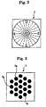
- an astigmatic test chart 8 illustrated in Fig. 2 is shown to the subject at the stage which is one step before desirable eyesight, and the subject is asked how the astigmatic test chart 3 is seen.
- the astigmatic test chart 3 is blurredly seen uniformly, it can be judged that the subject is not a person with astigmatism.
- the subject is a person with astigmatism.
- a cylindrical lens 4 is set to the optometric window of the correction optical system 1 and the cylindrical axis O is set in a direction orthogonal to a direction where clear vision can be obtained.
- the axial angle A of cylindrical axis O is set to 90 degrees.
- the cylindrical degree C of the cylindrical lens 4 to be set to the optometric window is increased 0.25 by 0.25, and the approximate measurement is completed when the degree of the cylindrical lens 4 reaches a value where the astigmatic test chart 3 is clearly seen uniformly.
- reference numeral O1 denotes an optical axis of the correction optical system 1.
- a cross cylindrical lens 5 is inserted in the correction optical system 1.
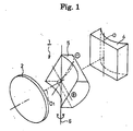
- This cross cylinder lens 5 is structured such that the axis of(-) axial cylindrical lens is orthogonal to that of (+) axial cylindrical lens as shown in Fig. 1.
- an intermediate axis 6 of the cross cylindrical lens 5 is allowed to conform to the cylindrical axis O of the cylindrical lens 4.
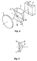
- the cross cylindrical lens 5 is reversed using the intermediate axis 6 of the cross cylindrical lens 5 as a central axis. Then, the subject is allowed to look at a point group chart 7 of Fig. 3.
- the cylindrical lens 4 and cross cylindrical lens 5 are integrally rotated in a direction where a clear view is obtained by, for example 5 degrees to measure the axial angle A of the cylindrical lens 4 precisely.
- any one of (+) axis and (-) axis of the cross cylindrical lens 5 is confirmed to the cylindrical axis O of the cylindrical lens 4.
- Fig. 4 shows a state in which (+) axis is confirmed, to the cylindrical axis 0.
- the point group chart of Fig. 3 is shown to the subject.
- the cross cylinder lens 5 is reversed using the intermediate axis 6 as a central axis and the (-) axis is conformed to the cylindrical axis O.
- the point group chart of Fig. 3 is shown to the subject.
- the cylindrical degree C of the cylindrical lens 2 is set to a direction where a clear view can be obtained.
- an auto cross cylindrical lens 8 shown in Fig. 5 is used.
- This auto cross cylindrical lens 8 includes a triangular prism 9 and cross cylindrical lenses 10, 11.
- the cross cylindrical lenses 10 and 11 have the degree of, for example, ⁇ 0. 25D or ⁇ 0.5D, and plus and minus axes of the cross cylindrical lenses 10 and 11 are orthogonal with respect to each other.
- an intermediate axis 12 of the auto cross cylindrical lens 8 is confirmed to the cylindrical axis O of the cylindrical lens 4 as shown in Fig. 6. Consequently, the plus axis (+) of the upper-side cross cylinder lens 10 is set to a direction at 45 degrees with respect to the cylindrical axis 0 and the minus axis (-) thereof is set to a direction at 135 degrees. Moreover, the minus axis (-) of the lower-side cross cylinder lens 11 is set to a direction at 45 degrees with respect to the cylindrical axis O and the plus axis (+) thereof is set to a direction at 135 degrees.
- the point group chart 7 of Fig. 3 is similarly shown to the subject so that the subject is allowed to perform comparison between the point group chart 7 seen through the upper-side cross cylinder lens 10 and the point group chart 7 seen through the lower-side cross cylinder lens 11 simultaneously to check which chart can be clearly seen.
- the cylindrical lens 4 is rotated integrally with the auto cross cylinder 8 in the direction where a good view can be obtained.
- the axial angle A of the cylindrical axis O is decided.
- the cross cylinder lenses 10 and 11 are rotated so that the plus axis (+) of the cross cylinder lens 10 is conformed to the cylindrical axis O and the minus (-) of the cross cylinder lens 11 is conformed to the cylindrical axis O as illustrated in Fig. 7.
- the cylindrical degree C of the cylindrical lens 4 which is inserted in the optical path of the correction optical system 1, is changed to the direction where the good view can be obtained.
- a so-called red and green chart 13 is shown as illustrated in Fig. 8.
- the spherical degree S of the spherical lens 2 is increased.
- the spherical degree S of the spherical lens 2 is decreased.
- the subject can easily judge which the target can be seen well as compared with the case of using the cross cylinder method.
- this auto cross cylinder method has a disadvantage in which the spherical degree S, cylindrical degree C and axial angle A of cylindrical axis cannot be measured simultaneously.
- many subjects answer that the subject can see more easily the respective points 7a whose profile lines 7b are clearly seen in the direction of astigmatic axis as illustrated in a partially enlarged view of Fig. 9, as compared with the respective points 7a of point group chart 7 of Fig. 3 which are blurredly seen uniformly.
- US-A-5914772 Discloses a device for testing eyes which comprises an autorefractor, an autolensometer, an autophoropter, a display device, an input device, a printing device, and a computer interfacing with each of the components.
- This testing device can be used for performing a method comprising the steps of obtaining autorefractor, corrected autorefractor, and autolenscmeter results; calculating sphere; performing a Red-Green test; calculating cylinder and axis; determining minimum cylinder power; determining final sphere; and recording all data.
- the present invention has been made with consideration given to the aforementioned problems and it is an object of the present invention is to provide an optometry apparatus that can measure a spherical degree S, a cylindrical degree C and an axial angle A of a cylindrical axis O at one time, so that targets are seen as if they were dispersed in a plane orthogonal to an optical axis and shown simultaneously at a different distance or position in a direction of the optical axis.
- An optometry apparatus comprises a spherical lens, a cylindrical lens and optical element constructed so that targets appear to examined eyes to be subjected to optometry as if the targets were dispersed on a plane orthogonal to an optical axis and shown simultaneously at a different distance or position in a direction of the optical axis, wherein the optical element is formed of a diffraction grating plate where periodicity of a diffraction grating changes.
- the diffraction grating plate is capable of going/coming to/from an optical path of the correction optical system.
- the targets are shown by a.point light source with a single color.
- a subject himself/herself designates a target, which seems to be the best among the plurality of targets shown simultaneously and adjusts said correction optical system.
- matrix signs which can designate the plurality of targets in the form of matrix, are simultaneously shown to the eyes to be subjected to optometry such that the subject himself/herself is caused to designate the target, which seems to be the best among the plurality of targets shown simultaneously.
- the matrix sings are shown in an optical path of the correction optical system through a half mirror, or the matrix signs are shown with a wavelength by which no diffraction power is generated.
- the subject himself/herself adjusts the correction optical system using a joystick such an target, which seems to be the best among the plurality of targets shown simultaneously, is positioned on an optical axis of the correction optical system.
- the diffraction grating plate is rotated together with the cylindrical lens, so that a spherical degree, a cylindrical degree and an axial angle of a cylindrical axis are precisely measured.
- the diffraction grating plate is rotated by 45 degrees from an initial setting state to determine a spherical degree, a cylindrical degree and an axial angle of a cylindrical axis by calculation.
- a spherical degree, a cylindrical degree and an axial angle of a cylindrical axis are determined by the calculation are synthesized with a cylindrical degree and an axial angle of a cylindrical axis determined by approximate measurement.
- the spherical degree, the cylindrical degree and the axial angle of cylindrical axis are precisely measured by the synthesized spherical degree, cylindrical degree, and axial angel of cylindrical axis obtained by this calculation.
- the diffraction grating plate is rotated by 60 degrees two times from am initial setting state to determine a spherical degree, a cylindrical degree and an axial angle of a cylindrical axis by calculation.
- a spherical degree, a cylindrical degree and an axis angle of a cylindrical axis are determined by calculation where the spherical degree, the cylindrical degree and the axial angle of cylindrical axis determined by the calculation are synthesized with a spherical degree, a cylindrical degree and an axial angle of a cylindrical axis determined by approximate measurement.
- the spherical degree, the cylindrical degree and the axial angle of cylindrical axis are precisely measured by the synthesized spherical degree, cylindrical degree, and axial angle of cylindrical axis determined by this calculation.
- a pin hole plate having a point target is provided between the point light source with a single color and the diffraction grating plate.
- Fig. 10 is an explanatory view showing a schematic structure of an optometry apparatus according to the present invention.
- reference numeral 20 is an , 21 is a subject, 22 is a target presenting apparatus, 23 is a Phoroptor, and 24 is a controller.
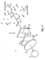
- the Phoroptor 23 is provided with a spherical lens 24 having a different spherical degree S, a cylindrical lens 25 having a different cylindrical degree C and a diffraction grating plate 26 as an optical element as shown in Fig. 11. These spherical lens 24, cylindrical lens 25 and diffraction grating plate 26 are set to an optometric window of the Phoroptor 23 as required.
- Fig. 11 shows a state in which approximate measurement of a spherical degree S, a cylindrical degree C and an axial angle A with respect to examined eyes E subjected to optometry is finished and the spherical lens 24 and the cylindrical lens 25, which serve as correction optical system 1, are inserted in the optometry window.
- the axial angle A of the cylindrical axis O of the cylindrical lens 25 is set to 90 degrees similar to the conventional case.
- the diffraction grating plate 26 is used to carry out precise measurement of an astigmatic axis of the eyes to be subjected to optometry, an astigmatic degree, and a spherical degree.
- the diffraction grating plate 26 is inserted in the optical path of the correction optical system 1 in place of the conventional cross cylindrical lens, and is capable of going/curring to/from the optical path of the correction optical system 1.
- diffraction grating grooves 27 whose periodicity (pitch) continuously changes are formed vertically and horizontally.
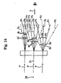
- a light beam P is incident from a point source 28 with a single color (short wavelength) through the diffraction grating plate 26, a zero-order light P0, first-order diffraction light P1, second-order diffraction light P2, ... are generated by the respective diffraction gratings as illustrated in Fig. 14.
- the zero-order light P0 is light that travels in a straight line through the diffraction grating plate 26, and the first-order diffraction light P1 is light whose direction is bent by first-order diffraction.
- the second-order diffraction light P2 is light whose direction is bent by first-order diffraction.
- diffraction angles ⁇ 1, ⁇ 2, ⁇ 3, ... of the first-order diffraction light P1 increase in order as the width of the diffraction grating groove 27 becomes narrower. Namely, a relationship, ⁇ 1 ⁇ ⁇ 2 ⁇ 3 ⁇ ,.., is established.
- diffraction angles ⁇ 1' ⁇ ⁇ 2' ⁇ ⁇ 3' ⁇ , ... of second-order diffraction light P2 increase in order as the width of diffraction grating groove 27 becomes narrower. Namely, a relationship, ⁇ 1' ⁇ ⁇ 2' ⁇ 3' ⁇ ..., is established.
- the light beam which is based on this zero-order diffraction light P0, corresponds to a spherical lens with degree of 0.
- the first-order diffraction light P1 of the upper side acts on a converging direction, so that the first-order diffraction light P1 functions as an imaginary convex lens with given degrees.
- first-order diffraction light P1 of the lower side acts on a diverging direction, so that the first order diffraction light P1 functions as an imaginary concave lens with given degrees.
- second-order diffraction light P1 of the upper aide the diffraction angles ⁇ 1' ⁇ ⁇ 2' ⁇ ⁇ 3' ⁇ , . increase two times as large as diffraction angles ⁇ 1 ⁇ ⁇ 2 ⁇ ⁇ 3 ⁇ , ...
- the second-order diffraction light P2 of the upper side functions as an imaginary convex lens that has degrees, which are two times as large as an imaginary convex lens with given degrees formed by the first-order diffraction light P1 of the upper side.
- the second-order diffraction light P2 of the lower side functions as an imaginary concave lens that has degrees, which are two times as large as an imaginary concave lens with given degrees formed by the first-order diffraction light P1 of the lower side.
- a plurality of images which are based on the plurality of point sources, are seen on a plane orthogonal to an optical axis O1 and at different distances in a direction of optical axis when seeing the point source 28 with a single color from a direction of an arrow X through the diffraction grating plate 26.
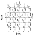
- a radiant image 28' of the point source 28 is seen on the optical axis 01 as illustrated in Fig. 15.
- a circle of confusion image 30 is seen. In this way, the diffraction grating plate 26 can be prepared
- the diameter of the circle of confusion image increases gradually from the optical axis O1.
- the circle of confusion image 80 exists on the front side in the direction of optical axis O1 and below the optical axis O1
- the circle of confusion image 30 exists on the other side of the optical direction and above the optical axis O1
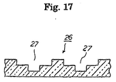
- the image of light source based on the zero-order diffraction light P0, that of light source based on the first-order diffraction light P1 and that of the second-order diffraction light P2 can have substantially the same intensity
- the light source (LED) 28 with a single color (short wavelength) is turned on in synchronization with the insertion of this diffraction grating plate 26. Then, a point target 31a is shown to the eyes E to be subjected to optometry through a pin hole 31a of a pin hole plate 31.
- this point target 31a is seen through the spherical lens 24, cylindrical lens 25, and diffraction grating plate 26 of the correction optical system 1, a plurality of target images are seen as if they were dispersed on a plane orthogonal to the optical axis 01 and shown simultaneously and symmetrically at a different distance in a direction of optical axis based on the real point target 31a as illustrated in Fig. 11.
- the point target 31a is seen as if it was positioned on the optical axis O1 as shown in Fig. 11. However, in a case where correction to the eyes E to be subjected to optometry is not ideally made, the point target 31a is seen as if it was placed at a position shifted from the optical axis 01 as shown in Fig. 18.
- the correction optical system 1 is adjusted such that the point target 31a is positioned on the optical axis 01, it is possible to carry out precise measurement of the astigmatic axis and astigmatic degree of the subject.
- a half mirror 32 is diagonally provided at the optical path of the correction optical system 1 so that a matrix sign table 33 including numerals and English letters in rows and columns is reflected in the half mirror 32, Then, the numerals and English letters of the matrix sign table 33 are shown to the eyes E to be subjected to optometry simultaneously so that the position of the point target 31a may be designated using the numerals and English letters.
- the joystick 33' is operated in a left direction (direction of an arrow H1). Resultantly, in synchronization with the operation of joystick 33' in a left direction, the degree of the cylindrical lens 25 to be inserted in the optical path of the correction optical system 1 is changed to -0. 25D.
- this operation is continued two times, the position of the point target 31a that can be clearly seen is moved from a position X1 to a position X2.
- the joystick 33' is operated in a direction of an arrow ZI to increase the degree of the spherical lens 24 to be inserted in the optical path of correction optical system 1 by 0. 25. Resultantly, the position of the point target 31a that can be clearly seen is moved from the position X2 to the optical axis O1.
- the amount of light is reduced by the diffraction function of the diffraction grating plate 26 as compared with the case in which no the diffraction grating plate 26 is inserted.
- the amount of light of the point source 28 may be increased by an amount corresponding to the reduction of the amount of light.
- a spherical degree 8 a cylindrical degree C and an axial angle A of the cylindrical axis 0 are roughly measured by the fogging measurement method.
- the diffraction grating plate 26 is inserted in the optical path of the correction optical system L
- the initial setting of the diffraction grating plate 26 to the optical path of the correction optical path 1 is designed such that a direction where one diffraction grating groove 27 extends is a vertical direction.
- an arrow Z1' shows a direction where one diffraction grating groove 27 extends
- the point source 28 with a single color is turned on. Then, the subject is caused to pay attention to the diagonal directions (45 degrees, 135 degrees) shown in Fig. 11.
- the degree of spherical lens is changed to adjust the point target 31a to be positioned on substantially the optical axis O1.
- precise measurement of the spherical degree S is carried out.
- the direction where the diffraction grating groove 27 of the diffraction grating plate 26 extends is roughly conformed to the direction where the cylindrical axis O extends.
- the cylindrical axis O is conformed to the direction Z1' where one diffraction grating groove 27 extends.
- the cylindrical degree C of the cylindrical lens 25 is changed and adjused by 0. 25D such that the length and clearness of the focal line images 29, which intersect at right angles, become symmetric with respect to the point target 31a. This carries out precise measurement of the cylindrical degree C.
- the diffraction grating plate 26 is inserted in the correction optical system 1, and the diffraction grating plate 26 is subjected to initial setting such that a direction where one diffraction grating groove 27 extends is a vertical direction. Then, the subject is caused to designate the position where the point target 31a can be seen using the joystick 33' in the initial setting state of the diffraction grating plate 26.
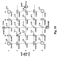
- a program that associates each position, which is seen as being discrete spatially, with power (which is used as concept including the cylindrical degree, convex and concave) of the cylindrical lens is installed onto the controller 24.
- the controller 24 has a program that computes the spherical degree S of the position where the point target can be seen, the cylindrical degree C and axial angle A of cylindrical axis O based on power of the cylindrical lens in the vertical direction, which corresponds to the position where the subject can see the point target 31a, and power of the cylindrical lens in the horizontal direction.
- the cross cylindrical lens is obtained when axes of two cylindrical lenses, each having a different sign and the same refractive power, are orthogonal to each other and combined. This can be expressed as a combination of a spherical lens and a cylindrical lens, and can be represented by the same equation as used in the toric lens.
- D ⁇ 0 ( S 1 + S 2 + ( C 1 + C 2 ) / 2 ) ⁇ C 1 / 2 ( cos 2 ⁇ cos 2 A 1 + sin 2 ⁇ sin 2 A 1 ) ⁇ C 2 / 2 ( cos 2 ⁇ cos 2 A 2 + sin 2 ⁇ sin 2 A 2 )
- the spherical degree S 0 , cylindrical degree C 0 and axial angle A 0 of cylindrical axis O of the composite refractive power D ⁇ 0 obtained by combining two toric lenses can be obtained from equations (g) to (i).
- the composite spherical degree So, cylindrical degree C 0 , and axial angle A 0 are calculated based on the spherical degree So, cylindrical degree Co and axial angle A 0 thus obtained and the spherical degree s, cylindrical degree C and axial angle A obtained by the approximate measurement.
- the spherical lens 24 and cylindrical lens 25, which correspond to the composite spherical degree So, cylindrical degree C 0 , and axial angle A 0 are set to the correction optical system 1.
- the axial angle A 0 of cylindrical lens 25 is also conformed to the composite axial angle A.
- the diffraction grating plate 26 is rotated about optical axis O1 by 45 degrees, and the subject is caused to designate the position where the point target 31a can be seen using the joystick SS' in a like manner.
- the spherical degree S, cylindrical degree C, and axial angle A of cylindrical axis O at the position where the point subject 31a can be seen are obtained by calculation. Then, the composite spherical degree S, cylindrical degree C and axial angle A of cylindrical axis O including the spherical degree S, cylindrical degree C, and axial angle A of cylindrical axis O obtained by this calculation and the spherical degree S, cylindrical degree C and axial angle of cylindrical axis O obtained by the approximate measurement are obtained.
- the diffraction grating plate 26 having only the diffraction grating groove 27, which extends longer horizontally. is used.
- a target 35 with three lines, which extend longer vertically, is used. This target 36 is illuminated by the light source 28 with a single color
- a plurality of target images 36 (five) can be seen.
- eyesight of the eyes E to be subjected to optometry is normal or subjected to correction ideally, that is, the astigmatic axis is adjusted and eyesight is normal, the length of the target image 36 on the optical axis O1 is seen in a state that the length is short and the lines in the vertical direction are uniformly seen clearly.
- the length of the target image 86 which is placed at the position shifted from the optical axis O1 is the shortest and the image can be clearly seen.
- Other target images 36 are seen blurrily.
- the spherical degree S, cylindrical degree C, and axial angle A of cylindrical axis O are obtained based on the above. Then, the composite spherical degree S, cylindrical degree C and axial angle A of cylindrical axis 0 are calculated based on the spherical degree S, cylindrical degree C, and axial angle A of cylindrical axis 0 obtained by the calculation and the spherical degree S, cylindrical degree C and axial angle of cylindrical axis 0 obtained by the approximate measurement.
- the spherical lens 24 and cylindrical lens 25, which correspond to the composite spherical degree S, cylindrical degree C, and axial angle A of cylindrical axis O, are set to the correction optical system 1. At this time, the axial angle A of cylindrical axis O of cylindrical lens 25 is also conformed to the composite axial angle A.
- the diffraction grating plate 26 is rotated about the optical axis O1 by 60 degrees, and the subject is caused to designate the position of target image 36, which is clearly seen as compared with the other target images 36, using the joystick 33', again.
- the composite spherical degree S, cylindrical degree C and axial angle A of cylindrical axis O are calculated. Then, the spherical lens and cylindrical lens, which correspond to the composite spherical degree S, cylindrical degree C, and axial angle A of cylindrical axis O are set to the correction optical system 1. Then, the diffraction grating plate 26 is rotated about the optical axis O1 by 60 degrees, again.
- the subject is caused to designate the position of target image 36, which is clearly seen as compared with the other target images 36, using the joystick 33', again.
- the present invention it is possible to precisely measure the spherical degree, angle of astigmatic degree, and astigmatic degree at one time. Moreover, it is possible to make the correction optical system of optometry compact.
Landscapes
- Life Sciences & Earth Sciences (AREA)
- Health & Medical Sciences (AREA)
- Surgery (AREA)
- Animal Behavior & Ethology (AREA)
- Ophthalmology & Optometry (AREA)
- Engineering & Computer Science (AREA)
- Biomedical Technology (AREA)
- Heart & Thoracic Surgery (AREA)
- Medical Informatics (AREA)
- Molecular Biology (AREA)
- Physics & Mathematics (AREA)
- Biophysics (AREA)
- General Health & Medical Sciences (AREA)
- Public Health (AREA)
- Veterinary Medicine (AREA)
- Eye Examination Apparatus (AREA)
- Diffracting Gratings Or Hologram Optical Elements (AREA)
- Lenses (AREA)
- Investigating Or Analysing Materials By Optical Means (AREA)
- Analysing Materials By The Use Of Radiation (AREA)
Abstract
Description
- The present invention relates to an optometry apparatus having an optical element by which targets can be seen as if they were dispersed in a plane orthogonal to an optical axis and presented simultaneously at a different distance or position in a direction of an optical axis through examined eyes to be subjected to optometry, and a diffraction grating plate as an optical element used in the same.
- Conventionally, an optometry apparatus makes a precise decision of an astigmatic axis of examined eyes to be subjected to optometry and of an astigmatic degree by use of a cross cylinder lens. As a method for deciding the astigmatic axis and astigmatic degree precisely using this cross cylinder lens, a cross cylinder method and an auto-cross cylinder method are known.
- In any method, firstly a spherical degree S, a cylindrical degree C, and an axial angle A of a cylindrical axis O are roughly measured, thereafter, the astigmatic axis of the examined eyes to be subjected to optometry and the astigmatic degree are precisely measured.
- For example, it is assumed that a spherical degree S (= -1.00D), a cylindrical degree C (= -0.50D) and an axial angle A of a cylindrical axis O (= 90 degrees) are set as a result of checking optical characteristic of one lens of eyeglasses in use currently by a lens meter.
- At the time of optometry, first of all, in order to remove accommodation power of eyes, as shown in Fig. 1, a
spherical lens 2 whose the spherical degree S is, for example, +3.00D, which is higher than a prospective degree, is set to an optometric window of a correctionoptical system 1 by fogging, and an eyesight-test chart is shown to a subject. In the case of the spherical degree S (= -1.00D), thespherical lens 2 with the spherical degree S (= +2.00D) is set to the optometric window, and the spherical degree S of thespherical lens 2 to be set to the optometric window is reduced by -0.25D so as to increase eyesight. - Then, an
astigmatic test chart 8 illustrated in Fig. 2 is shown to the subject at the stage which is one step before desirable eyesight, and the subject is asked how theastigmatic test chart 3 is seen. - In a case where the
astigmatic test chart 3 is blurredly seen uniformly, it can be judged that the subject is not a person with astigmatism. Here, it is assumed that the subject is a person with astigmatism. For example, if an answer "I can see the direction at 3 o'clock clearly" is received in response to a question "which direction at a clockwise can you see?", a cylindrical lens 4 is set to the optometric window of the correctionoptical system 1 and the cylindrical axis O is set in a direction orthogonal to a direction where clear vision can be obtained. Namely, the axial angle A of cylindrical axis O is set to 90 degrees. - After that, the cylindrical degree C of the cylindrical lens 4 to be set to the optometric window is increased 0.25 by 0.25, and the approximate measurement is completed when the degree of the cylindrical lens 4 reaches a value where the
astigmatic test chart 3 is clearly seen uniformly. - Additionally, in Fig. 1, reference numeral O1 denotes an optical axis of the correction
optical system 1. - Next, precise measurement of the cylindrical axis O and cylindrical degree C is performed.
- In case of the cross cylinder method, a cross
cylindrical lens 5 is inserted in the correctionoptical system 1. Thiscross cylinder lens 5 is structured such that the axis of(-) axial cylindrical lens is orthogonal to that of (+) axial cylindrical lens as shown in Fig. 1. - Then, an
intermediate axis 6 of the crosscylindrical lens 5 is allowed to conform to the cylindrical axis O of the cylindrical lens 4. Next, the crosscylindrical lens 5 is reversed using theintermediate axis 6 of the crosscylindrical lens 5 as a central axis. Then, the subject is allowed to look at apoint group chart 7 of Fig. 3. - Before and after the cross
cylindrical lens 5 is reversed at the time of showing thispoint group chart 7, the cylindrical lens 4 and crosscylindrical lens 5 are integrally rotated in a direction where a clear view is obtained by, for example 5 degrees to measure the axial angle A of the cylindrical lens 4 precisely. - Sequentially, as illustrated in Fig. 4, any one of (+) axis and (-) axis of the cross
cylindrical lens 5 is confirmed to the cylindrical axis O of the cylindrical lens 4. Fig. 4 shows a state in which (+) axis is confirmed, to thecylindrical axis 0. Then, the point group chart of Fig. 3 is shown to the subject. Next, thecross cylinder lens 5 is reversed using theintermediate axis 6 as a central axis and the (-) axis is conformed to the cylindrical axis O. Then, the point group chart of Fig. 3 is shown to the subject. After asking the subject a question about which way the chart can be clearly seen before or after the crosscylindrical lens 5 is reversed, the cylindrical degree C of thecylindrical lens 2 is set to a direction where a clear view can be obtained. - Thus, precise measurement of the subjects astigmatic axis and astigmatic degree is completed.
- In case of the auto-cross cylinder method, an auto cross
cylindrical lens 8 shown in Fig. 5 is used. This auto crosscylindrical lens 8 includes atriangular prism 9 and crosscylindrical lenses cylindrical lenses cylindrical lenses - The precise measurement of the astigmatic axis and astigmatic degree using this auto cross
cylindrical lens 8 is carried out, for example, as follows: - The approximate measurement of the spherical degree S, cylindrical degree C, and axial angle A of cylindrical axis O is the same as the case of the cross cylinder method.
- After the approximate measurement of the spherical degree S, cylindrical degree C, and axial angle A of
cylindrical axis 0, anintermediate axis 12 of the auto crosscylindrical lens 8 is confirmed to the cylindrical axis O of the cylindrical lens 4 as shown in Fig. 6. Consequently, the plus axis (+) of the upper-sidecross cylinder lens 10 is set to a direction at 45 degrees with respect to thecylindrical axis 0 and the minus axis (-) thereof is set to a direction at 135 degrees. Moreover, the minus axis (-) of the lower-sidecross cylinder lens 11 is set to a direction at 45 degrees with respect to the cylindrical axis O and the plus axis (+) thereof is set to a direction at 135 degrees. - Then, the
point group chart 7 of Fig. 3 is similarly shown to the subject so that the subject is allowed to perform comparison between thepoint group chart 7 seen through the upper-sidecross cylinder lens 10 and thepoint group chart 7 seen through the lower-sidecross cylinder lens 11 simultaneously to check which chart can be clearly seen. Then, the cylindrical lens 4 is rotated integrally with theauto cross cylinder 8 in the direction where a good view can be obtained. Thus, the axial angle A of the cylindrical axis O is decided. - After that, the
cross cylinder lenses cross cylinder lens 10 is conformed to the cylindrical axis O and the minus (-) of thecross cylinder lens 11 is conformed to the cylindrical axis O as illustrated in Fig. 7. After performing comparison between thepoint group chart 7 seen through thecross cylinder lens 10 and thepoint group chart 7 seen through thecross cylinder lens 11 simultaneously to check which chart can be clearly seen, the cylindrical degree C of the cylindrical lens 4, which is inserted in the optical path of the correctionoptical system 1, is changed to the direction where the good view can be obtained. - Thus, precise measurement of the axial angle A of the cylindrical axis and cylindrical degree C is completed.
- Next, precise measurement of the spherical degree S is performed.
- In this precise measurement of the spherical degree S, a so-called red and
green chart 13 is shown as illustrated in Fig. 8. In a case where a target seen through a red filter can be seen well, since such a situation is considered that correction is lack, the spherical degree S of thespherical lens 2 is increased. In a case where a target seen through a green filter can be seen well, since such a situation is considered that correction is excessive, the spherical degree S of thespherical lens 2 is decreased. - Thus, the precise measurement of the spherical degree S is completed.
- However, in the optometry apparatus by the cross cylinder method, since an operation to reverse the
cross cylinder lens 5 is carried out at the target comparing time, the targets cannot be compared simultaneously. Accordingly, since judgment is made by separated observation in which judgment is made with a time difference, it is difficult for the subject to judge which the target can be seen well. - Moreover, there is a disadvantage in which the spherical degree S, cylindrical degree C and the axial angle A of the cylindrical axis cannot be measured simultaneously.
- Still moreover, many subjects answer that the subject can see the
respective points 7a more easily whoseprofile lines 7b are clearly seen in the direction of astigmatic axis as illustrated in a partially enlarged view of Fig. 9, as compared with therespective points 7a of thepoint group chart 7 of Fig. 3 which are blurredly seen uniformly. - On the other hand, in the optometry apparatus by the auto cross cylinder method, since a contrastive observation that performs comparison between the targets simultaneously is performed, the subject can easily judge which the target can be seen well as compared with the case of using the cross cylinder method.
- However, similarly to the cross cylinder method, this auto cross cylinder method has a disadvantage in which the spherical degree S, cylindrical degree C and axial angle A of cylindrical axis cannot be measured simultaneously. Moreover, similar to the cross cylinder method, many subjects answer that the subject can see more easily the
respective points 7a whoseprofile lines 7b are clearly seen in the direction of astigmatic axis as illustrated in a partially enlarged view of Fig. 9, as compared with therespective points 7a ofpoint group chart 7 of Fig. 3 which are blurredly seen uniformly. - Still moreover, though the contrastive conversation that contrasts the targets simultaneously and compares them can be carried out, the number of targets to be compared is only two and it is difficult to judge which is clearly seen.
- In addition, in a case where the subject is extremely farsighted or nearsighted, a difference occurs in the way to see the targets simultaneously presented due to influence of aberration of the correction
optical system 1 unless the eyes to be subjected to optometry are set to a correct position. - In the case of precise measurement of spherical degree using the red and
green test chart 13, there are many answers indicating that the target with a favorite color is seen well - US-A-5914772 Discloses a device for testing eyes which comprises an autorefractor, an autolensometer, an autophoropter, a display device, an input device, a printing device, and a computer interfacing with each of the components. This testing device can be used for performing a method comprising the steps of obtaining autorefractor, corrected autorefractor, and autolenscmeter results; calculating sphere; performing a Red-Green test; calculating cylinder and axis; determining minimum cylinder power; determining final sphere; and recording all data.
- The present invention has been made with consideration given to the aforementioned problems and it is an object of the present invention is to provide an optometry apparatus that can measure a spherical degree S, a cylindrical degree C and an axial angle A of a cylindrical axis O at one time, so that targets are seen as if they were dispersed in a plane orthogonal to an optical axis and shown simultaneously at a different distance or position in a direction of the optical axis.
- This object according to the invention is solved by an optometry apparatus comprising the features of
claim 1. Preferred embodiments of this apparatus are defined in the subclaims. - An optometry apparatus according to the present invention comprises a spherical lens, a cylindrical lens and optical element constructed so that targets appear to examined eyes to be subjected to optometry as if the targets were dispersed on a plane orthogonal to an optical axis and shown simultaneously at a different distance or position in a direction of the optical axis, wherein the optical element is formed of a diffraction grating plate where periodicity of a diffraction grating changes.
- In the optometry apparatus according to another preferred embodiment the diffraction grating plate is capable of going/coming to/from an optical path of the correction optical system.
- In the optometry apparatus according to further preferred embodiment, when the diffraction grating plate is inserted in an optical axis of the correction optical system, the targets are shown by a.point light source with a single color.
- In the optometry apparatus according to a still further preferred embodiment, when the diffraction grating plate is inserted in the optical axis of said correction optical system, a light quantity of the point light source with a single color is increased.
- In the optometry apparatus according to a still further preferred embodiment, a subject himself/herself designates a target, which seems to be the best among the plurality of targets shown simultaneously and adjusts said correction optical system.
- In the optometry apparatus according to a still further preferred embodiment, matrix signs, which can designate the plurality of targets in the form of matrix, are simultaneously shown to the eyes to be subjected to optometry such that the subject himself/herself is caused to designate the target, which seems to be the best among the plurality of targets shown simultaneously.
- In the optometry apparatus according to a still further preferred embodiment, the matrix sings are shown in an optical path of the correction optical system through a half mirror, or the matrix signs are shown with a wavelength by which no diffraction power is generated.
- In the optometry apparatus according to a still further preferred embodiment, the subject himself/herself adjusts the correction optical system using a joystick such an target, which seems to be the best among the plurality of targets shown simultaneously, is positioned on an optical axis of the correction optical system.
- In the optometry apparatus according to s still further preferred embodiment, the diffraction grating plate is rotated together with the cylindrical lens, so that a spherical degree, a cylindrical degree and an axial angle of a cylindrical axis are precisely measured.
- In the optometry apparatus according to a still further embodiment, the diffraction grating plate is rotated by 45 degrees from an initial setting state to determine a spherical degree, a cylindrical degree and an axial angle of a cylindrical axis by calculation. A spherical degree, a cylindrical degree and an axial angle of a cylindrical axis are determined by the calculation are synthesized with a cylindrical degree and an axial angle of a cylindrical axis determined by approximate measurement. The spherical degree, the cylindrical degree and the axial angle of cylindrical axis are precisely measured by the synthesized spherical degree, cylindrical degree, and axial angel of cylindrical axis obtained by this calculation.
- In the optometry apparatus according to a still further preferred embodiment, the diffraction grating plate is rotated by 60 degrees two times from am initial setting state to determine a spherical degree, a cylindrical degree and an axial angle of a cylindrical axis by calculation. A spherical degree, a cylindrical degree and an axis angle of a cylindrical axis are determined by calculation where the spherical degree, the cylindrical degree and the axial angle of cylindrical axis determined by the calculation are synthesized with a spherical degree, a cylindrical degree and an axial angle of a cylindrical axis determined by approximate measurement. The spherical degree, the cylindrical degree and the axial angle of cylindrical axis are precisely measured by the synthesized spherical degree, cylindrical degree, and axial angle of cylindrical axis determined by this calculation.
- In the optometry apparatus according to a still further preferred embodiment, a pin hole plate having a point target is provided between the point light source with a single color and the diffraction grating plate.
-
- Fig. 1 is an explanatory view illustrating an example of precise measurement of an axial angle of a cylindrical axis of a cylindrical lens by a cross cylinder method;
- Fig. 2 is a view illustrating one example of an astigmatic chart;
- Fig. 3 is a view illustrating one example of point group targets;
- Fig. 4 is a view illustrating one example of precise measurement of a cylindrical degree of a cylindrical lens by the cross cylinder method;
- Fig. 5 is a side view showing one example of an auto cross cylinder;
- Fig. 6 is an explanatory view illustrating one example of precise measurement of an axial angle of a cylindrical axis of a cylindrical lens by an auto cross cylinder method;
- Fig. 7 is an explanatory view illustrating an example of precise measurement of a cylindrical degree of a cylindrical lens by an auto cross cylinder method;
- Fig. 8 is a view illustrating one example of a red and green chart;
- Fig. 9 is an explanatory view illustrating one way how a point group of Fig. 3 is seen;
- Fig. 10 is an outline view showing a general outline of an optometry apparatus according to the present invention;
- Fig. 11 is an explanatory view showing a general outline of a correction optical system according to the present invention;
- Fig. 12 is a schematic view to conceptually explain a periodic pattern of diffraction grating grooves of a diffraction grating plate shown in Fig. 11;
- Fig. 13 is a cross-sectional view taken along line Z2-Z2 indicated by arrows of Fig. 12;
- Fig. 14 is an explanatory view to explain the function of the diffraction grating plate shown in Fig. 12;
- Fig. 15 is an explanatory view illustrating the way how the target is seen when a point source with a single color is seen via the diffraction grating plate shown in Fig. 12;
- Fig. 16 is an explanatory view illustrating that a focal line image as a target is shown three-dimensionally when a point source with a single color is seen via the diffraction grating plate shown in Fig. 12;
- Fig. 17 is a partially enlarged cross-sectional view of diffraction grating grooves to explain a state in which the diffraction grating grooves are formed stepwise to make luminance of each target image constant;
- Fig. 18 is an explanatory view to explain a state in which a position of a point target is seen as if it were shifted from the optical axis of correction optical system;
- Fig. 19 is a schematic view illustrating one example of the correction optical system to which such ingenuity that a matrix sign table is made to correspond to a target image to be shown to a subject is made;
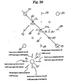
- Fig. 20 is an explanatory view illustrating a state in which a subject himself/herself operates a joystick to adjust the position of target image;
- Fig. 21 is a schematic view conceptually showing other example of a periodic pattern of the diffraction grating grooves of the diffraction grating plate;
- Fig. 22 is an explanatory view illustrating other example of a target to be shown via the diffraction grating plate of Fig. 21;
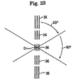
- Fig. 23 is an explanatory view illustrating one example of the way how the target is seen when the target of Fig. 22 is seen via the diffraction grating plate of Fig. 21
- Fig. 10 is an explanatory view showing a schematic structure of an optometry apparatus according to the present invention.
- In Fig. 10,
reference numeral 20 is an , 21 is a subject, 22 is a target presenting apparatus, 23 is a Phoroptor, and 24 is a controller. - The
Phoroptor 23 is provided with aspherical lens 24 having a different spherical degree S, acylindrical lens 25 having a different cylindrical degree C and adiffraction grating plate 26 as an optical element as shown in Fig. 11. Thesespherical lens 24,cylindrical lens 25 anddiffraction grating plate 26 are set to an optometric window of thePhoroptor 23 as required. - Fig. 11 shows a state in which approximate measurement of a spherical degree S, a cylindrical degree C and an axial angle A with respect to examined eyes E subjected to optometry is finished and the
spherical lens 24 and thecylindrical lens 25, which serve as correctionoptical system 1, are inserted in the optometry window. Here, it is assumed that the axial angle A of the cylindrical axis O of thecylindrical lens 25 is set to 90 degrees similar to the conventional case. - The
diffraction grating plate 26 is used to carry out precise measurement of an astigmatic axis of the eyes to be subjected to optometry, an astigmatic degree, and a spherical degree. Thediffraction grating plate 26 is inserted in the optical path of the correctionoptical system 1 in place of the conventional cross cylindrical lens, and is capable of going/curring to/from the optical path of the correctionoptical system 1. - As schematically shown in Figs. 12 and 18, in the
diffraction grating plate 26,diffraction grating grooves 27 whose periodicity (pitch) continuously changes are formed vertically and horizontally. When a light beam P is incident from apoint source 28 with a single color (short wavelength) through thediffraction grating plate 26, a zero-order light P0, first-order diffraction light P1, second-order diffraction light P2, ... are generated by the respective diffraction gratings as illustrated in Fig. 14. - The zero-order light P0 is light that travels in a straight line through the
diffraction grating plate 26, and the first-order diffraction light P1 is light whose direction is bent by first-order diffraction. The second-order diffraction light P2 is light whose direction is bent by first-order diffraction. However, diffraction angles θ1, θ2, θ3, ... of the first-order diffraction light P1 increase in order as the width of the diffractiongrating groove 27 becomes narrower. Namely, a relationship,θ 1 <θ 2 <θ 3 < ,.., is established. Similarly, diffraction angles θ 1'< θ 2' < θ 3' <, ... of second-order diffraction light P2 increase in order as the width of diffractiongrating groove 27 becomes narrower. Namely, a relationship, θ 1' < θ2'<θ3'<..., is established. - Accordingly, if attention is paid to only zero-order diffraction light P0, the light beam, which is based on this zero-order diffraction light P0, corresponds to a spherical lens with degree of 0. If attention is paid to only the first-order diffraction light P1 of the upper side, the first-order diffraction light P1 of the upper side acts on a converging direction, so that the first-order diffraction light P1 functions as an imaginary convex lens with given degrees. Moreover, if attention is paid to only the first-order diffraction light P1 of the lower side, first-order diffraction light P1 of the lower side acts on a diverging direction, so that the first order diffraction light P1 functions as an imaginary concave lens with given degrees. Still moreover, if attention is paid to only second-order diffraction light P1 of the upper aide, the diffraction angles θ1'< θ 2' < θ 3'<, ..... increase two times as large as diffraction angles θ1 <
θ 2 <θ 3 <, ... of first-order diffraction light P2 of the upper side, so that the second-order diffraction light P2 of the upper side functions as an imaginary convex lens that has degrees, which are two times as large as an imaginary convex lens with given degrees formed by the first-order diffraction light P1 of the upper side. Similarly, the second-order diffraction light P2 of the lower side functions as an imaginary concave lens that has degrees, which are two times as large as an imaginary concave lens with given degrees formed by the first-order diffraction light P1 of the lower side. - According a plurality of images, which are based on the plurality of point sources, are seen on a plane orthogonal to an optical axis O1 and at different distances in a direction of optical axis when seeing the
point source 28 with a single color from a direction of an arrow X through thediffraction grating plate 26. - By devising ingenuity to the
diffraction grating grooves 27 of thediffraction grating plate 26, it is possible to prepare an optical element that has a function exhibited by combing a concave cylindrical lens whose degree differs 0. 25D by 0.25D and whose cylindrical axis O is orthogonal thereto with a convex cylindrical lens. - Specifically, when a person, who has good eyesight or ideally corrected eyesight, sees the
point source 28, a radiant image 28' of thepoint source 28 is seen on theoptical axis 01 as illustrated in Fig. 15. In a vertical upper direction, afocal line image 29, which corresponds to a convex cylindrical lens with cylindrical degree C and axial angle A (=180 degrees) of the cylindrical axis O, is seen. In a vertical lower direction, afocal line image 29, which corresponds to a concave cylindrical lens with the cylindrical degree C and the axial angle A(= 180 degree) of the cylindrical axis O, is seen. At a horizontally right side, afocal line image 29, which corresponds to a convex cylindrical lens with the axial angle A (= 90 degrees) of the cylindrical axis O, is seen. At a horizontally left side, afocal line image 29, which corresponds to a concave cylindrical lens with the cylindrical degree C and axial angle A (=90 degrees) of the cylindrical axis O, is seen. Then, in diagonal direction between the vertical and horizontal directions, a circle ofconfusion image 30 is seen. In this way, thediffraction grating plate 26 can be prepared - In view of the diagonal direction, the diameter of the circle of confusion image increases gradually from the optical axis O1. In accordance with the degree of the blur of image, if the circle of confusion image 80 exists on the front side in the direction of optical axis O1 and below the optical axis O1, the circle of
confusion image 30 exists on the other side of the optical direction and above the optical axis O1 - Namely, if only the positions where the focal line images are formed is shown three-dimensionally, they are as illustrated in Fig. 16.
- Additionally, by modifying the cross-sectional shape of the diffraction grating groove of
diffraction grating plate 26 to a shape as illustrated in an enlarged view of Fig. 17, the image of light source based on the zero-order diffraction light P0, that of light source based on the first-order diffraction light P1 and that of the second-order diffraction light P2 can have substantially the same intensity - When such
diffraction grating plate 26 is inserted in the optical path of a correctionoptical system 1 as illustrated in Fig. 11, the light source (LED) 28 with a single color (short wavelength) is turned on in synchronization with the insertion of thisdiffraction grating plate 26. Then, a point target 31a is shown to the eyes E to be subjected to optometry through a pin hole 31a of apin hole plate 31. - If this point target 31a is seen through the
spherical lens 24,cylindrical lens 25, anddiffraction grating plate 26 of the correctionoptical system 1, a plurality of target images are seen as if they were dispersed on a plane orthogonal to theoptical axis 01 and shown simultaneously and symmetrically at a different distance in a direction of optical axis based on the real point target 31a as illustrated in Fig. 11. - In a case where correction to the examined eyes E to be subjected to optometry is ideally made, the point target 31a is seen as if it was positioned on the optical axis O1 as shown in Fig. 11. However, in a case where correction to the eyes E to be subjected to optometry is not ideally made, the point target 31a is seen as if it was placed at a position shifted from the
optical axis 01 as shown in Fig. 18. - Accordingly, if the correction
optical system 1 is adjusted such that the point target 31a is positioned on theoptical axis 01, it is possible to carry out precise measurement of the astigmatic axis and astigmatic degree of the subject. - In connection with ingenuity to decide the position of the point target 31a, for example, a
half mirror 32 is diagonally provided at the optical path of the correctionoptical system 1 so that a matrix sign table 33 including numerals and English letters in rows and columns is reflected in thehalf mirror 32, Then, the numerals and English letters of the matrix sign table 33 are shown to the eyes E to be subjected to optometry simultaneously so that the position of the point target 31a may be designated using the numerals and English letters. - Additionally, it is possible to adopt a structure in which without providing the
half mirror 32, the matrix sign table 33 is directly displayed in the optical path of the correctionoptical system 1 with a wavelength by which no diffraction power is produced - Moreover, the horizontal right side corresponds to a convex cylindrical lens with the axial angle A (= 90 degrees) of the cylindrical axis O and the cylindrical degrees (C = 0. 25 and 0.5). The horizontal left side corresponds to the concave cylindrical lens with the axial angle (= 90 degrees) A of the
cylindrical axis 0 and the cylindrical degrees C (= -0, 26 and -0.5). The vertical upper side corresponds to the convex cylindrical lens with the axial angle A (= 180 degrees) of the cylindrical axis O and the cylindrical degrees C (= 0. 25 and 0.5). The vertical lower side corresponds to the concave cylindrical lens with the axial angle A (=180 degrees) of the cylindrical axis O and the cylindrical degrees C (= -0. 25 and -0.5). The diagonal direction corresponds to the change in the degree of the spherical lens. Accordingly, as shown in Fig. 10, such a structure may be adopted that the subject himself or herself operates the joystick 33' to associate the movement of joystick 33' in a slanting direction with the change in the spherical degree S and to see the point target 31a as if it was positioned on the optical axis O1 in accordance with an exchange between convex and concave cylindrical lenses and a change in the cylindrical degree C as leaving the axial angle A of thecylindrical axis 0 = 90 degrees unchanged so as to correspond to in accordance with the horizontal movement of a joystick 33' ofcontroller 24, as well as in accordance with an exchange between convex and concave cylindrical lenses and a change in the cylindrical degree C as leaving the axial angle A of thecylindrical axis 0 = 180 degrees unchanged so as to correspond to the vertical movement of joystick 33'. - For example, when the point target 31a is seen at a position of -0. 25D vertically and a position of +0. 25D horizontally as illustrated in Fig. 20, the joystick 33' is operated in a left direction (direction of an arrow H1). Resultantly, in synchronization with the operation of joystick 33' in a left direction, the degree of the
cylindrical lens 25 to be inserted in the optical path of the correctionoptical system 1 is changed to -0. 25D. When this operation is continued two times, the position of the point target 31a that can be clearly seen is moved from a position X1 to a position X2. - After that, the joystick 33' is operated in a direction of an arrow ZI to increase the degree of the
spherical lens 24 to be inserted in the optical path of correctionoptical system 1 by 0. 25. Resultantly, the position of the point target 31a that can be clearly seen is moved from the position X2 to the optical axis O1. - This makes it possible for the subject himself or herself to carry out precise measurement of the astigmatic axis and astigmatic degree.
- In addition, when the
diffraction grating plate 26 is inserted in the optical path of the correctionoptical system 1, the amount of light is reduced by the diffraction function of thediffraction grating plate 26 as compared with the case in which no thediffraction grating plate 26 is inserted. In this case, the amount of light of thepoint source 28 may be increased by an amount corresponding to the reduction of the amount of light. - In connection with precise measurement of the astigmatic axis and astigmatic degree using this
diffraction grating plate 26, the following will specifically explain three embodiments. - First, similar to the conventional case, a
spherical degree 8, a cylindrical degree C and an axial angle A of thecylindrical axis 0 are roughly measured by the fogging measurement method. - Next, the
diffraction grating plate 26 is inserted in the optical path of the correction optical system L The initial setting of thediffraction grating plate 26 to the optical path of the correctionoptical path 1 is designed such that a direction where onediffraction grating groove 27 extends is a vertical direction. In Fig. 11, an arrow Z1' shows a direction where onediffraction grating groove 27 extends, - In association with the insertion of the
diffraction grating plate 26 to the optical path, thepoint source 28 with a single color is turned on. Then, the subject is caused to pay attention to the diagonal directions (45 degrees, 135 degrees) shown in Fig. 11. - After this, the degree of spherical lens is changed to adjust the point target 31a to be positioned on substantially the optical axis O1. Thus, precise measurement of the spherical degree S is carried out. Next, the direction where the diffraction
grating groove 27 of thediffraction grating plate 26 extends is roughly conformed to the direction where the cylindrical axis O extends. Here, the cylindrical axis O is conformed to the direction Z1' where onediffraction grating groove 27 extends. - Then, the
diffraction grating plate 26 is slightly rotated with thecylindrical lens 25. Namely, thecylindrical lens 25 anddiffraction grating plate 26 are slightly rotated +0.5 and -0. 5 degrees about theoptical axis 01 with respect to the axial angle A (= 90 degrees) of the cylindrical axis O roughly obtained. Thus, precise measurement of the axial angle A of thecylindrical axis 0 is carried out. - Next, the cylindrical degree C of the
cylindrical lens 25 is changed and adjused by 0. 25D such that the length and clearness of thefocal line images 29, which intersect at right angles, become symmetric with respect to the point target 31a. This carries out precise measurement of the cylindrical degree C. - The approximate measurement of a spherical degree S, a cylindrical degree C and an axial angle A of the cylindrical axis is the same that of
Embodiment 1. - The
diffraction grating plate 26 is inserted in the correctionoptical system 1, and thediffraction grating plate 26 is subjected to initial setting such that a direction where onediffraction grating groove 27 extends is a vertical direction. Then, the subject is caused to designate the position where the point target 31a can be seen using the joystick 33' in the initial setting state of thediffraction grating plate 26. - It is possible to designate the position using the matrix sign table 33 in place of the joystick 33'.
- A program that associates each position, which is seen as being discrete spatially, with power (which is used as concept including the cylindrical degree, convex and concave) of the cylindrical lens is installed onto the
controller 24. - The
controller 24 has a program that computes the spherical degree S of the position where the point target can be seen, the cylindrical degree C and axial angle A of cylindrical axis O based on power of the cylindrical lens in the vertical direction, which corresponds to the position where the subject can see the point target 31a, and power of the cylindrical lens in the horizontal direction. - In connection with the spherical degree S, cylindrical degree C and axial angle A, for example, the following equations are used.
- The following will explain general equations of a cross cylindrical lens and a toric lens.
- The cross cylindrical lens is obtained when axes of two cylindrical lenses, each having a different sign and the same refractive power, are orthogonal to each other and combined. This can be expressed as a combination of a spherical lens and a cylindrical lens, and can be represented by the same equation as used in the toric lens.
- Now, it is assumed that a spherical degree of the toric lens is S, a cylindrical degree is C, and an axial angle is A Refractive power D θ in a longitudinal direction at position with an angle θ from the cylindrical axis O can be expressed as follows:

- This general equation can be deformed as follows:

- The composite equation of two toric lenses is obtained as follows:
- In connection with the toric lens with composite refractive power D θ0 obtained by combining two taric lenses each having refractive
power D θ 1 and D θ. 2, if each spherical degree, cylindrical degree and axial angle are D θ1 (S1, C1, A1), D θ, 2(S2, C2, A2), and D θ0 (S0, C0, A0) respectively, each toric lens can be expressed as follows from equation (a):
- Werein, since D θ0 is the sum of D θ1 and D θ2, the following equation is given:

- If the above equation is deformed, the following equation is given:

- From the correspondence between equations (b) and (c), the following equations can be obtained:


- Equation (d) can be written as follows:

- If both sides of equations (e) and (f) are squared to find the sum, the following equation is obtained:

- From the product of (e) and (f), the following equation is given:

- Here, the value of A0 follows the following relationahip when C18in2A1 + Casin2A2= Y and C1cos2A1+C2cos2A2 = X.
- WhenX = 0 AND Y = 0, A0 = 0°
- When X = 0 AND Y > 0, A0 = 45°
- When X = 0 AND Y < 0, A0 = 135°
- When Y = 0 AND X > 0, A0 = 0°
- When Y = 0 AND X < 0, A0 = 90°
- Wheta X > 0 AND Y > 0, A0 = A°
- When X < 0 AND Y > 0, A0 = A° + 90°
- When X < 0 AND Y < 0, A0 = A° + 90°
- When X>0 AND Y<0, A0=A°+180°
- Thus, the spherical degree S0, cylindrical degree C0 and axial angle A0 of cylindrical axis O of the composite refractive power D θ0 obtained by combining two toric lenses can be obtained from equations (g) to (i).
- Sequentially, the composite spherical degree So, cylindrical degree C0, and axial angle A0 are calculated based on the spherical degree So, cylindrical degree Co and axial angle A0 thus obtained and the spherical degree s, cylindrical degree C and axial angle A obtained by the approximate measurement.
- Then, the
spherical lens 24 andcylindrical lens 25, which correspond to the composite spherical degree So, cylindrical degree C0, and axial angle A0, are set to the correctionoptical system 1. At this time, the axial angle A0 ofcylindrical lens 25 is also conformed to the composite axial angle A. - Then, the
diffraction grating plate 26 is rotated about optical axis O1 by 45 degrees, and the subject is caused to designate the position where the point target 31a can be seen using the joystick SS' in a like manner. - At the position where this
diffraction grating plate 26 is rotated by 45 degrees, the spherical degree S, cylindrical degree C, and axial angle A of cylindrical axis O at the position where the point subject 31a can be seen are obtained by calculation. Then, the composite spherical degree S, cylindrical degree C and axial angle A of cylindrical axis O including the spherical degree S, cylindrical degree C, and axial angle A of cylindrical axis O obtained by this calculation and the spherical degree S, cylindrical degree C and axial angle of cylindrical axis O obtained by the approximate measurement are obtained. - The composite spherical degree S, cylindrical degree C and axial angle A of cylindrical axis O are obtained, so that precise measurement is ended.
- In the case of
Embodiment 3, as illustrated in Fig. 21, thediffraction grating plate 26 having only the diffractiongrating groove 27, which extends longer horizontally. is used. Moreover, as illustrated in Fig. 22, atarget 35 with three lines, which extend longer vertically, is used. Thistarget 36 is illuminated by thelight source 28 with a single color - When the
target 35 is seen through thediffraction grating plate 26 shown in Fig. 21, a plurality of target images 36 (five) can be seen. At this time, if eyesight of the eyes E to be subjected to optometry is normal or subjected to correction ideally, that is, the astigmatic axis is adjusted and eyesight is normal, the length of thetarget image 36 on the optical axis O1 is seen in a state that the length is short and the lines in the vertical direction are uniformly seen clearly. - When the degree of eyes to be subjected to optometry is not adjusted, the length of the target image 86, which is placed at the position shifted from the optical axis O1, is the shortest and the image can be clearly seen.
Other target images 36 are seen blurrily. - Here, in the initial state, the direction where the diffraction
grating groove 27 ofdiffraction grating plate 26 is set to the horizontal direction, the position oftarget image 36, which is clearly seen as compared with theother target images 36, is designated using the joystick 33'. - Similar to
Embodiment 2, the spherical degree S, cylindrical degree C, and axial angle A of cylindrical axis O are obtained based on the above. Then, the composite spherical degree S, cylindrical degree C and axial angle A ofcylindrical axis 0 are calculated based on the spherical degree S, cylindrical degree C, and axial angle A ofcylindrical axis 0 obtained by the calculation and the spherical degree S, cylindrical degree C and axial angle ofcylindrical axis 0 obtained by the approximate measurement. - The
spherical lens 24 andcylindrical lens 25, which correspond to the composite spherical degree S, cylindrical degree C, and axial angle A of cylindrical axis O, are set to the correctionoptical system 1. At this time, the axial angle A of cylindrical axis O ofcylindrical lens 25 is also conformed to the composite axial angle A. - Then, the
diffraction grating plate 26 is rotated about the optical axis O1 by 60 degrees, and the subject is caused to designate the position oftarget image 36, which is clearly seen as compared with theother target images 36, using the joystick 33', again. - By the similar calculation, the composite spherical degree S, cylindrical degree C and axial angle A of cylindrical axis O are calculated. Then, the spherical lens and cylindrical lens, which correspond to the composite spherical degree S, cylindrical degree C, and axial angle A of cylindrical axis O are set to the correction
optical system 1. Then, thediffraction grating plate 26 is rotated about the optical axis O1 by 60 degrees, again. - Then, the subject is caused to designate the position of
target image 36, which is clearly seen as compared with theother target images 36, using the joystick 33', again. - By the similar calculation, the composite spherical degree S, cylindrical degree C and axial angle A of cylindrical axis O are calculated, again.
- Thus, measurement in a longitudinal direction is performed to the eyes E to be subjected to optometry, and precise measurement of astigmatic degree and astigmatic axis of the eyes E to be subjected to optometry is ended.
- According to the present invention, it is possible to precisely measure the spherical degree, angle of astigmatic degree, and astigmatic degree at one time. Moreover, it is possible to make the correction optical system of optometry compact.
Claims (13)
- An optometry apparatus in which a target appears to examined. eyes (E) through a point light source (28) with a single color and a correction optical system (1) for correcting the examined eyes (E), characterized in that
said correction optical system (1) comprises a spherical lens (24), a cylindrical lens (25) and an optical element constructed so that targets appear to the examined eyes (E) to be subjected to optometry as if the targets were dispersed on a plane orthogonal to an optical axis (O1) and shown simultaneously at a different distance or position in a direction of the optical axis (O1), and
said optical element is formed of a diffraction grating plate (26) where periodicity of a diffraction grating changes. - The optometry apparatus according to claim 1, characterized in that said diffraction grating plate (26) is capable of going/coming to/from an optical path of said correction optical system (1).
- The optometry apparatus according to claim 1, characterized in that, when said diffraction grating plate (26) is inserted in an optical axis (01) of said correction optical system (1), the targets are shown by said point light source (28) with a single color.
- The optometry apparatus according to claim 3, characterized in that, when said diffraction grating plate (26) is inserted in the optical axis (01) of said correction optical system (1), a light quantity of the point light source (28) with a single color is increased.
- The optometry apparatus according to claim 1, characterized in that a subject himself/herself designates a target, which seems to be the best among the plurality of targets shown simultaneously and adjusts said correction optical system (1).
- The optometry apparatus according to claim 5, characterized in that matrix signs (33), which can designate said plurality of targets in the form of matrix, are simultaneously shown to the eyes to be subjected to optometry such that the subject himself/herself is caused to designate the target, which seems to be the best among the plurality of targets shown simultaneously.
- The optometry apparatus according to claim 6, characterized in that said matrix signs (33) are shown in an optical path of said correction optical system (1) through a half mirror (32).
- The optometry apparatus according to claim 6, characterized in that said matrix signs (33) are shown with a wavelength by which no diffraction power is generated.
- The optometry apparatus according to claim 1, characterized in that the subject himself/herself adjusts said correction optical system (1) using a joystick (33') such an target, which seems to be the best among the plurality of targets shown simultaneously, is positioned on an optical axis (θ1) of said correction optical system (1).
- The optometry apparatus according to claim 1, characterized in that said diffraction grating plate (26) is rotated together with the cylindrical lens (25), so that a spherical degree, a cylindrical degree and an axial angle of a cylindrical axis are precisely measured.
- The optometry apparatus according to claim 1, characterized in that said diffraction grating plate (26) is rotated by 45 degrees from an initial setting state, a spherical degree, a cylindrical degree and an axial angle of a cylindrical axis are determined by calculation, and a spherical degree, a cylindrical degree and an axial angle of a cylindrical axis are determined by calculation where the spherical degree, the cylindrical degree and the axial angle of cylindrical axis determined by the calculation are synthesized with a cylindrical degree and an axial angle of a cylindrical axis determined by approximate measurement, and the spherical degree, the cylindrical degree and the axial angle of cylindrical axis are precisely measured by the synthesized spherical degree, cylindrical degree and axial angle of cylindrical axis obtained by this calculation.
- The optometry apparatus according to claim 1, characterized in that said diffraction grating plate (26) is rotated by 60 degrees two times from an initial setting state, a spherical degree, a cylindrical degree and an axial angle of a cylindrical axis are determined by calculation, and a spherical degree, a cylindrical degree and an axial angle of a cylindrical axis are determined by calculation where the spherical degree, the cylindrical degree and the axis angle of cylindrical axis determined by the calculation are synthesized with a spherical degree, a cylindrical degree and an axial angle of a cylindrical axis determined by approximate measurement, and the spherical degree, the cylindrical degree and the axial angle of cylindrical axis are precisely measured by the synthesized spherical degree, cylindrical degree, and axial angle of cylindrical axis determined by this calculation.
- The optometry apparatus according to claim 1, characterized in that a pin hole plate (31) having a point target (31a) is provided between said point light source (28) with a single color and said diffraction grating plate (26).
Applications Claiming Priority (2)
| Application Number | Priority Date | Filing Date | Title |
|---|---|---|---|
| JP2001123245 | 2001-04-20 | ||
| JP2001123245A JP2002315724A (en) | 2001-04-20 | 2001-04-20 | Optometry apparatus and diffraction grating plate used therefor |
Publications (3)
| Publication Number | Publication Date |
|---|---|
| EP1250883A2 EP1250883A2 (en) | 2002-10-23 |
| EP1250883A3 EP1250883A3 (en) | 2003-10-08 |
| EP1250883B1 true EP1250883B1 (en) | 2006-08-30 |
Family
ID=18972833
Family Applications (1)
| Application Number | Title | Priority Date | Filing Date |
|---|---|---|---|
| EP02090150A Expired - Lifetime EP1250883B1 (en) | 2001-04-20 | 2002-04-22 | Optometry apparatus comprising a diffraction grating plate |
Country Status (5)
| Country | Link |
|---|---|
| US (1) | US6749303B2 (en) |
| EP (1) | EP1250883B1 (en) |
| JP (1) | JP2002315724A (en) |
| AT (1) | ATE337724T1 (en) |
| DE (1) | DE60214272D1 (en) |
Cited By (2)
| Publication number | Priority date | Publication date | Assignee | Title |
|---|---|---|---|---|
| WO2016207684A1 (en) | 2015-06-23 | 2016-12-29 | Essilor International (Compagnie Generale D'optique) | Optometry measuring scale |
| WO2018104600A1 (en) | 2016-12-07 | 2018-06-14 | Essilor International | Apparatus and method for measuring subjective ocular refraction with high-resolution spherical and/or cylindrical optical power |
Families Citing this family (8)
| Publication number | Priority date | Publication date | Assignee | Title |
|---|---|---|---|---|
| JP4494075B2 (en) * | 2004-04-16 | 2010-06-30 | 株式会社トプコン | Optometry equipment |
| CN1331437C (en) * | 2004-08-03 | 2007-08-15 | 温州医学院附属第二医院 | Micro quantitative cornea scope |
| JP4851176B2 (en) * | 2005-12-05 | 2012-01-11 | 株式会社トプコン | Optical target presentation optical device |
| JP5079347B2 (en) * | 2007-01-31 | 2012-11-21 | 株式会社ニデック | Target presentation device |
| US8690332B2 (en) | 2010-10-15 | 2014-04-08 | Epico, Llc | Binocular glare testing devices |
| FR3019459B1 (en) | 2014-04-08 | 2016-04-22 | Essilor Int | VISUAL COMPENSATION GLASSES AND METHOD FOR SUBJECTIVE REFRACTION OF AN INDIVIDUAL WITH THE SUNGLASSES |
| US10562190B1 (en) * | 2018-11-12 | 2020-02-18 | National Central University | Tactile sensor applied to a humanoid robots |
| JP7476569B2 (en) * | 2019-03-01 | 2024-05-01 | 株式会社ニデック | Subjective optometry device and subjective optometry program |
Family Cites Families (6)
| Publication number | Priority date | Publication date | Assignee | Title |
|---|---|---|---|---|
| GB865361A (en) | 1957-06-12 | 1961-04-12 | Wilhelmus Johannes Biessels | Improvements in optical apparatus for testing the human eye |
| US3880502A (en) * | 1972-06-15 | 1975-04-29 | Humphrey Instruments Inc | Ophthalmological apparatus and process having independent astigmatic and spherical inputs |
| US5619373A (en) * | 1995-06-07 | 1997-04-08 | Hasbro, Inc. | Optical system for a head mounted display |
| JP3286133B2 (en) * | 1995-11-09 | 2002-05-27 | シャープ株式会社 | Magnifying lens and display device |
| JP3509377B2 (en) * | 1996-04-12 | 2004-03-22 | 株式会社ニコン | Curvature measuring device |
| CA2214260C (en) | 1997-08-29 | 2007-01-16 | Eyelogic Inc. | Method and device for testing eyes |
-
2001
- 2001-04-20 JP JP2001123245A patent/JP2002315724A/en active Pending
-
2002
- 2002-04-19 US US10/125,907 patent/US6749303B2/en not_active Expired - Fee Related
- 2002-04-22 AT AT02090150T patent/ATE337724T1/en not_active IP Right Cessation
- 2002-04-22 EP EP02090150A patent/EP1250883B1/en not_active Expired - Lifetime
- 2002-04-22 DE DE60214272T patent/DE60214272D1/en not_active Expired - Lifetime
Cited By (4)
| Publication number | Priority date | Publication date | Assignee | Title |
|---|---|---|---|---|
| WO2016207684A1 (en) | 2015-06-23 | 2016-12-29 | Essilor International (Compagnie Generale D'optique) | Optometry measuring scale |
| US10548473B2 (en) | 2015-06-23 | 2020-02-04 | Essilor International | Optometry measuring scale |
| WO2018104600A1 (en) | 2016-12-07 | 2018-06-14 | Essilor International | Apparatus and method for measuring subjective ocular refraction with high-resolution spherical and/or cylindrical optical power |
| US11659989B2 (en) | 2016-12-07 | 2023-05-30 | Essilor International | Apparatus and method for measuring subjective ocular refraction with high-resolution spherical and/or cylindrical optical power |
Also Published As
| Publication number | Publication date |
|---|---|
| ATE337724T1 (en) | 2006-09-15 |
| DE60214272D1 (en) | 2006-10-12 |
| US6749303B2 (en) | 2004-06-15 |
| EP1250883A2 (en) | 2002-10-23 |
| US20020167641A1 (en) | 2002-11-14 |
| EP1250883A3 (en) | 2003-10-08 |
| JP2002315724A (en) | 2002-10-29 |
Similar Documents
| Publication | Publication Date | Title |
|---|---|---|
| US10206566B2 (en) | Optical method to assess the refractive properties of an optical system | |
| US8783871B2 (en) | Near eye tool for refractive assessment | |
| JP5649008B2 (en) | Method for determining spectacle lenses using distance vision astigmatism and near vision astigmatism prescriptions | |
| DE69635251T2 (en) | Method and device for simulating the optical system of the human eye | |
| EP1250883B1 (en) | Optometry apparatus comprising a diffraction grating plate | |
| TWI253921B (en) | Optometry apparatus and optometry method | |
| TWI832976B (en) | Method and apparatus for measuring vision function | |
| EP2235587A1 (en) | Use of a fixation target and device | |
| KR20160017079A (en) | System and method for measurement of refractive error of an eye based on subjective distance metering | |
| US20020063851A1 (en) | Eye's optical characteristic measuring system | |
| WO2004096014A2 (en) | Metrics to predict subjective impact of eye's wave aberration | |
| DE60302591T2 (en) | Model eye for a meter of eye features and calibration method | |
| EP1291633B1 (en) | Method for evaluating binocular performance of spectacle lenses, method for displaying said performance and apparatus therefore | |
| US9658470B2 (en) | Method and algorithm for designing custom optics | |
| US4943162A (en) | Astigmatic self-refractor and method of use | |
| US20190175013A1 (en) | Optical Method to Assess the Refractive Properties of an Optical System | |
| JP7506965B2 (en) | Refraction characteristic measuring device, measuring tool, and refraction characteristic measuring method | |
| US20160029885A1 (en) | Image refraction system and method | |
| DE102021133152B4 (en) | Method, device and computer program product for determining a sensitivity of at least one eye of a subject | |
| Katz | Visual acuity through Fresnel, refractive, and hybrid diffractive/refractive prisms | |
| US20230181031A1 (en) | Method and Apparatus for Determination of Pupil Function for a Double Pass Optical System Whereby the Image Surface is Diffusive | |
| CN115003207B (en) | Methods for quantifying eye dominance in subjects and equipment for implementing methods for quantifying eye dominance in subjects. | |
| CN119698571A (en) | Method for determining spectacle lenses and auxiliary system for determining spectacle lenses | |
| EP4437935A1 (en) | Optometry device for testing the eyes of an individual, associated method and computer program product | |
| CN116194030A (en) | Systems and methods for determining rounding values for optical characteristics of ophthalmic lenses suitable for providing refractive correction for improving vision in a subject |
Legal Events
| Date | Code | Title | Description |
|---|---|---|---|
| PUAI | Public reference made under article 153(3) epc to a published international application that has entered the european phase |
Free format text: ORIGINAL CODE: 0009012 |
|
| AK | Designated contracting states |
Kind code of ref document: A2 Designated state(s): AT BE CH CY DE DK ES FI FR GB GR IE IT LI LU MC NL PT SE TR |
|
| AX | Request for extension of the european patent |
Free format text: AL;LT;LV;MK;RO;SI |
|
| PUAL | Search report despatched |
Free format text: ORIGINAL CODE: 0009013 |
|
| AK | Designated contracting states |
Kind code of ref document: A3 Designated state(s): AT BE CH CY DE DK ES FI FR GB GR IE IT LI LU MC NL PT SE TR |
|
| AX | Request for extension of the european patent |
Extension state: AL LT LV MK RO SI |
|
| 17P | Request for examination filed |
Effective date: 20040323 |
|
| AKX | Designation fees paid |
Designated state(s): AT BE CH CY DE DK ES FI FR GB GR IE IT LI LU MC NL PT SE TR |
|
| 17Q | First examination report despatched |
Effective date: 20040701 |
|
| GRAP | Despatch of communication of intention to grant a patent |
Free format text: ORIGINAL CODE: EPIDOSNIGR1 |
|
| RTI1 | Title (correction) |
Free format text: OPTOMETRY APPARATUS COMPRISING A DIFFRACTION GRATING PLATE |
|
| GRAS | Grant fee paid |
Free format text: ORIGINAL CODE: EPIDOSNIGR3 |
|
| GRAA | (expected) grant |
Free format text: ORIGINAL CODE: 0009210 |
|
| AK | Designated contracting states |
Kind code of ref document: B1 Designated state(s): AT BE CH CY DE DK ES FI FR GB GR IE IT LI LU MC NL PT SE TR |
|
| PG25 | Lapsed in a contracting state [announced via postgrant information from national office to epo] |
Ref country code: IT Free format text: LAPSE BECAUSE OF FAILURE TO SUBMIT A TRANSLATION OF THE DESCRIPTION OR TO PAY THE FEE WITHIN THE PRESCRIBED TIME-LIMIT;WARNING: LAPSES OF ITALIAN PATENTS WITH EFFECTIVE DATE BEFORE 2007 MAY HAVE OCCURRED AT ANY TIME BEFORE 2007. THE CORRECT EFFECTIVE DATE MAY BE DIFFERENT FROM THE ONE RECORDED. Effective date: 20060830 Ref country code: LI Free format text: LAPSE BECAUSE OF FAILURE TO SUBMIT A TRANSLATION OF THE DESCRIPTION OR TO PAY THE FEE WITHIN THE PRESCRIBED TIME-LIMIT Effective date: 20060830 Ref country code: AT Free format text: LAPSE BECAUSE OF FAILURE TO SUBMIT A TRANSLATION OF THE DESCRIPTION OR TO PAY THE FEE WITHIN THE PRESCRIBED TIME-LIMIT Effective date: 20060830 Ref country code: BE Free format text: LAPSE BECAUSE OF FAILURE TO SUBMIT A TRANSLATION OF THE DESCRIPTION OR TO PAY THE FEE WITHIN THE PRESCRIBED TIME-LIMIT Effective date: 20060830 Ref country code: NL Free format text: LAPSE BECAUSE OF FAILURE TO SUBMIT A TRANSLATION OF THE DESCRIPTION OR TO PAY THE FEE WITHIN THE PRESCRIBED TIME-LIMIT Effective date: 20060830 Ref country code: CH Free format text: LAPSE BECAUSE OF FAILURE TO SUBMIT A TRANSLATION OF THE DESCRIPTION OR TO PAY THE FEE WITHIN THE PRESCRIBED TIME-LIMIT Effective date: 20060830 Ref country code: FI Free format text: LAPSE BECAUSE OF FAILURE TO SUBMIT A TRANSLATION OF THE DESCRIPTION OR TO PAY THE FEE WITHIN THE PRESCRIBED TIME-LIMIT Effective date: 20060830 |
|
| REG | Reference to a national code |
Ref country code: GB Ref legal event code: FG4D |
|
| REG | Reference to a national code |
Ref country code: CH Ref legal event code: EP |
|
| REG | Reference to a national code |
Ref country code: IE Ref legal event code: FG4D |
|
| REF | Corresponds to: |
Ref document number: 60214272 Country of ref document: DE Date of ref document: 20061012 Kind code of ref document: P |
|
| PG25 | Lapsed in a contracting state [announced via postgrant information from national office to epo] |
Ref country code: SE Free format text: LAPSE BECAUSE OF FAILURE TO SUBMIT A TRANSLATION OF THE DESCRIPTION OR TO PAY THE FEE WITHIN THE PRESCRIBED TIME-LIMIT Effective date: 20061130 Ref country code: DK Free format text: LAPSE BECAUSE OF FAILURE TO SUBMIT A TRANSLATION OF THE DESCRIPTION OR TO PAY THE FEE WITHIN THE PRESCRIBED TIME-LIMIT Effective date: 20061130 |
|
| PG25 | Lapsed in a contracting state [announced via postgrant information from national office to epo] |
Ref country code: DE Free format text: LAPSE BECAUSE OF FAILURE TO SUBMIT A TRANSLATION OF THE DESCRIPTION OR TO PAY THE FEE WITHIN THE PRESCRIBED TIME-LIMIT Effective date: 20061201 |
|
| PG25 | Lapsed in a contracting state [announced via postgrant information from national office to epo] |
Ref country code: ES Free format text: LAPSE BECAUSE OF FAILURE TO SUBMIT A TRANSLATION OF THE DESCRIPTION OR TO PAY THE FEE WITHIN THE PRESCRIBED TIME-LIMIT Effective date: 20061211 |
|
| PG25 | Lapsed in a contracting state [announced via postgrant information from national office to epo] |
Ref country code: PT Free format text: LAPSE BECAUSE OF FAILURE TO SUBMIT A TRANSLATION OF THE DESCRIPTION OR TO PAY THE FEE WITHIN THE PRESCRIBED TIME-LIMIT Effective date: 20070212 |
|
| REG | Reference to a national code |
Ref country code: CH Ref legal event code: PL |
|
| NLV1 | Nl: lapsed or annulled due to failure to fulfill the requirements of art. 29p and 29m of the patents act | ||
| EN | Fr: translation not filed | ||
| PLBE | No opposition filed within time limit |
Free format text: ORIGINAL CODE: 0009261 |
|
| STAA | Information on the status of an ep patent application or granted ep patent |
Free format text: STATUS: NO OPPOSITION FILED WITHIN TIME LIMIT |
|
| 26N | No opposition filed |
Effective date: 20070531 |
|
| PG25 | Lapsed in a contracting state [announced via postgrant information from national office to epo] |
Ref country code: GR Free format text: LAPSE BECAUSE OF FAILURE TO SUBMIT A TRANSLATION OF THE DESCRIPTION OR TO PAY THE FEE WITHIN THE PRESCRIBED TIME-LIMIT Effective date: 20061201 Ref country code: FR Free format text: LAPSE BECAUSE OF FAILURE TO SUBMIT A TRANSLATION OF THE DESCRIPTION OR TO PAY THE FEE WITHIN THE PRESCRIBED TIME-LIMIT Effective date: 20070511 |
|
| PG25 | Lapsed in a contracting state [announced via postgrant information from national office to epo] |
Ref country code: IE Free format text: LAPSE BECAUSE OF NON-PAYMENT OF DUE FEES Effective date: 20070423 |
|
| PG25 | Lapsed in a contracting state [announced via postgrant information from national office to epo] |
Ref country code: FR Free format text: LAPSE BECAUSE OF FAILURE TO SUBMIT A TRANSLATION OF THE DESCRIPTION OR TO PAY THE FEE WITHIN THE PRESCRIBED TIME-LIMIT Effective date: 20060830 |
|
| PG25 | Lapsed in a contracting state [announced via postgrant information from national office to epo] |
Ref country code: MC Free format text: LAPSE BECAUSE OF NON-PAYMENT OF DUE FEES Effective date: 20070430 |
|
| PG25 | Lapsed in a contracting state [announced via postgrant information from national office to epo] |
Ref country code: LU Free format text: LAPSE BECAUSE OF NON-PAYMENT OF DUE FEES Effective date: 20070422 Ref country code: CY Free format text: LAPSE BECAUSE OF FAILURE TO SUBMIT A TRANSLATION OF THE DESCRIPTION OR TO PAY THE FEE WITHIN THE PRESCRIBED TIME-LIMIT Effective date: 20060830 |
|
| PG25 | Lapsed in a contracting state [announced via postgrant information from national office to epo] |
Ref country code: TR Free format text: LAPSE BECAUSE OF FAILURE TO SUBMIT A TRANSLATION OF THE DESCRIPTION OR TO PAY THE FEE WITHIN THE PRESCRIBED TIME-LIMIT Effective date: 20060830 |
|
| REG | Reference to a national code |
Ref country code: GB Ref legal event code: 746 Effective date: 20111004 |
|
| PGFP | Annual fee paid to national office [announced via postgrant information from national office to epo] |
Ref country code: GB Payment date: 20150422 Year of fee payment: 14 |
|
| GBPC | Gb: european patent ceased through non-payment of renewal fee |
Effective date: 20160422 |
|
| PG25 | Lapsed in a contracting state [announced via postgrant information from national office to epo] |
Ref country code: GB Free format text: LAPSE BECAUSE OF NON-PAYMENT OF DUE FEES Effective date: 20160422 |