EP1249948A1 - Method and apparatus for maximising throughput via variable preamble allocation in a radio communications network - Google Patents
Method and apparatus for maximising throughput via variable preamble allocation in a radio communications network Download PDFInfo
- Publication number
- EP1249948A1 EP1249948A1 EP02252160A EP02252160A EP1249948A1 EP 1249948 A1 EP1249948 A1 EP 1249948A1 EP 02252160 A EP02252160 A EP 02252160A EP 02252160 A EP02252160 A EP 02252160A EP 1249948 A1 EP1249948 A1 EP 1249948A1
- Authority
- EP
- European Patent Office
- Prior art keywords
- signal
- channel response
- output frequency
- preamble
- radio
- Prior art date
- Legal status (The legal status is an assumption and is not a legal conclusion. Google has not performed a legal analysis and makes no representation as to the accuracy of the status listed.)
- Withdrawn
Links
Images


Classifications
-
- H—ELECTRICITY
- H04—ELECTRIC COMMUNICATION TECHNIQUE
- H04L—TRANSMISSION OF DIGITAL INFORMATION, e.g. TELEGRAPHIC COMMUNICATION
- H04L25/00—Baseband systems
- H04L25/02—Details ; arrangements for supplying electrical power along data transmission lines
- H04L25/0202—Channel estimation
- H04L25/0224—Channel estimation using sounding signals
- H04L25/0226—Channel estimation using sounding signals sounding signals per se
Definitions
- the present invention relates to a radio communication apparatus, system and method for transmitting a radio signal in accordance with a transmission format in which a channel response calculation preamble signal serving as a reference is inserted.
- a receiver calculates the channel response of the channel response calculation preamble signal.
- the channel response indicates the degree of distortion of phase, amplitude, or the like.
- the receiver multiplies the received data signal by the inverse characteristic of the channel response to compensate the received data signal for any distortion.
- an insertion method of the channel response calculation preamble signal is fixed in a system.
- This method includes a method of inserting a channel response calculation preamble signal at given time intervals, a method of inserting at the head of a packet or frame sent toward a given user, and the like.
- the channel response calculation result obtained from the channel response calculation preamble signal has a large error from the channel distortion which is actually superposed on the data.
- an object of the present invention to provide a radio communication apparatus, system and method, which can accurately calculate a channel response and can reduce any transmission error even when the channel variation is large.
- a radio communication method for transmitting a transmitted signal including a preamble signal used for calculating a channel response at a receiving side comprises setting an output frequency of the preamble signal based on a temporal change of a radio propagation environment; and generating the transmitted signal by inserting the preamble signal in accordance with the output frequency.
- the frequency of output of the channel response calculation preamble signal can be increased, and distortion correction that traces the channel variation along with an elapse of time can be made.
- the frequency of output of the channel response calculation preamble signal can be decreased, and the data transmission efficiency can be improved.
- FIG. 1 shows an example of the transmitted signal format of a radio communication system according to the present invention.
- a transmitted signal is made up of a synchronization preamble signal, at least one channel response calculation preamble signal (k signals in FIG. 1), and a plurality of data.
- the number of channel response calculation preamble signals is variable in accordance with a channel variation.
- the transmitting side controls the frequency of the channel response calculation preamble signal in accordance with the channel variation.
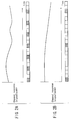
- FIGS. 2A and 2B are examples of graphs showing temporal variations of power as a channel response.
- the abscissa shows time, and the ordinate shows the intra-band average power of the channel response.
- FIG. 2A shows a temporal variation of power when the temporal variation of channel response is large
- FIG. 2B shows a temporal variation of power when the temporal variation of channel response is small.
- FIG. 2A An appropriate channel format corresponding to the temporal variation of power of the channel response is shown below each graph that shows the temporal variation of power of the channel response.
- FIG. 2A when the temporal variation of channel response is large, the frequency of insertion of channel response calculation preamble signal is increased. A channel response to be calculated to compensate for a data distortion can be updated in correspondence with the temporal variation of channel response. Therefore, a transmission error can be reduced. That is, when the temporal variation of channel response is large, a data length m between two channel response calculation preamble signals is set to be a small value, thus reducing transmission errors.
- the number of channel response calculation preamble signals inserted is varied in accordance with the temporal variation of channel response.
- FIG. 3 shows an example of the transmitted signal format in a radio communication system and radio transmission apparatus according to an embodiment of the present invention
- FIGS. 4, 5, and 6 are block diagrams.
- a control signal field written with control information which is used to demodulate data, is added to the transmitted signal format shown in FIG. 1. Since this control signal field is included, the receiving side can normally demodulate data by recognizing control information written in the control signal field.
- control signal field is inserted immediately after the first channel response calculation preamble signal, but its insertion position is not particularly limited.
- the control signal field contains a channel response calculation preamble signal output frequency field.
- the transmitting side writes transmission frequency information of channel response calculation preamble signals in the channel response calculation preamble signal output frequency field.
- the receiving side can detect the transmission frequency of channel response calculation preamble signals set at the transmitting side with reference to the contents of the channel response calculation preamble signal output frequency field, and can calculate a channel response at a correct timing.
- the receiving side can detect the output frequency, it can detect the position of the next channel response calculation preamble signal.
- the output frequency indicates that channel response calculation preamble signals are inserted every n symbols, for example.
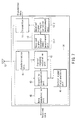
- FIG. 4 shows an example of a radio transmission apparatus according to the present invention.
- a base station 1 and terminal 2 have radio transmission apparatuses with the same arrangement.
- a transmitter 11 of the base station 1 transmits a transmitted signal which contains transmitted data and channel response calculation preamble signals in the transmission format shown in FIG. 3 from an antenna 12. Note that an optimal number of channel response calculation preamble signals is set in accordance with channel variation information output from a channel variation measurement unit 13.
- the terminal 2 receives the transmitted signal transmitted from the base station 1 by an antenna 22, and this signal is input to a receiver 24.
- the receiver 24 executes a reception process such as transmission distortion compensation and the like of a received signal using channel response calculation preamble signals, and outputs received data. Also, the receiver 24 outputs information used to measure a variation of channel response to a channel response variation measurement unit 23. As an input signal to the channel response variation measurement unit 23, a channel response calculation result or the like of the received signal is used.
- the channel response variation measurement unit 23 measures a variation of channel response, and outputs the measurement result to a transmitter 21.
- the measurement method of the variation of channel response includes:
- the transmitter 21 executes the same process as the transmission process of the base station 1, and outputs a transmitted signal to the base station 1 again. In this manner, a signal is transmitted between the base station 1 and terminal 2.
- FIG. 5 is a block diagram for explaining the transmitter 11 of the radio transmission apparatus shown in FIG. 4. Since the radio transmission apparatuses of the base station 1 and terminal 2 have the same arrangement, the transmitter 11 of the base station 1 will be explained as an example.
- the signal which is received by the antenna 12 and has the transmission format shown in FIG. 3 is input to a receiver 14.
- the receiver 14 executes a reception process of the received signal (to be described later), and outputs information used to measure a variation of channel response to a channel response variation measurement unit 13.
- a channel response variation measurement unit 13 As an input signal to the channel response variation measurement unit 13, for example, a channel response calculation result or the like is used.
- the channel response variation measurement unit 13 measures a variation of channel response, and outputs the measurement result to a channel response calculation preamble signal output frequency setting unit 31.
- the channel response calculation preamble signal output frequency setting unit 31 determines an optimal output frequency of channel response calculation preamble signals using the measurement result of the channel response variation, and informs a transmitted signal generator 32 and control signal field generator 33 of the output frequency of channel response calculation preamble signals.
- the control signal field generator 33 writes information of the channel response calculation preamble signal output frequency in the control signal field.
- transmitted data is converted into a data signal by a data signal generator 34, and the data signal, a synchronization preamble signal and channel response calculation preamble signals generated by a preamble signal generator 35, and the control signal field generated by the control signal field generator 33 are input to the transmitted signal generator 32.
- the transmitted signal generator 32 generates a transmitted signal based on the transmitted signal format shown in FIG. 3, and outputs it from the antenna 12.
- the channel response calculation preamble signals are inserted at the frequency set by the channel response calculation preamble signal output frequency setting unit 31. In this manner, the output frequency of channel response calculation preamble signals can be changed in accordance with a variation of channel response.
- FIG. 6 is a block diagram for explaining the receiver 14 of the radio transmission apparatus of the base station 1 shown in FIG. 4.
- the signal which is received by the antenna 12 and has the transmission format shown in FIG. 3 is input to a synchronization unit 41.
- the synchronization unit 41 synchronizes the received signal, and outputs the synchronized received signal to a channel response calculation unit 42 and distortion compensation unit 43.
- the channel response calculation preamble signal is input to the channel response calculation unit 42, and other signals are input to the distortion compensation unit 43.
- the channel response calculated by the channel response calculation unit 42 is input to the distortion compensation unit 43.
- the distortion compensation unit 43 compensates the received signal for any distortion using the channel response calculated by the channel response calculation unit 42.
- the control signal field is input to a control signal field analysis unit 44, which reads out control information required to demodulate, and supplies it to a data demodulation unit 45.
- the data demodulation unit 45 demodulates the distortion-compensated signal, and outputs the demodulated signal as received data.
- control signal field analysis unit 44 reads out information indicating the channel response calculation preamble signal output frequency, and informs the distortion compensation unit 43 and channel response calculation unit 42 of that channel response calculation preamble signal output frequency.
- the channel response calculation unit 42 supplies a channel response calculation preamble signal to the channel variation measurement unit 13, which measures the variation of channel response.
- the frequency of channel response calculation preamble signals to be inserted in the transmitted signal format by the transmitter 11 is changed in accordance with the measurement result.
- the frequency of channel response calculation preamble signals to be inserted in the signal format to be transmitted is changed in accordance with the channel variation, the channel response can be accurately calculated even when the channel variation is large, and a transmission error can be reduced.
- the channel response calculation preamble signal output frequency is sent to the distortion compensation unit 43 and channel response calculation unit 42, a channel response can be calculated at an accurate timing, and accurate distortion compensation can be made.
- the channel response calculation unit 42 can correctly recognize the reception timing of a channel response calculation preamble signal based on the received channel response calculation preamble signal output frequency information, and can calculate a channel response at a correct timing.
- the distortion correction unit 43 can correctly recognize the distortion compensation timing of data or the control signal field based on the received channel response calculation preamble signal output frequency.
- the distortion-compensated data is input to and demodulated by the demodulation unit 45. In this way, since the receiving side accurately recognizes the channel response calculation preamble signal output frequency, the data and control signal field can undergo distortion correction at correct timings. For this reason, even when the transmitting side varies the channel response calculation preamble signal output frequency, the data signal can be correctly demodulated.
- the transmitted signal format shown in FIG. 3 contains the channel response calculation preamble signal output frequency field used to inform, from the transmitting side, the receiving side of the channel response calculation preamble signal transmission frequency.
- information indicating the channel response calculation preamble signal output frequency may be contained in data.
- the channel response calculation preamble signal output frequency information is written in the transmitted signal.
- no channel response calculation preamble signal output frequency information may be written in the transmitted signal.
- the control signal field generator 33 of the transmitter, and the control signal analysis unit 44 of the receiver may be omitted.
- a method of calculating a correlation between each symbol and a channel response calculation preamble signal on the receiving side, and determining a symbol with high correlation as a channel response calculation preamble signal may be used.
- received signal strength (RSSI) information of a received signal may be used. Using the RSSI, a variation of channel response is measured.
- the channel response variation measurement unit 13 comprises a received signal strength measurement unit 13-1 and received signal strength variation measurement unit 13-2.
- the received signal strength measurement unit 13-1 measures the received signal strength of a received signal from the antenna 12, and the received signal strength variation measurement unit 13-2 measures a variation of received signal strength.
- the result of the received signal strength variation measurement unit 13-2 is input to the channel response calculation preamble signal output frequency setting unit 31 of the transmitter 11, thus setting the channel response calculation preamble signal output frequency in correspondence with the channel variation.
- the channel response calculation preamble signal output frequency is set inside the transmitter of the radio transmission apparatus that generates a transmitted signal.
- some radio transmission system may receive channel response calculation preamble signal output frequency information from a communication partner.
- the channel response variation measurement unit 13 and channel response calculation preamble frequency setting unit 31 may be omitted.
- Channel response calculation preamble signals may be inserted into the transmission format of a transmitted signal based on the channel response calculation preamble signal transmission frequency provided from the communication partner.
Landscapes
- Engineering & Computer Science (AREA)
- Power Engineering (AREA)
- Computer Networks & Wireless Communication (AREA)
- Signal Processing (AREA)
- Synchronisation In Digital Transmission Systems (AREA)
- Mobile Radio Communication Systems (AREA)
- Cable Transmission Systems, Equalization Of Radio And Reduction Of Echo (AREA)
- Digital Transmission Methods That Use Modulated Carrier Waves (AREA)
Abstract
Description
- The present invention relates to a radio communication apparatus, system and method for transmitting a radio signal in accordance with a transmission format in which a channel response calculation preamble signal serving as a reference is inserted.
- In recent years, a radio data communication system which can make high-speed data communications indoors or outdoors is required. In a radio communication system that implements high-speed data communications, distortions due to multi-pass interference, i.e., reception of a transmitted signal via various routes due to reflection by buildings, and the like, must be compensated for.
- When a transmitter transmits a known reference signal (channel response calculation preamble signal), a receiver calculates the channel response of the channel response calculation preamble signal. The channel response indicates the degree of distortion of phase, amplitude, or the like. The receiver multiplies the received data signal by the inverse characteristic of the channel response to compensate the received data signal for any distortion.
- Conventionally, an insertion method of the channel response calculation preamble signal is fixed in a system. This method includes a method of inserting a channel response calculation preamble signal at given time intervals, a method of inserting at the head of a packet or frame sent toward a given user, and the like.
- When a channel variation is large with respect to a packet length, the channel response calculation result obtained from the channel response calculation preamble signal has a large error from the channel distortion which is actually superposed on the data.
- In order to reduce such error, when the frequency of insertion of the channel response calculation preamble signal is increased, the data transmission efficiency lowers when the channel variation is small.
- As described above, in the conventional radio communication system and radio transmission apparatus, a large error is generated between the channel response calculated from the channel response calculation preamble signal and the channel distortion superposed on data due to a channel variation and, as a result, a reception error rate impairs. In order to reduce the error between the calculated channel response and distortion superposed on data, if the frequency of output of the channel response calculation preamble signal is fixed to be high, the data transmission efficiency lowers when the channel variation is small.
- It is, therefore, an object of the present invention to provide a radio communication apparatus, system and method, which can accurately calculate a channel response and can reduce any transmission error even when the channel variation is large.
- According to one aspect of the present invention, a radio communication method for transmitting a transmitted signal including a preamble signal used for calculating a channel response at a receiving side, comprises setting an output frequency of the preamble signal based on a temporal change of a radio propagation environment; and generating the transmitted signal by inserting the preamble signal in accordance with the output frequency.
- With this method, when the channel variation is large, the frequency of output of the channel response calculation preamble signal can be increased, and distortion correction that traces the channel variation along with an elapse of time can be made. On the other hand, when the channel variation is small, the frequency of output of the channel response calculation preamble signal can be decreased, and the data transmission efficiency can be improved.
- This summary of the invention does not necessarily describe all necessary features so that the invention may also be a sub-combination of these described features.
- The invention can be more fully understood from the following detailed description when taken in conjunction with the accompanying drawings, in which:
- FIG. 1 shows an example of the transmitted signal format of a radio communication system according to the present invention;
- FIG. 2A is a graph showing a temporal variation of (signal) power as a channel response when the variation is large;
- FIG. 2B is a graph showing a temporal variation of power as a channel response when the variation is small;
- FIG. 3 shows an example of the transmitted signal format of a radio communication system according to the present invention;
- FIG. 4 is a block diagram showing an embodiment of a radio transmission apparatus according to the present invention;
- FIG. 5 is a block diagram showing an embodiment of a radio transmission apparatus according to the present invention;
- FIG. 6 is a block diagram showing an embodiment of a radio transmission apparatus according to the present invention; and
- FIG. 7 is a block diagram showing another embodiment of a radio transmission apparatus according to the present invention.
-
- A radio transmission system and apparatus according to an embodiment of the present invention will be described hereinafter with reference to the accompanying drawings.
- FIG. 1 shows an example of the transmitted signal format of a radio communication system according to the present invention. A transmitted signal is made up of a synchronization preamble signal, at least one channel response calculation preamble signal (k signals in FIG. 1), and a plurality of data. The number of channel response calculation preamble signals is variable in accordance with a channel variation. The transmitting side controls the frequency of the channel response calculation preamble signal in accordance with the channel variation.
- FIGS. 2A and 2B are examples of graphs showing temporal variations of power as a channel response. The abscissa shows time, and the ordinate shows the intra-band average power of the channel response. FIG. 2A shows a temporal variation of power when the temporal variation of channel response is large, and FIG. 2B shows a temporal variation of power when the temporal variation of channel response is small.
- An appropriate channel format corresponding to the temporal variation of power of the channel response is shown below each graph that shows the temporal variation of power of the channel response. As shown in FIG. 2A, when the temporal variation of channel response is large, the frequency of insertion of channel response calculation preamble signal is increased. A channel response to be calculated to compensate for a data distortion can be updated in correspondence with the temporal variation of channel response. Therefore, a transmission error can be reduced. That is, when the temporal variation of channel response is large, a data length m between two channel response calculation preamble signals is set to be a small value, thus reducing transmission errors.
- On the other hand, as shown in FIG. 2B, when the temporal variation of channel response is small, the frequency of insertion of the channel response calculation preamble signal is decreased, since the channel response need not be calculated frequently. As a result, the ratio of the total length of channel response calculation preamble signals to the total data length decreases. Hence, the data transmission efficiency can be improved.
- In brief, according to the present invention, the number of channel response calculation preamble signals inserted is varied in accordance with the temporal variation of channel response.
- One embodiment of the present invention will be described below. FIG. 3 shows an example of the transmitted signal format in a radio communication system and radio transmission apparatus according to an embodiment of the present invention, and FIGS. 4, 5, and 6 are block diagrams.
- In the transmitted signal format shown in FIG. 3, a control signal field written with control information, which is used to demodulate data, is added to the transmitted signal format shown in FIG. 1. Since this control signal field is included, the receiving side can normally demodulate data by recognizing control information written in the control signal field.
- In FIG. 3, the control signal field is inserted immediately after the first channel response calculation preamble signal, but its insertion position is not particularly limited. The control signal field contains a channel response calculation preamble signal output frequency field. The transmitting side writes transmission frequency information of channel response calculation preamble signals in the channel response calculation preamble signal output frequency field. The receiving side can detect the transmission frequency of channel response calculation preamble signals set at the transmitting side with reference to the contents of the channel response calculation preamble signal output frequency field, and can calculate a channel response at a correct timing.
- That is, in the transmitted signal format shown in FIG. 3, since the synchronization preamble signal and channel response calculation preamble signal are always attached to the head of a packet. If the receiving side can detect the output frequency, it can detect the position of the next channel response calculation preamble signal. The output frequency indicates that channel response calculation preamble signals are inserted every n symbols, for example.
- FIG. 4 shows an example of a radio transmission apparatus according to the present invention. A
base station 1 andterminal 2 have radio transmission apparatuses with the same arrangement. Atransmitter 11 of thebase station 1 transmits a transmitted signal which contains transmitted data and channel response calculation preamble signals in the transmission format shown in FIG. 3 from anantenna 12. Note that an optimal number of channel response calculation preamble signals is set in accordance with channel variation information output from a channelvariation measurement unit 13. - The
terminal 2 receives the transmitted signal transmitted from thebase station 1 by an antenna 22, and this signal is input to areceiver 24. Thereceiver 24 executes a reception process such as transmission distortion compensation and the like of a received signal using channel response calculation preamble signals, and outputs received data. Also, thereceiver 24 outputs information used to measure a variation of channel response to a channel responsevariation measurement unit 23. As an input signal to the channel responsevariation measurement unit 23, a channel response calculation result or the like of the received signal is used. The channel responsevariation measurement unit 23 measures a variation of channel response, and outputs the measurement result to atransmitter 21. - Note that the measurement method of the variation of channel response includes:
- #1. a method of measuring a change in amplitude or phase from that of the previously calculated channel response every time a channel response is calculated, in consideration of a subcarrier (one or a plurality of subcarriers) that includes the calculated channel response;
- #2. a method of measuring the total (or average) power of respective symbols (as well as data), and measuring a change in amplitude (= power) or phase;
- #3. a method of measuring a change in amplitude or phase of a pilot carrier (for estimating a distortion) contained in each symbol; and the like.
-
- Furthermore, the
transmitter 21 executes the same process as the transmission process of thebase station 1, and outputs a transmitted signal to thebase station 1 again. In this manner, a signal is transmitted between thebase station 1 andterminal 2. - FIG. 5 is a block diagram for explaining the
transmitter 11 of the radio transmission apparatus shown in FIG. 4. Since the radio transmission apparatuses of thebase station 1 andterminal 2 have the same arrangement, thetransmitter 11 of thebase station 1 will be explained as an example. - The signal which is received by the
antenna 12 and has the transmission format shown in FIG. 3 is input to areceiver 14. Thereceiver 14 executes a reception process of the received signal (to be described later), and outputs information used to measure a variation of channel response to a channel responsevariation measurement unit 13. As an input signal to the channel responsevariation measurement unit 13, for example, a channel response calculation result or the like is used. The channel responsevariation measurement unit 13 measures a variation of channel response, and outputs the measurement result to a channel response calculation preamble signal outputfrequency setting unit 31. - The channel response calculation preamble signal output
frequency setting unit 31 determines an optimal output frequency of channel response calculation preamble signals using the measurement result of the channel response variation, and informs a transmittedsignal generator 32 and controlsignal field generator 33 of the output frequency of channel response calculation preamble signals. - The control
signal field generator 33 writes information of the channel response calculation preamble signal output frequency in the control signal field. - Furthermore, transmitted data is converted into a data signal by a
data signal generator 34, and the data signal, a synchronization preamble signal and channel response calculation preamble signals generated by apreamble signal generator 35, and the control signal field generated by the controlsignal field generator 33 are input to the transmittedsignal generator 32. The transmittedsignal generator 32 generates a transmitted signal based on the transmitted signal format shown in FIG. 3, and outputs it from theantenna 12. - At this time, the channel response calculation preamble signals are inserted at the frequency set by the channel response calculation preamble signal output
frequency setting unit 31. In this manner, the output frequency of channel response calculation preamble signals can be changed in accordance with a variation of channel response. - FIG. 6 is a block diagram for explaining the
receiver 14 of the radio transmission apparatus of thebase station 1 shown in FIG. 4. - Referring to FIG. 6, the signal which is received by the
antenna 12 and has the transmission format shown in FIG. 3 is input to asynchronization unit 41. Thesynchronization unit 41 synchronizes the received signal, and outputs the synchronized received signal to a channelresponse calculation unit 42 anddistortion compensation unit 43. When a channel response is calculated using a channel response calculation preamble signal, the channel response calculation preamble signal is input to the channelresponse calculation unit 42, and other signals are input to thedistortion compensation unit 43. - The channel response calculated by the channel
response calculation unit 42 is input to thedistortion compensation unit 43. Thedistortion compensation unit 43 compensates the received signal for any distortion using the channel response calculated by the channelresponse calculation unit 42. Of the distortion-compensated signal, the control signal field is input to a control signalfield analysis unit 44, which reads out control information required to demodulate, and supplies it to adata demodulation unit 45. Thedata demodulation unit 45 demodulates the distortion-compensated signal, and outputs the demodulated signal as received data. - Furthermore, the control signal
field analysis unit 44 reads out information indicating the channel response calculation preamble signal output frequency, and informs thedistortion compensation unit 43 and channelresponse calculation unit 42 of that channel response calculation preamble signal output frequency. - The channel
response calculation unit 42 supplies a channel response calculation preamble signal to the channelvariation measurement unit 13, which measures the variation of channel response. The frequency of channel response calculation preamble signals to be inserted in the transmitted signal format by thetransmitter 11 is changed in accordance with the measurement result. - In the radio transmission system with the above arrangement, since the frequency of channel response calculation preamble signals to be inserted in the signal format to be transmitted is changed in accordance with the channel variation, the channel response can be accurately calculated even when the channel variation is large, and a transmission error can be reduced.
- Since the channel response calculation preamble signal output frequency is sent to the
distortion compensation unit 43 and channelresponse calculation unit 42, a channel response can be calculated at an accurate timing, and accurate distortion compensation can be made. - Upon receiving this format, the channel
response calculation unit 42 can correctly recognize the reception timing of a channel response calculation preamble signal based on the received channel response calculation preamble signal output frequency information, and can calculate a channel response at a correct timing. Also, thedistortion correction unit 43 can correctly recognize the distortion compensation timing of data or the control signal field based on the received channel response calculation preamble signal output frequency. The distortion-compensated data is input to and demodulated by thedemodulation unit 45. In this way, since the receiving side accurately recognizes the channel response calculation preamble signal output frequency, the data and control signal field can undergo distortion correction at correct timings. For this reason, even when the transmitting side varies the channel response calculation preamble signal output frequency, the data signal can be correctly demodulated. - The transmitted signal format shown in FIG. 3 contains the channel response calculation preamble signal output frequency field used to inform, from the transmitting side, the receiving side of the channel response calculation preamble signal transmission frequency. In place of assuring the control signal field, as shown in FIG. 1, information indicating the channel response calculation preamble signal output frequency may be contained in data.
- In the above embodiment, the channel response calculation preamble signal output frequency information is written in the transmitted signal. However, in some cases, no channel response calculation preamble signal output frequency information may be written in the transmitted signal. In such case, the control
signal field generator 33 of the transmitter, and the controlsignal analysis unit 44 of the receiver may be omitted. - When the channel response calculation preamble signal output frequency is not available, a method of calculating a correlation between each symbol and a channel response calculation preamble signal on the receiving side, and determining a symbol with high correlation as a channel response calculation preamble signal may be used.
- As an input signal to the channel response
variation measurement unit 13, received signal strength (RSSI) information of a received signal may be used. Using the RSSI, a variation of channel response is measured. In this case, as shown in FIG. 7, the channel responsevariation measurement unit 13 comprises a received signal strength measurement unit 13-1 and received signal strength variation measurement unit 13-2. The received signal strength measurement unit 13-1 measures the received signal strength of a received signal from theantenna 12, and the received signal strength variation measurement unit 13-2 measures a variation of received signal strength. Furthermore, the result of the received signal strength variation measurement unit 13-2 is input to the channel response calculation preamble signal outputfrequency setting unit 31 of thetransmitter 11, thus setting the channel response calculation preamble signal output frequency in correspondence with the channel variation. - In the embodiment shown in FIG. 5, the channel response calculation preamble signal output frequency is set inside the transmitter of the radio transmission apparatus that generates a transmitted signal. However, some radio transmission system may receive channel response calculation preamble signal output frequency information from a communication partner. In such case, the channel response
variation measurement unit 13 and channel response calculation preamblefrequency setting unit 31 may be omitted. Channel response calculation preamble signals may be inserted into the transmission format of a transmitted signal based on the channel response calculation preamble signal transmission frequency provided from the communication partner.
Claims (12)
- A radio communication apparatus (1, 11) which transmits a transmitted signal including a preamble signal used for calculating a channel response at a receiving side, the transmission apparatus characterized by comprising:an output frequency setting unit (31) configured to set an output frequency of the preamble signal based on a temporal change of a radio propagation environment; anda transmitted signal generator (32) configured to generate the transmitted signal by inserting the preamble signal in accordance with the output frequency.
- The apparatus according to claim 1, characterized by further comprising:a receiver (14) configured to receive a radio signal; anda channel response variation measurement unit (13) configured to measure the temporal change of the radio propagation environment by using of the radio signal.
- The apparatus according to claim 1 or 2, characterized by further comprising a control signal field generator (33) configured to generate an output frequency field indicating the output frequency of the preamble signal, and wherein said transmitted signal generator inserts the output frequency field into the transmitted signal.
- The apparatus according to claim 3, characterized in that the output frequency setting unit (31) refers to the output frequency field contained in the received signal received by the receiver so as to control the output frequency based the field.
- An apparatus according to any one of the preceding claims, characterized in that the output frequency of the preamble signal is increased as the temporal variation of the radio propagation environment is getting larger.
- A radio communication system (1) for transmitting a radio signal with a transmission format in which a channel response calculation preamble signal serving as a reference upon reception is inserted, wherein an output frequency of channel response calculation preamble signals is varied in accordance with a temporal change in radio propagation environment.
- The system according to claim 6, characterized in that the transmission format includes an output frequency of channel response calculation preamble signals appended thereto.
- A radio communication method for transmitting a transmitted signal including a preamble signal used for calculating a channel response at a receiving side, the method characterized by comprising:setting an output frequency of the preamble signal based on a temporal change of a radio propagation environment of the channel; andgenerating the transmitted signal by inserting the preamble signal in accordance with the output frequency.
- The method according to claim 8, characterized by further comprising:receiving a radio signal by a receiver; andmeasuring the temporal change of the radio propagation environment of the channel by using of the radio signal.
- The method according to claim 8 or 9, characterized by further comprising generating an output frequency field indicating the output frequency of the preamble signal, the output frequency field being inserted into the transmitted signal.
- The method according to claim 10, characterized by further comprising:referring to the output frequency field contained in a received signal so as to control the output frequency based the field.
- A method according to any one of claims 8 to 11, characterized in that the output frequency of the preamble signal is increased as the temporal variation of the radio propagation environment is getting larger.
Applications Claiming Priority (2)
| Application Number | Priority Date | Filing Date | Title |
|---|---|---|---|
| JP2001087040 | 2001-03-26 | ||
| JP2001087040A JP3583730B2 (en) | 2001-03-26 | 2001-03-26 | Wireless communication system and wireless transmission device |
Publications (1)
| Publication Number | Publication Date |
|---|---|
| EP1249948A1 true EP1249948A1 (en) | 2002-10-16 |
Family
ID=18942335
Family Applications (1)
| Application Number | Title | Priority Date | Filing Date |
|---|---|---|---|
| EP02252160A Withdrawn EP1249948A1 (en) | 2001-03-26 | 2002-03-26 | Method and apparatus for maximising throughput via variable preamble allocation in a radio communications network |
Country Status (3)
| Country | Link |
|---|---|
| US (2) | US7403545B2 (en) |
| EP (1) | EP1249948A1 (en) |
| JP (1) | JP3583730B2 (en) |
Families Citing this family (10)
| Publication number | Priority date | Publication date | Assignee | Title |
|---|---|---|---|---|
| JP4050595B2 (en) * | 2002-11-11 | 2008-02-20 | 松下電器産業株式会社 | Wireless communication system, wireless communication method, and wireless communication apparatus |
| JP4407126B2 (en) * | 2003-01-09 | 2010-02-03 | ソニー株式会社 | Wireless communication system, wireless communication apparatus, wireless communication method, and computer program |
| JP2005020076A (en) * | 2003-06-23 | 2005-01-20 | Toshiba Corp | Communication method, transmission apparatus, and reception apparatus |
| US7400643B2 (en) * | 2004-02-13 | 2008-07-15 | Broadcom Corporation | Transmission of wide bandwidth signals in a network having legacy devices |
| JP2007288656A (en) * | 2006-04-19 | 2007-11-01 | Toyota Infotechnology Center Co Ltd | Radio communication apparatus, radio communication method, and radio communication program |
| JP4998169B2 (en) * | 2007-09-20 | 2012-08-15 | 富士通株式会社 | Wireless communication apparatus and propagation environment index dispersion suppression method |
| US20110116531A1 (en) * | 2009-05-11 | 2011-05-19 | Qualcomm Incorporated | Removal of multiplicative errors in frequency domain channel estimation for wireless repeaters |
| US9049065B2 (en) | 2009-05-11 | 2015-06-02 | Qualcomm Incorporated | Removal of ICI/ISI errors in frequency domain channel estimation for wireless repeaters |
| US20100284447A1 (en) * | 2009-05-11 | 2010-11-11 | Qualcomm Incorporated | Frequency domain feedback channel estimation for an interference cancellation repeater including sampling of non causal taps |
| JP6740718B2 (en) * | 2016-05-31 | 2020-08-19 | ソニー株式会社 | Wireless device and control method |
Citations (3)
| Publication number | Priority date | Publication date | Assignee | Title |
|---|---|---|---|---|
| US5566172A (en) * | 1992-12-30 | 1996-10-15 | Alcatel N.V. | Method for transmitting information at high speed by multiple burst allocation and associated receiving method and device |
| EP0903872A1 (en) * | 1997-09-17 | 1999-03-24 | Motorola, Inc. | Radio communication system having a frame transmission format and a method of providing the same |
| GB2329796A (en) * | 1997-09-29 | 1999-03-31 | Motorola Ltd | Increased data rate by reduction of training data |
Family Cites Families (41)
| Publication number | Priority date | Publication date | Assignee | Title |
|---|---|---|---|---|
| US3701023A (en) * | 1971-06-29 | 1972-10-24 | Ibm | Phase jitter extraction method for data transmission systems |
| US3715670A (en) * | 1971-12-20 | 1973-02-06 | Bell Telephone Labor Inc | Adaptive dc restoration in single-sideband data systems |
| US4002991A (en) * | 1975-01-29 | 1977-01-11 | Nippon Gakki Seizo Kabushiki Kaisha | Pilot signal extracting circuitry |
| US4706244A (en) * | 1985-01-15 | 1987-11-10 | Rockwell International Corporation | Frequency multiplexed telephone system |
| JP2715057B2 (en) * | 1994-04-05 | 1998-02-16 | クウォンタム・コーポレイション | Method and hard disk drive for eliminating undershoot induced timing phase step in data storage device |
| US5636252A (en) * | 1994-05-04 | 1997-06-03 | Samsung Electronics Co., Ltd. | Automatic gain control of radio receiver for receiving digital high-definition television signals |
| US5953370A (en) * | 1994-09-09 | 1999-09-14 | Omnipoint Corporation | Apparatus for receiving and correlating a spread spectrum signal |
| US5602833A (en) * | 1994-12-19 | 1997-02-11 | Qualcomm Incorporated | Method and apparatus for using Walsh shift keying in a spread spectrum communication system |
| JP3242287B2 (en) * | 1995-04-27 | 2001-12-25 | 株式会社日立製作所 | Wireless communication system and communication device |
| US5781540A (en) * | 1995-06-30 | 1998-07-14 | Hughes Electronics | Device and method for communicating in a mobile satellite system |
| US6356555B1 (en) * | 1995-08-25 | 2002-03-12 | Terayon Communications Systems, Inc. | Apparatus and method for digital data transmission using orthogonal codes |
| US6307868B1 (en) * | 1995-08-25 | 2001-10-23 | Terayon Communication Systems, Inc. | Apparatus and method for SCDMA digital data transmission using orthogonal codes and a head end modem with no tracking loops |
| EP0857400B1 (en) * | 1995-10-24 | 2005-04-13 | General Instrument Corporation | Variable length burst transmission over the physical layer of a multilayer transmission format |
| US6181497B1 (en) * | 1995-12-12 | 2001-01-30 | International Business Machines Corporation | System and method for providing nonadjacent redundancy synchronization bytes |
| US6359938B1 (en) * | 1996-10-31 | 2002-03-19 | Discovision Associates | Single chip VLSI implementation of a digital receiver employing orthogonal frequency division multiplexing |
| JP3575215B2 (en) * | 1997-03-05 | 2004-10-13 | 株式会社日立製作所 | Packet communication method and communication terminal device |
| US6259709B1 (en) * | 1997-05-02 | 2001-07-10 | Legerity, Inc. | Training preamble added to CT2 muxes in a CT2 wireless telecommunications system |
| US20020131393A1 (en) * | 1997-08-12 | 2002-09-19 | Andrew Baldridge | Graphic user interface for a radio location determination system |
| US6307840B1 (en) * | 1997-09-19 | 2001-10-23 | Qualcomm Incorporated | Mobile station assisted timing synchronization in CDMA communication system |
| US6144691A (en) * | 1997-09-30 | 2000-11-07 | Nokia Mobile Phones Limited | Method and apparatus for synchronizing to a direct sequence spread spectrum signal |
| US6370158B1 (en) * | 1997-11-14 | 2002-04-09 | Wireless Facilities, Inc. | Wireless T/E Transceiver frame signaling subcontroller |
| US6356598B1 (en) * | 1998-08-26 | 2002-03-12 | Thomson Licensing S.A. | Demodulator for an HDTV receiver |
| US6243369B1 (en) * | 1998-05-06 | 2001-06-05 | Terayon Communication Systems, Inc. | Apparatus and method for synchronizing an SCDMA upstream or any other type upstream to an MCNS downstream or any other type downstream with a different clock rate than the upstream |
| US6618452B1 (en) * | 1998-06-08 | 2003-09-09 | Telefonaktiebolaget Lm Ericsson (Publ) | Burst carrier frequency synchronization and iterative frequency-domain frame synchronization for OFDM |
| US6219377B1 (en) * | 1998-06-29 | 2001-04-17 | Legerity, Inc. | Method and apparatus for generating tones in a multi-tone modem |
| ID28508A (en) * | 1998-07-28 | 2001-05-31 | Samsung Electronics Co Ltd | PORTED SHIPPING IN CONTROL OF THE CDMA COMMUNICATION SYSTEM |
| US6252865B1 (en) * | 1998-10-02 | 2001-06-26 | Qualcomm, Inc. | Methods and apparatuses for fast power control of signals transmitted on a multiple access channel |
| US6246431B1 (en) * | 1999-01-26 | 2001-06-12 | Zenith Electronics Corporation | Digital television system for reducing co-channel interference in 8 MHZ channels |
| EP1159846A1 (en) * | 1999-03-08 | 2001-12-05 | Nokia Corporation | Method for establishing a communication between a user equipment and a radio network |
| US6169759B1 (en) * | 1999-03-22 | 2001-01-02 | Golden Bridge Technology | Common packet channel |
| US6606341B1 (en) * | 1999-03-22 | 2003-08-12 | Golden Bridge Technology, Inc. | Common packet channel with firm handoff |
| US6426973B1 (en) * | 1999-04-29 | 2002-07-30 | The Board Of Trustees Of The University Of Illinois | Differential minimum mean squared error communication signal compensation method |
| EP2259529B1 (en) * | 1999-07-28 | 2019-03-27 | Panasonic Intellectual Property Corporation of America | Apparatus for the transmission and reception of data and method for digital radio communication |
| US7027464B1 (en) * | 1999-07-30 | 2006-04-11 | Matsushita Electric Industrial Co., Ltd. | OFDM signal transmission scheme, and OFDM signal transmitter/receiver |
| WO2001061878A1 (en) * | 2000-02-17 | 2001-08-23 | Samsung Electronics Co., Ltd. | Apparatus and method for assigning a common packet channel in a cdma communication system |
| CN1193563C (en) * | 2000-02-22 | 2005-03-16 | 皇家菲利浦电子有限公司 | Multicarrier receiver with channel estimator |
| BRPI0106879B1 (en) * | 2000-06-21 | 2015-06-23 | Samsung Electronics Co Ltd | Access network device and terminal access device in high speed mobile communication system |
| US20020097780A1 (en) * | 2000-11-30 | 2002-07-25 | Odenwalder Joseph P. | Preamble generation |
| US7567781B2 (en) * | 2001-01-05 | 2009-07-28 | Qualcomm, Incorporated | Method and apparatus for power level adjustment in a wireless communication system |
| US7010065B2 (en) * | 2001-05-25 | 2006-03-07 | Hitachi Global Storage Technologies Netherlands B.V. | Method and apparatus for word synchronization with large coding distance and fault tolerance for PRML systems |
| EP1603134A1 (en) * | 2004-05-31 | 2005-12-07 | STMicroelectronics S.r.l. | Method to improve data reliability on hard disk drive systems |
-
2001
- 2001-03-26 JP JP2001087040A patent/JP3583730B2/en not_active Expired - Fee Related
-
2002
- 2002-03-22 US US10/102,835 patent/US7403545B2/en not_active Expired - Fee Related
- 2002-03-26 EP EP02252160A patent/EP1249948A1/en not_active Withdrawn
-
2008
- 2008-06-24 US US12/145,218 patent/US20090003494A1/en not_active Abandoned
Patent Citations (3)
| Publication number | Priority date | Publication date | Assignee | Title |
|---|---|---|---|---|
| US5566172A (en) * | 1992-12-30 | 1996-10-15 | Alcatel N.V. | Method for transmitting information at high speed by multiple burst allocation and associated receiving method and device |
| EP0903872A1 (en) * | 1997-09-17 | 1999-03-24 | Motorola, Inc. | Radio communication system having a frame transmission format and a method of providing the same |
| GB2329796A (en) * | 1997-09-29 | 1999-03-31 | Motorola Ltd | Increased data rate by reduction of training data |
Non-Patent Citations (1)
| Title |
|---|
| NANDA S ET AL: "ADAPTATION TECHNIQUES IN WIRELESS PACKET DATA SERVICES", IEEE COMMUNICATIONS MAGAZINE, IEEE SERVICE CENTER. PISCATAWAY, N.J, US, vol. 38, no. 1, January 2000 (2000-01-01), pages 54 - 64, XP000908338, ISSN: 0163-6804 * |
Also Published As
| Publication number | Publication date |
|---|---|
| JP3583730B2 (en) | 2004-11-04 |
| US20090003494A1 (en) | 2009-01-01 |
| US7403545B2 (en) | 2008-07-22 |
| US20020136189A1 (en) | 2002-09-26 |
| JP2002290295A (en) | 2002-10-04 |
Similar Documents
| Publication | Publication Date | Title |
|---|---|---|
| US20090003494A1 (en) | Radio communication system and apparatus | |
| CN102132508B (en) | Method and apparatus for determining an end of a subframe in a TDD system | |
| CA2120714C (en) | Method and apparatus of estimating channel quality in a receiver | |
| US6788737B1 (en) | Communication terminal apparatus, base station apparatus and communication method | |
| US7672221B2 (en) | Radio receiver and radio signal receiving method | |
| EP1164733B1 (en) | Channel constructing method and base station using the method | |
| US7321563B2 (en) | Apparatus and method for estimating a channel condition of a forward link in a mobile communication system | |
| CN102089997B (en) | Signal transmission parameter control using channel sounding | |
| US20030012308A1 (en) | Adaptive channel estimation for wireless systems | |
| JPH10257013A (en) | Receiver | |
| JP2015167385A (en) | Communication apparatus, communication method, and program | |
| EP1885080B1 (en) | Apparatus and method for synchronizing signal analyzer | |
| JP2001333123A (en) | Communication terminal and demodulation method | |
| US20100020864A1 (en) | Pulse transmitting device, pulse receiving device, pulse communication system, and pulse communication method | |
| US7599401B2 (en) | Transmission device and transmission method | |
| ATE340442T1 (en) | PARAMETER ESTIMATION FOR ADAPTIVE ANTENNA SYSTEM | |
| CN101889407A (en) | Method and device for receiving a data signal using a plurality of antennae | |
| EP1197026A1 (en) | Method and apparatus for channel estimation with transmit diversity | |
| JP2590441B2 (en) | Interference wave detection method | |
| JP3357653B2 (en) | Wireless receiver | |
| EP1881634B1 (en) | Adaptive communication for wireless networks | |
| JP2003115786A (en) | Digital radio communication equipment | |
| JP2005159849A (en) | Wireless communication system, base station equipment, and information exchanging method | |
| JP2002344366A (en) | Apparatus and method for equalizing | |
| US20050163092A1 (en) | Radio apparatus and base station apparatus |
Legal Events
| Date | Code | Title | Description |
|---|---|---|---|
| PUAI | Public reference made under article 153(3) epc to a published international application that has entered the european phase |
Free format text: ORIGINAL CODE: 0009012 |
|
| 17P | Request for examination filed |
Effective date: 20020417 |
|
| AK | Designated contracting states |
Kind code of ref document: A1 Designated state(s): AT BE CH CY DE DK ES FI FR GB GR IE IT LI LU MC NL PT SE TR |
|
| AX | Request for extension of the european patent |
Free format text: AL;LT;LV;MK;RO;SI |
|
| RTI1 | Title (correction) |
Free format text: METHOD AND APPARATUS FOR MAXIMISING THROUGHPUT VIA VARIABLE PREAMBLE ALLOCATION IN A RADIO COMMUNICATIONS NETWORK |
|
| 17Q | First examination report despatched |
Effective date: 20030410 |
|
| AKX | Designation fees paid |
Designated state(s): DE FR GB |
|
| STAA | Information on the status of an ep patent application or granted ep patent |
Free format text: STATUS: THE APPLICATION IS DEEMED TO BE WITHDRAWN |
|
| 18D | Application deemed to be withdrawn |
Effective date: 20040826 |