EP1249682A1 - Method and arrangement for keeping measuring device clean - Google Patents
Method and arrangement for keeping measuring device clean Download PDFInfo
- Publication number
- EP1249682A1 EP1249682A1 EP20020007833 EP02007833A EP1249682A1 EP 1249682 A1 EP1249682 A1 EP 1249682A1 EP 20020007833 EP20020007833 EP 20020007833 EP 02007833 A EP02007833 A EP 02007833A EP 1249682 A1 EP1249682 A1 EP 1249682A1
- Authority
- EP
- European Patent Office
- Prior art keywords
- measuring
- measuring element
- cleaning agent
- moving web
- web
- Prior art date
- Legal status (The legal status is an assumption and is not a legal conclusion. Google has not performed a legal analysis and makes no representation as to the accuracy of the status listed.)
- Withdrawn
Links
- 238000000034 method Methods 0.000 title claims abstract description 19
- 239000012459 cleaning agent Substances 0.000 claims abstract description 88
- 238000005259 measurement Methods 0.000 claims abstract description 24
- 239000007921 spray Substances 0.000 claims description 15
- 238000004140 cleaning Methods 0.000 claims description 7
- XLYOFNOQVPJJNP-UHFFFAOYSA-N water Substances O XLYOFNOQVPJJNP-UHFFFAOYSA-N 0.000 claims description 5
- 239000000428 dust Substances 0.000 description 13
- 239000003795 chemical substances by application Substances 0.000 description 7
- 239000012528 membrane Substances 0.000 description 5
- 238000007664 blowing Methods 0.000 description 3
- 239000002904 solvent Substances 0.000 description 3
- 238000009825 accumulation Methods 0.000 description 2
- 239000000498 cooling water Substances 0.000 description 2
- 230000007547 defect Effects 0.000 description 2
- 230000000694 effects Effects 0.000 description 2
- 239000000463 material Substances 0.000 description 2
- 239000000203 mixture Substances 0.000 description 2
- 230000003287 optical effect Effects 0.000 description 2
- 230000002085 persistent effect Effects 0.000 description 2
- 238000010926 purge Methods 0.000 description 2
- 238000005452 bending Methods 0.000 description 1
- 230000003749 cleanliness Effects 0.000 description 1
- 239000011248 coating agent Substances 0.000 description 1
- 238000005516 engineering process Methods 0.000 description 1
- 239000004744 fabric Substances 0.000 description 1
- 239000012535 impurity Substances 0.000 description 1
- 238000002347 injection Methods 0.000 description 1
- 239000007924 injection Substances 0.000 description 1
- 238000004519 manufacturing process Methods 0.000 description 1
- 238000000691 measurement method Methods 0.000 description 1
- 239000002184 metal Substances 0.000 description 1
- 231100000252 nontoxic Toxicity 0.000 description 1
- 230000003000 nontoxic effect Effects 0.000 description 1
- 230000002572 peristaltic effect Effects 0.000 description 1
- 239000011347 resin Substances 0.000 description 1
- 229920005989 resin Polymers 0.000 description 1
- 229910052594 sapphire Inorganic materials 0.000 description 1
- 239000010980 sapphire Substances 0.000 description 1
- 239000004065 semiconductor Substances 0.000 description 1
- 238000005507 spraying Methods 0.000 description 1
- 239000000126 substance Substances 0.000 description 1
- 238000009736 wetting Methods 0.000 description 1
Images

Classifications
-
- G—PHYSICS
- G01—MEASURING; TESTING
- G01B—MEASURING LENGTH, THICKNESS OR SIMILAR LINEAR DIMENSIONS; MEASURING ANGLES; MEASURING AREAS; MEASURING IRREGULARITIES OF SURFACES OR CONTOURS
- G01B21/00—Measuring arrangements or details thereof, where the measuring technique is not covered by the other groups of this subclass, unspecified or not relevant
- G01B21/02—Measuring arrangements or details thereof, where the measuring technique is not covered by the other groups of this subclass, unspecified or not relevant for measuring length, width, or thickness
- G01B21/06—Measuring arrangements or details thereof, where the measuring technique is not covered by the other groups of this subclass, unspecified or not relevant for measuring length, width, or thickness specially adapted for measuring length or width of objects while moving
-
- G—PHYSICS
- G01—MEASURING; TESTING
- G01N—INVESTIGATING OR ANALYSING MATERIALS BY DETERMINING THEIR CHEMICAL OR PHYSICAL PROPERTIES
- G01N21/00—Investigating or analysing materials by the use of optical means, i.e. using sub-millimetre waves, infrared, visible or ultraviolet light
- G01N21/01—Arrangements or apparatus for facilitating the optical investigation
- G01N21/15—Preventing contamination of the components of the optical system or obstruction of the light path
-
- G—PHYSICS
- G01—MEASURING; TESTING
- G01N—INVESTIGATING OR ANALYSING MATERIALS BY DETERMINING THEIR CHEMICAL OR PHYSICAL PROPERTIES
- G01N21/00—Investigating or analysing materials by the use of optical means, i.e. using sub-millimetre waves, infrared, visible or ultraviolet light
- G01N21/84—Systems specially adapted for particular applications
- G01N21/88—Investigating the presence of flaws or contamination
- G01N21/89—Investigating the presence of flaws or contamination in moving material, e.g. running paper or textiles
Definitions
- the invention relates to a method of keeping a measuring device clean, the measuring device being arranged to measure at least one property of a moving web and comprising at least one measuring head with at least one measuring element.
- the invention further relates to an arrangement for keeping a measuring device clean, the measuring device being arrangeable to measure at least one property of a moving web and comprising at least one measuring head with at least one measuring element.
- characteristics of paper quality are measured while a paper web to be manufactured is moving in a paper machine.
- Characteristics of paper quality are typically measured by means of traversing measuring devices, wherein measuring sensors are arranged in measuring carriages that traverse the paper web in the transverse direction thereof over the entire web width.
- measuring devices can also be stationary, in which case they constantly measure the same point in the transverse direction of the paper web. Dirt and dust build up as the paper web is formed and dried, and when the web moves at a high speed in the machine, dirt and dust are spread around the paper machine. This dirt and dust sticks onto measuring elements or measuring windows of the measuring device, which causes distortions in the measurement result.
- the dirt increases the number of holes the measuring device produces in the web.
- the problem of dirt has been further aggravated by the increased use of recycled pulp.
- Cleanliness of measuring devices is very important in order to obtain an accurate measurement result.
- the thickness of paper produced by a machine for producing newsprint is typically about 70 ⁇ m, and the external accuracy of measurement to be achieved varies between 0.3 and 1 ⁇ m. Dust and dirt gathering on the surface of a measuring element or a measuring window thus hinders the operation of a thickness gauge, in particular.
- Dirt also causes deviations in the measurement accuracy of profile, since even during one cycle of measurement which covers one back-and-forth movement over the paper web and which can last for example one minute the thickness of the layer of dust and dirt gathering on the surface of the measuring element or window can change at worst dozens of micrometers.
- Traversing measuring devices are currently cleaned during the standardization of the measuring device, i.e. when the measuring carriage and the devices therein are removed from the area of measurement outside the edge of the paper web.
- the measuring device in question and any other measuring devices in the same carriage are out of operation and no measurement results are thus obtained during cleaning.
- the measuring carriage is moved outside the web at desired intervals, typically for example once an hour, which is rather seldom regarding the accuracy of the measurement result.
- the measuring elements or windows can be cleaned for example manually by wiping them with a cleaning cloth or by blowing pressurized air onto the surface of the measuring element or window. Manual cleaning is laborious and requires service personnel.
- blowing pressurized air is not sufficient to remove accumulated dirt that is stuck onto the surface of the measuring element or window, such as a paper coating agent or resin provided in recycled pulp.
- the prior art also teaches blowing of pressurized air to keep a measuring window of a measuring device clean during measurement.
- An example of such an arrangement is disclosed in EP 0,974,828.
- An objective of the present invention is to provide a new type of method and arrangement for keeping a measuring device clean.
- the method according to the invention is characterized by cleaning the measuring element with cleaning agent during measurement.
- the arrangement according to the invention is characterized in that the arrangement comprises means for feeding cleaning agent to clean the measuring element during measurement.
- a measuring device arranged to measure at least one property of a moving web and comprising at least one measuring head with at least one measuring element, is kept clean by feeding cleaning agent to clean the surface of the measuring element during measurement.
- the measuring element is kept clean by feeding cleaning agent to the surface of the measuring element or the moving web and by bringing the web and the measuring element into contact with each other, so that the moving web wipes the surface of the measuring element with the cleaning agent.
- the measuring element is arranged to move up and down in the elevation of the measuring head, and the surface of the measuring element is brought into contact with the moving web by lifting or lowering the measuring element.
- the measuring element is fixed to the measuring head and the moving web is in continuous contact with the surface of the measuring element.
- cleaning agent is supplied to the surface of the moving web or the measuring element in the form of sprays with freely adjustable duration and interval.
- cleaning agent is continuously supplied to the surface of the moving web or the measuring element.
- cleaning agent is continuously supplied to the surface of the measuring element in order to prevent dust from sticking to the surface.
- An advantage of the invention is that the cleaning of the measuring element and thus the measuring head does not require the measuring device to be moved outside the web, but the device can be cleaned and/or kept clean during the use thereof in measuring web properties. Therefore the measurement does not have to be interrupted, and high accuracy of measurement can be maintained even in dirty conditions.
- the use of the cleaning agent helps remove even persistent dirt from the measuring element, thus reducing the number of holes and other defects caused in the web by the measuring element.
- cleaning agent can be fed either continuously or in the form of sprays with freely adjustable duration and intervals. The amount of cleaning agent needed to keep the measuring element clean is so small that it has no substantial effect on the web properties.
- Figure 1 is a schematic side view, in partial cross-section, of an arrangement for keeping a measuring element of a measuring device clean, the device measuring at least one property of a moving web.
- the measuring device 1 shown in Figure 1 is arranged to measure the thickness of a paper web 3 as the web moves in the direction of arrow A, i.e. in the machine direction.
- the paper web 3 is shown in Figure 1 in a substantially thicker form than it really has compared to the structure of the measuring device 1.
- the measuring device 1 comprises a first measuring head 2a and a second measuring head 2b, between which the paper web 3 is moving.
- the measuring heads 2a, 2b are provided in measuring carriages 4 that are arranged to reciprocate substantially continuously along beams 6 of a measuring frame 5 transversely to the machine direction of the paper machine along the entire width of the paper web 3.
- the measuring heads 2a, 2b can also be fixed either to the beams 6 or to some other suitable structure in the paper machine, so that they measure only one point of the paper web 3 in the lateral direction thereof.
- the first measuring head 2a is provided with a first measuring element 7a
- the second measuring head 2b is provided with a second measuring element 7b.
- the first measuring element 7a can be for example a coil
- the second measuring element 7b can be a button formed of a suitable material, such as a sapphire-coated metal plate, so that the distance between the measuring elements 7a and 7b can be determined in a manner known per se.
- the first measuring element 7a is fixed to the first measuring head 2a.
- the second measuring element 7b in turn is connected to the second measuring head 2b via a flexible membrane 8.
- the flexible membrane 8 enables the second measuring element 7b to move towards or away from the first measuring element 7a for example as the thickness of the paper web 3 varies.
- Figure 1 shows the measuring element 7b in a situation where the upper surface 9 of the element 7b touches the lower surface 21 of the paper web 3.
- the measuring element 7b is not necessarily in continuous contact with the paper web 3.
- Different measuring elements or sensors and their use to measure thickness or some other property of the paper web 3 are known per se to those skilled in the art, wherefore they will not be discussed in greater detail herein.
- the term 'measuring element' also includes a measuring window of an optical or a radiometric measuring device, for instance.
- the first measuring element 7a can be connected movably via a flexible membrane to the first measuring head 2a.
- the measuring head 2b is provided with a pump 10 for removing dust, dirt and other impurities gathering to the upper surface 9 of the measuring element 7b, the pump operating as a feeding unit for feeding cleaning agent to clean the measuring element 7b.
- the pump 10 which can be for example an injection pump, is arranged in the measuring head 2b right before the measuring element 7b in the direction of travel of the paper web 3.
- the measuring head 2b is provided with an opening 12, via which a spray of cleaning agent 13 supplied from a nozzle 11 of the pump 10 is able to flow outside the measuring head 2b and further to the lower surface 21 of the paper web 3.
- the paper web 3 moves forward and simultaneously wipes the upper surface 9 of the measuring element 7b clean by means of the cleaning agent contained on the lower surface 21 of the web.
- the dust and dirt gathering in the measuring element 7a can also be removed by means of the cleaning agent according to the invention by providing the measuring head 2a with similar means for supplying cleaning agent as shown in Figures 1 and 2.
- the paper web 3 can thus be made to move either near the measuring element 7a or to be in contact with the element continuously or intermittently.
- the measuring element 7a can also be connected to the measuring head 2a via a flexible membrane.
- the cleaning agent is stored in a cleaning agent tank 14, from which it is supplied via a transfer conduit 15 to the pump 10.
- the transfer conduit 15 can be for example a regular hose, which has very high bending and chemical resistance.
- the cleaning agent tank 14 can be arranged e.g. in the measuring carriage 4 or in the measuring frame 5.
- Pressurized air is also supplied to the pump 10 via a pressure air conduit 16 in order to split the cleaning agent in the spray of cleaning agent 13 into sufficiently small droplets.
- the pressure air conduit 16 can be for example a flexible hose. If pressurized air or purge air is supplied to the measuring carriage 4 for some other reason than for splitting the cleaning agent into droplets, these sources of pressurized air and purge air can also be used to reduce the agent into droplets.
- the equipment does not require a new pressure air conduit.
- the operation of the pump 10 is preferably controlled by a control unit 17 based on semiconductor technology and comprising as adjustable variables the duration and interval of the sprays of cleaning agent 13. If the amount of dirt and dust gathering for example during one minute is 20 ⁇ m, and the desired measurement accuracy allows a dirt layer of at most 1 micrometer at the surface of the measuring element, the interval between the sprays of cleaning agent 13 could be set in this case to three seconds, for example.
- the duration and flow volume rate of the spray of cleaning agent 13 are determined so that the amount of the agent to be sprayed does not affect the properties of the paper web 3.
- the duration of the spray of cleaning agent 13 could be for example 0.1 s, and the amount of the agent to be sprayed could be e.g. 33 ml per hour.
- Cleaning agent can also be sprayed continuously, which means that the spray 13 is continuous.
- the nozzle 11 of the pump 10 can be implemented in several manners.
- the nozzle 11 is preferably knife-like.
- a knife-like nozzle produces a spray of cleaning agent 13, which is very narrow in the direction of travel of the paper web 3 denoted by arrow A, but wide in the transverse direction of the web 3.
- two or more pumps 10 and openings 12 can be provided in parallel in the measuring head 2b, so that a very wide spray of cleaning agent can be supplied to the lower surface 21 of the paper web 3.
- one pump 10 can be used to supply cleaning agent via several nozzles 11 and openings 12.
- the spray of cleaning agent 13 is supplied directly to the upper surface 9 of the measuring element 7b so as to prevent dust and dirt from sticking thereto.
- the dry paper web 3 can be brought into contact with the measuring element 7b, whereafter the paper web 3 wipes away the cleaning agent together with the dirt and dust from the upper surface 9 of the measuring element 7b.
- An advantage of the invention is that the measuring element and thus the measuring head can be cleaned or kept clean while the measuring device keeps measuring properties of a moving web without interruptions. Consequently, high accuracy of measurement can be maintained continuously even in dirty conditions of use. By means of cleaning agent even persistent dirt can be easily wiped off the measuring element, which reduces the number of holes or other defects caused by the measuring element in the web.
- Figure 3 shows schematically another arrangement for cleaning the measuring element 7b, viewed in partial cross-section from the front of the measuring head 2b.
- Figure 4 shows schematically a top view of the measuring head 2b according to Figure 3.
- the measuring element 7b is fixed to the measuring head 2b, and the paper web 3 is in continuous contact with the measuring element 7b.
- the measuring element 7b comprises two contact surfaces 22, which protrude from the rest of the structure of the element.
- the measuring head 2b is provided with two openings 12 at the contact surfaces 22 right before the measuring element 7b with respect to the direction of travel of the web, and cleaning agent can be supplied to the paper web 3 via the openings.
- the measuring head 2b comprises a bypass manifold 18 used as a feeding unit.
- a feed hose 19 is provided from the bypass manifold 18 to each opening 12.
- the cleaning agent is transferred from the cleaning agent tank 14 via the transfer conduit 15 to the bypass manifold 18, which distributes the agent into feed nozzles 19a.
- the material of the feed nozzles 19a is selected such that the nozzles do not affect the measurement result.
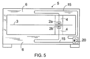
- the cleaning agent tank 14 can be located for example at the end of the beam 6, as shown schematically in Figure 5, and the cleaning agent is thus transferred to the bypass manifold 18 at the measuring head 2b by means of a pump 20 provided in the cleaning agent tank 14.
- the pump 20 can also be located in the transfer conduit 15.
- Cleaning agent can be administered continuously, i.e.
- a continuous flow of cleaning agent is supplied to the paper web 3, or cleaning agent can be fed at predetermined intervals.
- the pump 20 can be of either feeding or continuous type, and the output of the pump can be adjusted.
- a small cleaning agent tank 14 and a pump 20 optionally provided therein can also be arranged in the measuring carriage 4.
- the pump 20 can be any one of a number of pump alternatives.
- the pump 20 can be for example a peristaltic pump, a piston pump or a gear pump.
- the transfer of cleaning agent does not necessarily require a pump, but a pressurized water network, such as a cooling water conduit, is also suitable for the purpose.
- the nozzle 11 can be designed to feed cleaning agent, or the nozzle 11 can provide a continuous spray of cleaning agent.
- a feed nozzle 11 is controlled by the aforementioned control unit 17.
- the cleaning agent is non-toxic and odourless, it provides good wetting, and it also has low surface tension.
- the agent is also volatile, wherefore it does not remain in the paper.
- a particularly suitable cleaning agent is water, since the agent can thus be obtained from the cooling water conduit of the measuring device 1 and no separate cleaning agent tank is needed.
- the cleaning agent can also be a solvent fulfilling the aforementioned requirements, or a mixture of a solvent and water. In such a case the solvent requires a separate tank or a feeding device.
- the only essential requirement for the composition of the cleaning agent is that the agent should not interfere with the operation of the measuring device, i.e. in the case of the thickness gauge set forth in the examples, the cleaning agent must have such magnetic properties that it does not affect the measurement result.
- the cleaning agent can also prevent accumulation of dirt, which means that cleaning agent is supplied to the surface of the measuring element 7b to prevent dirt and dust from sticking thereto. Therefore the arrangement according to the invention can be applied in optical measuring devices where the measuring element, or the measuring window thereof, does not touch the surface of the moving web. In such a case the measuring element is cleaned by spraying cleaning agent to the surface of the measuring element or between the web and the element to prevent dirt from sticking to the surface of the element.
- the cleaning agent to be sprayed can naturally also remove dirt from the surface of the measuring element.
- the moving web to be measured can be a kind of plastic membrane or some other plastic-based web.
- the moving web is preferably a paper, board or pulp web.
- the arrangement shown in Figures 1 and 2 can be used in connection with a stationary measuring element, and the arrangement shown in Figures 3 and 4 can be used in connection with a moving measuring element.
- the measuring device can comprise only one measuring head instead of two, and the measuring element can be arranged either immovably or movably in the measuring head.
- the unit for feeding cleaning agent can be placed in the measuring carriage, such that the feeding unit feeds cleaning agent to the web before the web moves between the measuring heads.
- the measuring element can also be provided with small channels, through which the cleaning agent can be conducted to the surface of paper as the measuring element touches the paper web.
- a method and an arrangement for keeping a measuring device clean the measuring device (1) being arranged to measure at least one property of a moving web and comprising at least one measuring head (2a, 2b) with at least one measuring element (7a, 7b) that is cleaned with cleaning agent during measurement.
Landscapes
- Physics & Mathematics (AREA)
- General Physics & Mathematics (AREA)
- Health & Medical Sciences (AREA)
- Life Sciences & Earth Sciences (AREA)
- Chemical & Material Sciences (AREA)
- Analytical Chemistry (AREA)
- Biochemistry (AREA)
- General Health & Medical Sciences (AREA)
- Immunology (AREA)
- Pathology (AREA)
- Engineering & Computer Science (AREA)
- Textile Engineering (AREA)
- Paper (AREA)
Abstract
A method and an arrangement for keeping a measuring
device clean, the measuring device (1) being arranged to
measure at least one property of a moving web and comprising
at least one measuring head (2a, 2b) with at least
one measuring element (7a, 7b) that is cleaned with cleaning
agent during measurement.
Description
- The invention relates to a method of keeping a measuring device clean, the measuring device being arranged to measure at least one property of a moving web and comprising at least one measuring head with at least one measuring element.
- The invention further relates to an arrangement for keeping a measuring device clean, the measuring device being arrangeable to measure at least one property of a moving web and comprising at least one measuring head with at least one measuring element.
- In papermaking, characteristics of paper quality, such as thickness, are measured while a paper web to be manufactured is moving in a paper machine. Characteristics of paper quality are typically measured by means of traversing measuring devices, wherein measuring sensors are arranged in measuring carriages that traverse the paper web in the transverse direction thereof over the entire web width. However, measuring devices can also be stationary, in which case they constantly measure the same point in the transverse direction of the paper web. Dirt and dust build up as the paper web is formed and dried, and when the web moves at a high speed in the machine, dirt and dust are spread around the paper machine. This dirt and dust sticks onto measuring elements or measuring windows of the measuring device, which causes distortions in the measurement result. Furthermore, in the case of high-speed paper machines and thin paper grades the dirt increases the number of holes the measuring device produces in the web. The problem of dirt has been further aggravated by the increased use of recycled pulp. Cleanliness of measuring devices is very important in order to obtain an accurate measurement result. For example, the thickness of paper produced by a machine for producing newsprint is typically about 70 µm, and the external accuracy of measurement to be achieved varies between 0.3 and 1 µm. Dust and dirt gathering on the surface of a measuring element or a measuring window thus hinders the operation of a thickness gauge, in particular. Dirt also causes deviations in the measurement accuracy of profile, since even during one cycle of measurement which covers one back-and-forth movement over the paper web and which can last for example one minute the thickness of the layer of dust and dirt gathering on the surface of the measuring element or window can change at worst dozens of micrometers.
- The effect of dirt and dust on the measurement result has been compensated by standardizing the measuring devices at regular intervals. However, in view of an accurate measurement result this method is highly unreliable since new dirt accumulates and old dirt is removed continuously, and the amount of dirt can thus vary a great deal between rounds of standardization. The standardization trend exhibits great changes, yet there may have been even greater variations between instants of standardization than what the trend shows, such variations resulting from temporary accumulation of dirt.
- Traversing measuring devices are currently cleaned during the standardization of the measuring device, i.e. when the measuring carriage and the devices therein are removed from the area of measurement outside the edge of the paper web. The measuring device in question and any other measuring devices in the same carriage are out of operation and no measurement results are thus obtained during cleaning. The measuring carriage is moved outside the web at desired intervals, typically for example once an hour, which is rather seldom regarding the accuracy of the measurement result. The measuring elements or windows can be cleaned for example manually by wiping them with a cleaning cloth or by blowing pressurized air onto the surface of the measuring element or window. Manual cleaning is laborious and requires service personnel. On the other hand, blowing pressurized air is not sufficient to remove accumulated dirt that is stuck onto the surface of the measuring element or window, such as a paper coating agent or resin provided in recycled pulp. The prior art also teaches blowing of pressurized air to keep a measuring window of a measuring device clean during measurement. An example of such an arrangement is disclosed in EP 0,974,828.
- An objective of the present invention is to provide a new type of method and arrangement for keeping a measuring device clean.
- The method according to the invention is characterized by cleaning the measuring element with cleaning agent during measurement.
- The arrangement according to the invention is characterized in that the arrangement comprises means for feeding cleaning agent to clean the measuring element during measurement.
- According to the basic idea of the invention, a measuring device arranged to measure at least one property of a moving web and comprising at least one measuring head with at least one measuring element, is kept clean by feeding cleaning agent to clean the surface of the measuring element during measurement. According to a preferred embodiment of the invention, the measuring element is kept clean by feeding cleaning agent to the surface of the measuring element or the moving web and by bringing the web and the measuring element into contact with each other, so that the moving web wipes the surface of the measuring element with the cleaning agent. According to another preferred embodiment of the invention, the measuring element is arranged to move up and down in the elevation of the measuring head, and the surface of the measuring element is brought into contact with the moving web by lifting or lowering the measuring element. According to a third preferred embodiment of the invention, the measuring element is fixed to the measuring head and the moving web is in continuous contact with the surface of the measuring element. According to a fourth preferred embodiment of the invention, cleaning agent is supplied to the surface of the moving web or the measuring element in the form of sprays with freely adjustable duration and interval. According to a fifth preferred embodiment of the invention, cleaning agent is continuously supplied to the surface of the moving web or the measuring element. According to a sixth preferred embodiment of the invention, cleaning agent is continuously supplied to the surface of the measuring element in order to prevent dust from sticking to the surface.
- An advantage of the invention is that the cleaning of the measuring element and thus the measuring head does not require the measuring device to be moved outside the web, but the device can be cleaned and/or kept clean during the use thereof in measuring web properties. Therefore the measurement does not have to be interrupted, and high accuracy of measurement can be maintained even in dirty conditions. The use of the cleaning agent helps remove even persistent dirt from the measuring element, thus reducing the number of holes and other defects caused in the web by the measuring element. Depending on the speed at which the measuring element becomes soiled and on the conditions of use, cleaning agent can be fed either continuously or in the form of sprays with freely adjustable duration and intervals. The amount of cleaning agent needed to keep the measuring element clean is so small that it has no substantial effect on the web properties.
- The arrangement according to the invention can be used similarly in connection with board manufacture, and in this specification the term 'paper' also refers to board and pulp.
- The invention will be described in more detail in the accompanying drawings, in which
- Figure 1 shows schematically an arrangement according to the invention for keeping a measuring device clean, viewed in partial cross-section from the side of the measuring device,
- Figure 2 shows schematically the arrangement according to Figure 1, viewed from above a second measuring head of the measuring device,
- Figure 3 shows schematically another arrangement according to the invention, viewed in partial cross-section from the front of the measuring head of the measuring device,
- Figure 4 shows schematically the arrangement according to Figure 3, viewed from above the measuring head, and
- Figure 5 is a schematic front view of a measuring frame in a paper machine.
-
- Figure 1 is a schematic side view, in partial cross-section, of an arrangement for keeping a measuring element of a measuring device clean, the device measuring at least one property of a moving web. The measuring device 1 shown in Figure 1 is arranged to measure the thickness of a
paper web 3 as the web moves in the direction of arrow A, i.e. in the machine direction. For the sake of clarity, thepaper web 3 is shown in Figure 1 in a substantially thicker form than it really has compared to the structure of the measuring device 1. The measuring device 1 comprises afirst measuring head 2a and a second measuringhead 2b, between which thepaper web 3 is moving. As shown schematically in Figure 5, themeasuring heads carriages 4 that are arranged to reciprocate substantially continuously alongbeams 6 of ameasuring frame 5 transversely to the machine direction of the paper machine along the entire width of thepaper web 3. Themeasuring heads beams 6 or to some other suitable structure in the paper machine, so that they measure only one point of thepaper web 3 in the lateral direction thereof. Thefirst measuring head 2a is provided with afirst measuring element 7a, and thesecond measuring head 2b is provided with asecond measuring element 7b. Thefirst measuring element 7a can be for example a coil, and thesecond measuring element 7b can be a button formed of a suitable material, such as a sapphire-coated metal plate, so that the distance between themeasuring elements first measuring element 7a is fixed to the first measuringhead 2a. Thesecond measuring element 7b in turn is connected to the second measuringhead 2b via aflexible membrane 8. Theflexible membrane 8 enables thesecond measuring element 7b to move towards or away from thefirst measuring element 7a for example as the thickness of thepaper web 3 varies. Figure 1 shows themeasuring element 7b in a situation where theupper surface 9 of theelement 7b touches thelower surface 21 of thepaper web 3. However, themeasuring element 7b is not necessarily in continuous contact with thepaper web 3. Different measuring elements or sensors and their use to measure thickness or some other property of thepaper web 3 are known per se to those skilled in the art, wherefore they will not be discussed in greater detail herein. Moreover, the term 'measuring element' also includes a measuring window of an optical or a radiometric measuring device, for instance. In addition to thesecond measuring element 7b, thefirst measuring element 7a can be connected movably via a flexible membrane to thefirst measuring head 2a. - In the arrangement of Figure 1, which is shown schematically in Figure 2 viewed from above the
second measuring head 2b, themeasuring head 2b is provided with apump 10 for removing dust, dirt and other impurities gathering to theupper surface 9 of themeasuring element 7b, the pump operating as a feeding unit for feeding cleaning agent to clean themeasuring element 7b. Thepump 10, which can be for example an injection pump, is arranged in themeasuring head 2b right before themeasuring element 7b in the direction of travel of thepaper web 3. Themeasuring head 2b is provided with anopening 12, via which a spray ofcleaning agent 13 supplied from a nozzle 11 of thepump 10 is able to flow outside the measuringhead 2b and further to thelower surface 21 of thepaper web 3. After the measuringelement 7b has been lifted into the position shown in Figure 1, where the measuringelement 7b touches thelower surface 21 of thepaper web 3, thepaper web 3 moves forward and simultaneously wipes theupper surface 9 of the measuringelement 7b clean by means of the cleaning agent contained on thelower surface 21 of the web. The dust and dirt gathering in the measuringelement 7a can also be removed by means of the cleaning agent according to the invention by providing the measuringhead 2a with similar means for supplying cleaning agent as shown in Figures 1 and 2. Thepaper web 3 can thus be made to move either near the measuringelement 7a or to be in contact with the element continuously or intermittently. The measuringelement 7a can also be connected to the measuringhead 2a via a flexible membrane. - The cleaning agent is stored in a
cleaning agent tank 14, from which it is supplied via atransfer conduit 15 to thepump 10. Thetransfer conduit 15 can be for example a regular hose, which has very high bending and chemical resistance. Thecleaning agent tank 14 can be arranged e.g. in the measuringcarriage 4 or in the measuringframe 5. Pressurized air is also supplied to thepump 10 via apressure air conduit 16 in order to split the cleaning agent in the spray of cleaningagent 13 into sufficiently small droplets. Thepressure air conduit 16 can be for example a flexible hose. If pressurized air or purge air is supplied to the measuringcarriage 4 for some other reason than for splitting the cleaning agent into droplets, these sources of pressurized air and purge air can also be used to reduce the agent into droplets. In such a case, for example when an existing measuring carriage is provided with means for feeding cleaning agent, the equipment does not require a new pressure air conduit. The operation of thepump 10 is preferably controlled by acontrol unit 17 based on semiconductor technology and comprising as adjustable variables the duration and interval of the sprays of cleaningagent 13. If the amount of dirt and dust gathering for example during one minute is 20 µm, and the desired measurement accuracy allows a dirt layer of at most 1 micrometer at the surface of the measuring element, the interval between the sprays of cleaningagent 13 could be set in this case to three seconds, for example. The duration and flow volume rate of the spray of cleaningagent 13 are determined so that the amount of the agent to be sprayed does not affect the properties of thepaper web 3. In this case the duration of the spray of cleaningagent 13 could be for example 0.1 s, and the amount of the agent to be sprayed could be e.g. 33 ml per hour. Cleaning agent can also be sprayed continuously, which means that thespray 13 is continuous. - The nozzle 11 of the
pump 10 can be implemented in several manners. The nozzle 11 is preferably knife-like. A knife-like nozzle produces a spray of cleaningagent 13, which is very narrow in the direction of travel of thepaper web 3 denoted by arrow A, but wide in the transverse direction of theweb 3. If the area to be cleaned is very wide in the lateral direction of thepaper web 3, two ormore pumps 10 andopenings 12 can be provided in parallel in the measuringhead 2b, so that a very wide spray of cleaning agent can be supplied to thelower surface 21 of thepaper web 3. Furthermore, onepump 10 can be used to supply cleaning agent via several nozzles 11 andopenings 12. According to one implementation of the nozzle 11, when the measuringelement 7b does not touch thepaper web 3, the spray of cleaningagent 13 is supplied directly to theupper surface 9 of the measuringelement 7b so as to prevent dust and dirt from sticking thereto. If desired, thedry paper web 3 can be brought into contact with the measuringelement 7b, whereafter thepaper web 3 wipes away the cleaning agent together with the dirt and dust from theupper surface 9 of the measuringelement 7b. - An advantage of the invention is that the measuring element and thus the measuring head can be cleaned or kept clean while the measuring device keeps measuring properties of a moving web without interruptions. Consequently, high accuracy of measurement can be maintained continuously even in dirty conditions of use. By means of cleaning agent even persistent dirt can be easily wiped off the measuring element, which reduces the number of holes or other defects caused by the measuring element in the web.
- Figure 3 shows schematically another arrangement for cleaning the measuring
element 7b, viewed in partial cross-section from the front of the measuringhead 2b. Figure 4 shows schematically a top view of the measuringhead 2b according to Figure 3. In the arrangement shown in Figures 3 and 4, the measuringelement 7b is fixed to the measuringhead 2b, and thepaper web 3 is in continuous contact with the measuringelement 7b. The measuringelement 7b comprises twocontact surfaces 22, which protrude from the rest of the structure of the element. The measuringhead 2b is provided with twoopenings 12 at the contact surfaces 22 right before the measuringelement 7b with respect to the direction of travel of the web, and cleaning agent can be supplied to thepaper web 3 via the openings. The measuringhead 2b comprises abypass manifold 18 used as a feeding unit. Afeed hose 19 is provided from thebypass manifold 18 to eachopening 12. The cleaning agent is transferred from thecleaning agent tank 14 via thetransfer conduit 15 to thebypass manifold 18, which distributes the agent intofeed nozzles 19a. In the case of the thickness gauge disclosed in this example, the material of thefeed nozzles 19a is selected such that the nozzles do not affect the measurement result. Thecleaning agent tank 14 can be located for example at the end of thebeam 6, as shown schematically in Figure 5, and the cleaning agent is thus transferred to thebypass manifold 18 at the measuringhead 2b by means of apump 20 provided in thecleaning agent tank 14. Thepump 20 can also be located in thetransfer conduit 15. Cleaning agent can be administered continuously, i.e. a continuous flow of cleaning agent is supplied to thepaper web 3, or cleaning agent can be fed at predetermined intervals. Thus, thepump 20 can be of either feeding or continuous type, and the output of the pump can be adjusted. Depending on the consumption of cleaning agent, a smallcleaning agent tank 14 and apump 20 optionally provided therein can also be arranged in the measuringcarriage 4. Thepump 20 can be any one of a number of pump alternatives. Thepump 20 can be for example a peristaltic pump, a piston pump or a gear pump. Furthermore, the transfer of cleaning agent does not necessarily require a pump, but a pressurized water network, such as a cooling water conduit, is also suitable for the purpose. In such a case the nozzle 11 can be designed to feed cleaning agent, or the nozzle 11 can provide a continuous spray of cleaning agent. A feed nozzle 11 is controlled by theaforementioned control unit 17. - The cleaning agent is non-toxic and odourless, it provides good wetting, and it also has low surface tension. The agent is also volatile, wherefore it does not remain in the paper. A particularly suitable cleaning agent is water, since the agent can thus be obtained from the cooling water conduit of the measuring device 1 and no separate cleaning agent tank is needed. The cleaning agent can also be a solvent fulfilling the aforementioned requirements, or a mixture of a solvent and water. In such a case the solvent requires a separate tank or a feeding device. The only essential requirement for the composition of the cleaning agent is that the agent should not interfere with the operation of the measuring device, i.e. in the case of the thickness gauge set forth in the examples, the cleaning agent must have such magnetic properties that it does not affect the measurement result. The cleaning agent can also prevent accumulation of dirt, which means that cleaning agent is supplied to the surface of the measuring
element 7b to prevent dirt and dust from sticking thereto. Therefore the arrangement according to the invention can be applied in optical measuring devices where the measuring element, or the measuring window thereof, does not touch the surface of the moving web. In such a case the measuring element is cleaned by spraying cleaning agent to the surface of the measuring element or between the web and the element to prevent dirt from sticking to the surface of the element. The cleaning agent to be sprayed can naturally also remove dirt from the surface of the measuring element. - The drawings and the related description are only intended to illustrate the inventive idea. The details of the invention can vary within the scope of the claims. Thus, instead of a
paper web 3, the moving web to be measured can be a kind of plastic membrane or some other plastic-based web. However, the moving web is preferably a paper, board or pulp web. It is also evident that the arrangement shown in Figures 1 and 2 can be used in connection with a stationary measuring element, and the arrangement shown in Figures 3 and 4 can be used in connection with a moving measuring element. Furthermore, depending on the property of the moving web to be monitored and the measurement method of the measuring elements required to monitor the property, the measuring device can comprise only one measuring head instead of two, and the measuring element can be arranged either immovably or movably in the measuring head. Instead of the measuring head, the unit for feeding cleaning agent can be placed in the measuring carriage, such that the feeding unit feeds cleaning agent to the web before the web moves between the measuring heads. The measuring element can also be provided with small channels, through which the cleaning agent can be conducted to the surface of paper as the measuring element touches the paper web. - A method and an arrangement for keeping a measuring
device clean, the measuring device (1) being arranged to
measure at least one property of a moving web and comprising at least one measuring head (2a, 2b) with at least
one measuring element (7a, 7b) that is cleaned with cleaning agent during measurement. - (Figure 1)
Claims (30)
- A method of keeping a measuring device clean, the measuring device (1) being arranged to measure at least one property of a moving web and comprising at least one measuring head (2a, 2b) with at least one measuring element (7a, 7b), characterized by cleaning the measuring element (7a, 7b) with cleaning agent during measurement.
- A method according to claim 1, characterized by feeding cleaning agent to the surface of the measuring element (7a, 7b) or the moving web, and bringing the moving web and the measuring element (7a, 7b) into contact so that the moving web cleans the surface of the measuring element (7a, 7b) with the cleaning agent.
- A method according to claim 2, characterized in that the moving web wipes the surface of the measuring element (7a, 7b) with the cleaning agent.
- A method according to any one of the preceding claims, characterized in that the measuring element (7a, 7b) is in contact or is brought into contact with the moving web.
- A method according to claim 4, characterized in that the measuring element (7a, 7b) is arranged to move up and down in the elevation of the measuring head (2a, 2b), and the measuring element (7a, 7b) is brought into contact with the moving web by lifting or lowering the measuring element (7a, 7b).
- A method according to any one of claims 1 to 3, characterized in that the measuring element (7a, 7b) is fixed, and the moving web is in continuous contact with the measuring element (7a, 7b).
- A method according to any one of the preceding claims, characterized by feeding cleaning agent to the surface of the moving web or the measuring element (7a, 7b) in the form of sprays of cleaning agent (13) with freely adjustable duration and interval.
- A method according to any one of claims 1 to 6, characterized by feeding cleaning agent continuously to the surface of the moving web or the measuring element (7a, 7b).
- A method according to any one of the preceding claims, characterized by feeding cleaning agent to the surface of the moving web or the measuring element (7a, 7b) by a feeding unit provided in connection with the measuring head (2a, 2b).
- A method according to any one of the preceding claims, characterized in that the cleaning agent is water.
- A method according to any one of the preceding claims, characterized in that the moving web is a paper (3), board or pulp web.
- A method according to any one of the preceding claims, characterized in that the property of the moving web to be measured is thickness.
- An arrangement for keeping a measuring device clean, the measuring device (1) being arrangeable to measure at least one property of a moving web and comprising at least one measuring head (2a, 2b) with at least one measuring element (7a, 7b), characterized in that the arrangement comprises means for feeding cleaning agent to clean the measuring element (7a, 7b) during measurement.
- An arrangement according to claim 13, characterized in that the arrangement comprises means for feeding cleaning agent to the surface of the measuring element (7a, 7b) or the moving web, and that the measuring element (7a, 7b) is in contact or can be brought into contact with the surface of the moving web, so that when the moving web and the measuring element (7a, 7b) are brought into contact, the moving web is arranged to clean the surface of the measuring element (7a, 7b) with the cleaning agent.
- An arrangement according to claim 14, characterized in that when the moving web and the measuring element (7a, 7b) are brought into contact, the moving web is arranged to wipe the surface of the measuring element (7a, 7b) with the cleaning agent.
- An arrangement according to any one of claims 13 to 15, characterized in that the measuring element (7a, 7b) is in contact or is brought into contact with the moving web.
- An arrangement according to claim 16, characterized in that the measuring element (7a, 7b) is arranged to move up and down in the elevation of the measuring head (2a, 2b), and the measuring element (7a, 7b) can be brought into contact with the moving web by lifting or lowering the measuring element (7a, 7b).
- An arrangement according to any one of claims 13 to 15, characterized in that the measuring element (7a, 7b) is fixed, and the moving web is arranged in continuous contact with the measuring element (7a, 7b).
- An arrangement according to any one of claims 13 to 18, characterized in that the arrangement comprises a unit for feeding cleaning agent to the surface of the moving web or the measuring element (7a, 7b), a cleaning agent tank (14) for storing cleaning agent, and a transfer conduit (15) for transferring the cleaning agent from the cleaning agent tank (14) to the feeding unit.
- An arrangement according to claim 19, characterized in that the feeding unit is arranged inside the measuring head (2a, 2b), and the measuring head (2a, 2b) comprises at least one opening (12) provided before the measuring element (7a, 7b) in the direction of travel of the web, the cleaning agent being fed via the opening to the surface of the web or the measuring element (7a, 7b).
- An arrangement according to claim 19, characterized in that the measuring head (2a, 2b) is arranged in a measuring carriage (4), and the feeding unit is arranged in the measuring carriage (4) before the measuring element (7a, 7b) in the direction of travel of the web.
- An arrangement according to any one of claims 13 to 21, characterized in that the feeding unit is a pump (10).
- An arrangement according to claim 22, characterized in that the arrangement comprises a control unit (17) for determining the duration and interval of a spray of cleaning agent (13) produced by the pump (10).
- An arrangement according to any one of claims 13 to 19, characterized in that the feeding unit is a bypass manifold (18) comprising two or more feed nozzles (19a) for feeding cleaning agent to the surface of the moving web or the measuring element (7a, 7b).
- An arrangement according to claim 24, characterized in that the arrangement comprises a pump (20) arranged in connection with the cleaning agent tank (14) or the transfer conduit (15) for transferring the cleaning agent via the conduit (15) to the bypass manifold (18).
- An arrangement according to claim 25, characterized in that the pump (20) is either of a feeding or a continuous type, and the output thereof can be adjusted.
- An arrangement according to any one of claims 13 to 26, characterized in that the cleaning agent tank (14) is provided in connection with the measuring device (1), the measuring carriage (4) of the measuring device (1), or a beam (6) supporting the measuring device (1) or the measuring carriage (4).
- An arrangement according to any one of claims 13 to 27, characterized in that the cleaning agent is water.
- An arrangement according to any one of claims 13 to 28, characterized in that the moving web is a paper (3), board or pulp web.
- An arrangement according to any one of claims 13 to 29, characterized in that the property of the moving web to be measured is thickness.
Applications Claiming Priority (3)
| Application Number | Priority Date | Filing Date | Title |
|---|---|---|---|
| FI20010734A FI110720B (en) | 2001-04-09 | 2001-04-09 | Method and arrangement for cleaning a measuring device |
| FI20010734 | 2001-04-09 | ||
| CA002380903A CA2380903C (en) | 2001-04-09 | 2002-04-08 | Method and arrangement for keeping measuring device clean |
Publications (1)
| Publication Number | Publication Date |
|---|---|
| EP1249682A1 true EP1249682A1 (en) | 2002-10-16 |
Family
ID=32714115
Family Applications (1)
| Application Number | Title | Priority Date | Filing Date |
|---|---|---|---|
| EP20020007833 Withdrawn EP1249682A1 (en) | 2001-04-09 | 2002-04-08 | Method and arrangement for keeping measuring device clean |
Country Status (3)
| Country | Link |
|---|---|
| US (1) | US6571620B2 (en) |
| EP (1) | EP1249682A1 (en) |
| FI (1) | FI110720B (en) |
Cited By (3)
| Publication number | Priority date | Publication date | Assignee | Title |
|---|---|---|---|---|
| DE202005017506U1 (en) * | 2005-11-07 | 2007-03-22 | Wangner Gmbh & Co. Kg | Apparatus for inspecting a sheet, e.g. a paper machine clothing |
| WO2008034954A3 (en) * | 2006-09-22 | 2008-05-08 | Metso Paper Inc | A method and a device for the measurement of properties of a moving web |
| CH709749A1 (en) * | 2014-06-12 | 2015-12-15 | Rieter Ag Maschf | Air-jet spinning machine and method for operating such. |
Families Citing this family (5)
| Publication number | Priority date | Publication date | Assignee | Title |
|---|---|---|---|---|
| CN101186145B (en) * | 2006-11-20 | 2012-07-18 | 海德堡印刷机械股份公司 | Operating method of a device for the optical measurement of a printed sheet |
| DE102007037923A1 (en) * | 2007-08-10 | 2009-02-12 | Giesecke & Devrient Gmbh | Optical sensor for recording value documents and method for keeping a sensor window of the sensor clean |
| FI125811B (en) * | 2013-05-29 | 2016-02-29 | Valmet Automation Oy | Track measurement |
| CH709748A1 (en) * | 2014-06-12 | 2015-12-15 | Rieter Ag Maschf | Air-jet spinning machine and method for operating such. |
| CN116651850B (en) * | 2023-06-27 | 2026-01-06 | 北京首钢自动化信息技术有限公司 | A thickness gauge purging device |
Citations (5)
| Publication number | Priority date | Publication date | Assignee | Title |
|---|---|---|---|---|
| US4266142A (en) * | 1976-06-07 | 1981-05-05 | Accuray Corporation | Fluid system and method |
| US5479720A (en) * | 1994-01-21 | 1996-01-02 | Abb Industrial Systems, Inc. | Methods and apparatus for measuring web thickness and other characteristics of a moving web |
| US5563737A (en) * | 1991-09-18 | 1996-10-08 | Janesko Oy | Arrangement for cleaning an optical window in a process |
| US5879626A (en) * | 1997-07-30 | 1999-03-09 | Allen-Bradley Company, Llc | Photoelectric sensor having dust removal apparatus |
| EP0974828A1 (en) * | 1998-07-14 | 2000-01-26 | Valmet Automation Inc. | Method of keeping inspection window of measuring device clean, and measuring device |
Family Cites Families (13)
| Publication number | Priority date | Publication date | Assignee | Title |
|---|---|---|---|---|
| US3662174A (en) * | 1969-12-15 | 1972-05-09 | Industrial Nucleonics Corp | Nucleonic gauges having source window protector plates with compressed air wipe arrangements for use in oil spray environments |
| US4194840A (en) * | 1978-02-27 | 1980-03-25 | Serge Gracovetsky | Sensor contact |
| US4602160A (en) * | 1983-09-28 | 1986-07-22 | Sentrol Systems Ltd. | Infrared constituent analyzer and control system |
| FR2604199B1 (en) | 1986-09-18 | 1988-12-09 | Technopap | CONTINUOUS BELT CLEANER PERMEABLE TO FLOWING FLUIDS, IN PARTICULAR CANVAS CLEANER FOR PAPER MACHINE, AND MACHINES EQUIPPED WITH SUCH A CLEANER. |
| GB8903357D0 (en) | 1989-02-14 | 1989-04-05 | Morley Michael J | Improvements in and relating to shower installations for paper making machines |
| US4966788A (en) * | 1989-05-26 | 1990-10-30 | Pell Edward A | Process for marking guide lines on roofing mat |
| US5049216A (en) * | 1989-05-31 | 1991-09-17 | Measurex Corporation | Warp control apparatus and method for sheet material |
| DE4140952A1 (en) | 1991-12-12 | 1993-06-17 | Rieter Ingolstadt Spinnerei | METHOD AND DEVICE FOR CLEANING THE SENSOR SURFACES OF A YARN MONITORING |
| US5233195A (en) * | 1992-02-25 | 1993-08-03 | Abb Process Automation, Inc. | Methods and apparatus for measuring characteristics of moving webs |
| US5669158A (en) * | 1994-03-22 | 1997-09-23 | Heidelberger Druckmaschinen Ag | Method for cooling a web |
| JPH1016199A (en) | 1996-07-02 | 1998-01-20 | Nippon Baldwin Kk | Web guide roller cleaning method and apparatus |
| DE19704718A1 (en) * | 1997-02-07 | 1998-08-13 | Focke & Co | Method and device for optoelectronic monitoring of packaging material |
| DE19918011A1 (en) | 1999-04-21 | 2000-10-26 | Voith Sulzer Papiertech Patent | Assembly to clean the surface of a counter roller at a web coating station, applies only sufficient cleaning fluid to moisten and dilute detected ink etc on the roller surface without scrapers |
-
2001
- 2001-04-09 FI FI20010734A patent/FI110720B/en active
-
2002
- 2002-04-03 US US10/115,544 patent/US6571620B2/en not_active Expired - Fee Related
- 2002-04-08 EP EP20020007833 patent/EP1249682A1/en not_active Withdrawn
Patent Citations (5)
| Publication number | Priority date | Publication date | Assignee | Title |
|---|---|---|---|---|
| US4266142A (en) * | 1976-06-07 | 1981-05-05 | Accuray Corporation | Fluid system and method |
| US5563737A (en) * | 1991-09-18 | 1996-10-08 | Janesko Oy | Arrangement for cleaning an optical window in a process |
| US5479720A (en) * | 1994-01-21 | 1996-01-02 | Abb Industrial Systems, Inc. | Methods and apparatus for measuring web thickness and other characteristics of a moving web |
| US5879626A (en) * | 1997-07-30 | 1999-03-09 | Allen-Bradley Company, Llc | Photoelectric sensor having dust removal apparatus |
| EP0974828A1 (en) * | 1998-07-14 | 2000-01-26 | Valmet Automation Inc. | Method of keeping inspection window of measuring device clean, and measuring device |
Cited By (4)
| Publication number | Priority date | Publication date | Assignee | Title |
|---|---|---|---|---|
| DE202005017506U1 (en) * | 2005-11-07 | 2007-03-22 | Wangner Gmbh & Co. Kg | Apparatus for inspecting a sheet, e.g. a paper machine clothing |
| WO2008034954A3 (en) * | 2006-09-22 | 2008-05-08 | Metso Paper Inc | A method and a device for the measurement of properties of a moving web |
| CH709749A1 (en) * | 2014-06-12 | 2015-12-15 | Rieter Ag Maschf | Air-jet spinning machine and method for operating such. |
| US9670601B2 (en) | 2014-06-12 | 2017-06-06 | Maschinenfabrik Rieter Ag | Air jet spinning machine and method for operating the same |
Also Published As
| Publication number | Publication date |
|---|---|
| FI20010734L (en) | 2002-10-10 |
| FI110720B (en) | 2003-03-14 |
| FI20010734A0 (en) | 2001-04-09 |
| US20020144546A1 (en) | 2002-10-10 |
| US6571620B2 (en) | 2003-06-03 |
Similar Documents
| Publication | Publication Date | Title |
|---|---|---|
| US8905516B2 (en) | Nozzle surface cleaning apparatus and image recording apparatus | |
| US7824001B2 (en) | Apparatus and methods for servicing 3D printers | |
| US6571620B2 (en) | Method and arrangement for keeping measuring device clean | |
| JP4797182B2 (en) | Cleaning the material injection head | |
| CN102649362A (en) | Nozzle surface cleaning device and ink-jet recording device | |
| KR19990008128A (en) | Apparatus and method for cleaning continuous ink jet nozzles | |
| JPH0211431B2 (en) | ||
| KR20080055945A (en) | Method and apparatus for cleaning inkjet printheads | |
| JP2005013837A (en) | Cleaning device for slit nozzle for coating apparatus and coating apparatus | |
| JP2012171346A (en) | Nozzle surface cleaning device and inkjet recording device | |
| JP5583182B2 (en) | Head cleaning device and droplet discharge device | |
| JPH10216598A (en) | Coating method and coating device, and color filter manufacturing method and manufacturing device | |
| US6091501A (en) | Method of keeping measuring window of measuring device clean, and measuring device | |
| CA2380903C (en) | Method and arrangement for keeping measuring device clean | |
| NO177573B (en) | Device for recording the condition of a felt in a paper machine | |
| US20050284732A1 (en) | Device for cleaning corrugator belts | |
| JP2005131620A (en) | Coating device for building board and washing device for coating gun | |
| US20240173982A1 (en) | Inkjet nozzles cleaning in a digital printing system | |
| CN113684546A (en) | On-line automatic cleaning device and method for spinneret | |
| JP2013169761A (en) | Nozzle surface cleaning apparatus and image recording apparatus | |
| CN1481307A (en) | Method and device for cleaning rollers | |
| CN118895660A (en) | A textile fabric cutting device with automatic waste removal and use method thereof | |
| JP2018118444A (en) | Image recording apparatus, discharge head cleaning apparatus, and discharge head cleaning method | |
| CN223738213U (en) | Multi-nozzle flexible ink wiping device and DNA chip printing synthesis system | |
| JP5009102B2 (en) | Inkjet recording device |
Legal Events
| Date | Code | Title | Description |
|---|---|---|---|
| PUAI | Public reference made under article 153(3) epc to a published international application that has entered the european phase |
Free format text: ORIGINAL CODE: 0009012 |
|
| AK | Designated contracting states |
Kind code of ref document: A1 Designated state(s): AT BE CH CY DE DK ES FI FR GB GR IE IT LI LU MC NL PT SE TR |
|
| AX | Request for extension of the european patent |
Free format text: AL;LT;LV;MK;RO;SI |
|
| 17P | Request for examination filed |
Effective date: 20030404 |
|
| AKX | Designation fees paid |
Designated state(s): AT BE CH CY DE DK ES FI FR GB GR IE IT LI LU MC NL PT SE TR |
|
| STAA | Information on the status of an ep patent application or granted ep patent |
Free format text: STATUS: THE APPLICATION IS DEEMED TO BE WITHDRAWN |
|
| 18D | Application deemed to be withdrawn |
Effective date: 20071101 |