EP1249641A2 - Bevel gear with modified fillet curve radius - Google Patents
Bevel gear with modified fillet curve radius Download PDFInfo
- Publication number
- EP1249641A2 EP1249641A2 EP02004886A EP02004886A EP1249641A2 EP 1249641 A2 EP1249641 A2 EP 1249641A2 EP 02004886 A EP02004886 A EP 02004886A EP 02004886 A EP02004886 A EP 02004886A EP 1249641 A2 EP1249641 A2 EP 1249641A2
- Authority
- EP
- European Patent Office
- Prior art keywords
- bevel gear
- diameter end
- radius
- curvature
- gear
- Prior art date
- Legal status (The legal status is an assumption and is not a legal conclusion. Google has not performed a legal analysis and makes no representation as to the accuracy of the status listed.)
- Granted
Links
Images



Classifications
-
- B—PERFORMING OPERATIONS; TRANSPORTING
- B21—MECHANICAL METAL-WORKING WITHOUT ESSENTIALLY REMOVING MATERIAL; PUNCHING METAL
- B21K—MAKING FORGED OR PRESSED METAL PRODUCTS, e.g. HORSE-SHOES, RIVETS, BOLTS OR WHEELS
- B21K1/00—Making machine elements
- B21K1/28—Making machine elements wheels; discs
- B21K1/30—Making machine elements wheels; discs with gear-teeth
-
- B—PERFORMING OPERATIONS; TRANSPORTING
- B23—MACHINE TOOLS; METAL-WORKING NOT OTHERWISE PROVIDED FOR
- B23H—WORKING OF METAL BY THE ACTION OF A HIGH CONCENTRATION OF ELECTRIC CURRENT ON A WORKPIECE USING AN ELECTRODE WHICH TAKES THE PLACE OF A TOOL; SUCH WORKING COMBINED WITH OTHER FORMS OF WORKING OF METAL
- B23H1/00—Electrical discharge machining, i.e. removing metal with a series of rapidly recurring electrical discharges between an electrode and a workpiece in the presence of a fluid dielectric
- B23H1/04—Electrodes specially adapted therefor or their manufacture
-
- B—PERFORMING OPERATIONS; TRANSPORTING
- B23—MACHINE TOOLS; METAL-WORKING NOT OTHERWISE PROVIDED FOR
- B23H—WORKING OF METAL BY THE ACTION OF A HIGH CONCENTRATION OF ELECTRIC CURRENT ON A WORKPIECE USING AN ELECTRODE WHICH TAKES THE PLACE OF A TOOL; SUCH WORKING COMBINED WITH OTHER FORMS OF WORKING OF METAL
- B23H9/00—Machining specially adapted for treating particular metal objects or for obtaining special effects or results on metal objects
-
- B—PERFORMING OPERATIONS; TRANSPORTING
- B23—MACHINE TOOLS; METAL-WORKING NOT OTHERWISE PROVIDED FOR
- B23H—WORKING OF METAL BY THE ACTION OF A HIGH CONCENTRATION OF ELECTRIC CURRENT ON A WORKPIECE USING AN ELECTRODE WHICH TAKES THE PLACE OF A TOOL; SUCH WORKING COMBINED WITH OTHER FORMS OF WORKING OF METAL
- B23H9/00—Machining specially adapted for treating particular metal objects or for obtaining special effects or results on metal objects
- B23H9/003—Making screw-threads or gears
-
- B—PERFORMING OPERATIONS; TRANSPORTING
- B23—MACHINE TOOLS; METAL-WORKING NOT OTHERWISE PROVIDED FOR
- B23H—WORKING OF METAL BY THE ACTION OF A HIGH CONCENTRATION OF ELECTRIC CURRENT ON A WORKPIECE USING AN ELECTRODE WHICH TAKES THE PLACE OF A TOOL; SUCH WORKING COMBINED WITH OTHER FORMS OF WORKING OF METAL
- B23H9/00—Machining specially adapted for treating particular metal objects or for obtaining special effects or results on metal objects
- B23H9/18—Producing external conical surfaces or spikes
-
- F—MECHANICAL ENGINEERING; LIGHTING; HEATING; WEAPONS; BLASTING
- F16—ENGINEERING ELEMENTS AND UNITS; GENERAL MEASURES FOR PRODUCING AND MAINTAINING EFFECTIVE FUNCTIONING OF MACHINES OR INSTALLATIONS; THERMAL INSULATION IN GENERAL
- F16H—GEARING
- F16H55/00—Elements with teeth or friction surfaces for conveying motion; Worms, pulleys or sheaves for gearing mechanisms
- F16H55/02—Toothed members; Worms
- F16H55/08—Profiling
- F16H55/0846—Intersecting-shaft arrangement of the toothed members
-
- F—MECHANICAL ENGINEERING; LIGHTING; HEATING; WEAPONS; BLASTING
- F16—ENGINEERING ELEMENTS AND UNITS; GENERAL MEASURES FOR PRODUCING AND MAINTAINING EFFECTIVE FUNCTIONING OF MACHINES OR INSTALLATIONS; THERMAL INSULATION IN GENERAL
- F16H—GEARING
- F16H57/00—General details of gearing
- F16H2057/0087—Computer aided design [CAD] specially adapted for gearing features; Analysis of gear systems
-
- Y—GENERAL TAGGING OF NEW TECHNOLOGICAL DEVELOPMENTS; GENERAL TAGGING OF CROSS-SECTIONAL TECHNOLOGIES SPANNING OVER SEVERAL SECTIONS OF THE IPC; TECHNICAL SUBJECTS COVERED BY FORMER USPC CROSS-REFERENCE ART COLLECTIONS [XRACs] AND DIGESTS
- Y10—TECHNICAL SUBJECTS COVERED BY FORMER USPC
- Y10T—TECHNICAL SUBJECTS COVERED BY FORMER US CLASSIFICATION
- Y10T74/00—Machine element or mechanism
- Y10T74/19—Gearing
- Y10T74/19949—Teeth
-
- Y—GENERAL TAGGING OF NEW TECHNOLOGICAL DEVELOPMENTS; GENERAL TAGGING OF CROSS-SECTIONAL TECHNOLOGIES SPANNING OVER SEVERAL SECTIONS OF THE IPC; TECHNICAL SUBJECTS COVERED BY FORMER USPC CROSS-REFERENCE ART COLLECTIONS [XRACs] AND DIGESTS
- Y10—TECHNICAL SUBJECTS COVERED BY FORMER USPC
- Y10T—TECHNICAL SUBJECTS COVERED BY FORMER US CLASSIFICATION
- Y10T74/00—Machine element or mechanism
- Y10T74/19—Gearing
- Y10T74/19949—Teeth
- Y10T74/19958—Bevel
Definitions
- a required bottom clearance T i.e., a gap between the bottom land B and a tooth tip S of the mating gear 11 as shown in FIG. 3C may not be obtained, which prevents smooth operation.
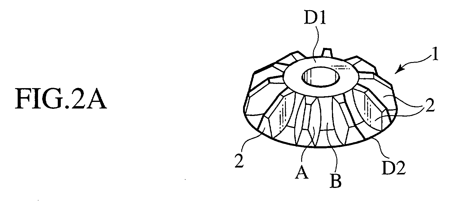
- the radius of curvature R2 of the fillet curve is set to be smaller than the maximum radius of curvature Rmax so as to constitute a maximum single radius of curvature connecting the bottom land B and the tooth flank A to provide a tooth-bottom shape suitable for a bevel gear, as shown in FIG. 2C.
- r1 denotes a radius of the small-diameter end D1
- r2 denotes a radius of the large-diameter end D2.
- the relationship between the radii of curvature R1, R2 and r1, r2 satisfies r1:r2 ⁇ R1:R2.
Landscapes
- Engineering & Computer Science (AREA)
- Mechanical Engineering (AREA)
- Physics & Mathematics (AREA)
- Thermal Sciences (AREA)
- General Engineering & Computer Science (AREA)
- Manufacturing & Machinery (AREA)
- Gears, Cams (AREA)
- Forging (AREA)
- Electrical Discharge Machining, Electrochemical Machining, And Combined Machining (AREA)
Abstract
Description
Claims (10)
- A bevel gear (1) comprising a plurality of teeth (2) each having a tooth flank (A), the tooth flank being connected with a bottom land (B) via a fillet curve having a radius of curvature (R), and a large-diameter end (D2) and a small-diameter end (D1), wherein the radius of curvature (R2) of the fillet curve at the large-diameter end is greater than the radius of curvature (R1) at the small-diameter end.
- A bevel gear (1) according to 1, wherein the radius of curvature (R1, R2) of the fillet curve between the tooth flank (A) and the bottom land (B) gradually increases from the small-diameter end (D1) to the large-diameter end (D2).
- A bevel gear (1) according to 1, wherein a maximum radius of curvature of the fillet curve is equal in value to the difference between a minimum meshing circle radius (rf) with respect to a mating gear (11) and a dedendum circle radius (rs).
- A bevel gear (1) according to 1, further comprising a web (W) provided at the outer edge of the bottom land (B), extending between the opposing tooth flanks (A).
- A bevel gear (1) according to 1, wherein:the small-diameter end (D1) is shaped to have two different radii of curvature; andthe large-diameter end (D2) is shaped to have a single radius of curvature.
- A bevel gear (1) according to 4, wherein a boundary portion (X) between the tooth flank (A) and the web (W) is shaped to have curvature with a radius of curvature equal to the radius of curvature (R2) of the large-diameter end (D2).
- A bevel gear (1) according to 1, wherein a boundary portion (Y) between the tooth flank (A) and an outer surface (E) of the tooth (2) is shaped to have a radius of curvature.
- A bevel gear (1) according to 1, prepared by a process comprising:preparing a forging die (31, 33) with a gear mold (32) in a reversed shape of the bevel gear; andforging the bevel gear with the forging die.
- A bevel gear (1) according to 8, prepared by a process further comprising:preparing an electrode for electric discharge machining (21) having a shape similar to that of the bevel gear; andproducing a forging die (31, 33) with a gear mold (32) in a reversed shape of the bevel gear, using the electrode.
- A bevel gear (1) according to 9, wherein the electrode for electric discharge machining (21) is provided with a cylinder (22) extending coaxially with a radius substantially identical to that of the large-diameter end (D2).
Applications Claiming Priority (2)
| Application Number | Priority Date | Filing Date | Title |
|---|---|---|---|
| JP2001098710 | 2001-03-30 | ||
| JP2001098710A JP3687556B2 (en) | 2001-03-30 | 2001-03-30 | Bevel gear and manufacturing method thereof |
Publications (4)
| Publication Number | Publication Date |
|---|---|
| EP1249641A2 true EP1249641A2 (en) | 2002-10-16 |
| EP1249641A3 EP1249641A3 (en) | 2002-10-23 |
| EP1249641B1 EP1249641B1 (en) | 2005-06-01 |
| EP1249641B2 EP1249641B2 (en) | 2009-01-07 |
Family
ID=18952337
Family Applications (1)
| Application Number | Title | Priority Date | Filing Date |
|---|---|---|---|
| EP02004886A Expired - Lifetime EP1249641B2 (en) | 2001-03-30 | 2002-03-04 | Bevel gear with modified fillet curve radius |
Country Status (4)
| Country | Link |
|---|---|
| US (1) | US6732605B2 (en) |
| EP (1) | EP1249641B2 (en) |
| JP (1) | JP3687556B2 (en) |
| DE (1) | DE60204382T3 (en) |
Cited By (2)
| Publication number | Priority date | Publication date | Assignee | Title |
|---|---|---|---|---|
| EP1538368A1 (en) * | 2003-12-02 | 2005-06-08 | Morse Tec Europe S.R.L. | Toothed rack for hydraulic chain tensioner |
| EP2584224A4 (en) * | 2010-06-21 | 2014-11-05 | O Oka Corp | GEAR WITH CURVED FREE SURFACES |
Families Citing this family (19)
| Publication number | Priority date | Publication date | Assignee | Title |
|---|---|---|---|---|
| DE10125067A1 (en) * | 2001-05-23 | 2002-12-12 | Bosch Gmbh Robert | crown |
| JP2003090413A (en) * | 2001-09-17 | 2003-03-28 | Gooshuu:Kk | Bevel gear having deformed roots and method of manufacturing the same |
| JP4189878B2 (en) * | 2002-06-21 | 2008-12-03 | トヨタ自動車株式会社 | Manufacturing method of bevel gear forging die |
| DE10235677B4 (en) * | 2002-08-03 | 2005-03-03 | Gkn Driveline International Gmbh | One-sided axial securing of gears in crown gear drives |
| US6981324B2 (en) * | 2003-03-26 | 2006-01-03 | American Axle & Manufacturing, Inc. | Method of manufacturing net-shaped gears for a differential assembly |
| US20050097977A1 (en) * | 2003-09-12 | 2005-05-12 | Van Cor Dale E. | Transmission systems |
| JP4907846B2 (en) * | 2004-03-12 | 2012-04-04 | 大岡技研株式会社 | Gear, gear manufacturing method and apparatus |
| JP4587853B2 (en) * | 2005-03-23 | 2010-11-24 | 株式会社エンプラス | Manufacturing method of molded gear |
| DE102005043124A1 (en) * | 2005-09-10 | 2007-03-15 | ThyssenKrupp Präzisionsschmiede GmbH | Bevel gear with connecting teeth |
| JP4895649B2 (en) * | 2006-03-20 | 2012-03-14 | アイシン精機株式会社 | Method for manufacturing member having face gear tooth surface |
| JP2008133873A (en) * | 2006-11-28 | 2008-06-12 | Aisin Seiki Co Ltd | Bent bevel gear with web |
| JP5005596B2 (en) | 2008-03-26 | 2012-08-22 | 株式会社エンプラス | Spiral bevel gear and gear device |
| JP5640814B2 (en) | 2011-02-24 | 2014-12-17 | アイシン・エィ・ダブリュ株式会社 | Tooth profile part manufacturing method and tooth profile part manufacturing apparatus |
| JP5609713B2 (en) * | 2011-02-24 | 2014-10-22 | アイシン・エィ・ダブリュ株式会社 | Tooth profile part manufacturing method and tooth profile part manufacturing apparatus |
| CN104653748A (en) * | 2014-11-20 | 2015-05-27 | 新誉集团有限公司 | S-shaped spiral bevel gear box |
| JP2018004053A (en) * | 2016-07-08 | 2018-01-11 | イスズモータースカンパニー(タイランド)リミテッド | Umbrella gear |
| JP6738020B2 (en) * | 2016-12-09 | 2020-08-12 | 豊田合成株式会社 | Electronic device |
| CN110864100B (en) * | 2019-10-25 | 2024-04-05 | 南京理工大学 | Bevel gear with tooth root variable radius transition fillet |
| DE102020113800A1 (en) | 2020-05-22 | 2021-11-25 | Hirschvogel Umformtechnik Gmbh | Gear with support structure |
Family Cites Families (8)
| Publication number | Priority date | Publication date | Assignee | Title |
|---|---|---|---|---|
| US2285575A (en) * | 1938-02-15 | 1942-06-09 | Frank V Elbertz | Bevel gear blank and the method and means for producing the same |
| US2436276A (en) * | 1940-12-31 | 1948-02-17 | Gleason Works | Variable leverage gearing |
| US2775922A (en) * | 1951-05-25 | 1957-01-01 | Gleason Works | Method and machine for making gears |
| US2778240A (en) * | 1953-03-18 | 1957-01-22 | Ocean City Mfg Company | Gear construction |
| JPS63215329A (en) * | 1987-03-05 | 1988-09-07 | Mitsubishi Metal Corp | Webbed bevel gear |
| JP3704811B2 (en) * | 1996-06-05 | 2005-10-12 | 日産自動車株式会社 | Tooth-shaped electrode for electric discharge machining and manufacturing method thereof |
| US6129793A (en) * | 1997-08-11 | 2000-10-10 | Tan; Jie | Face-gear forging method |
| US6324931B1 (en) * | 2000-04-19 | 2001-12-04 | Dana Corporation | Straight bevel gears with improved tooth root area geometry and method for manufacturing forging die for making thereof |
-
2001
- 2001-03-30 JP JP2001098710A patent/JP3687556B2/en not_active Expired - Fee Related
-
2002
- 2002-03-04 DE DE60204382T patent/DE60204382T3/en not_active Expired - Lifetime
- 2002-03-04 EP EP02004886A patent/EP1249641B2/en not_active Expired - Lifetime
- 2002-03-06 US US10/090,794 patent/US6732605B2/en not_active Expired - Lifetime
Cited By (3)
| Publication number | Priority date | Publication date | Assignee | Title |
|---|---|---|---|---|
| EP1538368A1 (en) * | 2003-12-02 | 2005-06-08 | Morse Tec Europe S.R.L. | Toothed rack for hydraulic chain tensioner |
| EP2584224A4 (en) * | 2010-06-21 | 2014-11-05 | O Oka Corp | GEAR WITH CURVED FREE SURFACES |
| US9091338B2 (en) | 2010-06-21 | 2015-07-28 | O-Oka Corporation | Free-form surface gear |
Also Published As
| Publication number | Publication date |
|---|---|
| DE60204382D1 (en) | 2005-07-07 |
| US20020148316A1 (en) | 2002-10-17 |
| JP3687556B2 (en) | 2005-08-24 |
| US6732605B2 (en) | 2004-05-11 |
| DE60204382T3 (en) | 2009-07-23 |
| EP1249641B2 (en) | 2009-01-07 |
| EP1249641A3 (en) | 2002-10-23 |
| DE60204382T2 (en) | 2005-10-13 |
| EP1249641B1 (en) | 2005-06-01 |
| JP2002295642A (en) | 2002-10-09 |
Similar Documents
| Publication | Publication Date | Title |
|---|---|---|
| US6732605B2 (en) | Bevel gear | |
| JP3155682U (en) | Gear for transmission | |
| KR101207884B1 (en) | Manufacturing method of gear | |
| WO2016197905A1 (en) | Gear-cutting hob and designing method therefor, and non-fully-symmetric involute gear and machining method therefor | |
| AU2004287509B2 (en) | Method and apparatus for forging gear teeth | |
| EP1110663B1 (en) | Method of manufacturing gear | |
| US6230578B1 (en) | Variable face width gearing | |
| JPH01199062A (en) | Forged gear for transmission | |
| CN115270324A (en) | Cold extrusion gear tooth root modeling method | |
| CN100414464C (en) | Modification method of involute straight bevel gear | |
| JP2005254307A (en) | Gear, method and apparatus for producing gear | |
| JPH08105513A (en) | High strength gears | |
| US20020170373A1 (en) | Variable face width gearing | |
| JP2001205385A (en) | Bevel gear with web for cold forging | |
| JP2013238299A (en) | Gear, gear device, and gear shaping tool | |
| JP2002028749A (en) | Link plate finishing method and link plate processed by the finishing method | |
| CN109931367B (en) | Linear bevel gear meshing structure, speed reducer and manufacturing method of linear bevel gear | |
| KR100429946B1 (en) | Method for Manufacturing Double Spur Gear in One Body by Cold Forging | |
| RU2066258C1 (en) | Method for manufacturing hollow internal parts | |
| CN116146688A (en) | A belt pulley internal gear and its processing method | |
| JP2004034050A (en) | Gear shaft and flat dies for rolling | |
| JP2006123148A (en) | Electric tool | |
| JPS61142015A (en) | Preparation of gear and gear cutting tool | |
| US20120040126A1 (en) | Blank of a Machine Component Comprising Teeth, and Method of Producing Such a Machine Component | |
| JPH08103846A (en) | Gear manufacturing method |
Legal Events
| Date | Code | Title | Description |
|---|---|---|---|
| PUAI | Public reference made under article 153(3) epc to a published international application that has entered the european phase |
Free format text: ORIGINAL CODE: 0009012 |
|
| PUAL | Search report despatched |
Free format text: ORIGINAL CODE: 0009013 |
|
| 17P | Request for examination filed |
Effective date: 20020304 |
|
| AK | Designated contracting states |
Kind code of ref document: A2 Designated state(s): AT BE CH CY DE DK ES FI FR GB GR IE IT LI LU MC NL PT SE TR |
|
| AX | Request for extension of the european patent |
Free format text: AL;LT;LV;MK;RO;SI |
|
| AK | Designated contracting states |
Kind code of ref document: A3 Designated state(s): AT BE CH CY DE DK ES FI FR GB GR IE IT LI LU MC NL PT SE TR |
|
| AX | Request for extension of the european patent |
Free format text: AL;LT;LV;MK;RO;SI |
|
| 17Q | First examination report despatched |
Effective date: 20030304 |
|
| AKX | Designation fees paid |
Designated state(s): DE FR GB |
|
| GRAP | Despatch of communication of intention to grant a patent |
Free format text: ORIGINAL CODE: EPIDOSNIGR1 |
|
| GRAS | Grant fee paid |
Free format text: ORIGINAL CODE: EPIDOSNIGR3 |
|
| GRAA | (expected) grant |
Free format text: ORIGINAL CODE: 0009210 |
|
| AK | Designated contracting states |
Kind code of ref document: B1 Designated state(s): DE FR GB |
|
| REG | Reference to a national code |
Ref country code: GB Ref legal event code: FG4D |
|
| REF | Corresponds to: |
Ref document number: 60204382 Country of ref document: DE Date of ref document: 20050707 Kind code of ref document: P |
|
| PLBI | Opposition filed |
Free format text: ORIGINAL CODE: 0009260 |
|
| PLAX | Notice of opposition and request to file observation + time limit sent |
Free format text: ORIGINAL CODE: EPIDOSNOBS2 |
|
| ET | Fr: translation filed | ||
| 26 | Opposition filed |
Opponent name: THYSSENKRUPP PRAEZISIONSSCHMIEDE GMBH Effective date: 20060223 |
|
| PLAF | Information modified related to communication of a notice of opposition and request to file observations + time limit |
Free format text: ORIGINAL CODE: EPIDOSCOBS2 |
|
| PLBB | Reply of patent proprietor to notice(s) of opposition received |
Free format text: ORIGINAL CODE: EPIDOSNOBS3 |
|
| PLAY | Examination report in opposition despatched + time limit |
Free format text: ORIGINAL CODE: EPIDOSNORE2 |
|
| PLBC | Reply to examination report in opposition received |
Free format text: ORIGINAL CODE: EPIDOSNORE3 |
|
| PUAH | Patent maintained in amended form |
Free format text: ORIGINAL CODE: 0009272 |
|
| STAA | Information on the status of an ep patent application or granted ep patent |
Free format text: STATUS: PATENT MAINTAINED AS AMENDED |
|
| 27A | Patent maintained in amended form |
Effective date: 20090107 |
|
| AK | Designated contracting states |
Kind code of ref document: B2 Designated state(s): DE FR GB |
|
| PGFP | Annual fee paid to national office [announced via postgrant information from national office to epo] |
Ref country code: GB Payment date: 20090304 Year of fee payment: 8 |
|
| PGFP | Annual fee paid to national office [announced via postgrant information from national office to epo] |
Ref country code: FR Payment date: 20090316 Year of fee payment: 8 |
|
| GBPC | Gb: european patent ceased through non-payment of renewal fee |
Effective date: 20100304 |
|
| PG25 | Lapsed in a contracting state [announced via postgrant information from national office to epo] |
Ref country code: GB Free format text: LAPSE BECAUSE OF NON-PAYMENT OF DUE FEES Effective date: 20100304 |
|
| REG | Reference to a national code |
Ref country code: FR Ref legal event code: ST Effective date: 20110722 |
|
| PG25 | Lapsed in a contracting state [announced via postgrant information from national office to epo] |
Ref country code: FR Free format text: LAPSE BECAUSE OF NON-PAYMENT OF DUE FEES Effective date: 20100331 |
|
| PGFP | Annual fee paid to national office [announced via postgrant information from national office to epo] |
Ref country code: DE Payment date: 20160302 Year of fee payment: 15 |
|
| REG | Reference to a national code |
Ref country code: DE Ref legal event code: R119 Ref document number: 60204382 Country of ref document: DE |
|
| PG25 | Lapsed in a contracting state [announced via postgrant information from national office to epo] |
Ref country code: DE Free format text: LAPSE BECAUSE OF NON-PAYMENT OF DUE FEES Effective date: 20171003 |