EP1249603B1 - Kompressoranlage und Verfahren zum Betreiben einer Kompressoranlage - Google Patents
Kompressoranlage und Verfahren zum Betreiben einer Kompressoranlage Download PDFInfo
- Publication number
- EP1249603B1 EP1249603B1 EP02006738A EP02006738A EP1249603B1 EP 1249603 B1 EP1249603 B1 EP 1249603B1 EP 02006738 A EP02006738 A EP 02006738A EP 02006738 A EP02006738 A EP 02006738A EP 1249603 B1 EP1249603 B1 EP 1249603B1
- Authority
- EP
- European Patent Office
- Prior art keywords
- compressor
- intercooler
- aftercooler
- cooling air
- compressed air
- Prior art date
- Legal status (The legal status is an assumption and is not a legal conclusion. Google has not performed a legal analysis and makes no representation as to the accuracy of the status listed.)
- Expired - Lifetime
Links
- 238000000034 method Methods 0.000 title description 2
- 238000001816 cooling Methods 0.000 claims abstract description 68
- 238000005192 partition Methods 0.000 claims description 13
- 238000004519 manufacturing process Methods 0.000 claims description 3
- 238000011144 upstream manufacturing Methods 0.000 claims description 3
- 239000003570 air Substances 0.000 description 120
- 230000007935 neutral effect Effects 0.000 description 9
- 230000001419 dependent effect Effects 0.000 description 7
- 230000033228 biological regulation Effects 0.000 description 6
- 230000003584 silencer Effects 0.000 description 5
- 230000001276 controlling effect Effects 0.000 description 4
- 238000013022 venting Methods 0.000 description 4
- 238000010586 diagram Methods 0.000 description 3
- 230000007704 transition Effects 0.000 description 3
- 230000006978 adaptation Effects 0.000 description 2
- XLYOFNOQVPJJNP-UHFFFAOYSA-N water Substances O XLYOFNOQVPJJNP-UHFFFAOYSA-N 0.000 description 2
- 239000012080 ambient air Substances 0.000 description 1
- 230000006835 compression Effects 0.000 description 1
- 238000007906 compression Methods 0.000 description 1
- 230000018044 dehydration Effects 0.000 description 1
- 238000006297 dehydration reaction Methods 0.000 description 1
- 230000003111 delayed effect Effects 0.000 description 1
- 230000001627 detrimental effect Effects 0.000 description 1
- 238000005265 energy consumption Methods 0.000 description 1
- 230000017525 heat dissipation Effects 0.000 description 1
- 238000010438 heat treatment Methods 0.000 description 1
- 238000005461 lubrication Methods 0.000 description 1
- 230000002265 prevention Effects 0.000 description 1
- 230000001105 regulatory effect Effects 0.000 description 1
- 229920006395 saturated elastomer Polymers 0.000 description 1
- 230000035939 shock Effects 0.000 description 1
Images



Classifications
-
- F—MECHANICAL ENGINEERING; LIGHTING; HEATING; WEAPONS; BLASTING
- F04—POSITIVE - DISPLACEMENT MACHINES FOR LIQUIDS; PUMPS FOR LIQUIDS OR ELASTIC FLUIDS
- F04C—ROTARY-PISTON, OR OSCILLATING-PISTON, POSITIVE-DISPLACEMENT MACHINES FOR LIQUIDS; ROTARY-PISTON, OR OSCILLATING-PISTON, POSITIVE-DISPLACEMENT PUMPS
- F04C28/00—Control of, monitoring of, or safety arrangements for, pumps or pumping installations specially adapted for elastic fluids
- F04C28/08—Control of, monitoring of, or safety arrangements for, pumps or pumping installations specially adapted for elastic fluids characterised by varying the rotational speed
-
- F—MECHANICAL ENGINEERING; LIGHTING; HEATING; WEAPONS; BLASTING
- F04—POSITIVE - DISPLACEMENT MACHINES FOR LIQUIDS; PUMPS FOR LIQUIDS OR ELASTIC FLUIDS
- F04B—POSITIVE-DISPLACEMENT MACHINES FOR LIQUIDS; PUMPS
- F04B25/00—Multi-stage pumps
-
- F—MECHANICAL ENGINEERING; LIGHTING; HEATING; WEAPONS; BLASTING
- F04—POSITIVE - DISPLACEMENT MACHINES FOR LIQUIDS; PUMPS FOR LIQUIDS OR ELASTIC FLUIDS
- F04B—POSITIVE-DISPLACEMENT MACHINES FOR LIQUIDS; PUMPS
- F04B41/00—Pumping installations or systems specially adapted for elastic fluids
-
- F—MECHANICAL ENGINEERING; LIGHTING; HEATING; WEAPONS; BLASTING
- F04—POSITIVE - DISPLACEMENT MACHINES FOR LIQUIDS; PUMPS FOR LIQUIDS OR ELASTIC FLUIDS
- F04C—ROTARY-PISTON, OR OSCILLATING-PISTON, POSITIVE-DISPLACEMENT MACHINES FOR LIQUIDS; ROTARY-PISTON, OR OSCILLATING-PISTON, POSITIVE-DISPLACEMENT PUMPS
- F04C23/00—Combinations of two or more pumps, each being of rotary-piston or oscillating-piston type, specially adapted for elastic fluids; Pumping installations specially adapted for elastic fluids; Multi-stage pumps specially adapted for elastic fluids
-
- F—MECHANICAL ENGINEERING; LIGHTING; HEATING; WEAPONS; BLASTING
- F04—POSITIVE - DISPLACEMENT MACHINES FOR LIQUIDS; PUMPS FOR LIQUIDS OR ELASTIC FLUIDS
- F04C—ROTARY-PISTON, OR OSCILLATING-PISTON, POSITIVE-DISPLACEMENT MACHINES FOR LIQUIDS; ROTARY-PISTON, OR OSCILLATING-PISTON, POSITIVE-DISPLACEMENT PUMPS
- F04C29/00—Component parts, details or accessories of pumps or pumping installations, not provided for in groups F04C18/00 - F04C28/00
- F04C29/04—Heating; Cooling; Heat insulation
Definitions
- the invention relates to a compressor system for the generation of compressed air, with at least two compressor stages - a first compressor stage and a last compressor stage - and with an intercooler for compressed air following the first compressor stage, and optionally with an aftercooler for the compressed air following the last Compressor stage, wherein the intercooler and the optionally provided aftercooler are acted upon by fans with cooling air, and wherein the amount of cooling air for the intercooler is changeable.
- the invention relates to a compressor system with at least one compressor stage and an aftercooler for the compressed air, wherein the aftercooler is acted upon by a fan with cooling air, and wherein the amount of cooling air for the aftercooler is changeable.
- the compressed air In the generation of compressed air by compressors accumulates a large amount of dissipated heat. The generated compressed air must not exceed a defined temperature level for safety reasons.
- the compressed air is passed through an aftercooler and thereby cooled. For this purpose, the aftercooler is acted upon by a fan with cooling air.
- an intercooler is arranged in each case between two compressor stages, which is also acted upon by a fan with cooling air. Accordingly, an intercooler is provided in two-stage compressors.
- a fan for the radiator is electrically powered and turned on as soon as the compressor stages run.
- the compressed air entering the next compressor stage should not contain any condensed water. Otherwise, the service life of the following compressor stage is greatly reduced.
- the intercooler is designed so that the exiting compressed air has a temperature several degrees above the dew point.
- a condensate separator may be provided.
- the dew point also changes. Consequently, the amount of cooling air and intercooler are designed for the highest conceivable dew point temperature. In individual cases, therefore, a large temperature difference between the outlet temperature of the compressed air at the intercooler and the currently existing dew point occur.
- the compressors change to supply an adequate amount of compressed air at least between full load and idle.
- a stoppage of the compressor rotor can be additionally provided.
- the cooling air supplying fans are active, and usually to the same extent as at full load.
- intercooler and aftercooler are cooled much more strongly in idling operation of the compressor than in full load operation. There are sudden temperature jumps that put extreme strain on the mechanical strength of the radiators.
- JP 11 037 053 shows a compressor system with two stages, coolers and fans, wherein the fans are driven by the shaft of the respective compressor. Accordingly, the fans rotate in proportion to the compressor speed and provide a dependent, varying amount of cooling air. Not recognizable is an adaptation of the cooling air quantity with speed-independent load change.
- a similarly working compressor system is also shown in JP 10 184 571.
- the compressor system according to the invention is characterized by means for controlling the amount of cooling air for the intercooler, such that the amount of cooling air - to avoid temperature jumps in the intercooler - adaptable to a changing load or power of the compressor stage and in particular during idling operation of the compressor stage is reducible.
- the amount of cooling air in dependence on the Temperature of the emerging from the intercooler compressed air and / or the current dew point temperature is adjustable.
- the temperature of the compressed air generated by the compressor is cooled down as much as possible in the intercooler, but remains above the current dew point, in particular about 5 ° C above the pressure dew point.
- the pressure dew point in each case depends on the temperature and relative humidity of the ambient air sucked in by the first compressor stage.
- the means may be provided such that the amount of cooling air for the intercooler depending on the power of the first compressor stage, in particular in the idle mode of the compressor is reduced and thus temperature jumps are avoided in the intercooler.
- the amount of cooling air is also adaptable to a changing load of the compressor. Screw compressors, in particular, are operated variably in the load range from 40% to 100% of the full load and depending on the compressed air requirement. It is expedient to adapt the amount of cooling air to the amount of compressed air varying in this case, also in combination with a dependence of the amount of cooling air on the current dew point temperature.
- an electric drive for the fan of the intercooler is adjustable.
- the control of the drive takes place as a function of the current dew point temperature and / or of the current compressor load or compressed air quantity.
- Simple control is possible by pole changing an electric motor as a drive for the fan, as soon as the compressor between the load conditions full load and idle changes.
- Variable also with regard to a load-dependent control, is a frequency control of the electric motor for the fan.
- control means for diverting at least a part of the cooling air provided for the intercooler are arranged.
- control flaps are provided in front of the fan or the intercooler. The moving cooling air is wholly or partially diverted before the intercooler, so that the latter is no longer or only partially acted upon with cooling air.
- intercooler and aftercooler are supplied with cooling air via separate, separate fans.
- the heat budgets of the fans can then be controlled independently of each other.
- a partition is preferably arranged between the intercooler and the aftercooler, so that a mutual thermal influence is excluded. With several intermediate coolers (for several compressor stages), it is also possible to arrange between these partitions.
- means are provided for regulating the amount of cooling air for the aftercooler.
- the goal here is a scheme for adjusting the outlet temperature to the optimum inlet temperature of the subsequent devices during the air promotion.
- the compressed air is dried after leaving the compressor (aftercooler).
- a dryer is designed for a certain inlet temperature range, in particular for about 160 ° to 200 ° C. In practice occurring deviations of the current compressed air temperature from the calculated dryer inlet temperature or fluctuations of the current ambient temperature lead to efficiency losses.
- the inventively provided means for controlling the amount of cooling air prevent such losses.
- the cooling air volume control can be used to achieve an energy-saving operation of the cooling air power requirement within the specified inlet temperature range of the following devices. This applies to the operation of the compressor system with delayed intermittent operation, full load idle operation and in particular for a speed control of the compressor system.
- regulation of the fan drive and / or diversion of at least part of the cooling air can also be provided for the aftercooler.
- the control of the amount of cooling air for the aftercooler can be provided independently of the existence of an intercooler, for example, when the compressor has only one compressor stage.
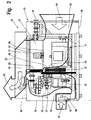
- a compressor unit 10 has two screw compressors as compressor stages 11, 12. Surrounding the compressor stages of a housing 13 which is formed heat and sound insulating, has different openings for the entry of fresh air or cooling air, the outlet of a compressed air line and hot air and in addition various auxiliary units are arranged.
- the compressor stages 11, 12 are driven by an electric main drive motor 14. This is coupled to the compressor stages via a belt drive 15.
- the fresh air enters via a suction muffler 16 in the housing 13 and is fed to a part of a suction filter 17 and passed to the other part via the compressor stages 11, 12 as cooling air.
- the associated air streams are outlined in bold in FIGS. 1 and 2. Visible are a total of three air streams, namely the fresh air 18, which is compressed in the compressor stages 11,12 to compressed air, the cooling air 19, which is passed outside the compressor stages 11, 12, and the cooling air 20, which passes the main drive motor 14 and in parallel via an intercooler (first radiator) 21 and an aftercooler (last radiator) 22 is passed.
- the two cooling air streams 19, 20 are combined after heating to an exhaust air stream 23.
- the fresh air stream 18 and the cooling air stream 19 enter the housing 13 as a common air flow via the intake silencer 16 and only then split up there in accordance with the prevailing pressure and temperature conditions.
- the compressed air generated in the compressor stages exits via a pipe 24 from the housing 13.
- the mentioned components of the compressor system 10 are arranged in the housing 13 in a special way to achieve the best possible thermal conditions:
- the housing 13 is subdivided by an upright partition 25 into a compressor chamber 26 and a cooler chamber 27.
- the housing 13 itself is substantially rectangular with bottom wall 28, large side walls 29, 30, smaller end walls 31, 32 and top wall 33.
- the partition 25 runs parallel to the end walls 31, 32 and creates in the housing 13 about a division of 1/3 to 2/3, wherein the radiator chamber 27 is almost twice as large as the compressor chamber 26th
- the partition 25 extends from the bottom wall 28 not over the entire height of the housing 13. Rather, an upper part of the housing 13 forms an exhaust chamber 34, which is bounded below the cooler space 27 by the side by side (parallel) radiator 21, 22, optionally additionally by an oil cooler 35. Between the compressor chamber 26 and the exhaust chamber 34, a transition is also provided, namely a narrow exhaust air inlet 36, also referred to as an ejector. The heated cooling air flow 19 enters the exhaust air chamber 34 via the exhaust air inlet 36.
- the two compressor stages 11, 12, the intake muffler 16, the suction filter 17, a suction regulator 37 and unspecified pipes are arranged.
- the main drive motor 14 the belt drive 15, two fans 38, 39 with their electric drive motors 40, 41 for the two coolers 21, 22 and the latter, optionally additionally the oil cooler 35.
- the compressed air-carrying pipeline 24 preferably runs through the Radiator 27.
- a drive shaft 42 of the first compressor stage 11 extends through the partition wall 25, so that a drive pulley 43 is already arranged in the radiator chamber 27.
- the partition 25 is formed thermally insulating. Temperature changes on one side of the partition 25 thus do not or only very hesitantly affect the temperature level on the other side of the partition.
- Fig. 3 gives an overview of the order of different aggregates in the production of compressed air and control technical dependencies of individual units.
- the stream of compressed air is shown in bold, oil lines, electrical lines - including signal lines - in contrast, only with a simple line thickness.
- Also not shown in bold are mechanical connections, such as the main drive motor 14 to the two compressor stages 11, 12th
- the compressed air generated is stored in a compressed air tank 44 outside the housing 13 and fed from there into a compressed air network, not shown.
- a pressure sensor 45 reports the prevailing pressure in the compressed air tank 44 to a control unit 46.
- This has the function of a compressor control to provide a sufficient amount of compressed air.
- Such pressure-dependent controls for switching on and off the drive of compressor stages 11, 12 are known in principle.
- the control unit 46 has additional tasks to fulfill as a function of certain measured variables. Outside of the housing 13, for example, in front of the compressed air tank 44 (as shown here) or after the same a compressed air dryer 47 is provided. Here, the moisture present in the compressed air and the condensate are eliminated.
- the efficiency of the compressed air dryer is highly dependent on the inlet temperature of the ambient temperature, the volume flow and the operating pressure.
- For detecting the inlet temperature of the compressed air dryer 47 is preceded by a temperature sensor 48.
- the actual value detected here is also supplied to the control unit 46.
- Corresponding sensors 49, 50, 51 are arranged upstream of the suction filter 17 and may for example be provided on the outside of the housing 13. These sensors also supply their measured values to the control unit 46.
- the drive motors 40, 41 for the fans 38, 39 of the two coolers 21, 22 are controlled by the control unit 46.
- the control unit responds only in dependence on the pressure values on the sensor 45. After falling below a minimum, the drive motor 14 starts and runs at 100% power. In synchronism with this, the drive motors 40, 41 for the fans of the coolers 21, 22 run. After reaching a maximum pressure, the control unit 46 switches the main drive motor 14 back to about 30% of the power, so that the two compressor stages 11, 12 operate at idle and no more compressed air is generated (idle control). The drive motors 40, 41 continue to run with unchanged power. Intercooler 21 and aftercooler 22 cool off abruptly.
- the speed of the compressor stages is adapted to the current compressed air requirement. At less than 50% of full power, the compressor stages are generally uneconomical. It is better then a transition to idle mode. Even with this scheme, the motors 40, 41 for the fans of the radiator 21, 22 but always work at full power, provided that Compressor stages 11, 12 are driven at all. At partial load speed and idling cool the radiator 21, 22 therefore strong.
- the compressor stages 11, 12 are driven analogously to 1. and 2. between full load and idle or between full load, part load and idle. Analogous to the load, the electric power of the motors 40, 41 for the fans of the radiators 21, 22 is varied, so that the temperatures of the radiator 21, 22 remain largely stable even at idle or in partial load operation and larger temperature gradients are avoided.
- the compressed air emerging from the last cooler of a compressor unit, in this case from the aftercooler 22, is saturated with water vapor and is usually dried in the downstream dryer 47.
- the latter is designed for a certain inlet temperature range of the compressed air and has its best efficiency and lowest energy consumption when maintaining this temperature range.
- the motor 41 for the radiator 22 is controlled by the control unit 46 in dependence on the compressed air temperature so that the dryer 47 can operate in its optimum range. For this purpose, the temperature is taken at the sensor 48 before entering the dryer 47 and processed by the control unit 46 for controlling the motor 41.
- the overall efficiency of compressed air production improves with the cooling of the compressed air between the compressor stages.
- a reduced cooling to maintain the said "safety distance" to the dew point thus reduces the overall efficiency.
- the climatic conditions at the place of use are permanently recorded and taken into account in the control of cooling.
- the sensors 49, 50, 51 for example, on the outside of the housing 13, provide current pressure, temperature and humidity values to the control unit 46. From this, the values for the compressed air before entry into the control unit 46 can be determined on the basis of empirical values and corresponding characteristic curves Determine intercooler 21. In the same, the compressed air is cooled down as close as possible to the dew point, without falling below this. In the control unit 46, a calculation of the dew point and the determination and provision of the electric power of the motor 40 for the fan of the intercooler 21.
- cooling air ducts may also be provided, which are variable as a function of the parameters mentioned, such as cooling air flaps, not shown, for diverting the cooling air otherwise impinging on the radiators 21, 22.
- the fans can continue to run in this version without any change in performance. Instead, the cooling air is wholly or partially deflected around the radiator or led out of the housing 13 elsewhere.
- the control flaps provided for this purpose are in particular suitably driven electrically in a suitable manner.
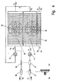
- the fans 38, 39 are arranged so that only the respectively associated radiator 21, 22 acted upon becomes. Also, a thermally insulated (right) partition 52 is disposed between the coolers 21, 22.
- the oil cooler 35 can - as in Fig. 1 - arranged in the plane of the intercooler 21 and be acted upon by the fan 38.
- the oil cooler is arranged elsewhere, for example after entry of the cooling air flow 20 into the cooler chamber 27, in particular following an intake silencer 53.
- a separate fan 58 may be provided.
- a temperature sensor 54 is disposed downstream of the intercooler 21 and upstream of the second or last compressor stage 12. The measured temperature value is - as well as the values measured by the other sensors 48-51 - evaluated by the control unit 46 for controlling the drive motors 40, 41 and possibly the engine for the oil cooler 35 and 57, respectively.
- the compressor stages are designed in the present case as air-cooled oil-free screw compressors or just such turbocompressors, the heat output of the oil cooler 35 is relatively low. Only the oil used in the compressor stages for the lubrication of bearings and gears is cooled.
- FIGS. 4 and 5 illustrate the temperatures and volume flows occurring during full-load operation (FIG. 4) on the one hand and idling operation (FIG. 5) on the other.
- the associated numerical values can be taken from the table provided at the end of the description.
- the temperatures of the compressed air are detected at different locations of the compressor system, namely the temperature T1 of the compressed air following the first compressor 11 and before entering the intercooler 21, the temperature T2 after the exit of the compressed air from the intercooler 21, the temperature T3 in the connection to the second compressor 12 and before entering the aftercooler 22, the temperature T4 after discharge of the compressed air from the aftercooler 22 and the temperature T5 between the second compressor 12 and a vent valve 55.
- the latter is connected to a venting silencer 56 for delivering the excess compressed air ,
- the compressed air in the intercooler 21 should only be cooled to a temperature above the pressure dew point.
- the temperatures T2 in Figs. 4 and 5 (45 ° C and 40 ° C) are each above the pressure dew point to be considered at this point.
- the temperature T3 of the compressed air entering the aftercooler 22 at full load is approximately 250.degree.
- the fans 38, 39 turn off or are downshifted to low speeds.
- the aftercooler 22 no hot compressed air flows. Accordingly, the aftercooler 22 cools relatively slowly, starting from 250 ° C.
- the temperature T4 (30 ° C) is reached only after a longer idling time. In practice, before run the compressor 11, 12 again.
- a volumetric flow V2 following the venting muffler 56 changes accordingly between 0% (full load) and 10 - 15% (idling).
- a volume flow V3 entering the aftercooler 22 at idling is 0%.
- V T V place operating condition V1 100% in front of the suction filter 17 full load
- V2 0%
- V1 10-15% in front of the suction filter 17
- Neutral V2 10-15%
Landscapes
- Engineering & Computer Science (AREA)
- Mechanical Engineering (AREA)
- General Engineering & Computer Science (AREA)
- Compressor (AREA)
- Control Of Positive-Displacement Pumps (AREA)
- Compressors, Vaccum Pumps And Other Relevant Systems (AREA)
- Control Of Multiple Motors (AREA)
- Applications Or Details Of Rotary Compressors (AREA)
Description
- Die Erfindung betrifft eine Kompressoranlage für die Erzeugung von Druckluft, mit mindestens zwei Verdichterstufen - einer ersten Verdichterstufe und einer letzten Verdichterstufe - und mit einem Zwischenkühler für Druckluft im Anschluss an die erste Verdichterstufe, und wahlweise mit einem Nachkühler für die Druckluft im Anschluss an die letzte Verdichterstufe, wobei der Zwischenkühler und der wahlweise vorgesehene Nachkühler durch Lüfter mit Kühlluft beaufschlagt werden, und wobei die Kühlluftmenge für den Zwischenkühler veränderbar ist. Daneben betrifft die Erfindung eine Kompressoranlage mit mindestens einer Verdichterstufe und einem Nachkühler für die Druckluft, wobei der Nachkühler durch einen Lüfter mit Kühlluft beaufschlagt wird, und wobei die Kühlluftmenge für den Nachkühler veränderbar ist.
- Bei der Erzeugung von Druckluft durch Kompressoren fällt eine große Menge abzuführender Wärme an. Die erzeugte Druckluft darf ein definiertes Temperaturniveau schon aus Sicherheitsgründen nicht überschreiten. In bestimmten Anwendungsfällen wird die Druckluft durch einen Nachkühler geführt und dabei abgekühlt. Hierzu wird der Nachkühler über einen Lüfter mit Kühlluft beaufschlagt.
- Besonders relevant ist die gezielte Wärmeabfuhr bei mehrstufigen Kompressoren, etwa luftgekühlten, ölfreien Schraubenkompressoren, Kolbenkompressoren und Turbokompressoren. Zur Verbesserung des Wirkungsgrades ist jeweils zwischen zwei Verdichterstufen ein Zwischenkühler angeordnet, der ebenfalls durch einen Lüfter mit Kühlluft beaufschlagt wird. Entsprechend ist bei zweistufigen Kompressoren ein Zwischenkühler vorgesehen. Üblicherweise wird ein Lüfter für die Kühler elektrisch angetrieben und eingeschaltet, sobald auch die Verdichterstufen laufen.
- Die in die jeweils nächste Verdichterstufe eintretende Druckluft soll kein kondensiertes Wasser enthalten. Anderenfalls wird die Lebensdauer der folgenden Verdichterstufe stark verkürzt. Der Zwischenkühler ist so ausgelegt, dass die austretende Druckluft eine Temperatur mehrere Grad über dem Taupunkt aufweist. Alternativ oder zusätzlich kann ein Kondensatabscheider vorgesehen sein.
- In Abhängigkeit von den äußeren klimatischen Bedingungen ändert sich auch der Taupunkt. Folglich sind Kühlluftmenge und Zwischenkühler für die höchste denkbare Taupunkttemperatur ausgelegt. Im Einzelfall kann deshalb ein großer Temperaturabstand zwischen der Austrittstemperatur der Druckluft am Zwischenkühler und dem gerade bestehenden Taupunkt auftreten.
- Bei Verwendung mehrerer Verdichterstufen ist eine Kühlung der Druckluft zwischen den Verdichterstufen für die Verbesserung des Wirkungsgrades von großer Bedeutung. Die Druckluft sollte im Zwischenkühler soweit wie möglich abgekühlt werden. Ein großer Temperaturabstand zwischen dem Taupunkt und der Temperatur der aus dem Zwischenkühler austretenden Druckluft ist somit für den Wirkungsgrad des Kompressors nachteilig.
- Die Kompressoren wechseln zur Lieferung einer bedarfsgerechten Druckluftmenge zumindest zwischen Volllast und Leerlauf. Ein Stillstand der Kompressorläufer kann zusätzlich vorgesehen sein. Im Leerlaufbetrieb sind auch die Kühlluft liefernden Lüfter aktiv und zwar üblicherweise in demselben Maße wie bei Volllast. Entsprechend werden Zwischenkühler und Nachkühler im Leerlaufbetrieb des Kompressors wesentlich stärker abgekühlt als im Volllastbetrieb. Es treten plötzliche Temperatursprünge auf, die die mechanische Festigkeit der Kühler extrem belasten.
- Die JP 11 037 053 zeigt eine Kompressoranlage mit zwei Stufen, Kühlern und Lüftern, wobei die Lüfter von der Welle des jeweiligen Verdichters mit angetrieben sind. Entsprechend drehen die Lüfter proportional zur Verdichterdrehzahl und liefern eine hiervon abhängige, sich ändernde Kühlluftmenge. Nicht erkennbar ist eine Anpassung der Kühlluftmenge bei Drehzahl- unabhängiger Laständerung. Eine ähnlich arbeitende Kompressoranlage zeigt auch die JP 10 184 571.
- Die DE 199 33 989 A1 zeigt eine zweistufige Kompressoranlage mit Zwischenkühler und Nachkühler. Im Zwischenkühler wird der verdichtete Gasstrom auf seine Temperatur beim Eintritt in die erste Verdichterstufe zurückgekühlt, ebenso im Nachkühler. Eine Regelung zur Vermeidung von Temperatursprüngen ist nicht erkennbar.
- Zur Vermeidung der genannten Nachteile ist die erfindungsgemäße Kompressoranlage gekennzeichnet durch Mittel zum Regeln der Kühlluftmenge für den Zwischenkühler, derart, dass die Kühlluftmenge - zur Vermeidung von Temperatursprüngen im Zwischenkühler - an eine sich ändernde Last bzw. Leistung der Verdichterstufe anpassbar und insbesondere im Leerlaufbetrieb der Verdichterstufe reduzierbar ist. Insbesondere handelt es sich um Mittel, mit denen die Kühlluftmenge in Abhängigkeit von der Temperatur der aus dem Zwischenkühler austretenden Druckluft und/oder der aktuellen Taupunkttemperatur regelbar ist. Die Temperatur der vom Kompressor erzeugten Druckluft wird im Zwischenkühler soweit wie möglich herabgekühlt, bleibt jedoch oberhalb des aktuellen Drucktaupunkts, insbesondere etwa 5°C über dem Drucktaupunkt. Der Drucktaupunkt hängt jeweils von der Temperatur und relativen Luftfeuchtigkeit der von der ersten Verdichterstufe angesaugten Umgebungsluft ab.
- Alternativ oder zusätzlich können die Mittel derart vorgesehen sein, dass die Kühlluftmenge für den Zwischenkühler in Abhängigkeit von der Leistung der ersten Verdichterstufe, insbesondere im Leerlaufbetrieb des Kompressors reduzierbar ist und damit Temperatursprünge im Zwischenkühler vermieden werden. Vorteilhafterweise ist die Kühlluftmenge auch an eine sich ändernde Last des Kompressors anpassbar. Insbesondere Schraubenkompressoren werden im Lastbereich von 40% bis 100% der Volllast variabel und abhängig vom Druckluftbedarf gefahren. Zweckmäßig ist eine Anpassung der Kühlluftmenge an die in diesem Fall variierende Druckluftmenge, auch in Kombination mit einer Abhängigkeit der Kühlluftmenge von der aktuellen Taupunkttemperatur.
- Nach einem weiteren Gedanken der Erfindung ist ein elektrischer Antrieb für den Lüfter des Zwischenkühlers regelbar. Wie zuvor dargestellt, erfolgt die Regelung des Antriebs in Abhängigkeit von der aktuellen Taupunkttemperatur und/oder von der aktuellen Kompressorlast bzw. Druckluftmenge.
- Eine einfache Regelung ist möglich durch Polumschaltung eines Elektromotors als Antrieb für den Lüfter, sobald der Kompressor zwischen den Lastzuständen Volllast und Leerlauf wechselt. Variabler, auch im Hinblick auf eine lastabhängige Regelung, ist eine Frequenzregelung des Elektromotors für den Lüfter.
- Alternativ oder zusätzlich sind Steuerorgane zum Umleiten zumindest eines Teils der für den Zwischenkühler vorgesehenen Kühlluft angeordnet. Insbesondere sind Steuerklappen vor dem Lüfter oder dem Zwischenkühler vorgesehen. Die bewegte Kühlluft wird ganz oder teilweise vor dem Zwischenkühler abgezweigt, so dass letzterer nicht mehr oder nur teilweise mit Kühlluft beaufschlagt wird.
- Vorteilhafterweise werden Zwischenkühler und Nachkühler über separate, jeweils eigene Lüfter mit Kühlluft beaufschlagt. Die Wärmehaushalte der Lüfter können dann unabhängig voneinander geregelt werden. Auch ist vorzugsweise zwischen dem Zwischenkühler und dem Nachkühler eine Trennwand angeordnet, so dass eine gegenseitige thermische Beeinflussung ausgeschlossen ist. Bei mehreren Zwischenkühlem (für mehrere Verdichterstufen) können auch zwischen diesen Trennwände angeordnet sein.
- In Fortbildung der Erfindung sind Mittel zum Regeln der Kühlluftmenge für den Nachkühler vorgesehen. Neben der Verhinderung von Temperaturschocks beim Umschalten, insbesondere von Volllast in Leerlauf und für eine Liefermengenregelung des Kompressors, z.B. durch Frequenzregelung des Hauptantriebmotors, ist darüber hinaus das Ziel hier eine Regelung zur Anpassung der Austrittstemperatur an die optimale Eintrittstemperatur der nachfolgenden Geräte während der Luftförderung. Üblicherweise wird die Druckluft nach dem Austritt aus dem Kompressor (Nachkühler) getrocknet. Ein Trockner ist für einen bestimmten Eintrittstemperaturbereich ausgelegt, insbesondere für etwa 160° bis 200°C. In der Praxis auftretende Abweichungen der aktuellen Drucklufttemperatur von der berechneten Trockner-Eintrittstemperatur bzw. Schwankungen der aktuellen Umgebungstemperatur führen zu Wirkungsgradverlusten. Die erfindungsgemäß vorgesehenen Mittel zum Regeln der Kühlluftmenge verhindern derartige Verluste.
- Durch die Kühlluftmengenregelung lässt sich ein energiesparender Betrieb des Kühlluftleistungsbedarfs in den vorgegebenen Eintrittstemperaturbereich der nachfolgenden Geräte erzielen. Das gilt für den Betrieb der Kompressoranlage mit verzögertem Aussetzbetrieb, Volllast-Leerlaufbetrieb und insbesondere für eine Drehzahlregelung der Kompressoranlage.
- Generell ergibt sich durch die jeweils geregelte Drehzahl der Kühlluftventilatoren (Lüfter) eine höhere Wirtschaftlichkeit und wesentlich reduzierte Geräuschentwicklung der Kompressoranlage bei Teillastbetrieb und im Leerlauf.
- Entsprechend den voranstehenden Ausführungen zum Zwischenkühler können auch für den Nachkühler eine Regelung des Lüfterantriebs und/oder eine Umleitung zumindest eines Teils der Kühlluft vorgesehen sein.
- Die Regelung der Kühlluftmenge für den Nachkühler kann unabhängig von der Existenz eines Zwischenkühlers vorgesehen sein, beispielsweise dann, wenn der Kompressor nur eine Verdichterstufe aufweist.
- Weitere Ausführungsformen der Erfindung - auch das erfindungsgemäße Verfahren - ergeben sich aus der Beschreibung und aus den Patentansprüchen. Vorteilhafte Ausführungsformen werden nachfolgend anhand von Zeichnungen näher beschrieben. Es zeigen:
- Fig. 1
- eine Kompressoranlage mit zwei Verdichterstufen, jeweils als ölfreie, luftgekühlte Schraubenkompressoren ausgeführt,
- Fig. 2
- eine Seitenansicht der Kompressoranlage gem. Fig.1,
- Fig. 3
- ein Diagramm mit auseinandergezogener Darstellung der Komponenten einer Kompressoranlage mit zwei Verdichterstufen,
- Fig. 4
- ein Diagramm zur Darstellung der Volumenströme und Temperaturen im Volllastbetrieb,
- Fig. 5
- ein Diagramm zur Darstellung der Volumenströme und Temperaturen im Leerlaufbetrieb.
- Eine Kompressoranlage 10 weist als Verdichterstufen 11, 12 zwei Schraubenkompressoren auf. Umgeben sind die Verdichterstufen von einem Gehäuse 13, das wärme- und schalldämmend ausgebildet ist, verschiedene Öffnungen zum Eintritt von Frischluft bzw. Kühlluft, zum Austritt einer Druckluftleitung und von Warmluft aufweist und in dem zusätzlich verschiedene Nebenaggregate angeordnet sind.
- Die Verdichterstufen 11, 12 werden angetrieben von einem elektrischen Hauptantriebsmotor 14. Dieser ist mit den Verdichterstufen über einen Riementrieb 15 gekoppelt.
- Die Frischluft tritt über einen Ansaugschalldämpfer 16 in das Gehäuse 13 ein und wird zu einem Teil einem Ansaugfilter 17 zugeführt und zum anderen Teil über die Verdichterstufen 11, 12 als Kühlluft geleitet. Die zugehörigen Luftströme sind in den Fig. 1 und 2 fett umrandet. Erkennbar sind insgesamt drei Luftströme, nämlich die Frischluft 18, die in den Verdichterstufen 11,12 zu Druckluft komprimiert wird, die Kühlluft 19, die außen an den Verdichterstufen 11, 12 vorbeigeleitet wird, und die Kühlluft 20, die den Hauptantriebsmotor 14 passiert und parallel über einen Zwischenkühler (erster Kühler) 21 und einen Nachkühler (letzter Kühler) 22 geleitet wird.
- Die beiden Kühlluftströme 19, 20 werden nach Erwärmung zu einem Abluftstrom 23 zusammengeführt. Der Frischluftstrom 18 und der Kühlluftstrom 19 treten als ein gemeinsamer Luftstrom über den Ansaugschalldämpfer 16 in das Gehäuse 13 ein und teilen sich erst dort entsprechend den vorliegenden Druck- und Temperaturverhältnissen auf.
- Die in den Verdichterstufen erzeugte Druckluft tritt über eine Rohrleitung 24 aus dem Gehäuse 13 aus.
- Die genannten Bauteile der Kompressoranlage 10 sind im Gehäuse 13 in besonderer Weise zur Erzielung bestmöglicher thermischer Bedingungen angeordnet:
- Das Gehäuse 13 ist durch eine aufrechte Trennwand 25 unterteilt in einen Kompressorraum 26 und einen Kühlerraum 27. Das Gehäuse 13 ist selbst im Wesentlichen rechtekkig gestaltet mit Bodenwand 28, großen Seitenwänden 29, 30, kleineren Stirnwänden 31, 32 und Oberwand 33. Die Trennwand 25 verläuft parallel zu den Stirnwänden 31, 32 und schafft im Gehäuse 13 etwa eine Aufteilung von 1/3 zu 2/3, wobei der Kühlerraum 27 nahezu doppelt so groß ist wie der Kompressorraum 26.
- Die Trennwand 25 reicht von der Bodenwand 28 nicht über die gesamte Höhe des Gehäuses 13. Vielmehr bildet ein oberer Teil des Gehäuses 13 eine Abluftkammer 34, die nach unten gegenüber dem Kühlerraum 27 begrenzt ist durch die nebeneinander angeordneten (parallelen) Kühler 21, 22, gegebenenfalls zusätzlich noch durch einen Ölkühler 35. Zwischen dem Kompressorraum 26 und der Abluftkammer 34 ist ebenfalls ein Übergang vorgesehen, nämlich ein schmaler Ablufteinlass 36, auch als Ejektor bezeichnet. Der erwärmte Kühlluftstrom 19 tritt über den Ablufteinlass 36 in die Abluftkammer 34 ein.
- Im Kompressorraum 26 sind die beiden Verdichterstufen 11, 12, der Ansaugschalldämpfer 16, der Ansaugfilter 17, ein Ansaugregler 37 und nicht näher bezeichnete Rohrleitungen angeordnet. Im Kühlerraum 27 vorgesehen sind der Hauptantriebsmotor 14, der Riementrieb 15, zwei Lüfter 38, 39 mit ihren elektrischen Antriebsmotoren 40, 41 für die beiden Kühler 21, 22 sowie letztere, gegebenenfalls zusätzlich noch der Ölkühler 35. Die druckluftführende Rohrleitung 24 läuft vorzugsweise durch den Kühlerraum 27. Eine Antriebswelle 42 der ersten Verdichterstufe 11 erstreckt sich durch die Trennwand 25 hindurch, sodass eine Antriebsriemenscheibe 43 bereits im Kühlerraum 27 angeordnet ist.
- Die Trennwand 25 ist wärmedämmend ausgebildet. Temperaturänderungen auf einer Seite der Trennwand 25 beeinflussen somit nicht oder nur sehr zögerlich das Temperatumiveau auf der jeweils anderen Seite der Trennwand.
- Fig. 3 gibt einen Überblick über die Reihenfolge verschiedener Aggregate bei der Herstellung der Druckluft sowie über regelungstechnische Abhängigkeiten einzelner Aggregate. Der Strom der Druckluft ist fett eingezeichnet, Ölleitungen, elektrische Leitungen - auch Signalleitungen - demgegenüber nur mit einfacher Strichstärke. Ebenfalls nicht fett gezeichnet sind mechanische Verbindungen, etwa vom Hauptantriebsmotor 14 zu den beiden Verdichterstufen 11, 12.
- Die erzeugte Druckluft wird in einem Druckluftbehälter 44 außerhalb des Gehäuses 13 gespeichert und von dort in ein nicht gezeigtes Druckluftnetz eingespeist. Ein Drucksensor 45 meldet den im Druckluftbehälter 44 vorherrschenden Druck an eine Regelungseinheit 46. Diese hat die Funktion einer Kompressorsteuerung zur Bereitstellung einer ausreichenden Druckluftmenge. Derartige druckabhängige Steuerungen für das Ein- und Ausschalten des Antriebs von Verdichterstufen 11, 12 sind prinzipiell bekannt. Im vorliegenden Fall hat die Regelungseinheit 46 zusätzliche Aufgaben in Abhängigkeit von bestimmten Messgrößen zu erfüllen.
Außerhalb des Gehäuses 13 ist z.B. vor dem Druckluftbehälter 44 (wie hier gezeigt) oder nach demselben ein Drucklufttrockner 47 vorgesehen. Hier werden die in der Druckluft vorhandene Feuchte und das Kondensat ausgeschieden. Der Wirkungsgrad des Drucklufttrockners ist stark abhängig von der Eintrittstemperatur der Umgebungstemperatur, dem Volumenstrom und dem Betriebsüberdruck. Zur Erfassung der Eintrittstemperatur ist dem Drucklufttrockner 47 ein Temperatursensor 48 vorgeordnet. Der hier erfasste IstWert wird ebenfalls der Regelungseinheit 46 zugeführt. - Für einen optimalen Betrieb der Kompressoranlage 10 von Bedeutung sind auch die herrschenden Umgebungsbedingungen, also zumindest Temperatur und Feuchte der angesaugten Luft, gegebenenfalls auch der aktuelle Luftdruck. Entsprechende Sensoren 49, 50, 51 sind dem Ansaugfilter 17 vorgeordnet und können beispielsweise außen am Gehäuse 13 vorgesehen sein. Auch diese Sensoren liefern ihre Messwerte an die Regelungseinheit 46.
- Neben dem Hauptantriebsmotor 14 werden auch die Antriebsmotoren 40, 41 für die Lüfter 38, 39 der beiden Kühler 21, 22 von der Regelungseinheit 46 angesteuert.
- Folgende Regelungsarten sind mit der gezeigten Kompressoranlage 10 durchführbar:
- Die Regelungseinheit reagiert ausschließlich in Abhängigkeit von den Druckwerten am Sensor 45. Nach Unterschreiten eines Minimums springt der Antriebsmotor 14 an und läuft mit 100% Leistung. Synchron hierzu laufen die Antriebsmotoren 40, 41 für die Lüfter der Kühler 21, 22. Nach Erreichen eines Druckmaximums schaltet die Regelungseinheit 46 den Hauptantriebsmotor 14 zurück auf etwa 30% der Leistung, sodass die beiden Verdichterstufen 11, 12 im Leerlauf arbeiten und keine Druckluft mehr erzeugt wird (Leerlauf-Regelung). Die Antriebsmotoren 40, 41 laufen mit unveränderter Leistung weiter. Zwischenkühler 21 und Nachkühler 22 kühlen sprunghaft ab.
- In Abhängigkeit von dem Meßwert am Drucksensor 45 erfolgt eine Anpassung der Drehzahl der Verdichterstufen an den aktuellen Druckluftbedarf. Bei weniger als 50% der vollen Leistung arbeiten die Verdichterstufen in der Regel unwirtschaftlich. Es erfolgt dann besser ein Übergang in den Leerlaufbetrieb. Auch bei dieser Regelung arbeiten die Motoren 40, 41 für die Lüfter der Kühler 21, 22 aber stets mit voller Leistung, sofern die Verdichterstufen 11, 12 überhaupt angetrieben sind. Bei Teillast-Drehzahl und im Leerlauf kühlen die Kühler 21, 22 deshalb stark ab.
- Die Verdichterstufen 11, 12 werden analog zu 1. und 2. zwischen Volllast und Leerlauf oder zwischen Volllast, Teillast und Leerlauf gefahren. Analog zur Last wird auch die elektrische Leistung der Motoren 40, 41 für die Lüfter der Kühler 21, 22 variiert, sodass die Temperaturen der Kühler 21, 22 auch im Leerlauf oder im Teillastbetrieb weitgehend stabil bleiben und größere Temperaturgradienten vermieden werden.
- Die aus dem letzten Kühler einer Kompressoranlage, in diesem Fall aus dem Nachkühler 22 austretende Druckluft ist mit Wasserdampf gesättigt und wird üblicherweise in dem nachgeordneten Trockner 47 getrocknet. Letzterer ist für einen bestimmten Eintrittstemperaturbereich der Druckluft ausgelegt und hat bei Einhaltung dieses Temperaturbereichs seinen besten Wirkungsgrad bzw. niedrigsten Energieverbrauch. Der Motor 41 für den Kühler 22 wird von der Regelungseinheit 46 in Abhängigkeit von der Druckluft-Temperatur so angesteuert, dass der Trockner 47 in seinem optimalen Bereich arbeiten kann. Hierzu wird die Temperatur am Sensor 48 vor dem Eintritt in den Trockner 47 fasst und von der Regelungseinheit 46 zur Ansteuerung des Motors 41 verarbeitet.
- Bei ungünstigen klimatischen Bedingungen kann zwischen den Verdichterstufen Kondensat anfallen. Insbesondere gilt dies für die aus dem Zwischenkühler 21 austretende Druckluft. Die Lebensdauer der folgenden Verdichterstufe wird dadurch erheblich verringert. Zur Vermeidung dieser Nachteile erfolgt üblicher Weise eine Entwässerung der Druckluft vor Eintritt derselben in die folgende Verdichterstufe. Ein erheblicher apparativer Aufwand ist die Folge. Umgehen lässt sich dies durch eine verminderte Kühlung, nämlich derart, dass der Taupunkt der Druckluft im Zwischenkühler 21 nicht unterschritten wird. Zur Berücksichtigung der am jeweiligen Einsatzort denkbaren klimatischen Verhältnisse muss ein "Sicherheitsabstand" zum Taupunkt eingehalten werden.
- Der Gesamtwirkungsgrad der Drucklufterzeugung verbessert sich mit der Kühlung der Druckluft zwischen den Verdichterstufen. Eine verringerte Kühlung zur Einhaltung des genannten "Sicherheitsabstands" zum Taupunkt verringert somit den Gesamtwirkungsgrad. Vorteilhaft ist eine Anpassung der Kühlung an den jeweils aktuellen Taupunkt. Hierfür werden die klimatischen Bedingungen am Einsatzort permanent erfasst und bei der Regelung der Kühlung berücksichtigt. Entsprechend liefern die Sensoren 49, 50, 51, beispielsweise außen am Gehäuse 13, aktuelle Druck-, Temperatur- und Feuchte- Werte an die Regelungseinheit 46. Daraus lassen sich anhand von Erfahrungswerten und entsprechenden Kennlinien die Werte für die Druckluft vor dem Eintritt in den Zwischenkühler 21 bestimmen. In dem selben wird die Druckluft bis möglichst dicht an den Taupunkt heran abgekühlt, ohne diesen zu unterschreiten. In der Regelungseinheit 46 erfolgt eine Berechnung des Taupunkts und die Bestimmung und Bereitstellung der elektrischen Leistung des Motors 40 für den Lüfter des Zwischenkühlers 21.
- Die genannten Regelungen, insbesondere die in den Beispielen 4. und 5.
genannten Regelungen können auch miteinander kombiniert werden. - In den obigen Beispielen wird die elektrische Leistung der Motoren 40, 41 für die Lüfter der Kühler 21, 22 variiert. Alternativ oder zusätzlich können auch Kühlluftführungen vorgesehen sein, die in Abhängigkeit von den genannten Parametern veränderbar sind, etwa nicht gezeigte Kühlluftklappen zur Umleitung der ansonsten die Kühler 21, 22 beaufschlagenden Kühlluft. Die Lüfter können in dieser Ausführung ohne Leistungsänderung weiterlaufen. Statt dessen wird die Kühlluft ganz oder teilweise um die Kühler herumgelenkt oder aus dem Gehäuse 13 an anderer Stelle herausgeführt. Die hierfür vorgesehenen Steuerklappen werden in geeigneter Weise insbesondere elektrisch angetrieben.
- Aufgrund der verschiedenen Ziele bei der Regelung der Kühlleistungen in den Kühlem 21, 22 können auch hier beachtliche Temperaturunterschiede auftreten. Die Lüfter 38, 39 sind so angeordnet, dass ausschließlich der jeweils zugeordnete Kühler 21, 22 beaufschlagt wird. Auch ist zwischen den Kühlem 21, 22 eine wärmegedämmte (rechte) Trennwand 52 angeordnet.
- Der Ölkühler 35 kann - wie in Fig. 1 - in der Ebene des Zwischenkühlers 21 angeordnet und von dessen Lüfter 38 beaufschlagt sein. Vorzugsweise ist der Ölkühler aber an anderer Stelle angeordnet, etwa nach Eintritt des Kühlluftstroms 20 in den Kühlerraum 27, insbesondere im Anschluss an einen Ansaugschalldämpfer 53. Vorteilhaft ist auch eine Anordnung im Kompressionsraum 26, etwa im Kühlluftstrom 19 oder auf Höhe einer der Verdichterstufen 11, 12, siehe gestrichelte Ölkühler 57 in Fig. 2. Zusätzlich kann ein eigener Lüfter 58 vorgesehen sein.
- Ein Temperatur-Sensor 54 ist dem Zwischenkühler 21 nachgeordnet bzw. der zweiten oder letzten Verdichterstufe 12 vorgeordnet. Der gemessene Temperatur-Wert wird - ebenso wie die von den übrigen Sensoren 48-51 gemessenen Werte - von der Regelungseinheit 46 zur Regelung der Antriebsmotoren 40, 41 und ggf. des Motors für den Ölkühler 35 bzw. 57 ausgewertet.
- Da die Verdichterstufen im vorliegenden Fall als luftgekühlte ölfreie Schraubenkompressoren oder eben solche Turbokompressoren ausgeführt sind, ist auch die Wärmeleistung des Ölkühlers 35 relativ gering. Gekühlt wird lediglich das in den Verdichterstufen für die Schmierung der Lager und Getriebe verwendete Öl.
- Die Figuren 4 und 5 verdeutlichen die auftretenden Temperaturen und Volumenströme bei Volllastbetrieb (Fig. 4) einerseits und Leerlaufbetrieb (Fig. 5) andererseits. Die zugehörigen Zahlenwerte sind der am Ende der Beschreibung vorgesehenen Tabelle entnehmbar.
- Erfasst sind die Temperaturen der Druckluft an verschiedenen Orten der Kompressoranlage, nämlich die Temperatur T1 der Druckluft im Anschluss an den ersten Verdichter 11 und vor Eintritt in den Zwischenkühler 21, die Temperatur T2 nach Austritt der Druckluft aus dem Zwischenkühler 21, die Temperatur T3 im Anschluss an den zweiten Verdichter 12 und vor Eintritt in den Nachkühler 22, die Temperatur T4 nach Austritt der Druckluft aus dem Nachkühler 22 und die Temperatur T5 zwischen dem zweiten Verdichter 12 und einem Entlüftungsventil 55. Letzteres ist zur Abgabe der überschüssigen Druckluft an einen Entlüftungsschalldämpfer 56 angeschlossen.
- Ebenfalls ersichtlich sind die Öltemperaturen T6, T7, nämlich vor Eintritt des Öls in den Ölkühler 35 (T6) und nach Austritt des Öls aus dem Ölkühler 35 (T7). Der Ölkühler 35 wird in den Fig. 4 und 5 vom Lüfter 38 mit beaufschlagt. Alternativ kann der gesonderte Ölkühler 57 mit eigenem Lüfter und Motor 58 - auch an anderer Stelle - vorgesehen sein, etwa im Kühlluftstrom 19.
- Wie schon weiter oben erläutert, soll die Druckluft im Zwischenkühler 21 nur auf eine Temperatur oberhalb des Drucktaupunkts abgekühlt werden. Die Temperaturen T2 in Fig. 4 und 5 (45°C und 40°C) liegen jeweils über dem an dieser Stelle zu berücksichtigenden Drucktaupunkt.
- Im Lastwechelbetrieb mit Leerlauf-Regelung beträgt die Temperatur T3 der in den Nachkühler 22 eintretenden Druckluft bei Volllast etwa 250°C. Nach Übergang in den Leerlauf schalten die Lüfter 38, 39 ab oder werden auf niedrige Drehzahlen heruntergeregelt. Durch den Nachkühler 22 strömt keine heiße Druckluft mehr. Entsprechend kühlt der Nachkühler 22 relativ langsam ab, ausgehend von 250°C. Die Temperatur T4 (30°C) wird nur nach längerer Leerlaufzeit erreicht. In der Praxis laufen vorher die Verdichter 11, 12 wieder an.
- Ein Volumenstrom V1 auf der Ansaugseite, etwa vor dem Ansaugfilter 17, ändert sich zwischen Volllast (V1 = 100%) und Leerlauf (V1 = 10 - 15%).
- Ein Volumenstrom V2 im Anschluss an den Entlüftungsschalldämpfer 56 ändert sich entsprechend zwischen 0% (Volllast) und 10 - 15% (Leerlauf).
- Schließlich liegt ein bei Leerlauf in den Nachkühler 22 eintretender Volumenstrom V3 bei 0%.
Tabelle zu Fig. 4 und 5 Temperaturen T und Volumenströme V T V Ort Betriebszustand V1 = 100% vor dem Ansaugfilter 17 Volllast V2 =0% Entlüftungsschalldämpfer 56 Volllast T1 = 200°C zwischen erstem Verdichter 11 und Zwischenkühler 21 Volllast T2 = 45°C nach Austritt aus dem Zwischenkühler 21 Volllast T3 = 250°C V3 = 100% zwischen zweitem Verdichter 12 und Nachkühler 22 Volllast T4 = 30°C nach Austritt aus dem Nachkühler 22 Volllast T6 = 60°C vor Eintritt in den Ölkühler 35/57 Volllast T7 = 40°C nach Austritt aus dem Ölkühler 35/57 Volllast V1 = 10-15 % vor dem Ansaugfilter 17 Leerlauf V2 = 10-15% Entlüftungsschalldämpfer 56 Leerlauf T1 = 150°C zwischen erstem Verdichter 11 und Zwischenkühler 21 Leerlauf T2 = 40°C nach Austritt aus dem Zwischenkühler 21 Leerlauf T3 = 30°-250°C V3 = 0% zwischen zweitem Verdichter 12 und Nachkühler 22 Leerlauf T4 = 30°C nach Austritt aus dem Nachkühler 22 Leerlauf T5 = 150°C zwischen zweitem Verdichter 12 und Entlüftungsventil 55 Leerlauf T6 = 40°C vor Eintritt in den Ölkühler 35/57 Leerlauf T7 = 35°C nach Austritt aus dem Ölkühler 35/57 Leerlauf -
- 10
- Kompressoranlage
- 11
- erste Verdichterstufe
- 12
- zweite Verdichterstufe
- 13
- Gehäuse
- 14
- elektrischer Hauptantriebsmotor
- 15
- Riementrieb
- 16
- Ansaugschalldämpfer
- 17
- Ansaugfilter
- 18
- Frischluftstrom
- 19
- Kühlluftstrom
- 20
- Kühlluftstrom
- 21
- Zwischenkühler
- 22
- Nachkühler
- 23
- Abluftstrom
- 24
- Rohrleitung
- 25
- Trennwand
- 26
- Kompressorraum
- 27
- Kühlerraum
- 28
- Bodenwand
- 29
- Seitenwand
- 30
- Seitenwand
- 31
- Stirnwand
- 32
- Stirnwand
- 33
- Oberwand
- 34
- Abluftkammer
- 35
- Ölkühler
- 36
- Ablufteinlass
- 37
- Ansaugregler
- 38
- Lüfter
- 39
- Lüfter
- 40
- elektrischer Antriebsmotor
- 41
- elektrischer Antriebsmotor
- 42
- Antriebswelle
- 43
- Riemenscheibe
- 44
- Druckluftbehälter
- 45
- Drucksensor
- 46
- Regelungseinheit
- 47
- Druckluft- Trockner
- 48
- Temperatur-Sensor
- 49
- Temperatur-Sensor
- 50
- Feuchte-Sensor
- 51
- Druck-Sensor
- 52
- Trennwand
- 53
- Ansaugschalldämpfer
- 54
- Temperatur-Sensor
- 55
- Entlüftungsventil
- 56
- Entlüftungsschalldämpfer
- 57
- Ölkühler
- 58
- Lüfter mit Motor
Claims (11)
- Kompressoranlage für die Erzeugung von Druckluft, mit mindestens zwei Verdichterstufen (11, 12) - einer ersten Verdichterstufe (11) und einer letzten Verdichterstufe (12) - und mit einem Zwischenkühler (21) für Druckluft im Anschluss an die erste Verdichterstufe (11) und wahlweise mit einem Nachkühler (22) für die Druckluft im Anschluss an die letzte Verdichterstufe (12), wobei der Zwischenkühler (21) und der wahlweise vorgesehene Nachkühler (22) durch Lüfter (38, 39) mit Kühlluft beaufschlagt werden, und wobei die Kühlluftmenge für den Zwischenkühler (21) veränderbar ist, gekennzeichnet durch Mittel zum Regeln der Kühlluftmenge für den Zwischenkühler (21), derart, dass die Kühlluftmenge - zur Vermeidung von Temperatursprüngen im Zwischenkühler (21) - an eine sich ändernde Last bzw. Leistung der Verdichterstufe (11) anpassbar und insbesondere im Leerlaufbetrieb der Verdichterstufe reduzierbar ist.
- Kompressoranlage nach Anspruch 1, dadurch gekennzeichnet, dass die Temperatur des Zwischenkühlers (21) bei Variation der Last (der Kompressoranlage) zwischen Volllast und Leerlauf oder zwischen Volllast, Teillast und Leerlauf weitgehend stabil bleibt.
- Kompressoranlage nach Anspruch 1 oder 2, gekennzeichnet durch eine Regelung der Kühlluftmenge derart, dass die aus dem Zwischenkühler (21)austretende Druckluft eine Temperatur über dem Taupunkt aufweist.
- Kompressoranlage nach Anspruch 1 oder einem der weiteren Ansprüche, dadurch gekennzeichnet, dass ein elektrischer Antriebsmotor (40) für den Lüfter (38) des Zwischenkühlers (21) regelbar ist.
- Kompressoranlage nach Anspruch 1 oder einem der weiteren Ansprüche, gekennzeichnet durch Steuerorgane zum Umleiten zumindest eines Teils der für den Zwischenkühler (21) vorgesehenen Kühlluft.
- Kompressoranlage nach Anlage 1 oder einem der weiteren Ansprüche, dadurch gekennzeichnet, dass Zwischenkühler (21) und Nachkühler (22) über jeweils separate Lüfter (38, 39) mit Kühlluft beaufschlagt werden.
- Kompressoranlage nach Anspruch 1 oder einem der weiteren Ansprüche, dadurch gekennzeichnet, dass Zwischenkühler (21) und Nachkühler (22) durch eine Trennwand (52) voneinander getrennt angeordnet sind.
- Kompressoranlage nach Anspruch 1 oder einem der weiteren Ansprüche, gekennzeichnet durch Mittel zum Regeln der Kühlluftmenge für den Nachkühler (22).
- Kompressoranlage nach Anspruch 8, dadurch gekennzeichnet, dass ein elektrischer Antriebsmotor (41) für den Lüfter (39) des Nachkühlers (22) regelbar ist.
- Kompressoranlage mit mindestens einer Verdichterstufe (12) und einem Nachkühler (22) für die Druckluft, wobei der Nachkühler (22) durch einen Lüfter (39) mit Kühlluft beaufschlagt wird, und wobei die Kühlluftmenge für den Nachkühler (22) veränderbar ist, gekennzeichnet durch Mittel zum Regeln der Kühlluftmenge für den Nachkühler (22), derart, dass die Kühlluftmenge - zur Vermeidung von Temperatursprüngen im Nachkühler (22) - an eine sich ändernde Last bzw. Leistung der Verdichterstufe (12) anpassbar und insbesondere im Leerlaufbetrieb der Verdichterstufe reduzierbar ist.
- Kompressoranlage nach Anspruch 10, dadurch gekennzeichnet, dass die dem Nachkühler (22) zugeführte Kühlluftmenge in Abhängigkeit von der Temperatur der Druckluft vor oder nach dem Nachkühler (22) geregelt wird.
Applications Claiming Priority (2)
| Application Number | Priority Date | Filing Date | Title |
|---|---|---|---|
| DE10117790A DE10117790A1 (de) | 2001-04-10 | 2001-04-10 | Kompressoranlage und Verfahren zum Betreiben einer Kompressoranlage |
| DE10117790 | 2001-04-10 |
Publications (3)
| Publication Number | Publication Date |
|---|---|
| EP1249603A2 EP1249603A2 (de) | 2002-10-16 |
| EP1249603A3 EP1249603A3 (de) | 2004-09-01 |
| EP1249603B1 true EP1249603B1 (de) | 2006-11-29 |
Family
ID=7681027
Family Applications (1)
| Application Number | Title | Priority Date | Filing Date |
|---|---|---|---|
| EP02006738A Expired - Lifetime EP1249603B1 (de) | 2001-04-10 | 2002-03-23 | Kompressoranlage und Verfahren zum Betreiben einer Kompressoranlage |
Country Status (3)
| Country | Link |
|---|---|
| EP (1) | EP1249603B1 (de) |
| AT (1) | ATE347032T1 (de) |
| DE (2) | DE10117790A1 (de) |
Families Citing this family (10)
| Publication number | Priority date | Publication date | Assignee | Title |
|---|---|---|---|---|
| JP5452908B2 (ja) * | 2008-11-28 | 2014-03-26 | 株式会社日立産機システム | 無給油式スクリュー圧縮機 |
| US8951339B2 (en) * | 2011-10-21 | 2015-02-10 | Henderson Engineering Company, Inc. | Compressed gas drying system |
| DE102014116672B4 (de) * | 2014-11-14 | 2016-08-18 | Kaeser Kompressoren Se | Zwischenkühlerbypass |
| DE102014019805B3 (de) * | 2014-11-14 | 2020-09-03 | Kaeser Kompressoren Se | Kompressoranlage zur Komprimierung von Gasen |
| DE102015104914B4 (de) | 2015-03-30 | 2021-09-23 | Gardner Denver Deutschland Gmbh | Kompressoranlage zur Erzeugung von Druckluft sowie Verfahren zum Betrieb einer Druckluft erzeugenden Kompressoranlage |
| JP7072463B2 (ja) * | 2018-07-31 | 2022-05-20 | コベルコ・コンプレッサ株式会社 | 圧縮機およびその運転方法 |
| BE1029158B1 (nl) * | 2021-03-02 | 2022-10-03 | Atlas Copco Airpower Nv | Mobiele olievrije meertraps compressorinrichting en werkwijze om dergelijke compressorinrichting aan te sturen |
| DE202022002369U1 (de) * | 2022-11-04 | 2024-02-06 | Dirk Gros | Vorrichtung zur unterstützenden Bereitstellung von Ansauggas für fluideingespritzte Kompressoren mit optimierender Einflussnahme auf die Verdichtungsendtemperatur |
| DE102023135013A1 (de) * | 2023-12-13 | 2025-06-18 | Kaeser Kompressoren Se | Kompressoreinrichtung mit Kühlung und Verfahren zum Betreiben einer Kompressoreinrichtung |
| DE102023135011A1 (de) * | 2023-12-13 | 2025-06-18 | Kaeser Kompressoren Se | Kompressoreinrichtung mit Kühlung und Verfahren zum Betreiben einer Kompressoreinrichtung |
Family Cites Families (9)
| Publication number | Priority date | Publication date | Assignee | Title |
|---|---|---|---|---|
| DE6933394U (de) * | 1969-08-25 | 1970-02-19 | Loba Ing Dieter | Kolben- und kreiselkompressor mit luftkuehlung |
| DE3541838A1 (de) * | 1985-11-27 | 1987-06-04 | Kopp Gmbh Int Pipeline Service | Kompressor-anlage |
| DE4332917C2 (de) * | 1993-09-28 | 1998-10-29 | Joerg Fuhrmann | Verfahren zum Betreiben einer Kühleinrichtung mit Schockfroster und Anordnung zur Durchführung des Verfahrens |
| US5590539A (en) * | 1993-11-26 | 1997-01-07 | Omega Enterprises Inc. | Refrigeration apparatus and methods |
| BE1008367A3 (nl) * | 1994-01-25 | 1996-04-02 | Atlas Copco Airpower Nv | Kompressoreenheid. |
| JPH10184571A (ja) * | 1996-12-20 | 1998-07-14 | Ishikawajima Harima Heavy Ind Co Ltd | インバータ制御2段スクリュー圧縮機 |
| JPH1137053A (ja) * | 1997-07-23 | 1999-02-09 | Ishikawajima Harima Heavy Ind Co Ltd | インバータ駆動多段圧縮機の制御方法 |
| US6203285B1 (en) * | 1998-05-18 | 2001-03-20 | Westinghouse Air Brake Company | Compressor intercooler unloader arrangement |
| DE19933989A1 (de) * | 1999-07-20 | 2001-01-25 | Linde Gas Ag | Verfahren und Kompressormodul zum Verdichten eines Gasstromes |
-
2001
- 2001-04-10 DE DE10117790A patent/DE10117790A1/de not_active Withdrawn
-
2002
- 2002-03-23 AT AT02006738T patent/ATE347032T1/de not_active IP Right Cessation
- 2002-03-23 EP EP02006738A patent/EP1249603B1/de not_active Expired - Lifetime
- 2002-03-23 DE DE50208821T patent/DE50208821D1/de not_active Expired - Lifetime
Also Published As
| Publication number | Publication date |
|---|---|
| EP1249603A3 (de) | 2004-09-01 |
| DE50208821D1 (de) | 2007-01-11 |
| EP1249603A2 (de) | 2002-10-16 |
| ATE347032T1 (de) | 2006-12-15 |
| DE10117790A1 (de) | 2002-10-17 |
Similar Documents
| Publication | Publication Date | Title |
|---|---|---|
| CH695869A5 (de) | Mehrstufiger, zwischen Last- und Leerlaufbetrieb umschaltbarer Verdichter. | |
| DE60132518T2 (de) | Schraubenkompressor für ein Kältegerät | |
| DE10013098C2 (de) | Anlage zur Erzeugung von Druckluft | |
| DE69511892T2 (de) | Gasturbinenkompressor der zapfluft liefert für industrielle zwecke | |
| EP0718481B1 (de) | Vorrichtung zur Abgasrückführung bei einer Brennkraftmaschine mit Aufladung | |
| CN210623084U (zh) | 喷油多级压缩机系统 | |
| DE19713197A1 (de) | Verfahren zum Betrieb einer Klimaanlage in einem Kraftfahrzeug sowie Klimaanlage mit einem Kältemittelkreis | |
| DE10047940A1 (de) | Schraubenkompressionsvorrichtung und Verfahren zu deren Betriebssteuerung | |
| EP3146215B1 (de) | Mehrstufige verdichteranlage mit hydrodynamischer strömungskupplung | |
| US20230279857A1 (en) | Method for controlling a rotary screw compressor | |
| DE10115648A1 (de) | Zweistufige Schraubenkompressoranlage und Verfahren zu ihrer Steuerung | |
| EP3388621A1 (de) | Kompressoranlage mit interner luft-wasser-kühlung | |
| US20040101411A1 (en) | Multi-stage screw compressor | |
| DE60103900T2 (de) | Lufteinlassanordnung für eine brennkraftmaschine | |
| EP1249603A2 (de) | Kompressoranlage und Verfahren zum Betreiben einer Kompressoranlage | |
| KR102353258B1 (ko) | 확장된 조정 구역을 갖는 피스톤 압축기 | |
| DE102017004369A1 (de) | Verfahren zum Betreiben einer Druckregelanlage mit einem mehrstufigen Kompressor, sowie Druckregelanlage | |
| CN211573774U (zh) | 喷油多级压缩机装置 | |
| WO1998025686A1 (de) | Druckwechselanlage zur gewinnung von sauerstoff aus der luft und verfahren zum betrieb einer solchen | |
| EP0592059A1 (de) | Verfahren und Vorrichtung zum Verdichten eines gasförmigen Mediums | |
| EP4483061A1 (de) | Druckluftsystem | |
| DE2303964A1 (de) | Kaelteanlage | |
| DE102017004360A1 (de) | Verfahren zum Betreiben einer Druckregelanlage mit einem mehrstufigen Kompressor, sowie Druckregelanlage | |
| DE4123208C2 (de) | Verdichteranlage | |
| DE202022101073U1 (de) | Druckluftsystem |
Legal Events
| Date | Code | Title | Description |
|---|---|---|---|
| PUAI | Public reference made under article 153(3) epc to a published international application that has entered the european phase |
Free format text: ORIGINAL CODE: 0009012 |
|
| AK | Designated contracting states |
Kind code of ref document: A2 Designated state(s): AT BE CH CY DE DK ES FI FR GB GR IE IT LI LU MC NL PT SE TR |
|
| AX | Request for extension of the european patent |
Free format text: AL;LT;LV;MK;RO;SI |
|
| PUAL | Search report despatched |
Free format text: ORIGINAL CODE: 0009013 |
|
| AK | Designated contracting states |
Kind code of ref document: A3 Designated state(s): AT BE CH CY DE DK ES FI FR GB GR IE IT LI LU MC NL PT SE TR |
|
| AX | Request for extension of the european patent |
Extension state: AL LT LV MK RO SI |
|
| 17P | Request for examination filed |
Effective date: 20040928 |
|
| AKX | Designation fees paid |
Designated state(s): AT BE CH CY DE DK ES FI FR GB GR IE IT LI LU MC NL PT SE TR |
|
| GRAP | Despatch of communication of intention to grant a patent |
Free format text: ORIGINAL CODE: EPIDOSNIGR1 |
|
| GRAS | Grant fee paid |
Free format text: ORIGINAL CODE: EPIDOSNIGR3 |
|
| RIC1 | Information provided on ipc code assigned before grant |
Ipc: F04C 23/00 20060101ALI20060801BHEP Ipc: F04B 41/00 20060101ALI20060801BHEP Ipc: F04C 29/04 20060101ALI20060801BHEP Ipc: F04B 25/00 20060101AFI20060801BHEP Ipc: F04C 28/00 20060101ALI20060801BHEP |
|
| GRAA | (expected) grant |
Free format text: ORIGINAL CODE: 0009210 |
|
| AK | Designated contracting states |
Kind code of ref document: B1 Designated state(s): AT BE CH CY DE DK ES FI FR GB GR IE IT LI LU MC NL PT SE TR |
|
| PG25 | Lapsed in a contracting state [announced via postgrant information from national office to epo] |
Ref country code: NL Free format text: LAPSE BECAUSE OF FAILURE TO SUBMIT A TRANSLATION OF THE DESCRIPTION OR TO PAY THE FEE WITHIN THE PRESCRIBED TIME-LIMIT Effective date: 20061129 Ref country code: IE Free format text: LAPSE BECAUSE OF FAILURE TO SUBMIT A TRANSLATION OF THE DESCRIPTION OR TO PAY THE FEE WITHIN THE PRESCRIBED TIME-LIMIT Effective date: 20061129 Ref country code: FI Free format text: LAPSE BECAUSE OF FAILURE TO SUBMIT A TRANSLATION OF THE DESCRIPTION OR TO PAY THE FEE WITHIN THE PRESCRIBED TIME-LIMIT Effective date: 20061129 |
|
| REG | Reference to a national code |
Ref country code: GB Ref legal event code: FG4D Free format text: NOT ENGLISH |
|
| REG | Reference to a national code |
Ref country code: CH Ref legal event code: EP |
|
| REG | Reference to a national code |
Ref country code: IE Ref legal event code: FG4D Free format text: LANGUAGE OF EP DOCUMENT: GERMAN |
|
| REF | Corresponds to: |
Ref document number: 50208821 Country of ref document: DE Date of ref document: 20070111 Kind code of ref document: P |
|
| GBT | Gb: translation of ep patent filed (gb section 77(6)(a)/1977) |
Effective date: 20070201 |
|
| PG25 | Lapsed in a contracting state [announced via postgrant information from national office to epo] |
Ref country code: SE Free format text: LAPSE BECAUSE OF FAILURE TO SUBMIT A TRANSLATION OF THE DESCRIPTION OR TO PAY THE FEE WITHIN THE PRESCRIBED TIME-LIMIT Effective date: 20070228 Ref country code: DK Free format text: LAPSE BECAUSE OF FAILURE TO SUBMIT A TRANSLATION OF THE DESCRIPTION OR TO PAY THE FEE WITHIN THE PRESCRIBED TIME-LIMIT Effective date: 20070228 |
|
| PG25 | Lapsed in a contracting state [announced via postgrant information from national office to epo] |
Ref country code: ES Free format text: LAPSE BECAUSE OF FAILURE TO SUBMIT A TRANSLATION OF THE DESCRIPTION OR TO PAY THE FEE WITHIN THE PRESCRIBED TIME-LIMIT Effective date: 20070312 |
|
| PG25 | Lapsed in a contracting state [announced via postgrant information from national office to epo] |
Ref country code: PT Free format text: LAPSE BECAUSE OF FAILURE TO SUBMIT A TRANSLATION OF THE DESCRIPTION OR TO PAY THE FEE WITHIN THE PRESCRIBED TIME-LIMIT Effective date: 20070430 |
|
| NLV1 | Nl: lapsed or annulled due to failure to fulfill the requirements of art. 29p and 29m of the patents act | ||
| ET | Fr: translation filed | ||
| REG | Reference to a national code |
Ref country code: IE Ref legal event code: FD4D |
|
| PLBI | Opposition filed |
Free format text: ORIGINAL CODE: 0009260 |
|
| PLAX | Notice of opposition and request to file observation + time limit sent |
Free format text: ORIGINAL CODE: EPIDOSNOBS2 |
|
| 26 | Opposition filed |
Opponent name: KNORR-BREMSE AG Effective date: 20070829 |
|
| REG | Reference to a national code |
Ref country code: CH Ref legal event code: PL |
|
| PG25 | Lapsed in a contracting state [announced via postgrant information from national office to epo] |
Ref country code: MC Free format text: LAPSE BECAUSE OF NON-PAYMENT OF DUE FEES Effective date: 20070331 |
|
| PLBB | Reply of patent proprietor to notice(s) of opposition received |
Free format text: ORIGINAL CODE: EPIDOSNOBS3 |
|
| PG25 | Lapsed in a contracting state [announced via postgrant information from national office to epo] |
Ref country code: LI Free format text: LAPSE BECAUSE OF NON-PAYMENT OF DUE FEES Effective date: 20070331 Ref country code: CH Free format text: LAPSE BECAUSE OF NON-PAYMENT OF DUE FEES Effective date: 20070331 |
|
| PG25 | Lapsed in a contracting state [announced via postgrant information from national office to epo] |
Ref country code: GR Free format text: LAPSE BECAUSE OF FAILURE TO SUBMIT A TRANSLATION OF THE DESCRIPTION OR TO PAY THE FEE WITHIN THE PRESCRIBED TIME-LIMIT Effective date: 20070301 |
|
| PG25 | Lapsed in a contracting state [announced via postgrant information from national office to epo] |
Ref country code: AT Free format text: LAPSE BECAUSE OF NON-PAYMENT OF DUE FEES Effective date: 20070323 |
|
| PG25 | Lapsed in a contracting state [announced via postgrant information from national office to epo] |
Ref country code: LU Free format text: LAPSE BECAUSE OF NON-PAYMENT OF DUE FEES Effective date: 20070323 Ref country code: CY Free format text: LAPSE BECAUSE OF FAILURE TO SUBMIT A TRANSLATION OF THE DESCRIPTION OR TO PAY THE FEE WITHIN THE PRESCRIBED TIME-LIMIT Effective date: 20061129 |
|
| PG25 | Lapsed in a contracting state [announced via postgrant information from national office to epo] |
Ref country code: TR Free format text: LAPSE BECAUSE OF FAILURE TO SUBMIT A TRANSLATION OF THE DESCRIPTION OR TO PAY THE FEE WITHIN THE PRESCRIBED TIME-LIMIT Effective date: 20061129 |
|
| PLAB | Opposition data, opponent's data or that of the opponent's representative modified |
Free format text: ORIGINAL CODE: 0009299OPPO |
|
| R26 | Opposition filed (corrected) |
Opponent name: KNORR-BREMSE AG Effective date: 20070829 |
|
| PLBP | Opposition withdrawn |
Free format text: ORIGINAL CODE: 0009264 |
|
| PLBD | Termination of opposition procedure: decision despatched |
Free format text: ORIGINAL CODE: EPIDOSNOPC1 |
|
| PLBM | Termination of opposition procedure: date of legal effect published |
Free format text: ORIGINAL CODE: 0009276 |
|
| STAA | Information on the status of an ep patent application or granted ep patent |
Free format text: STATUS: OPPOSITION PROCEDURE CLOSED |
|
| 27C | Opposition proceedings terminated |
Effective date: 20101028 |
|
| PGFP | Annual fee paid to national office [announced via postgrant information from national office to epo] |
Ref country code: IT Payment date: 20120317 Year of fee payment: 11 |
|
| PGFP | Annual fee paid to national office [announced via postgrant information from national office to epo] |
Ref country code: FR Payment date: 20130325 Year of fee payment: 12 Ref country code: GB Payment date: 20130320 Year of fee payment: 12 |
|
| PG25 | Lapsed in a contracting state [announced via postgrant information from national office to epo] |
Ref country code: IT Free format text: LAPSE BECAUSE OF NON-PAYMENT OF DUE FEES Effective date: 20130323 |
|
| GBPC | Gb: european patent ceased through non-payment of renewal fee |
Effective date: 20140323 |
|
| REG | Reference to a national code |
Ref country code: FR Ref legal event code: ST Effective date: 20141128 |
|
| PG25 | Lapsed in a contracting state [announced via postgrant information from national office to epo] |
Ref country code: GB Free format text: LAPSE BECAUSE OF NON-PAYMENT OF DUE FEES Effective date: 20140323 Ref country code: FR Free format text: LAPSE BECAUSE OF NON-PAYMENT OF DUE FEES Effective date: 20140331 |
|
| PGFP | Annual fee paid to national office [announced via postgrant information from national office to epo] |
Ref country code: BE Payment date: 20150311 Year of fee payment: 14 |
|
| PG25 | Lapsed in a contracting state [announced via postgrant information from national office to epo] |
Ref country code: BE Free format text: LAPSE BECAUSE OF NON-PAYMENT OF DUE FEES Effective date: 20160331 |
|
| REG | Reference to a national code |
Ref country code: DE Ref legal event code: R084 Ref document number: 50208821 Country of ref document: DE |
|
| PGFP | Annual fee paid to national office [announced via postgrant information from national office to epo] |
Ref country code: DE Payment date: 20170331 Year of fee payment: 16 |
|
| REG | Reference to a national code |
Ref country code: DE Ref legal event code: R119 Ref document number: 50208821 Country of ref document: DE |
|
| PG25 | Lapsed in a contracting state [announced via postgrant information from national office to epo] |
Ref country code: DE Free format text: LAPSE BECAUSE OF NON-PAYMENT OF DUE FEES Effective date: 20181002 |