BACKGROUND OF THE INVENTION
Field of the Invention
-
The present invention generally relates to an oil activated fuel injector and, more
particularly, to an oil activated electronically or mechanically controlled fuel injector
control valve which substantially eliminates captured air within working fluid of the fuel
injector.
Background Description
-
There are many types of fuel injectors designed to inject fuel into a combustion
chamber of an engine. For example, fuel injectors may be mechanically, electrically or
hydraulically controlled in order to inject fuel into the combustion chamber of the engine.
In the hydraulically actuated systems, a control valve body may be provided with two,
three or four way valve systems, each having grooves or orifices which allow fluid
communication between working ports, high pressure ports and venting ports of the
control valve body of the fuel injector and the inlet area. The working fluid is typically
engine oil or other types of suitable hydraulic fluid which is capable of providing a
pressure within the fuel injector in order to begin the process of injecting fuel into the
combustion chamber.
-
It has been found in open systems that air becomes captured and locked within the
grooves or orifices of the control valve (and a spool) during the venting of the working
fluid during and at an end of a fuel injection cycle. This is mainly due to the fact that vent
holes which surround the control valve body allow air to enter the system. This air will
mix with the working fluid during the fuel injection process resulting in variations in fuel
injection quantities. Of course, this will lead to inefficient shot to shot variations.
-
Being more specific, a driver will first deliver a current or voltage to an open side
of an open coil solenoid. The magnetic force generated in the open coil solenoid will shift
a spool into the open position so as to align grooves or orifices (hereinafter referred to as
"grooves") of the control valve body and the spool. The alignment of the grooves permits
the working fluid to flow into an intensifier chamber from an inlet portion of the control
valve body (via working ports). The high pressure working fluid then acts on an
intensifier piston to compress an intensifier spring and hence compress fuel located within
a high pressure plunger chamber. As the pressure in the high pressure plunger chamber
increases, the fuel pressure will begin to rise above a needle check valve opening pressure.
At the prescribed fuel pressure level, the needle check valve will shift against the needle
spring and open the injection holes in a nozzle tip. The fuel will then be injected into the
combustion chamber of the engine.
-
To end the injection cycle, the driver will deliver a current or voltage to a closed
side of a closed coil solenoid. The magnetic force generated in the closed coil solenoid
will then shift the spool into the closed or start position which, in turn, will close the
working ports of the control valve body. The working fluid pressure will then drop in the
intensifier and high-pressure chamber such that the needle spring will shift the needle to
the closed position. The nozzle tip, at this time, will close the injection holes and end the
fuel injection process. At this stage, the working fluid is then vented from the fuel injector
via vent holes surrounding the control valve body.
-
Referring now to Figure 1A, in current designs the vent holes 10 surround the
control valve body 12 and the spool 14 such that air 16 in the control valve body 12 is
below the working fluid level 18. This causes the grooves 20 of the control valve body 12
and the spool 14 to be filled with air 16. Now, during the next cycle time (as seen in
Figure 1B) when the spool 14 is shifted to the open position, this air 16 becomes locked
within the grooves 20 causing air bubbles 22 to be formed within the working fluid 18 of
the working ports 23. In order to inject fuel within the combustion chamber, this captured
air will have to be compressed by the working fluid and dissolved partially into a dilution
prior to the working fluid acting on the intensifier piston. This causes a shot to shot fuel
variation (depending on the quantity of air in the working fluid) thus resulting in decreased
fuel efficiency especially for low fuel quantities.
-
The present invention is directed to overcoming one or more of the problems as
set forth above.
SUMMARY OF THE INVENTION
-
In a first aspect of the present invention, a check valve body has an inlet area and a
working port in fluid communication with the inlet area. The working port is adapted to
provide working fluid to an intensifier chamber of the fuel injector. At least one
communication port is in fluid communication with the inlet area and the working port.
At least one vent hole is provided which prevent air from mixing with the working fluid.
-
In another aspect of the present invention, the check valve body has an oil inlet
area and a at least one port in fluid communication with the oil inlet area. The port
transport oil between the oil inlet area and an intensifier chamber of the fuel injector. An
aperture having at least one communication port provides a flow path for the oil between
the ports and the oil inlet area. A spool is positioned within the aperture and includes at
least one fluid path which are in alignment with the communication port of the aperture
when the spool is in the first position. Vent ports vent the oil from the control valve body
and prevent air from entering the at least one fluid path of the spool.
-
In still another aspect of the present invention, a fuel injector having a control body
is provided. The control body has an inlet area, working ports, communication ports and
fluid paths, a spool and at least one vent hole. The at least one vent hole is positioned
above the working ports to reduce captured air in the working ports during a venting
process. The fuel injector also includes an intensifier body and a spring loaded piston and
plunger within a centrally located bore of the intensifier body. A high pressure fuel
chamber is also formed in the intensifier body. A nozzle having a fuel bore is in fluid
communication with the high pressure chamber, and a needle is positioned within the
nozzle. A fuel chamber surrounds the needle.
BRIEF DESCRIPTION OF THE DRAWINGS
-
The foregoing and other objects, aspects and advantages will be better understood
from the following detailed description of a preferred embodiment of the invention with
reference to the drawings, in which:
- Figure 1A shows a conventional control valve body of an oil activated fuel injector
with captured air in vent holes and grooves;
- Figure 1B shows a conventional control valve body with air bubbles in the working
fluid;
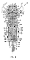
- Figure 2 shows an oil activated fuel injector of the present invention;
- Figure 3A shows a control valve body of the oil activated fuel injector of the
present invention with a spool in a closed position;
- Figure 3B shows the control valve body of the present invention with the spool in
the open position;
- Figure 4A shows a second embodiment of the control valve body of the present
invention with the spool in the closed position;
- Figure 4B shows the second embodiment of the control valve body of the present
invention with the spool in the open position;
- Figure 5 shows a third embodiment of the control valve body of the present
invention; and
- Figures 6-10 show performance charts of the oil activated fuel injector of the
present invention.
-
DETAILED DESCRIPTION OF A PREFERRED
EMBODIMENT OF THE INVENTION
-
The present invention is directed to an oil activated electronically, mechanically or
hydraulically controlled fuel injector which is capable of substantially decreasing and/or
preventing captured air from mixing with the working fluid such as, for example, hydraulic
oil, during the fuel injection process. The oil activated fuel injector of the present
invention will also avoid capturing of air in the control valve body as well as grooves or
orifices positioned in either a spool or the control valve body, itself. The present invention
is also capable of decreasing shot to shot variations in fuel injection at low fuel quantities
thus increasing the predictability of the fuel injector throughout a range of hydraulic oil
pressures. This increased predictability also leads to increased fuel efficiency even at
lower fuel quantities.
Embodiments of the Oil Activated Fuel
Injector of the Present Invention
-
Referring now to Figure 2, an overview of the fuel injector of the present invention
is shown. The fuel injector is generally depicted as reference numeral 100 and includes a
control valve body 102 as well as an intensifier body 120 and a nozzle 140. The control
valve body 102 includes an inlet area 104 which is in fluid communication with working
ports 106. At least one groove or orifice (hereinafter referred to as grooves) 108 are
positioned between and in fluid communication with the inlet area 104 and the working
ports 106. At least one of vent hole 110 (and preferably two ore more) is located in the
control body 102 which are in fluid communication with the working ports 106. In the
embodiments of the present invention, the vent holes 110 are arranged or designed to
eliminate or substantially reduce captured air in the working fluid within the working ports
106.
-
A spool 112 having at least one groove or orifice (hereinafter referred to as
grooves) 114 is slidably mounted within the control valve body 102. An open coil 116
and a closed coil 118 are positioned on opposing sides of the spool 112 and are energized
via a driver (not shown) to drive the spool 112 between a closed position and an open
position. In the open position, the grooves 114 of the spool 112 are aligned with the
grooves 108 of the valve control body 102 thus allowing the working fluid to flow
between the inlet area 104 and the working ports 106 of the valve control body 102.
-
Still referring to Figure 2, the intensifier body 120 is mounted to the valve control
body 102 via any conventional mounting mechanism. A seal 122 (e.g., o-ring) may be
positioned between the mounting surfaces of the intensifier body 120 and the valve control
body 102. A piston 124 is slidably positioned within the intensifier body 120 and is in
contact with an upper end of a plunger 126. An intensifier spring 128 surrounds a portion
(e.g., shaft) of the plunger 126 and is further positioned between the piston 124 and a
flange or shoulder 129 formed on an interior portion of the intensifier body 120. The
intensifier spring 128 urges the piston 122 and the plunger 126 in a first position
proximate to the valve control body 102. A plurality of venting and pressure release holes
130 and 132, respectively, are formed in the body of the intensifier body 120. The
plurality of venting and pressure release holes 130 and 132 are further positioned adjacent
the plunger 126.
-
A check disk 134 is positioned below the intensifier body 120 remote from the
valve control body 102. The combination of an upper surface 134a of the check disk 134,
an end portion 126a of the plunger 126 and an interior wall 120a of the intensifier body
120 forms a high pressure chamber 136. A fuel inlet check valve 138 is positioned within
the check disk 134 and provides fluid communication between the high pressure chamber
136 and a fuel area (not shown). This fluid communication allows fuel to flow into the
high pressure chamber 136 from the fuel area during an up-stroke of the plunger 126. The
pressure release hole 132 is also in fluid communication with the high pressure chamber
136 when the plunger 126 is urged into the first position; however, fluid communication is
interrupted when the plunger 126 is urged downwards towards the check disk 134. The
check disk 134 also includes an angled fuel bore 139 in fluid communication with the high
pressure chamber 136.
-
Figure 2 further shows the nozzle 140 and a spring cage 142. The spring cage 142
is positioned between the nozzle 140 and the check disk 134, and includes a straight fuel
bore 144 in fluid communication with the angled fuel bore 139 of the check disk 134. The
spring cage 142 also includes a centrally located bore 148 having a first bore diameter
148a and a second smaller bore diameter 148b. A spring 150 and a spring seat 152 are
positioned within the first bore diameter 148a of the spring cage 142, and a pin 154 is
positioned within the second smaller bore diameter 148b.
-
The nozzle 140 includes a second angled bore 146 in alignment with the straight
bore 139 of the spring cage 142. A needle 150 is preferably centrally located with the
nozzle 140 and is urged downwards by the spring 150 (via the pin 154). A fuel chamber
152 surrounds the needle 150 and is in fluid communication with the angled bore 146. In
embodiments, a nut 160 is threaded about the intensifier body 120, the check disk 134, the
nozzle 140 and the spring cage 142.
-
Figure 3A shows the control valve body 102 of Figure 2 with the spool 112 in the
closed or start position. In Figure 3A, the lower vent holes 110a are plugged or capped to
ensure that air 162 remains above the working fluid level 164 during the venting process.
Alternatively, the lower vent holes 110a may be entirely eliminated from the valve control
body 102. In these embodiments, the working fluid 164 rises to a level of the upper vent
holes 110b during the venting process. The working fluid 164 also fills the grooves 114 of
the spool 112; however, air 162 may remain in the upper portion of the grooves 108 and
the upper vent holes 110b of the valve control body 102. In this configuration, the air in
the upper vent holes 110b and upper portion of the grooves 108 is above the level of the
working fluid 164. In the closed position of Figure 3A, the working fluid 164 within the
inlet area 104 will not flow to the working ports 106 due to the non-alignment of the
grooves 108 and 114.
-
Figure 3B shows the control body 102 with the spool 112 in an open position. In
the open position of the spool 112, the grooves 108 of the valve control body 102 and the
grooves 114 of the spool 112 are in alignment with one another thus allowing the working
fluid 164 to flow from the inlet area 104 to the working ports 106. As seen from Figure
3B, during the flow of working fluid 164 only a small amount of air is captured and locked
in the grooves 108. Accordingly, only a small amount of air 162 is then captured in the
working fluid 164. This is because the air 162 remains above the working fluid level 164
when the spool 112 is in the closed position (Figure 3A). Thus, only a small amount of
captured air will have to be compressed and dissolved by the working fluid thus greatly
minimizing shot to shot fuel variations especially for low fuel quantities.
-
Figure 4A shows a second embodiment of the control valve body 102 with the
spool 112 in the closed position. In this embodiment, the vent holes 110 include an inlet
111 which is positioned above the grooves 108 of the valve control body 102 and the
grooves 114 of the spool 112. The position of the inlet 111 of the vent holes 110 will not
permit air to fill the grooves 108 and 114. This is because the position of the vent holes
110 is positioned such that the working fluid 164 will remain in the vent holes 110 during
and after the venting process, and air 162 will thus be prevented from entering the grooves
108 and 114. That is, the air 164 will always remains above the grooves 108 and 114.
Now, when the spool 112 is in the closed position and the venting process begins it is not
possible for the air 162 to enter the grooves 108 of the valve control body 102 and the
grooves 114 of the spool 112. Thus, as seen in Figure 4B, the working fluid 164 will flow
between the inlet 104 and the working ports 106 of the valve control body 102 without
any captured air therein.
-
Figure 5 shows an embodiment of the control valve body 102 of Figures 4A and
4B. In this embodiment, the vent holes 110 include a check valve 166. The check valve
166 includes a spring 168 which biases a ball, plate or cone 170 against a seat 172. The
vent holes may face downward due to the use of the check valve 166. During the venting
process, the working fluid 164 overcomes a spring force of the spring 168 and thus
disengages the ball 170 from the seat 172. This allows the working fluid 164 to vent from
the vent holes 110 during the venting process. When the spool 112 is in the open position
or venting stops, the ball 170 will be biased against the seat 172 and will prevent air from
entering the system. In this manner, when the spool 112 is in the closed position and the
venting process begins it is not possible for air 162 to enter or become locked in the
grooves 108 or 114. In this arrangement, air 162 will not be mixed with the working fluid
164 thus ensuring more consistent fuel consumption predictability and efficiency.
-
Figure 6 shows a chart depicting several tests of a conventional fuel injector (of
known design) and the oil activated fuel injector of Figures 2-3B at several different
testing pressures. The
lines 200 depict the results relating to the oil activated fuel injector
of the present invention and
lines 300 depict the results of the conventional fuel injector.
The test parameters included:
- 1. Engine speed: 1000 RPM
- 2. Pump speed: 1000 RPM
- 3. Engine Oil Temperature: approximately 93° Celsius
- 4. Calibration Fluid Temperature: approximately 40° Celsius.
-
-
Figure 6 clearly shows that the performance of the oil activated fuel injector of the
present invention is superior to that of a conventional fuel injector (i.e., a fuel injector
which does not prevent air from mixing with the working fluid) throughout a range of
testing pressures. The superior performance of the oil activated fuel injector of the
present invention is shown to be even greater at higher operating pressures such as, for
example, 160 bars. This superior performance is attributed to the fact that the oil
activated fuel injector of the present invention substantially prevents and, in embodiments,
completely eliminates the mixing of air with the working fluid. This is a direct result of the
placement and/or design of the vent holes 110 of the control valve body 102.
-
Figures 7-10 also show the superior performance of the oil activated fuel injector
of the present invention compared to a conventional fuel injector. Figures 7-10 use the
same test parameters of Figure 6.
Operation of the Oil Activated Fuel
Injector of the Present Invention
-
In operation, a driver (not shown) will first energize the open coil 116. The
energized open coil 116 will then shift the spool 112 from a start position to an open
position. In the open position, the grooves 108 of the control valve body 102 will become
aligned with the grooves 114 on the spool 112. The alignment of the grooves 108 and
114 will allow the pressurized working fluid to flow from the inlet area 104 to the working
ports 106 of the control valve body 102. As discussed in greater detail below, the
placement and/or design of the vent holes 110 of the control valve body 102 will eliminate
the mixing of air with the working fluid.
-
Once the pressurized working fluid is allowed to flow into the working ports 106 it
begins to act on the piston 124 and the plunger 126. That is, the pressurized working fluid
will begin to push the piston 124 and the plunger 126 downwards thus compressing the
intensifier spring 128. As the piston 124 is pushed downward, fuel in the high pressure
chamber will begin to be compressed via the end portion 126a of the plunger. The
compressed fuel will be forced through the bores 139, 144 and 146 and into the chamber
158 which surrounds the needle 156. As the plunger 126 is pushed downward, the fuel
inlet check valve 138 prevents fuel from flowing into the high pressure chamber 136 from
the fuel area. As the pressure working ports 106 increases, the fuel pressure will rise
above a needle check valve opening pressure until the needle spring 148 is urged upwards.
At this stage, the injection holes are open in the nozzle 140 thus allowing fuel to be
injected into the combustion chamber of the engine.
-
To end the injection cycle, the driver will energize the closed coil 118. The
magnetic force generated in the closed coil 118 will then shift the spool 112 into the
closed or start position which, in turn, will close the working ports 106 of the control
valve body 102. That is, the grooves 108 and 114 will no longer be in alignment thus
interrupting the flow of working fluid from the inlet area 104 to the working ports 106.
At this stage, the needle spring 150 will urge the needle 156 downward towards the
injection holes of the nozzle 140 thereby closing the injection holes. Similarly, the
intensifier spring 128 urges the plunger 126 and the piston 124 into the closed or first
position adjacent to the valve control body 102. As the plunger 126 moves upward, the
pressure release hole 132 will release pressure in the high pressure chamber 136 thus
allowing fuel to flow into the high pressure chamber 136 (via the fuel inlet check valve
138). Now, in the next cycle the fuel can be compressed in the high pressure chamber
136.
-
As the plunger 126 and the piston 124 move towards the valve control body 102,
the working fluid will begin to be vented through the vent holes 110 of the present
invention. This is due to the narrowing space between the piston 124 and the valve
control body 102. As now discussed below, the vent holes 110 are arranged or designed
to eliminate or substantially reduce captured air in the working fluid within the working
ports 106.
-
In the embodiment of Figures 3A and 3B, the lower vent holes 110a are plugged
or capped to ensure that air remains above the working fluid level during the venting
process. Alternatively, the lower vent holes 110a may be entirely eliminated from the
valve control body 102. In this embodiment, the working fluid rises to a level of the upper
vent holes 110b during the venting process. The working fluid also fills the grooves 114.
Any air in the system such as, for example, in the upper vent holes 110b and an upper
portion of the grooves 108 is above the level of the working fluid. In this arrangement,
during the next cycle when the spool 112 is opened, only a small amount of air is locked in
the grooves 108 and is captured in the working fluid. This is because the air remains
above the working fluid level when the spool 112 is in the closed position. Thus, only a
small amount of captured air will have to be compressed and dissolved by the working
fluid thus greatly minimizing shot to shot fuel variation.
-
In the embodiment of Figures 4A and 4B, the inlet 111 of the vent holes 110 are
positioned above the grooves 108 of the valve control body 102 and the grooves 114 of
the spool 112. This position will not permit air to fill the grooves 108 and 114 during the
venting process since any air in the vent holes will now always remain above the grooves
108 and 114. In the configuration of Figures 4A and 4B, when the spool 112 is again
opened the working fluid will flow between the inlet area 104 and the working ports 106
of the valve control body 102 without any captured air therein.
-
As to the embodiment of Figure 5, the vent holes 110 include a check valve 166
which prevents air from entering the system during the venting process. Thus, when the
spool 112 is in the closed position and the venting process begins it is not possible for air
to enter or become locked in the grooves 108 or 114. This ensures that no air will be
locked in the grooves 108 and 114 and mix with the working fluid thus providing for more
efficient fuel consumption.
-
While the invention has been described in terms of preferred embodiments, those
skilled in the art will recognize that the invention can be practiced with modification within
the spirit and scope of the appended claims.