EP1249598A2 - Oil activated fuel injector control valve - Google Patents
Oil activated fuel injector control valve Download PDFInfo
- Publication number
- EP1249598A2 EP1249598A2 EP02006871A EP02006871A EP1249598A2 EP 1249598 A2 EP1249598 A2 EP 1249598A2 EP 02006871 A EP02006871 A EP 02006871A EP 02006871 A EP02006871 A EP 02006871A EP 1249598 A2 EP1249598 A2 EP 1249598A2
- Authority
- EP
- European Patent Office
- Prior art keywords
- control valve
- valve body
- working
- port
- spool
- Prior art date
- Legal status (The legal status is an assumption and is not a legal conclusion. Google has not performed a legal analysis and makes no representation as to the accuracy of the status listed.)
- Withdrawn
Links
Images


Classifications
-
- F—MECHANICAL ENGINEERING; LIGHTING; HEATING; WEAPONS; BLASTING
- F02—COMBUSTION ENGINES; HOT-GAS OR COMBUSTION-PRODUCT ENGINE PLANTS
- F02M—SUPPLYING COMBUSTION ENGINES IN GENERAL WITH COMBUSTIBLE MIXTURES OR CONSTITUENTS THEREOF
- F02M57/00—Fuel-injectors combined or associated with other devices
- F02M57/02—Injectors structurally combined with fuel-injection pumps
- F02M57/022—Injectors structurally combined with fuel-injection pumps characterised by the pump drive
- F02M57/025—Injectors structurally combined with fuel-injection pumps characterised by the pump drive hydraulic, e.g. with pressure amplification
-
- F—MECHANICAL ENGINEERING; LIGHTING; HEATING; WEAPONS; BLASTING
- F02—COMBUSTION ENGINES; HOT-GAS OR COMBUSTION-PRODUCT ENGINE PLANTS
- F02M—SUPPLYING COMBUSTION ENGINES IN GENERAL WITH COMBUSTIBLE MIXTURES OR CONSTITUENTS THEREOF
- F02M55/00—Fuel-injection apparatus characterised by their fuel conduits or their venting means; Arrangements of conduits between fuel tank and pump F02M37/00
- F02M55/007—Venting means
-
- F—MECHANICAL ENGINEERING; LIGHTING; HEATING; WEAPONS; BLASTING
- F02—COMBUSTION ENGINES; HOT-GAS OR COMBUSTION-PRODUCT ENGINE PLANTS
- F02M—SUPPLYING COMBUSTION ENGINES IN GENERAL WITH COMBUSTIBLE MIXTURES OR CONSTITUENTS THEREOF
- F02M59/00—Pumps specially adapted for fuel-injection and not provided for in groups F02M39/00 -F02M57/00, e.g. rotary cylinder-block type of pumps
- F02M59/02—Pumps specially adapted for fuel-injection and not provided for in groups F02M39/00 -F02M57/00, e.g. rotary cylinder-block type of pumps of reciprocating-piston or reciprocating-cylinder type
- F02M59/10—Pumps specially adapted for fuel-injection and not provided for in groups F02M39/00 -F02M57/00, e.g. rotary cylinder-block type of pumps of reciprocating-piston or reciprocating-cylinder type characterised by the piston-drive
- F02M59/105—Pumps specially adapted for fuel-injection and not provided for in groups F02M39/00 -F02M57/00, e.g. rotary cylinder-block type of pumps of reciprocating-piston or reciprocating-cylinder type characterised by the piston-drive hydraulic drive
-
- F—MECHANICAL ENGINEERING; LIGHTING; HEATING; WEAPONS; BLASTING
- F02—COMBUSTION ENGINES; HOT-GAS OR COMBUSTION-PRODUCT ENGINE PLANTS
- F02M—SUPPLYING COMBUSTION ENGINES IN GENERAL WITH COMBUSTIBLE MIXTURES OR CONSTITUENTS THEREOF
- F02M59/00—Pumps specially adapted for fuel-injection and not provided for in groups F02M39/00 -F02M57/00, e.g. rotary cylinder-block type of pumps
- F02M59/44—Details, components parts, or accessories not provided for in, or of interest apart from, the apparatus of groups F02M59/02 - F02M59/42; Pumps having transducers, e.g. to measure displacement of pump rack or piston
- F02M59/46—Valves
- F02M59/466—Electrically operated valves, e.g. using electromagnetic or piezoelectric operating means
Definitions
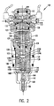
- the driver will energize the closed coil 118.
- the magnetic force generated in the closed coil 118 will then shift the spool 112 into the closed or start position which, in turn, will close the working ports 106 of the control valve body 102. That is, the grooves 108 and 114 will no longer be in alignment thus interrupting the flow of working fluid from the inlet area 104 to the working ports 106.
- the needle spring 150 will urge the needle 156 downward towards the injection holes of the nozzle 140 thereby closing the injection holes.
- the intensifier spring 128 urges the plunger 126 and the piston 124 into the closed or first position adjacent to the valve control body 102.
Landscapes
- Engineering & Computer Science (AREA)
- Chemical & Material Sciences (AREA)
- Combustion & Propulsion (AREA)
- Mechanical Engineering (AREA)
- General Engineering & Computer Science (AREA)
- Physics & Mathematics (AREA)
- Electromagnetism (AREA)
- Fuel-Injection Apparatus (AREA)
Abstract
Description
Claims (27)
- A control valve body adapted for use with a fuel injector, comprising:an inlet area;working ports in fluid communication with the inlet area, the working ports adapted to provide working fluid to an intensifier chamber of the fuel injector;at least one communication port in fluid communication with the inlet area and the working ports; andat least one vent hole in fluid communication with the working ports, the at least one vent hole preventing air from entering the working ports and mixing with the working fluid.
- The control valve body of claim 1, wherein the at least one vent hole includes at least one upper vent hole positioned above the working ports.
- The control valve body of claim 2, wherein the at least one vent hole includes at least one lower vent hole positioned below a level of the working fluid, the at least one lower vent hole being plugged or capped to prevent venting of the working fluid from the at least one lower vent hole.
- The control valve body of claim 1, wherein the at least one vent hole has an inlet which is positioned above the at least one communication port.
- The control valve body of claim 4, wherein the working fluid remains within the at least one vent hole which will prevent air from entering the working ports and mixing with the working fluid therein.
- The control valve body of claim 1, further comprising a check valve positioned within the at least one vent hole, the check valve allowing working fluid to be vented to a drain and preventing air from entering the working ports.
- The control valve body of claim 6, wherein the check valve includes one of a ball, plate and cone, the check valve further including a spring, the spring urges the ball, plate or cone against a seat located within the at least one vent hole.
- The control valve body of claim 6, wherein the at least one vent hole faces downward.
- The control valve body of claim 1, wherein the at least one communication port is two or more communication ports.
- The control valve body of claim 1, wherein the at least one communication port is one of an orifice and a groove.
- The control valve body of claim 1, further comprising a spool having at least one communication port, the spool being slidable between a first position and a second position, the at least one communication port of the spool and the at least one communication port being in alignment when the spool is in the first position, the at least one vent hole preventing air from entering the at least one communication port of the spool.
- The control valve body of claim 11, wherein the at least one communication port of the spool is one of a groove and an orifice and air is prevented from being locked in the groove or orifice of the spool.
- The control valve body of claim 1, wherein the at least one communication port is two or more communication ports.
- A control valve body for use with a fuel injector, comprising:an oil inlet area;at least one port in fluid communication with the oil inlet area, the at least one port adapted for transporting oil between the oil inlet area and an intensifier chamber of the fuel injector;an aperture having at least one communication port positioned about a surface of the aperture, the at least one communication port providing a flow path for the oil between the at least one port and the oil inlet area;a spool positioned within the aperture and slideable between a first position and a second position, the spool including at least one communication port which is in alignment with the at least one communication port of the aperture when the spool is in the first position;at least one vent port for venting the oil from the control valve body when the spool is in the second position, the at least one vent port being positioned above a level of the oil and preventing air from entering the at least one communication port of the spool.
- The control valve body of claim 14, wherein the at least one vent port includes an inlet above the at least one communication port of the spool and the aperture.
- The control valve body of claim 15, further including a check valve positioned at the inlet of the at least one vent port.
- The control valve body of claim 15, wherein the check valve includes one of a ball, plate and cone and a spring mechanism, wherein the spring urges the ball, plate or cone against a seat of the check valve after a venting of the oil.
- The control valve body of claim 14, wherein the at least one vent hole includes an upper set of vent holes and a lower set of vent holes, the upper set of vent holes being positioned above the oil and the lower set of vent holes being capped or plugged.
- The control valve body of claim 14, wherein the at least one communication port of the aperture and the spool is one of a groove and an orifice.
- An oil activated fuel injector, comprising:a control valve body, the control body including:an inlet area;at least one working port in fluid communication with the inlet area;at least one communication port positioned between and in fluid communication with the inlet area and the at least one working port;a spool having at least one fluid path which is alignable with the at least one communication port;at least one vent hole in fluid communication with the at least one working port, the at least one vent hole being positioned above the at least one working port to reduce captured air in the at least one working port;an intensifier body mounted to the control valve body, the intensifier body including a centrally located bore and a shoulder;a piston slidably positioned within centrally located bore of the intensifier body;a plunger contacting the piston, the plunger having a first end, a second end and a shaft;an intensifier spring surrounding the shaft of the plunger and further positioned between the piston and the shoulder of the intensifier body, the intensifier spring urging the piston and the plunger in a first position proximate to the valve control body;a high pressure fuel chamber formed at the second end of the plunger;a nozzle having a fuel bore in fluid communication with the high pressure chamber;a needle positioned within the nozzle; anda fuel chamber surrounding the needle and in fluid communication with the fuel bore.
- The fuel injector of claim 20, wherein the at least one vent hole has an inlet which is positioned above the at least one fluid path of the spool.
- The fuel injector of claim 21, wherein working fluid remains within the at least one vent hole which eliminates air from entering the at least one working port and mixing with the working fluid therein.
- The fuel injector of claim 21, further comprising a check valve positioned within the at least one vent hole, the check valve allowing working fluid to be vented to a drain and preventing air from entering the at least one working port.
- The fuel injector of claim 20, wherein the at least one vent hole includes an upper set of vent holes and a lower set of vent holes, the upper set of vent holes being positioned above working fluid in the at least one working port and the lower set of vent holes being capped or plugged.
- The fuel injector of claim 20, further comprising:a check disk positioned below the intensifier body remote from the valve control body, wherein a combination of an upper surface of the check disk, the second end of the plunger and an interior wall of the intensifier body forms the high pressure chamber; anda fuel bore in fluid communication with the fuel bore of the nozzle.
- The fuel injector of claim 25, further comprising a fuel inlet check valve positioned within the check disk and providing fluid communication between the high pressure chamber and a fuel area during an upstroke of the plunger.
- The fuel injector of claim 26, further comprising a spring cage positioned between the nozzle and the check disk, the spring cage including a spring which is in biasing contact with the needle.
Applications Claiming Priority (2)
| Application Number | Priority Date | Filing Date | Title |
|---|---|---|---|
| US828169 | 2001-04-09 | ||
| US09/828,169 US6631853B2 (en) | 2001-04-09 | 2001-04-09 | Oil activated fuel injector control valve |
Publications (2)
| Publication Number | Publication Date |
|---|---|
| EP1249598A2 true EP1249598A2 (en) | 2002-10-16 |
| EP1249598A3 EP1249598A3 (en) | 2004-09-08 |
Family
ID=25251072
Family Applications (1)
| Application Number | Title | Priority Date | Filing Date |
|---|---|---|---|
| EP02006871A Withdrawn EP1249598A3 (en) | 2001-04-09 | 2002-03-26 | Oil activated fuel injector control valve |
Country Status (3)
| Country | Link |
|---|---|
| US (1) | US6631853B2 (en) |
| EP (1) | EP1249598A3 (en) |
| JP (1) | JP2002327662A (en) |
Cited By (5)
| Publication number | Priority date | Publication date | Assignee | Title |
|---|---|---|---|---|
| WO2006048375A1 (en) * | 2004-11-05 | 2006-05-11 | Robert Bosch Gmbh | Fuel injection device |
| WO2017197282A1 (en) | 2016-05-12 | 2017-11-16 | Briggs & Stratton Corporation | Fuel delivery injector |
| US10947940B2 (en) | 2017-03-28 | 2021-03-16 | Briggs & Stratton, Llc | Fuel delivery system |
| US11286895B2 (en) | 2012-10-25 | 2022-03-29 | Briggs & Stratton, Llc | Fuel injection system |
| US11668270B2 (en) | 2018-10-12 | 2023-06-06 | Briggs & Stratton, Llc | Electronic fuel injection module |
Families Citing this family (9)
| Publication number | Priority date | Publication date | Assignee | Title |
|---|---|---|---|---|
| DE10160263A1 (en) * | 2001-12-07 | 2003-06-18 | Bosch Gmbh Robert | Fuel injection device for an internal combustion engine |
| US20040011900A1 (en) * | 2002-05-22 | 2004-01-22 | Jens Gebhardt | Fuel injector assembly |
| US8382006B2 (en) * | 2002-05-22 | 2013-02-26 | Jens Gebhardt | Fuel injector assembly |
| US7007860B2 (en) * | 2002-08-30 | 2006-03-07 | Caterpillar Inc. | Plunger cavity pressure control for a hydraulically-actuated fuel injector |
| US7044400B2 (en) * | 2002-09-03 | 2006-05-16 | Siemens Diesel Systems Technology | Solenoid end cap assembly with flat surface |
| US7059301B2 (en) * | 2003-02-20 | 2006-06-13 | Caterpillar Inc. | End of injection rate shaping |
| DK178674B1 (en) * | 2015-03-20 | 2016-10-24 | Man Diesel & Turbo Filial Af Man Diesel & Turbo Se Tyskland | Fuel valve for injecting a low flashpoint fuel into a combustion chamber of a large self-igniting turbocharged two-stroke internal combustion engine |
| CN109372658B (en) * | 2018-12-10 | 2020-10-13 | 大连理工大学 | Gas injector of gas engine and working method thereof |
| US11174732B1 (en) * | 2020-05-12 | 2021-11-16 | Pratt & Whitney Canada Corp. | Rotary engine lubrication system using intensifier injector |
Family Cites Families (17)
| Publication number | Priority date | Publication date | Assignee | Title |
|---|---|---|---|---|
| US4182492A (en) | 1978-01-16 | 1980-01-08 | Combustion Research & Technology, Inc. | Hydraulically operated pressure amplification system for fuel injectors |
| US4406307A (en) * | 1981-03-31 | 1983-09-27 | Double A Products Company | Directional valve with spool transfer loop |
| CA1312018C (en) * | 1987-03-30 | 1992-12-29 | John F. Church | Fuel filter assembly with heater |
| WO1993008400A1 (en) * | 1991-10-21 | 1993-04-29 | Caterpillar Inc. | Engine combustion system |
| JP2812102B2 (en) | 1992-10-15 | 1998-10-22 | 株式会社デンソー | Fuel supply device for internal combustion engine |
| US5640987A (en) * | 1994-04-05 | 1997-06-24 | Sturman; Oded E. | Digital two, three, and four way solenoid control valves |
| US5460329A (en) * | 1994-06-06 | 1995-10-24 | Sturman; Oded E. | High speed fuel injector |
| US5479901A (en) | 1994-06-27 | 1996-01-02 | Caterpillar Inc. | Electro-hydraulic spool control valve assembly adapted for a fuel injector |
| US5454359A (en) | 1994-12-01 | 1995-10-03 | Navistar International Transportation Corp. | Continuous high pressure rail deaeration system for fuel injection system |
| US5878720A (en) | 1997-02-26 | 1999-03-09 | Caterpillar Inc. | Hydraulically actuated fuel injector with proportional control |
| US6105616A (en) | 1997-03-28 | 2000-08-22 | Sturman Industries, Inc. | Double actuator control valve that has a neutral position |
| US6119960A (en) | 1998-05-07 | 2000-09-19 | Caterpillar Inc. | Solenoid actuated valve and fuel injector using same |
| US6085991A (en) * | 1998-05-14 | 2000-07-11 | Sturman; Oded E. | Intensified fuel injector having a lateral drain passage |
| US6053421A (en) | 1998-05-19 | 2000-04-25 | Caterpillar Inc. | Hydraulically-actuated fuel injector with rate shaping spool control valve |
| US5964406A (en) | 1998-05-28 | 1999-10-12 | Caterpillar Inc. | Valve area scheduling in a double acting piston for a hydraulically-actuated fuel injector |
| DE19907678A1 (en) * | 1999-02-23 | 2000-08-24 | Hydraulik Ring Gmbh | Control edge manufacturing method for valve, preferably for fuel injector of combustion machine, manufacturing co-operating control edges in single processing step by device of single tool |
| KR20020005007A (en) * | 1999-05-18 | 2002-01-16 | 인터내셔널 엔진 인터렉츄얼 프로퍼티 캄파니, 엘엘씨 | Double acting two stage hydraulic control device |
-
2001
- 2001-04-09 US US09/828,169 patent/US6631853B2/en not_active Expired - Lifetime
-
2002
- 2002-03-26 EP EP02006871A patent/EP1249598A3/en not_active Withdrawn
- 2002-04-09 JP JP2002106122A patent/JP2002327662A/en active Pending
Cited By (9)
| Publication number | Priority date | Publication date | Assignee | Title |
|---|---|---|---|---|
| WO2006048375A1 (en) * | 2004-11-05 | 2006-05-11 | Robert Bosch Gmbh | Fuel injection device |
| US7926736B2 (en) | 2004-11-05 | 2011-04-19 | Robert Bosch Gmbh | Fuel injection apparatus |
| US11286895B2 (en) | 2012-10-25 | 2022-03-29 | Briggs & Stratton, Llc | Fuel injection system |
| WO2017197282A1 (en) | 2016-05-12 | 2017-11-16 | Briggs & Stratton Corporation | Fuel delivery injector |
| EP3455498A4 (en) * | 2016-05-12 | 2020-01-01 | Briggs & Stratton Corporation | KRAFTSTOFFFÖRDERINJEKTOR |
| US10677205B2 (en) | 2016-05-12 | 2020-06-09 | Briggs & Stratton Corporation | Fuel delivery injector |
| US11002234B2 (en) | 2016-05-12 | 2021-05-11 | Briggs & Stratton, Llc | Fuel delivery injector |
| US10947940B2 (en) | 2017-03-28 | 2021-03-16 | Briggs & Stratton, Llc | Fuel delivery system |
| US11668270B2 (en) | 2018-10-12 | 2023-06-06 | Briggs & Stratton, Llc | Electronic fuel injection module |
Also Published As
| Publication number | Publication date |
|---|---|
| JP2002327662A (en) | 2002-11-15 |
| US6631853B2 (en) | 2003-10-14 |
| EP1249598A3 (en) | 2004-09-08 |
| US20020145056A1 (en) | 2002-10-10 |
Similar Documents
| Publication | Publication Date | Title |
|---|---|---|
| US6631853B2 (en) | Oil activated fuel injector control valve | |
| KR100941794B1 (en) | Fuel injector with controlled high pressure fuel passage | |
| EP0774067B1 (en) | Solenoid actuated miniservo spool valve | |
| US5852997A (en) | Common rail injector | |
| JPH07332193A (en) | Fuel injection valve for internal combustion engine | |
| JPH01151768A (en) | Electronic unit injector | |
| JPH08109860A (en) | Flow control valve for fuel injector nozzle | |
| KR100340741B1 (en) | Fuel injection device of internal combustion engine | |
| EP1163440A1 (en) | Fuel injector | |
| US6474304B1 (en) | Double-acting two-stage hydraulic control device | |
| US6715694B2 (en) | Control valve body for an oil activated fuel injector | |
| JP2005520968A (en) | Fuel injection device for internal combustion engine | |
| JP2002021669A (en) | Pressure controlled injector with variable register injection nozzle | |
| US6003497A (en) | Mechanically actuated hydraulically amplified fuel injector with electrically controlled pressure relief | |
| US6913212B2 (en) | Oil activated fuel injector control with delay plunger | |
| US6749130B2 (en) | Check line valve faster venting method | |
| US6526943B2 (en) | Control valve for hydraulically oil activated fuel injector | |
| US6923382B2 (en) | Hydraulically actuated injector with delay piston and method of using the same | |
| JP4075894B2 (en) | Fuel injection device | |
| US6591812B2 (en) | Rail connection with rate shaping behavior for a hydraulically actuated fuel injector | |
| CN112041555B (en) | Injector for injecting fuel | |
| JPH10184486A (en) | Engine fuel injection device | |
| JPH0467021B2 (en) | ||
| CN1342245A (en) | Pressure accumulator-injector | |
| US20040124275A1 (en) | Fuel injection system for internal combustion engines |
Legal Events
| Date | Code | Title | Description |
|---|---|---|---|
| PUAI | Public reference made under article 153(3) epc to a published international application that has entered the european phase |
Free format text: ORIGINAL CODE: 0009012 |
|
| AK | Designated contracting states |
Kind code of ref document: A2 Designated state(s): AT BE CH CY DE DK ES FI FR GB GR IE IT LI LU MC NL PT SE TR |
|
| AX | Request for extension of the european patent |
Free format text: AL;LT;LV;MK;RO;SI |
|
| PUAL | Search report despatched |
Free format text: ORIGINAL CODE: 0009013 |
|
| AK | Designated contracting states |
Kind code of ref document: A3 Designated state(s): AT BE CH CY DE DK ES FI FR GB GR IE IT LI LU MC NL PT SE TR |
|
| AX | Request for extension of the european patent |
Extension state: AL LT LV MK RO SI |
|
| AKX | Designation fees paid | ||
| REG | Reference to a national code |
Ref country code: DE Ref legal event code: 8566 |
|
| STAA | Information on the status of an ep patent application or granted ep patent |
Free format text: STATUS: THE APPLICATION IS DEEMED TO BE WITHDRAWN |
|
| 18D | Application deemed to be withdrawn |
Effective date: 20050309 |