EP1249567B1 - An inner actuation means for doors of automobiles - Google Patents
An inner actuation means for doors of automobiles Download PDFInfo
- Publication number
- EP1249567B1 EP1249567B1 EP02007618A EP02007618A EP1249567B1 EP 1249567 B1 EP1249567 B1 EP 1249567B1 EP 02007618 A EP02007618 A EP 02007618A EP 02007618 A EP02007618 A EP 02007618A EP 1249567 B1 EP1249567 B1 EP 1249567B1
- Authority
- EP
- European Patent Office
- Prior art keywords
- handle
- damper
- leg
- door
- housing
- Prior art date
- Legal status (The legal status is an assumption and is not a legal conclusion. Google has not performed a legal analysis and makes no representation as to the accuracy of the status listed.)
- Expired - Lifetime
Links
- 229920001296 polysiloxane Polymers 0.000 description 5
- 238000009966 trimming Methods 0.000 description 3
- 230000006835 compression Effects 0.000 description 2
- 238000007906 compression Methods 0.000 description 2
- 238000010276 construction Methods 0.000 description 2
- 238000013016 damping Methods 0.000 description 2
- 238000004519 manufacturing process Methods 0.000 description 2
- 244000208734 Pisonia aculeata Species 0.000 description 1
- 230000015572 biosynthetic process Effects 0.000 description 1
- 238000007789 sealing Methods 0.000 description 1
Images

Classifications
-
- E—FIXED CONSTRUCTIONS
- E05—LOCKS; KEYS; WINDOW OR DOOR FITTINGS; SAFES
- E05B—LOCKS; ACCESSORIES THEREFOR; HANDCUFFS
- E05B85/00—Details of vehicle locks not provided for in groups E05B77/00 - E05B83/00
- E05B85/10—Handles
- E05B85/12—Inner door handles
-
- E—FIXED CONSTRUCTIONS
- E05—LOCKS; KEYS; WINDOW OR DOOR FITTINGS; SAFES
- E05B—LOCKS; ACCESSORIES THEREFOR; HANDCUFFS
- E05B77/00—Vehicle locks characterised by special functions or purposes
- E05B77/42—Means for damping the movement of lock parts, e.g. slowing down the return movement of a handle
-
- Y—GENERAL TAGGING OF NEW TECHNOLOGICAL DEVELOPMENTS; GENERAL TAGGING OF CROSS-SECTIONAL TECHNOLOGIES SPANNING OVER SEVERAL SECTIONS OF THE IPC; TECHNICAL SUBJECTS COVERED BY FORMER USPC CROSS-REFERENCE ART COLLECTIONS [XRACs] AND DIGESTS
- Y10—TECHNICAL SUBJECTS COVERED BY FORMER USPC
- Y10S—TECHNICAL SUBJECTS COVERED BY FORMER USPC CROSS-REFERENCE ART COLLECTIONS [XRACs] AND DIGESTS
- Y10S292/00—Closure fasteners
- Y10S292/22—Inertia operated
-
- Y—GENERAL TAGGING OF NEW TECHNOLOGICAL DEVELOPMENTS; GENERAL TAGGING OF CROSS-SECTIONAL TECHNOLOGIES SPANNING OVER SEVERAL SECTIONS OF THE IPC; TECHNICAL SUBJECTS COVERED BY FORMER USPC CROSS-REFERENCE ART COLLECTIONS [XRACs] AND DIGESTS
- Y10—TECHNICAL SUBJECTS COVERED BY FORMER USPC
- Y10T—TECHNICAL SUBJECTS COVERED BY FORMER US CLASSIFICATION
- Y10T292/00—Closure fasteners
- Y10T292/57—Operators with knobs or handles
-
- Y—GENERAL TAGGING OF NEW TECHNOLOGICAL DEVELOPMENTS; GENERAL TAGGING OF CROSS-SECTIONAL TECHNOLOGIES SPANNING OVER SEVERAL SECTIONS OF THE IPC; TECHNICAL SUBJECTS COVERED BY FORMER USPC CROSS-REFERENCE ART COLLECTIONS [XRACs] AND DIGESTS
- Y10—TECHNICAL SUBJECTS COVERED BY FORMER USPC
- Y10T—TECHNICAL SUBJECTS COVERED BY FORMER US CLASSIFICATION
- Y10T292/00—Closure fasteners
- Y10T292/82—Knobs
Definitions
- This invention relates to an inner actuation means for doors of automobiles according to the preamble of claim 1 or 2.
- DE 199 07 683 has made known an inner actuation means for doors wherein a lever-like handle is supported so as to be pivotable about an axis within a housing which, in turn, is attached to the door. A portion of the handle is connected to the door lock via a linkage or actuating cable. A spring biases the handle into a rest position. A portion of the handle is toothed and engages with a pinion which is seated on the axle of a silicone rotary damper. Such an assembly efficiently meets the purpose of damping the pull-back motion of the door inside lever. The assembly described has a fixed geometrical association of its parts or components. Frequently, there is not sufficient space to integrate the known inner actuation means for doors in the automobile door. DE 4233037 A discloses an outer door handle which is supported for linear movement and equipped with a linear damper. The linear damper is integrated in a portion of the door handle.
- the inner actuation means for doors provides a linear damper having a housing linked to a portion of the door remote from the handle.
- a piston rod extends far beyond the damper housing and is linked to the other leg of the handle.
- the linear damper is preferably a so-called air damper which is preferably fitted with a free-moving device.
- air dampers are known as such. They mostly use a sealing member which is very permeable to air in one direction and is hardly permeable to air in the other direction. Air dampers have a number of advantages.
- an air damper Because of its geometrical set-up, an air damper has an integrated free-moving device which can be employed for the direction of handle actuation. Furthermore, an air damper is easier to manufacture with less expenditure than a so-called silicone damper (rotary damper) having a free-moving device.
- An air damper is nearly independent on temperature. Its temperature dependence caused by different expansion coefficients of the parts it uses is negligible.
- a silicone damper the viscosity of which governs the braking torque features a heavy dependence on temperature. If there are below-zero temperatures the handle will be restored distinctly more slowly, which does not allow to close the door quickly.
- a linear damper has the advantage to be disposable at many points adjacent to the inner actuation means for doors, e.g. on the housing of the handle, the sheet of the door, the door trimming, etc.
- the working directions of the linkage or cable, on one hand, and the linear damper, on the other, are approximately parallel. A particularly space-saving solution is obtained, as a result.
- an air damper can be disposed to react to a pressure or pull. If it is disposed to react to pressure the restoring forces which can be absorbed are higher than those for a reaction to a pull.
- the restoring spring is disposed in the housing of the air damper.
- the spring may be a simple compression spring which is easier to manufacture and mount than are the common leg springs on the axle of the inner actuation means for doors. Since the latter constitutes a potential source of noise the inventive configuration largely suppresses the formation of noise, particularly if a spring is used the wire of which is encased in plastic, in another aspect of the invention.
- the inventive solution of claim 2 provides a rotary damper which is fixedly attached to the door remote from the handle and has a pinion, and a portion of the handle has hinged thereto a toothed rod which is guided by a guide means, the guide means holding the toothed rod in engagement with the pinion.
- the rotary damper may be a silicone damper which is mounted on a location remote from the handle. Since the guide means causes the toothed rod to engage the pinion any tolerances of the handle shell, axle bearing, and handle are insignificant. Using guide means also allows the toothed rack to engage the pinion at a low noise.
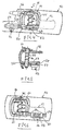
- a shell 10 is outlined which is set into the inner trimming of an automobile door (not shown).
- An actuation lever 12 is located within the shell 10 and, therefore, is partially shown in phantom lines in Fig. 1. It extends towards the outer surface of the door through the shell 10 into a housing 14 which retains a bearing pin 16.
- the actuation lever 12 has two legs 18, 20 which are linked to each other via a bent portion 22.
- Legs 18, 20 have apertures through which the bearing pin 16 extends.
- the leg 18, for example, has hinged thereto a pulling cable of a cable mechanism via a hole 24 as can be seen at 26 in Fig. 1.
- a U-shaped component 28 Connected to the cable is a U-shaped component 28 which is hinged to the leg 18 via a pin link or the like.
- Fig. 1 further illustrates a linear air damper 30.
- the air damper 30, which is of a design known as such, has a piston 32 with a ring seal 34 which is configured such as to cause the air damper to let pass more air in one direction and to let pass less air in the other direction, thus effecting a damping action in one direction and causing a free motion in the other.
- the air damper 30 is hinged to the shell 10 at 36. It is understood that it can also be fixedly hinged to the sheet of the door on the door trimming or another component. Thus, the position of the damper 30 is relatively random. In the case shown, the axle of the damper 30 is approximately parallel to the working direction of the cable 26, which saves particularly much space.
- the piston rod 38 is led out of the housing of the damper 30 and is designed in a fork shape at 40 at the end in order to be hinged to leg 20 of lever 12.
- a restoring spring 42 for the lever 12 e.g. a compression spring, is seated on the piston rod 38 in the housing. This way realizes a low-noise arrangement of the spring, particularly if the spring is made of a plastic-coated wire.
- Fig. 2 The illustration of Fig. 2 is merely intended to elucidate the structure of the lever 12 and housing 14 with a restoring spring 44, however, being disposed on the bearing pin 16 in contrast to Fig. 1.
- Fig. 3 illustrates the same components as does Fig. 1. Therefore, they are given the same reference numbers.
- the only distinction from Fig. 1 is that the linear damper 30 is disposed on the opposite side.
- the restoring spring 42 is a tension spring, for example.
- the embodiment of Fig. 4 also provides nearly the same parts as in the embodiment of Fig. 1. Therefore, the same reference numbers are used again.
- a restoring spring 44 is disposed on the bearing axle 16 like in Fig. 2.
- a toothed rack 50 is hinged to the leg 20 at 52.
- the toothed rack extends through a guide 54 which is mounted on a rotatably supported rotary damper 56 that has a pinion 58.
- Such rotary or silicone dampers are generally known.
- Actuating the lever 12 moves the toothed rack 50 linearly and pivots it simultaneously.
- the guide 54 joins this pivoting motion while ensuring that the teeth 58 of the toothed rack 50 is in permanent engagement with the pinion 58.
- the toothed rack 50 and the pinion 58 are preferably made of plastic to bring about a low-noise interengagement.
- Fig. 6 The distinction of the embodiment of Fig. 6 from that of Fig. 4 is that the toothed rack 50 is disposed on the side opposed to that of Fig. 4. However, the remaining components are the same except for the guide 54 which, in the embodiment of Fig. 6, is composed of two guide portions which are pivotally or rotatably supported about the rotary damper 56 via a joint structural member 60 in order to join the pivoting motion of the toothed rack 50 when it is actuated.
- guide 54 which, in the embodiment of Fig. 6, is composed of two guide portions which are pivotally or rotatably supported about the rotary damper 56 via a joint structural member 60 in order to join the pivoting motion of the toothed rack 50 when it is actuated.
- the rotary damper in the embodiment of Figures 4 to 6 may also be fitted with a free-moving device.
Landscapes
- Lock And Its Accessories (AREA)
Description
- Fig. 1
- schematically shows an inner actuation means for doors as seen from outside with a linear damper according to the invention.
- Fig. 2
- shows a section taken through the assembly of Fig. 1 along lines 2 - 2.
- Fig. 3
- shows an assembly similar to that of Fig. 1, but with the linear damper placed at a different point.
- Fig. 4
- shows an assembly of an inner actuation means for doors similar to that of Fig. 1, but with a rotary damper.
- Fig. 5
- shows a section taken through the assembly of Fig. 4 along lines 5 - 5.
- Fig. 6
- shows an assembly similar to that of Fig. 4, but with the rotary damper placed at a different point.
Claims (6)
- Inner actuation means for doors of automobiles comprising a lever-like handle (12) adapted to be pivoted about an axis (16) within a housing (10) which is attached to the door, the handle (12) having a handle portion on one side of the axis (16) and a first leg (18) and a second leg (20) on the other side of the axis, a linkage or an actuating cable (26) which is led to a door lock and engages one leg (18), spring means (42, 44) which bias the handle into a rest position and a damper (30) which cooperates with the other leg (20) of the handle (12) such that the movement of the handle (12) into the rest position is damped, characterized in that the damped is a linear damper (30) having a housing linked (36) to a portion of the door remote from the handle (12), a piston (32) within the damper housing and a piston rod (38) which extends far beyond the damper housing, the piston rod (38) being linked to the other leg (20) of the handle (12).
- Inner actuation means for doors of automobiles comprising a lever-like handle (12) adapted to be pivoted about an axis (16) within a housing (10) which is attached to the door, the handle (12) having a handle portion on one side of the axis (16) and a first leg (18) and a second leg (20) on the other side of the axis, a linkage or an actuating cable (26) which is led to a door lock and engages the one leg (18) of the handle at the other hand, spring means (44) which bias the handle (12) into a rest position and a damper (56) which cooperates with the other leg (20) of the handle such that the movement of the handle (12) into the rest position is damped, characterized in that the damper is a rotary damper (56) which is fixedly attached to the door remote from the handle (12), the rotary damper (56) including a pinion (58) and a tooth rod (50), the tooth rod (50), being linked to the other leg (20) and being guided by guide means (54), the guide means (54) being pivotally supported by a portion of the door and designed to hold the tooth rod (56) into engagement with the pinion (58).
- The actuation means of claim 1 or 2, wherein the effecting direction of the linkage or the actuating cable (26) and that of the piston rod (38) or the tooth rod (50), respectively, are approximately parallel.
- The actuation means of claim 1, wherein the housing of the linear damper (30) is linked to the housing (10) of the handle (12), to the sheet of the door or to the lining of the door.
- The actuation means of claim 1, wherein spring means (42) are located in the housing of the linear damper (30).
- The actuation means of claim 5, wherein the spring means (42) in the housing of the linear damper are made of wire coated with plastic material.
Applications Claiming Priority (2)
| Application Number | Priority Date | Filing Date | Title |
|---|---|---|---|
| DE10118658A DE10118658A1 (en) | 2001-04-14 | 2001-04-14 | Interior door actuation for automobiles |
| DE10118658 | 2001-04-14 |
Publications (2)
| Publication Number | Publication Date |
|---|---|
| EP1249567A1 EP1249567A1 (en) | 2002-10-16 |
| EP1249567B1 true EP1249567B1 (en) | 2004-06-30 |
Family
ID=7681632
Family Applications (1)
| Application Number | Title | Priority Date | Filing Date |
|---|---|---|---|
| EP02007618A Expired - Lifetime EP1249567B1 (en) | 2001-04-14 | 2002-04-04 | An inner actuation means for doors of automobiles |
Country Status (5)
| Country | Link |
|---|---|
| US (1) | US6874829B2 (en) |
| EP (1) | EP1249567B1 (en) |
| CA (1) | CA2381552C (en) |
| DE (2) | DE10118658A1 (en) |
| ES (1) | ES2219599T3 (en) |
Families Citing this family (12)
| Publication number | Priority date | Publication date | Assignee | Title |
|---|---|---|---|---|
| DE10348942B4 (en) * | 2003-10-18 | 2005-10-06 | Daimlerchrysler Ag | Locking device with noise optimization |
| JP4536580B2 (en) | 2004-05-13 | 2010-09-01 | 株式会社ニフコ | Automotive door handle equipment |
| DE102004058874A1 (en) * | 2004-12-06 | 2006-06-08 | Huf Hülsbeck & Fürst Gmbh & Co. Kg | Outside door handle for a motor vehicle |
| DE202005002960U1 (en) | 2005-01-21 | 2006-06-01 | Liebherr-Hausgeräte Ochsenhausen GmbH | Refrigerator and / or freezer door handle |
| DE102007029679B4 (en) * | 2007-06-27 | 2012-09-27 | Audi Ag | Actuation system for a vehicle wing and emergency release system |
| DE102007057807A1 (en) * | 2007-11-30 | 2009-06-04 | Volkswagen Ag | Door interior trim fitting and mounting procedure |
| US8029032B1 (en) * | 2008-02-01 | 2011-10-04 | Lei Yang | Automotive door handle assembly with directly coupled-inertia activated mechanism |
| DE102008047475A1 (en) * | 2008-09-17 | 2010-04-15 | Bayerische Motoren Werke Aktiengesellschaft | Door i.e. driver-side door, unlocking device for motor vehicle i.e. passenger car, has door inner handle swung out from inner door cladding and manually operatable for door unlocking in operating position |
| WO2010098774A1 (en) * | 2009-02-28 | 2010-09-02 | Hewlett-Packard Development Company, L.P. | Latch system |
| KR101650307B1 (en) * | 2010-05-07 | 2016-09-05 | 삼성전자주식회사 | Door handle and refrigerator having the same |
| JP5460478B2 (en) * | 2010-06-18 | 2014-04-02 | 株式会社パイオラックス | Locking device |
| ITMI20112367A1 (en) * | 2011-12-22 | 2013-06-23 | Valeo Spa | SAFETY DEVICE FOR A VEHICLE DOOR HANDLE. |
Family Cites Families (18)
| Publication number | Priority date | Publication date | Assignee | Title |
|---|---|---|---|---|
| US1688472A (en) * | 1923-03-30 | 1928-10-23 | Sargent & Co | Latch |
| US2763888A (en) * | 1951-02-20 | 1956-09-25 | Billeter Ernst | Door-closing mechanism |
| US2851296A (en) * | 1954-02-01 | 1958-09-09 | August Kobeli | Door latching mechanism |
| US3025091A (en) * | 1959-03-20 | 1962-03-13 | Renault | Safety devices for locking from inside the doors of automobile vehicles |
| US4540208A (en) * | 1980-05-09 | 1985-09-10 | Reliable Security Systems, Inc. | Point-of-egress control device for safely securing emergency exit doors |
| JPH0739771B2 (en) * | 1988-03-31 | 1995-05-01 | 株式会社アルファ | Door handle device |
| JPH0543169Y2 (en) * | 1988-09-19 | 1993-10-29 | ||
| DE3931866C1 (en) * | 1989-09-23 | 1991-03-21 | Mercedes-Benz Aktiengesellschaft, 7000 Stuttgart, De | |
| US5219192A (en) * | 1992-07-14 | 1993-06-15 | Securitech Group, Inc. | Removable spindle |
| DE4233037A1 (en) * | 1992-10-01 | 1994-04-14 | Daimler Benz Ag | Damped handle mechanism for door on vehicle - incorporates air dashpot with piston moving inside cylinder with tapered bore |
| US5531489A (en) * | 1994-09-23 | 1996-07-02 | Atoma International Inc. | Anti-kink cable for automotive door handles |
| US5690194A (en) * | 1995-10-30 | 1997-11-25 | Illinois Tool Works Inc. | One-way pivoting gear damper |
| US5743575A (en) * | 1997-01-27 | 1998-04-28 | Adac Plastics, Inc. | Fluid-damped automotive door latch actuator |
| DE19907683A1 (en) * | 1999-02-23 | 2000-08-31 | Itw Ateco Gmbh | Door actuation for automobiles |
| DE19907883A1 (en) | 1999-02-24 | 2000-08-31 | Tox Pressotechnik Gmbh | Hydropneumatic pressure intensifier |
| US6367124B1 (en) * | 1999-09-09 | 2002-04-09 | Illinois Tool Works Inc. | Damper and a door handle |
| US6264257B1 (en) * | 1999-10-08 | 2001-07-24 | Adac Plastics, Inc. | Motor vehicle door handle assembly |
| US6397436B1 (en) * | 2001-01-30 | 2002-06-04 | King Sheng Wang | Suitcase handle having damping device |
-
2001
- 2001-04-14 DE DE10118658A patent/DE10118658A1/en not_active Withdrawn
-
2002
- 2002-04-04 ES ES02007618T patent/ES2219599T3/en not_active Expired - Lifetime
- 2002-04-04 DE DE60200672T patent/DE60200672T2/en not_active Expired - Lifetime
- 2002-04-04 EP EP02007618A patent/EP1249567B1/en not_active Expired - Lifetime
- 2002-04-10 US US10/118,890 patent/US6874829B2/en not_active Expired - Fee Related
- 2002-04-12 CA CA002381552A patent/CA2381552C/en not_active Expired - Fee Related
Also Published As
| Publication number | Publication date |
|---|---|
| CA2381552A1 (en) | 2002-10-14 |
| ES2219599T3 (en) | 2004-12-01 |
| US6874829B2 (en) | 2005-04-05 |
| CA2381552C (en) | 2006-04-04 |
| DE10118658A1 (en) | 2002-10-24 |
| US20020148167A1 (en) | 2002-10-17 |
| EP1249567A1 (en) | 2002-10-16 |
| DE60200672D1 (en) | 2004-08-05 |
| DE60200672T2 (en) | 2005-08-25 |
Similar Documents
| Publication | Publication Date | Title |
|---|---|---|
| US6874829B2 (en) | Inner actuator for automobile door locks | |
| US6460904B1 (en) | Inner actuation for automobiles door locks | |
| JP5469789B2 (en) | A lock unit having a plurality of claw portions and a claw portion having a spring | |
| JP5417427B2 (en) | Parking lock system for automatic transmission | |
| CA2278840C (en) | Fluid-damped automotive door latch actuator | |
| US8196975B2 (en) | Safety device for vehicle door latch systems | |
| EP2196606B1 (en) | Vehicle door latch device | |
| CN205445212U (en) | Door handle device for vehicle | |
| WO2011139828A2 (en) | Glove box actuator | |
| JP2021522431A (en) | Damping hinges for furniture | |
| JPS6294459A (en) | Parking brake gear | |
| JP2009511779A (en) | Latch mechanism for automobile seat assembly | |
| US7559585B2 (en) | Support frame for header latch assembly | |
| EP1787880B1 (en) | Park brake release mechanism and method of use | |
| JP2011017172A (en) | Door lock device for vehicle | |
| JP2013522103A (en) | Adjusting device, especially height or longitudinal adjusting device for automobile seats | |
| US10793127B2 (en) | Cam locking handle assembly for manual park release | |
| US6134987A (en) | Fold-up pedal arm | |
| KR20010012676A (en) | Door mechanism | |
| GB2363423A (en) | Vehicle glove box door latch actuation mechanism | |
| US6915718B2 (en) | Selector handle in a motor vehicle | |
| JP2017218127A (en) | Vehicle interior device | |
| JPH1037560A (en) | Locking device | |
| RU21177U1 (en) | COMBINED DRIVE THROTTLE ENGINE CONTROL DRIVE | |
| BR9911954A (en) | Door retainer |
Legal Events
| Date | Code | Title | Description |
|---|---|---|---|
| PUAI | Public reference made under article 153(3) epc to a published international application that has entered the european phase |
Free format text: ORIGINAL CODE: 0009012 |
|
| 17P | Request for examination filed |
Effective date: 20020418 |
|
| AK | Designated contracting states |
Kind code of ref document: A1 Designated state(s): AT BE CH CY DE DK ES FI FR GB GR IE IT LI LU MC NL PT SE TR |
|
| AX | Request for extension of the european patent |
Free format text: AL;LT;LV;MK;RO;SI |
|
| 17Q | First examination report despatched |
Effective date: 20030317 |
|
| AKX | Designation fees paid |
Designated state(s): DE ES FR GB IT |
|
| GRAP | Despatch of communication of intention to grant a patent |
Free format text: ORIGINAL CODE: EPIDOSNIGR1 |
|
| GRAS | Grant fee paid |
Free format text: ORIGINAL CODE: EPIDOSNIGR3 |
|
| GRAA | (expected) grant |
Free format text: ORIGINAL CODE: 0009210 |
|
| AK | Designated contracting states |
Kind code of ref document: B1 Designated state(s): DE ES FR GB IT |
|
| REG | Reference to a national code |
Ref country code: GB Ref legal event code: FG4D |
|
| REG | Reference to a national code |
Ref country code: IE Ref legal event code: FG4D |
|
| REF | Corresponds to: |
Ref document number: 60200672 Country of ref document: DE Date of ref document: 20040805 Kind code of ref document: P |
|
| REG | Reference to a national code |
Ref country code: ES Ref legal event code: FG2A Ref document number: 2219599 Country of ref document: ES Kind code of ref document: T3 |
|
| ET | Fr: translation filed | ||
| PLBE | No opposition filed within time limit |
Free format text: ORIGINAL CODE: 0009261 |
|
| STAA | Information on the status of an ep patent application or granted ep patent |
Free format text: STATUS: NO OPPOSITION FILED WITHIN TIME LIMIT |
|
| 26N | No opposition filed |
Effective date: 20050331 |
|
| PGFP | Annual fee paid to national office [announced via postgrant information from national office to epo] |
Ref country code: ES Payment date: 20100426 Year of fee payment: 9 Ref country code: FR Payment date: 20100506 Year of fee payment: 9 |
|
| PGFP | Annual fee paid to national office [announced via postgrant information from national office to epo] |
Ref country code: DE Payment date: 20100428 Year of fee payment: 9 Ref country code: IT Payment date: 20100426 Year of fee payment: 9 |
|
| PGFP | Annual fee paid to national office [announced via postgrant information from national office to epo] |
Ref country code: GB Payment date: 20100426 Year of fee payment: 9 |
|
| GBPC | Gb: european patent ceased through non-payment of renewal fee |
Effective date: 20110404 |
|
| REG | Reference to a national code |
Ref country code: FR Ref legal event code: ST Effective date: 20111230 |
|
| PG25 | Lapsed in a contracting state [announced via postgrant information from national office to epo] |
Ref country code: FR Free format text: LAPSE BECAUSE OF NON-PAYMENT OF DUE FEES Effective date: 20110502 Ref country code: DE Free format text: LAPSE BECAUSE OF NON-PAYMENT OF DUE FEES Effective date: 20111101 |
|
| PG25 | Lapsed in a contracting state [announced via postgrant information from national office to epo] |
Ref country code: IT Free format text: LAPSE BECAUSE OF NON-PAYMENT OF DUE FEES Effective date: 20110404 Ref country code: GB Free format text: LAPSE BECAUSE OF NON-PAYMENT OF DUE FEES Effective date: 20110404 |
|
| REG | Reference to a national code |
Ref country code: DE Ref legal event code: R119 Ref document number: 60200672 Country of ref document: DE Effective date: 20111101 |
|
| REG | Reference to a national code |
Ref country code: ES Ref legal event code: FD2A Effective date: 20131030 |
|
| PG25 | Lapsed in a contracting state [announced via postgrant information from national office to epo] |
Ref country code: ES Free format text: LAPSE BECAUSE OF NON-PAYMENT OF DUE FEES Effective date: 20110405 |