EP1249419A1 - Sheet finisher for an image forming apparatus - Google Patents
Sheet finisher for an image forming apparatus Download PDFInfo
- Publication number
- EP1249419A1 EP1249419A1 EP20020007398 EP02007398A EP1249419A1 EP 1249419 A1 EP1249419 A1 EP 1249419A1 EP 20020007398 EP20020007398 EP 20020007398 EP 02007398 A EP02007398 A EP 02007398A EP 1249419 A1 EP1249419 A1 EP 1249419A1
- Authority
- EP
- European Patent Office
- Prior art keywords
- sheets
- sheet
- jogging
- width
- edge
- Prior art date
- Legal status (The legal status is an assumption and is not a legal conclusion. Google has not performed a legal analysis and makes no representation as to the accuracy of the status listed.)
- Granted
Links
- 238000012545 processing Methods 0.000 claims abstract description 17
- 238000004080 punching Methods 0.000 claims description 3
- 238000000034 method Methods 0.000 description 6
- 230000008901 benefit Effects 0.000 description 2
- 230000008859 change Effects 0.000 description 1
- 238000006243 chemical reaction Methods 0.000 description 1
- 238000010586 diagram Methods 0.000 description 1
- 238000006073 displacement reaction Methods 0.000 description 1
- 238000005516 engineering process Methods 0.000 description 1
- 230000002708 enhancing effect Effects 0.000 description 1
- 238000002474 experimental method Methods 0.000 description 1
- 230000007246 mechanism Effects 0.000 description 1
- 238000012986 modification Methods 0.000 description 1
- 230000004048 modification Effects 0.000 description 1
- 230000000704 physical effect Effects 0.000 description 1
- 238000011160 research Methods 0.000 description 1
- 230000004044 response Effects 0.000 description 1
Images




Classifications
-
- B—PERFORMING OPERATIONS; TRANSPORTING
- B65—CONVEYING; PACKING; STORING; HANDLING THIN OR FILAMENTARY MATERIAL
- B65H—HANDLING THIN OR FILAMENTARY MATERIAL, e.g. SHEETS, WEBS, CABLES
- B65H31/00—Pile receivers
- B65H31/34—Apparatus for squaring-up piled articles
-
- B—PERFORMING OPERATIONS; TRANSPORTING
- B65—CONVEYING; PACKING; STORING; HANDLING THIN OR FILAMENTARY MATERIAL
- B65H—HANDLING THIN OR FILAMENTARY MATERIAL, e.g. SHEETS, WEBS, CABLES
- B65H31/00—Pile receivers
- B65H31/34—Apparatus for squaring-up piled articles
- B65H31/38—Apparatus for vibrating or knocking the pile during piling
-
- B—PERFORMING OPERATIONS; TRANSPORTING
- B65—CONVEYING; PACKING; STORING; HANDLING THIN OR FILAMENTARY MATERIAL
- B65H—HANDLING THIN OR FILAMENTARY MATERIAL, e.g. SHEETS, WEBS, CABLES
- B65H2301/00—Handling processes for sheets or webs
- B65H2301/10—Selective handling processes
- B65H2301/14—Selective handling processes of batches of material of different characteristics
- B65H2301/141—Selective handling processes of batches of material of different characteristics of different format, e.g. A0 - A4
-
- B—PERFORMING OPERATIONS; TRANSPORTING
- B65—CONVEYING; PACKING; STORING; HANDLING THIN OR FILAMENTARY MATERIAL
- B65H—HANDLING THIN OR FILAMENTARY MATERIAL, e.g. SHEETS, WEBS, CABLES
- B65H2301/00—Handling processes for sheets or webs
- B65H2301/40—Type of handling process
- B65H2301/44—Moving, forwarding, guiding material
- B65H2301/446—Assisting moving, forwarding or guiding of material
- B65H2301/4462—Assisting moving, forwarding or guiding of material by jogging
-
- G—PHYSICS
- G03—PHOTOGRAPHY; CINEMATOGRAPHY; ANALOGOUS TECHNIQUES USING WAVES OTHER THAN OPTICAL WAVES; ELECTROGRAPHY; HOLOGRAPHY
- G03G—ELECTROGRAPHY; ELECTROPHOTOGRAPHY; MAGNETOGRAPHY
- G03G2215/00—Apparatus for electrophotographic processes
- G03G2215/00362—Apparatus for electrophotographic processes relating to the copy medium handling
- G03G2215/00789—Adding properties or qualities to the copy medium
- G03G2215/00822—Binder, e.g. glueing device
- G03G2215/00827—Stapler
Definitions
- the present invention relates to a copier, printer, facsimile apparatus or similar image forming apparatus and more particularly to a sheet finisher operatively connected to the image forming apparatus for executing preselected processing with sheets.
- a sheet finisher is proposed in various forms in the past and capable of stapling, punching or otherwise processing sheets sequentially driven out of an image forming apparatus.
- the prerequisite with a sheet finisher of the type jogging sheets one by one and then stapling them together is the accuracy of jogging.
- Various methods have heretofore been proposed for meeting such a prerequisite.
- Another advantage achievable with the jogging members pressing a sheet stack, as stated above, is that they absorb irregularity in sheet width and loosens sheets being stacked for thereby enhancing accurate jogging.
- Japanese Patent No. 2,960,770 teaches a sheet finisher of the type described. After the last sheet has been stacked and jogged, the sheet finisher taught in the above document causes jogging means to again move in order to press the sheet stack during stapling. With this configuration, the sheet finisher prevents the jogged sheets from moving during stapling. The sheet finisher, however, presses the sheet stack by the same amount during stapling as during jogging. This is because the sheet finisher addresses to accurate jogging at or around the allowable limit of the number of sheets, as stated above, and directed only toward the simplification of software.
- the jogging means taught in the above document again moves after the last jogging movement so as to press the sheets during stapling. This desirably maintains the sheets in the accurately jogged position even during stapling.
- the sheets are loosened and therefore bent. As a result, the sheets stacked together are apt to shift in the lengthwise direction, which is perpendicular to the direction in which the jogging means moves.
- a sheet finisher includes a stacking section for stacking sheets thereon, a jogging device for jogging the sheets sequentially stacked on the stacking section one by one, and a processing device for executing preselected processing with the sheets.
- the jogging device includes a pair of jogging members for jogging the sheets one by one, and a controller for controlling the jogging members .
- the controller moves, in accordance with the width of the sheets in a direction perpendicular to the direction of sheet conveyance, each jogging member to a first position remote from one edge of the sheets in the direction of width by a preselected amount, a second position closer to the edge than the first position by a preselected amount and slightly overlapping the edge, and a third position where, when the processing device executes the preselected processing, the jogging member substantially contacts the edge in accordance with the width.
- the controller sets at least one of the distances L2 and L3 in accordance with the width or the number of the sheets.
- An image forming system including the above sheet finisher and an image forming apparatus are also disclosed.
- the problem with the sheet finisher taught in Japanese Patent No. 2,960,770 mentioned earlier will be described more specifically with reference to FIGS. 1A and 1B.
- the jogging means included in the finisher again moves after the last jogging movement so as to press the sheets during stapling.
- This desirably enhances accurate jogging during stapling, as stated earlier.
- the sheets are loosened and therefore bent.
- the sheets stacked together are apt to shift in the lengthwise direction, which is perpendicular to the direction in which the jogging means moves.
- FIG. 1 shows a stack of sheets accurately jogged by pressing members included in the jogging means.
- the sheet stack bends in a semicylindrical cross-section. Further, the sheets tend to move away from a staple stray (upward in FIG. 1B) because they are restricted by the pressing members at the side edges and restricted by a rear fence at the rear edge.
- the ratio of the amount to width varies in accordance with sheet size, effecting the influence on jogging accuracy.
- a finisher embodying the present invention is shown and operatively connected to a copier or similar image forming apparatus not shown.
- the finisher includes a sheet inlet for receiving sheets sequentially driven out of the copier.
- An inlet sensor 36 and an inlet roller 1 adjoin the sheet inlet.
- the inlet sensor 36 senses a sheet entering the finisher via the sheet inlet while the inlet roller 1 conveys the sheet into the finisher.
- Apath selector 8 steers the sheet toward either one of a copy tray 12 and a stapler 11.
- Upper rollers 2 are positioned on the path extending from the path selector 8 toward the copy tray 12 so as to convey the sheet toward the tray 12.
- An outlet sensor 38 is responsive to the sheet being conveyed by the upper rollers 2.
- An outlet roller 3 drives the sheet out of the finisher to the copy tray 12.
- a push roller 7 pushes the sheet driven out to the copy tray 12 to a preselected position.
- a lever 13 senses the sheet present on the copy tray 12.
- a sheet level sensor 13 senses the angular position of the lever 13.
- An elevation motor 51 selectively moves the copy tray 12 upward or downward.
- a shift motor 52 (see FIG. 7) moves the copy tray 12 in the direction perpendicular to the direction of sheet conveyance, as needed.
- Lower rollers 4 are positioned on the path extending from the path selector 8 toward the stapler 11 so as to convey the sheet toward the stapler 11.
- a sheet sensor 37 senses the sheet being conveyed by the lower rollers 4.
- a brush roller or feed roller 6 conveys the sheet moved away from the sheet sensor 37 into the stapler 11.
- a conveyance motor 54 (see FIG. 7) drives the lower rollers 4.
- the stapler 11 is positioned at the bottom of a stapling section 61 and driven by a staple motor 56 (see FIG. 7), which will be described later.
- the stapling section 61 additionally includes jogger fences 9 (only one is visible), a return roller or hit roller 5, and a belt 10.
- the jogger fences 9 cooperate to jog the sheet driven onto a staple tray included in the stapling section 61.
- the belt 10 is positioned at the back of the jogger fences 9 for conveying a stapled sheet stack out of the stapling section 61.
- a belt home position sensor 39 adjoins the belt 10 and is responsive to the home position of the belt 10.
- a catch 10a (see FIG. 6) is positioned on the belt 10 for catching the sheet stack.
- the sheet sensor 37 is located at such a position that even when the return roller 5 is caused to act just after the sensor 37 has sensed the trailing edge of the sheet, the roller 5 can hit the trailing edge of the sheet.
- a jogger motor 26 drives the jogger fences 9 via a belt 49.
- a solenoid 30 supports the return roller 5 such that the roller 5 can swing in a pendulum fashion.
- a belt 47 transmits the rotation of the conveyance motor 54 to one of rollers constituting each lower rollers 4 and feed roller 6.
- a rear fence 19 is positioned below the jogger fences 9 such that the sheet abuts against the rear fence 19. More specifically, as shown in FIG. 5, a pair of rear fences 19 are positioned side by side.
- a stapler motor 27 causes the stapler 11 to move via a belt 50 in a direction perpendicular to the direction of sheet conveyance, as indicated by a double-headed arrow.
- belt motor 57 causes the belt 10 to turn in a direction indicated by an arrow.
- a stapler home position sensor 22 is responsive to the home position of the stapler 11.
- FIG. 7 shows a control system included in the illustrative embodiment.
- the control system includes a CPU (Central Processing Unit) 70 implemented by, e.g., a microcomputer.
- Various switches and sensors arranged in the finisher send their outputs to the CPU 70 via an I/O (Input/Output) interface 60.
- the CPU 70 controls the conveyance motor 54 assigned to the inlet roller 1, upper rollers 2, lower rollers 4 and return roller 5, a discharge motor 55 assigned to the outlet roller 3 and push roller 7, the jogger motor 26 assigned to the jogger fences 9, the stapler motor 27 assigned to the stapler 11, and the belt motor 57 assigned to the belt 10 in accordance with the outputs of the switches and sensors.
- Such motors all are implemented as stepping motors.
- the CPU 70 controls, based on the outputs of the switches and sensors, a tray up-down motor 51 and a shift motor 52 that are assigned to the copy tray 12 as well as the staple motor 56.
- the motors 51, 52 and 56 are not stepping motors.
- the CPU 70 sends a control signal to a solenoid 53 that actuates the path selector 8.
- Counting pulses output from the conveyance motor 54 the CPU 70 controls a solenoid 30 assigned to the return roller 5 in accordance with the number of input pulses.
- the CPU 70 constitutes positioning control means together with various operation programs for operating the CPU 70.
- the operation of the illustrative embodiment will be described hereinafter.
- the solenoid 53 switches the position of the path selector 8 for steering sheets toward the upper rollers 2.
- the inlet roller 1 drives a sheet or copy driven out of the copier to the upper rollers 2 via the path selector 8.
- the sheet is then sequentially driven by the upper rollers 2 and outlet roller 3 to the copy tray 12.
- the push roller 7 positions the sheet to be stacked on the copy tray 12 in the direction of sheet conveyance. At this instant, as soon as the sheet sensor 38 senses the trailing edge of the sheet, the push roller 7 is decelerated in order to enhance accurate stacking.
- the top of the sheet stack raises one end of the lever 13.
- the tray up-down motor 51 is driven to lower the copy tray 12 by a preselected amount. As a result, the top of the sheet stack on the copy tray 12 is held at an adequate level at all times.
- the shift motor 52 repeatedly shifts the copy tray 12 in the direction perpendicular to the direction of sheet conveyance, thereby sorting or stacking consecutive sheets until the job ends.
- the copy tray 12 is lowered by about 30 mm.
- each jogger fence 9 is moved away from its home position to a first position 7 mm remote from one side of a sheet width and waits for a sheet there ([I]).
- the conveyance motor 54 drives the lower rollers 4 to thereby convey a sheet entered the finisher.
- the jogger fence 9 jogs 5 mm inward from the first position (stand-by position), as indicated by an arrow ([II]).
- the sheet sensor 37 On sensing the trailing edge of the sheet, the sheet sensor 37 sends its output to the CPU 70.
- the CPU 70 starts counting pulses output from the conveyance motor 54.
- the CPU 70 turns on the solenoid 30.
- the return roller 5 swings in a pendulum fashion in accordance with the turn-on and turn-off of the solenoid 30. More specifically, when the solenoid 30 is turned on, the return roller 5 hits the sheet to thereby return it downward until the sheet abuts against the rear fences 19, thereby positioning the sheet in the longitudinal direction. Every time the inlet sensor 36 (or the sheet sensor 37) senses a sheet entered the finisher, the CPU 70 counts the sheet.
- the jogger motor 26 causes the jogger fence 9 to move 2.6 mm inward to a second position, as indicated by an arrow in FIG. 9, and stop there ([III]). As a result, the sheet is positioned in the lateral direction. Subsequently, the jogger fence 9 is returned from the second position to the first position by 7.6 mm so as to wait for the next sheet, as indicated by an arrow in FIG. 9 ([IV]). The jogger fence 9 repeats such a movement up to the last sheet.
- the jogger fence 9 moves 2.6 mm inward to the second position, as indicated by an arrow in FIG. 9, and stops there ( [V] ) . Subsequently, the jogger fence 9 again moves 2.6 mm outward, as indicated by an arrow in FIG. 9 ([VI]), and then moves 2.2 mm inward to a third position, as indicated by an arrow in FIG. 9 ([VII]). Consequently, the jogger fences 9 press the opposite side edges of the sheet stack at the third position for thereby preparing the sheet stack for stapling.
- the jogger fences 9 are spaced from each other by a distance of L2 at the second position or by a distance of L3 at the third position
- FIG. 8 demonstrates a procedure 1 for determining the amount of pressing.
- the third position is set in accordance with the width of sheets, as. measured in the direction perpendicular to the direction of sheet conveyance and the number of sheets to be stapled together. Also, a service person can change the third position on numeral keys arranged on the copier, as needed.
- the CPU 70 determines whether or not the width of the sheets is greater than B4T (B4 profile) (step 101). If the answer of the step 101 is YES, then the CPU 70 determines whether or not the number of sheets to be stapled together is greater than thirty (step 102).
- step 102 If the answer of the step 102 is YES, then the CPU 70 causes each jogger fence 9 to move 2.6 mm (7.6 mm inward from the first position), i.e., to press the edge of the sheet stack by 0.6 mm (step 103). On the other hand, if the answer of the step 101 or 102 is NO, then the CPU 70 causes the jogger fence 9 to move 2.2 mm (7.2 mm inward from the first position), i.e., to press the edge of the sheet stack by 0.2 mm (step 104).
- the stapler 11 On the elapse of a preselected period of time, the stapler 11 is driven to staple the stack of sheets. Assume that the operator selects a mode for stapling the sheet stack at a plurality of positions. Then, after stapling the sheet stack at one position, the stapler 11 is moved to another stapling position along the trailing edge of the sheet stack and again staples the sheet stack. After the stapling operation, the belt motor 57 is energized to drive the belt 10. At the same time or on the elapse of a preselected period of time, the discharge motor 55 is energized in order to receive the sheet stack raised by the catch 10a of the belt 10.
- the jogger fences 9 are controlled in accordance with the sheet size and the number of sheets stapled together. For example, assume that the number of sheets is smaller than preselected one (thirty in the illustrative embodiment) or that the sheet size is smaller than preselected one (B4T in the illustrative embodiment). Then, the jogger fences 9 press the sheet stack whose trailing edge is raised by the catch 10a. When a preselected number of pulses are output after the belt home position sensor 39 has sensed the home position of the belt 10, the jogger fences 9 each are retracted by a preselected distance so as to release the sheet stack.
- the number of the above pulses corresponds to an interval between the time when the catch 10a abuts against the trailing edge of the sheet stack and the time when it moves away from the ends of the jogger fences 9.
- the jogger fences 9 are retracted by the preselected distance beforehand.
- each jogger fence 9 presses the sheets by 0.6 mm up to the last sheet. It is sometimes preferable to control the amount of pressing before the last page also, depending on the sheet size and the number of sheets to be stapled together.
- FIG. 10 shows a procedure 2 for determining the amount of pressing. As shown, assume that the sheet width is smaller than B4T (NO, step 201) or that the sheet width is greater than B4T (YES, step 201), but the number of sheets to be stapled together is less than thirty (NO, step 202). Then, the jogger fences 9 press the sheets preceding the last sheet by 0.6 mm (step 204).
- the jogger fences 9 press the sheet stack by an amount greater than 0.6 mm, e.g., 0.8 mm to 1.0 mm (step 203).
- the jogger fences 9 have a generally L-shaped cross-section each. Therefore, even when the number of sheets is great and causes the sheet stack to bend relative to the staple tray, the jogger fences 9 prevent the sheet stack from dropping from the staple tray.
- a sheet finisher allows the second and third positions to be adequately set in accordance with the sheet size and the number of sheets to be stapled together.
- the finisher can therefore accurately jog sheets without regard to the sheet size. Further, the finisher allows a sheet stack to be surely stapled while guaranteeing high-quality jogging.
- a sheet finisher of the present invention includes jogger fences for jogging sheets sequentially stacked in a stapling section, and a stapler for stapling the sheets together.
- CPU Central Processing Unit
- CPU controls a jogger motor such that the jogger fences each move to a first position, a second position, and a third position in accordance with the width of sheets in a direction perpendicular to the direction of sheet conveyance.
- the first position is remote from the edge of a sheet stack in the direction of the width by a preselected amount.
- the second position is closer to the edge than the first position by a preselected amount and preferably slightly overlaps the edge.
- the jogger fence At the third position, when the stapler staples the sheet stack, the jogger fence preferably substantially contacts the edge in accordance with the width.
- the processing means executes preferably a finishing processing with the stack of sheets.
- the finishing processing is stapling, binding, and/or punching.
- the distance between both jogging members is preferably greater than the width of the sheets to be jogged.
- the distance between the jogging members is preferably smaller than the width of the sheets to be jogged.
- the distance between the jogging members is preferably greater than in the second position but still smaller than or about equal to the width of the sheets to be jogged.
- the distance between the two jogging members is more than 80% or 90% of the width of the sheets to be jogged in the second position.
- the second position is chosen in case of the stack of sheets is not yet complete and at least one further sheet will be fed to the stack of sheets.
- the third position is chosen if the last sheet to be stacked has already been fed to the stack of sheets.
- the distances are chosen in dependence on characteristics of the sheets or of the stack, in particular in accordance with mechanical and/or physical properties thereof which have an influence on an undesired displacement of the sheets during the jogging.
- Those characteristics are in particular the width, the thickness, the elasticity, and/or the material of the sheets and/or of the stack.
Landscapes
- Engineering & Computer Science (AREA)
- Mechanical Engineering (AREA)
- Folding Of Thin Sheet-Like Materials, Special Discharging Devices, And Others (AREA)
- Pile Receivers (AREA)
- Paper Feeding For Electrophotography (AREA)
Abstract
Description
- The present invention relates to a copier, printer, facsimile apparatus or similar image forming apparatus and more particularly to a sheet finisher operatively connected to the image forming apparatus for executing preselected processing with sheets.
- A sheet finisher is proposed in various forms in the past and capable of stapling, punching or otherwise processing sheets sequentially driven out of an image forming apparatus. The prerequisite with a sheet finisher of the type jogging sheets one by one and then stapling them together is the accuracy of jogging. Various methods have heretofore been proposed for meeting such a prerequisite.
- It is a common practice to jog sheets with a pair of jogger fences or similar jogging members. Many of conventional jogging members address to accurate jogging at or around the allowable limit of the number of sheets that can be dealt with by, e.g., a stapler. Many users, however, daily deal with a stack of ten sheets or less to be stapled together and rarely deals with a stack of fifty sheets or more, as known by experiment and proved by the results of various market researches. More specifically, accurate jogging of a small number of sheets impresses users favorably.
- Generally, jogging of sheets becomes more difficult as the number of sheets to be stapled together increases. In light of this, the jogging members are moved toward each other to a distance slightly smaller than the width of sheets, thereby pressing the edges of a sheet stack. This kind of scheme is desirable when the number of sheets is small. However, as the number of sheets sequentially stacked increases, it becomes difficult for the sheets to move. This, coupled with an increase in the reaction of the sheets acting on the jogging members, causes not only the jogging members but also parts for driving them to bend, obstructing accurate jogging.
- Another advantage achievable with the jogging members pressing a sheet stack, as stated above, is that they absorb irregularity in sheet width and loosens sheets being stacked for thereby enhancing accurate jogging.
- Japanese Patent No. 2,960,770 teaches a sheet finisher of the type described. After the last sheet has been stacked and jogged, the sheet finisher taught in the above document causes jogging means to again move in order to press the sheet stack during stapling. With this configuration, the sheet finisher prevents the jogged sheets from moving during stapling. The sheet finisher, however, presses the sheet stack by the same amount during stapling as during jogging. This is because the sheet finisher addresses to accurate jogging at or around the allowable limit of the number of sheets, as stated above, and directed only toward the simplification of software.
- When a large number of sheets are to be stapled, the jogging means taught in the above document again moves after the last jogging movement so as to press the sheets during stapling. This desirably maintains the sheets in the accurately jogged position even during stapling. However, when the number of sheets to be stapled together is small, the sheets are loosened and therefore bent. As a result, the sheets stacked together are apt to shift in the lengthwise direction, which is perpendicular to the direction in which the jogging means moves.
- Technologies relating to the present invention are also disclosed in, e.g., Japanese Patent Laid-Open Publication No. 2000-191219.
- It is an object of the present invention to provide a sheet finisher for an image forming apparatus capable of accurately jogging sheets without regard to the number of sheets.
- In accordance with the present invention, a sheet finisher includes a stacking section for stacking sheets thereon, a jogging device for jogging the sheets sequentially stacked on the stacking section one by one, and a processing device for executing preselected processing with the sheets. The jogging device includes a pair of jogging members for jogging the sheets one by one, and a controller for controlling the jogging members . The controller moves, in accordance with the width of the sheets in a direction perpendicular to the direction of sheet conveyance, each jogging member to a first position remote from one edge of the sheets in the direction of width by a preselected amount, a second position closer to the edge than the first position by a preselected amount and slightly overlapping the edge, and a third position where, when the processing device executes the preselected processing, the jogging member substantially contacts the edge in accordance with the width. Assuming that the jogging members are spaced from each other by a distance of L2 at the second position or by a distance of L3 at the third position, the controller sets at least one of the distances L2 and L3 in accordance with the width or the number of the sheets.
- An image forming system including the above sheet finisher and an image forming apparatus are also disclosed.
- The above and other objects, features and advantages of the present invention will become more apparent from the following detailed description taken with the accompanying drawings in which:
- FIG. 1A shows a stack of sheets in a jogged state;
- FIG. 1B demonstrates how the sheet stack bends when pressed by pressing members;
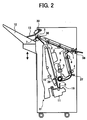
- FIG. 2 shows a sheet finisher embodying the present invention;
- FIG. 3 is an isometric view showing a jogging mechanism included in the illustrative embodiment;
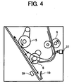
- FIG. 4 is a fragmentary view showing a return roller and members around it;
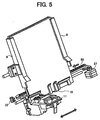
- FIG. 5 is an isometric view showing a stapler also included in the illustrative embodiment;
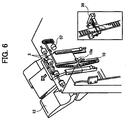
- FIG. 6 is a fragmentary isometric view showing a copy tray further included in the illustrative embodiment and arrangements around it;
- FIG. 7 is a schematic block diagram showing a control system of the illustrative embodiment;
- FIG. 8 is a flowchart demonstrating a
procedure 1 available with the illustrative embodiment; - FIG. 9 shows a relation between a first to a third position and the amount of pressing; and
- FIG. 10 is a flowchart showing a
procedure 2 also available with the illustrative embodiment. -
- To better understand the present invention, the problem with the sheet finisher taught in Japanese Patent No. 2,960,770 mentioned earlier will be described more specifically with reference to FIGS. 1A and 1B. In the event of stapling a large number of sheets, the jogging means included in the finisher again moves after the last jogging movement so as to press the sheets during stapling. This desirably enhances accurate jogging during stapling, as stated earlier. However, when the number of sheets to be stapled together is small, the sheets are loosened and therefore bent. As a result, the sheets stacked together are apt to shift in the lengthwise direction, which is perpendicular to the direction in which the jogging means moves.
- More specifically, FIG. 1 shows a stack of sheets accurately jogged by pressing members included in the jogging means. As shown in FIG. 1B, when the pressing members are fed toward such a jogged sheet stack by an excessive amount, the sheet stack bends in a semicylindrical cross-section. Further, the sheets tend to move away from a staple stray (upward in FIG. 1B) because they are restricted by the pressing members at the side edges and restricted by a rear fence at the rear edge. Moreover, if the amount by which the pressing members press the sheet stack is constant, then the ratio of the amount to width varies in accordance with sheet size, effecting the influence on jogging accuracy.
- Referring to FIG. 2, a finisher embodying the present invention is shown and operatively connected to a copier or similar image forming apparatus not shown. As shown, the finisher includes a sheet inlet for receiving sheets sequentially driven out of the copier. An
inlet sensor 36 and aninlet roller 1 adjoin the sheet inlet. Theinlet sensor 36 senses a sheet entering the finisher via the sheet inlet while theinlet roller 1 conveys the sheet into the finisher.Apath selector 8 steers the sheet toward either one of acopy tray 12 and astapler 11. -
Upper rollers 2 are positioned on the path extending from thepath selector 8 toward thecopy tray 12 so as to convey the sheet toward thetray 12. Anoutlet sensor 38 is responsive to the sheet being conveyed by theupper rollers 2. Anoutlet roller 3 drives the sheet out of the finisher to thecopy tray 12. Apush roller 7 pushes the sheet driven out to thecopy tray 12 to a preselected position. Alever 13 senses the sheet present on thecopy tray 12. Asheet level sensor 13 senses the angular position of thelever 13. An elevation motor 51 (see FIG. 7) selectively moves thecopy tray 12 upward or downward. Also, a shift motor 52 (see FIG. 7) moves thecopy tray 12 in the direction perpendicular to the direction of sheet conveyance, as needed. -
Lower rollers 4 are positioned on the path extending from thepath selector 8 toward thestapler 11 so as to convey the sheet toward thestapler 11. Asheet sensor 37 senses the sheet being conveyed by thelower rollers 4. A brush roller or feedroller 6 conveys the sheet moved away from thesheet sensor 37 into thestapler 11. A conveyance motor 54 (see FIG. 7) drives thelower rollers 4. - The
stapler 11 is positioned at the bottom of astapling section 61 and driven by a staple motor 56 (see FIG. 7), which will be described later. The staplingsection 61 additionally includes jogger fences 9 (only one is visible), a return roller or hitroller 5, and abelt 10. Thejogger fences 9 cooperate to jog the sheet driven onto a staple tray included in thestapling section 61. Thebelt 10 is positioned at the back of thejogger fences 9 for conveying a stapled sheet stack out of thestapling section 61. A belthome position sensor 39 adjoins thebelt 10 and is responsive to the home position of thebelt 10. Acatch 10a (see FIG. 6) is positioned on thebelt 10 for catching the sheet stack. Thesheet sensor 37 is located at such a position that even when thereturn roller 5 is caused to act just after thesensor 37 has sensed the trailing edge of the sheet, theroller 5 can hit the trailing edge of the sheet. - More specifically, as shown in FIG. 3, a
jogger motor 26 drives thejogger fences 9 via abelt 49. Asolenoid 30 supports thereturn roller 5 such that theroller 5 can swing in a pendulum fashion. Abelt 47 transmits the rotation of theconveyance motor 54 to one of rollers constituting eachlower rollers 4 and feedroller 6. As shown in FIG. 4, arear fence 19 is positioned below thejogger fences 9 such that the sheet abuts against therear fence 19. More specifically, as shown in FIG. 5, a pair ofrear fences 19 are positioned side by side. - As shown in FIG. 5, a
stapler motor 27 causes thestapler 11 to move via abelt 50 in a direction perpendicular to the direction of sheet conveyance, as indicated by a double-headed arrow. As shown in FIG. 6,belt motor 57 causes thebelt 10 to turn in a direction indicated by an arrow. A staplerhome position sensor 22 is responsive to the home position of thestapler 11. - FIG. 7 shows a control system included in the illustrative embodiment. As shown, the control system includes a CPU (Central Processing Unit) 70 implemented by, e.g., a microcomputer. Various switches and sensors arranged in the finisher send their outputs to the
CPU 70 via an I/O (Input/Output)interface 60. TheCPU 70 controls theconveyance motor 54 assigned to theinlet roller 1,upper rollers 2,lower rollers 4 and returnroller 5, adischarge motor 55 assigned to theoutlet roller 3 and pushroller 7, thejogger motor 26 assigned to thejogger fences 9, thestapler motor 27 assigned to thestapler 11, and thebelt motor 57 assigned to thebelt 10 in accordance with the outputs of the switches and sensors. Such motors all are implemented as stepping motors. - Further, the
CPU 70 controls, based on the outputs of the switches and sensors, a tray up-downmotor 51 and ashift motor 52 that are assigned to thecopy tray 12 as well as thestaple motor 56. Themotors CPU 70 sends a control signal to asolenoid 53 that actuates thepath selector 8. Counting pulses output from theconveyance motor 54, theCPU 70 controls asolenoid 30 assigned to thereturn roller 5 in accordance with the number of input pulses. TheCPU 70 constitutes positioning control means together with various operation programs for operating theCPU 70. - The operation of the illustrative embodiment will be described hereinafter. First, assume that the operator of the copier selects a non-staple mode. Then, the
solenoid 53 switches the position of thepath selector 8 for steering sheets toward theupper rollers 2. In this condition, theinlet roller 1 drives a sheet or copy driven out of the copier to theupper rollers 2 via thepath selector 8. The sheet is then sequentially driven by theupper rollers 2 andoutlet roller 3 to thecopy tray 12. Thepush roller 7 positions the sheet to be stacked on thecopy tray 12 in the direction of sheet conveyance. At this instant, as soon as thesheet sensor 38 senses the trailing edge of the sheet, thepush roller 7 is decelerated in order to enhance accurate stacking. As sheets are sequentially stacked on thecopy tray 12, the top of the sheet stack raises one end of thelever 13. When thesheet level sensor 33 senses the other end of thelever 13, the tray up-downmotor 51 is driven to lower thecopy tray 12 by a preselected amount. As a result, the top of the sheet stack on thecopy tray 12 is held at an adequate level at all times. - Assume that the operator selects a sort mode or a stack mode on a control panel mounted on the copier. Then, the
shift motor 52 repeatedly shifts thecopy tray 12 in the direction perpendicular to the direction of sheet conveyance, thereby sorting or stacking consecutive sheets until the job ends. At the end of the job, thecopy tray 12 is lowered by about 30 mm. - A staple mode unique to the illustrative embodiment will be described with reference to FIGS. 3 and 9. As shown in FIG. 9, each
jogger fence 9 is moved away from its home position to afirst position 7 mm remote from one side of a sheet width and waits for a sheet there ([I]). Theconveyance motor 54 drives thelower rollers 4 to thereby convey a sheet entered the finisher. As soon as the trailing edge of the sheet moves away from thesheet sensor 37, thejogger fence 9jogs 5 mm inward from the first position (stand-by position), as indicated by an arrow ([II]). On sensing the trailing edge of the sheet, thesheet sensor 37 sends its output to theCPU 70. In response, theCPU 70 starts counting pulses output from theconveyance motor 54. On counting a preselected number of pulses, theCPU 70 turns on thesolenoid 30. Thereturn roller 5 swings in a pendulum fashion in accordance with the turn-on and turn-off of thesolenoid 30. More specifically, when thesolenoid 30 is turned on, thereturn roller 5 hits the sheet to thereby return it downward until the sheet abuts against therear fences 19, thereby positioning the sheet in the longitudinal direction. Every time the inlet sensor 36 (or the sheet sensor 37) senses a sheet entered the finisher, theCPU 70 counts the sheet. - On the elapse of a preselected period of time since the turn-off of the
solenoid 30, thejogger motor 26 causes thejogger fence 9 to move 2.6 mm inward to a second position, as indicated by an arrow in FIG. 9, and stop there ([III]). As a result, the sheet is positioned in the lateral direction. Subsequently, thejogger fence 9 is returned from the second position to the first position by 7.6 mm so as to wait for the next sheet, as indicated by an arrow in FIG. 9 ([IV]). Thejogger fence 9 repeats such a movement up to the last sheet. When the last sheet is introduced into the staplingsection 61, thejogger fence 9 moves 2.6 mm inward to the second position, as indicated by an arrow in FIG. 9, and stops there ( [V] ) . Subsequently, thejogger fence 9 again moves 2.6 mm outward, as indicated by an arrow in FIG. 9 ([VI]), and then moves 2.2 mm inward to a third position, as indicated by an arrow in FIG. 9 ([VII]). Consequently, thejogger fences 9 press the opposite side edges of the sheet stack at the third position for thereby preparing the sheet stack for stapling. In FIG. 9, assume that thejogger fences 9 are spaced from each other by a distance of L2 at the second position or by a distance of L3 at the third position - FIG. 8 demonstrates a
procedure 1 for determining the amount of pressing. As shown, the third position is set in accordance with the width of sheets, as. measured in the direction perpendicular to the direction of sheet conveyance and the number of sheets to be stapled together. Also, a service person can change the third position on numeral keys arranged on the copier, as needed. After the jogging of the last sheet, theCPU 70 determines whether or not the width of the sheets is greater than B4T (B4 profile) (step 101). If the answer of thestep 101 is YES, then theCPU 70 determines whether or not the number of sheets to be stapled together is greater than thirty (step 102). If the answer of thestep 102 is YES, then theCPU 70 causes eachjogger fence 9 to move 2.6 mm (7.6 mm inward from the first position), i.e., to press the edge of the sheet stack by 0.6 mm (step 103). On the other hand, if the answer of thestep CPU 70 causes thejogger fence 9 to move 2.2 mm (7.2 mm inward from the first position), i.e., to press the edge of the sheet stack by 0.2 mm (step 104). - It should be noted that the specific numerical values stated above are not theoretical values, but are simply typical values. While the illustrative embodiment varies the third position, the second position may be varied, in which case the third position will be varied relative to the second position.
- On the elapse of a preselected period of time, the
stapler 11 is driven to staple the stack of sheets. Assume that the operator selects a mode for stapling the sheet stack at a plurality of positions. Then, after stapling the sheet stack at one position, thestapler 11 is moved to another stapling position along the trailing edge of the sheet stack and again staples the sheet stack. After the stapling operation, thebelt motor 57 is energized to drive thebelt 10. At the same time or on the elapse of a preselected period of time, thedischarge motor 55 is energized in order to receive the sheet stack raised by thecatch 10a of thebelt 10. - The
jogger fences 9 are controlled in accordance with the sheet size and the number of sheets stapled together. For example, assume that the number of sheets is smaller than preselected one (thirty in the illustrative embodiment) or that the sheet size is smaller than preselected one (B4T in the illustrative embodiment). Then, thejogger fences 9 press the sheet stack whose trailing edge is raised by thecatch 10a. When a preselected number of pulses are output after the belthome position sensor 39 has sensed the home position of thebelt 10, thejogger fences 9 each are retracted by a preselected distance so as to release the sheet stack. The number of the above pulses corresponds to an interval between the time when thecatch 10a abuts against the trailing edge of the sheet stack and the time when it moves away from the ends of thejogger fences 9. When the number of sheets is greater than preselected one or when the sheet size is greater than preselected one, thejogger fences 9 are retracted by the preselected distance beforehand. - In any case, as soon as the sheet stack moves away from the
jogger fences 9, thejogger fences 9 are again moved to the first position or stand-by position to prepare for the next sheet. The procedure described above is repeated up to the last job. - In the illustrative embodiment, each
jogger fence 9 presses the sheets by 0.6 mm up to the last sheet. It is sometimes preferable to control the amount of pressing before the last page also, depending on the sheet size and the number of sheets to be stapled together. FIG. 10 shows aprocedure 2 for determining the amount of pressing. As shown, assume that the sheet width is smaller than B4T (NO, step 201) or that the sheet width is greater than B4T (YES, step 201), but the number of sheets to be stapled together is less than thirty (NO, step 202). Then, thejogger fences 9 press the sheets preceding the last sheet by 0.6 mm (step 204). If the answers of thesteps jogger fences 9 press the sheet stack by an amount greater than 0.6 mm, e.g., 0.8 mm to 1.0 mm (step 203). In the illustrative embodiment, thejogger fences 9 have a generally L-shaped cross-section each. Therefore, even when the number of sheets is great and causes the sheet stack to bend relative to the staple tray, thejogger fences 9 prevent the sheet stack from dropping from the staple tray. - In summary, in accordance with the present invention, a sheet finisher allows the second and third positions to be adequately set in accordance with the sheet size and the number of sheets to be stapled together. The finisher can therefore accurately jog sheets without regard to the sheet size. Further, the finisher allows a sheet stack to be surely stapled while guaranteeing high-quality jogging.
- Various modifications will become possible for those skilled in the art after receiving the teachings of the present disclosure without departing from the scope thereof.
- In accordance with the invention, a sheet finisher of the present invention includes jogger fences for jogging sheets sequentially stacked in a stapling section, and a stapler for stapling the sheets together. Preferably, CPU (Central Processing Unit) controls a jogger motor such that the jogger fences each move to a first position, a second position, and a third position in accordance with the width of sheets in a direction perpendicular to the direction of sheet conveyance. Preferably, the first position is remote from the edge of a sheet stack in the direction of the width by a preselected amount. Preferably, the second position is closer to the edge than the first position by a preselected amount and preferably slightly overlaps the edge. At the third position, when the stapler staples the sheet stack, the jogger fence preferably substantially contacts the edge in accordance with the width.
- The processing means executes preferably a finishing processing with the stack of sheets. Preferably, the finishing processing is stapling, binding, and/or punching.
- In the first position, the distance between both jogging members is preferably greater than the width of the sheets to be jogged. In the second position, the distance between the jogging members is preferably smaller than the width of the sheets to be jogged. In the third position, the distance between the jogging members is preferably greater than in the second position but still smaller than or about equal to the width of the sheets to be jogged. Preferably, the distance between the two jogging members is more than 80% or 90% of the width of the sheets to be jogged in the second position.
- Preferably, the second position is chosen in case of the stack of sheets is not yet complete and at least one further sheet will be fed to the stack of sheets. Preferably, the third position is chosen if the last sheet to be stacked has already been fed to the stack of sheets.
- Preferably, the distances are chosen in dependence on characteristics of the sheets or of the stack, in particular in accordance with mechanical and/or physical properties thereof which have an influence on an undesired displacement of the sheets during the jogging. Those characteristics are in particular the width, the thickness, the elasticity, and/or the material of the sheets and/or of the stack.
Claims (6)
- A sheet finisher comprising:wherein assuming that said pair of jogging members are spaced from each other by a distance of L2 at said second position or by a distance of L3 at said third position, said control means sets at least one of said distances L2 and L3 in accordance with one or more characteristics of the sheets to be jogged and/or of the stack of sheets, said one or more characteristics being in particular at least one of the following: the number of sheets to be jogged, the width of the sheets to be jogged, the thickness of the sheets to be jogged, the elasticity of the sheets to be jogged and/or of the stack, and/or the material of the sheets to be jogged.stacking means for stacking sheets thereon;jogging means for jogging the sheets sequentially stacked on said stacking means one by one; andprocessing means for executing preselected processing with the sheets;said jogging means comprising:a pair of jogging members for jogging the sheets one by one; andcontrol means for moving, in accordance with a width of the sheets in a direction perpendicular to a direction of sheet conveyance, each of said pair of jogging members to a first position remote from an edge of said sheets in a direction of the width by a preselected amount, a second position closer to said edge than said first position by a preselected amount and slightly overlapping said edge, and a third position where, when said processing means executes the preselected processing, said jogging member substantially contacts said edge in accordance with said width;
- The sheet finisher as claimed in claim 1, wherein the preselected processing comprises at least one of stapling, binding and/or punching.
- The sheet finisher as claimed in claim 1 or 2, wherein the distance L2 is smaller than or equal to the distance L3.
- An image forming system comprising:a sheet finisher according to one of claims 1 to 3; andan image forming apparatus for forming a toner image on a sheet.
- The system as claimed in claim 4, further comprising varying means for varying the distance L2 or L3.
- The system as claimed in claim 5, wherein said varying means is included in said image forming apparatus or in said sheet finisher.
Applications Claiming Priority (4)
| Application Number | Priority Date | Filing Date | Title |
|---|---|---|---|
| JP2001112815 | 2001-04-11 | ||
| JP2001112815 | 2001-04-11 | ||
| JP2002086718 | 2002-03-26 | ||
| JP2002086718A JP2002370864A (en) | 2001-04-11 | 2002-03-26 | Paper handling equipment |
Publications (2)
| Publication Number | Publication Date |
|---|---|
| EP1249419A1 true EP1249419A1 (en) | 2002-10-16 |
| EP1249419B1 EP1249419B1 (en) | 2004-09-22 |
Family
ID=26613437
Family Applications (1)
| Application Number | Title | Priority Date | Filing Date |
|---|---|---|---|
| EP02007398A Expired - Lifetime EP1249419B1 (en) | 2001-04-11 | 2002-04-10 | Sheet finisher for an image forming apparatus |
Country Status (4)
| Country | Link |
|---|---|
| US (1) | US6698744B2 (en) |
| EP (1) | EP1249419B1 (en) |
| JP (1) | JP2002370864A (en) |
| DE (1) | DE60201289T2 (en) |
Families Citing this family (80)
| Publication number | Priority date | Publication date | Assignee | Title |
|---|---|---|---|---|
| JP4769420B2 (en) * | 2003-04-09 | 2011-09-07 | 株式会社リコー | Image forming apparatus |
| US7172185B2 (en) | 2003-05-23 | 2007-02-06 | Ricoh Company, Ltd. | Sheet punch device, sheet processing device, image forming system, program, and recording medium |
| JP4088206B2 (en) * | 2003-06-12 | 2008-05-21 | 株式会社リコー | Paper folding device, paper processing device, and image forming system |
| JP4340582B2 (en) * | 2003-07-28 | 2009-10-07 | 株式会社リコー | Paper processing apparatus and image forming apparatus |
| JP2005066816A (en) * | 2003-08-01 | 2005-03-17 | Ricoh Co Ltd | Punching device, paper processing device, and image forming device |
| JP4106001B2 (en) * | 2003-08-29 | 2008-06-25 | 株式会社リコー | Paper transport device, paper processing device, image forming device, image forming system, and computer program |
| JP2005112630A (en) * | 2003-09-17 | 2005-04-28 | Ricoh Co Ltd | Sheet conveying apparatus and image forming apparatus, image reading apparatus, and post-processing apparatus including the same |
| JP4401978B2 (en) | 2004-02-20 | 2010-01-20 | キヤノン株式会社 | Sheet processing apparatus and image forming apparatus |
| JP4446880B2 (en) * | 2004-03-17 | 2010-04-07 | 株式会社リコー | Paper processing apparatus and image forming system |
| JP4933052B2 (en) * | 2004-03-18 | 2012-05-16 | オセ−テクノロジーズ ビーブイ | Sheet processing method and sheet processing apparatus for smart punching |
| JP2006082938A (en) * | 2004-09-16 | 2006-03-30 | Canon Inc | Sheet conveying apparatus and image forming apparatus provided with the apparatus |
| US7416177B2 (en) * | 2004-09-16 | 2008-08-26 | Ricoh Company, Ltd. | Sheet folding apparatus, sheet processing apparatus and image forming apparatus |
| JP2006096466A (en) * | 2004-09-28 | 2006-04-13 | Toshiba Tec Corp | Sheet post-processing device |
| JP4164058B2 (en) * | 2004-09-28 | 2008-10-08 | 東芝テック株式会社 | Sheet post-processing apparatus and standby tray |
| JP2006096444A (en) * | 2004-09-28 | 2006-04-13 | Toshiba Tec Corp | Sheet post-treatment device |
| US7300045B2 (en) * | 2004-09-28 | 2007-11-27 | Toshiba Tec Kabushiki Kaisha | Waiting tray for sheet processing tray |
| JP2006096464A (en) * | 2004-09-28 | 2006-04-13 | Toshiba Tec Corp | Sheet post-processing device |
| JP2006096454A (en) * | 2004-09-28 | 2006-04-13 | Toshiba Tec Corp | Sheet post-processing device |
| JP4471207B2 (en) * | 2004-09-28 | 2010-06-02 | 東芝テック株式会社 | Sheet post-processing device |
| JP2006096443A (en) * | 2004-09-28 | 2006-04-13 | Toshiba Tec Corp | Sheet post-processing device |
| JP2006096459A (en) * | 2004-09-28 | 2006-04-13 | Toshiba Tec Corp | Sheet post-processing device |
| JP2006096468A (en) * | 2004-09-28 | 2006-04-13 | Toshiba Tec Corp | Sheet post-processing device |
| JP4018683B2 (en) * | 2004-09-28 | 2007-12-05 | 東芝テック株式会社 | Sheet post-processing apparatus and standby tray |
| JP2006096470A (en) * | 2004-09-28 | 2006-04-13 | Toshiba Tec Corp | Sheet post-processing device |
| JP4021888B2 (en) * | 2004-09-28 | 2007-12-12 | 東芝テック株式会社 | Sheet post-processing device |
| JP4057574B2 (en) * | 2004-09-28 | 2008-03-05 | 東芝テック株式会社 | Sheet post-processing apparatus and standby tray |
| JP2006096461A (en) * | 2004-09-28 | 2006-04-13 | Toshiba Tec Corp | Sheet post-processing device |
| JP4250132B2 (en) * | 2004-09-28 | 2009-04-08 | 東芝テック株式会社 | Sheet post-processing apparatus and standby tray |
| JP4280220B2 (en) * | 2004-09-28 | 2009-06-17 | 東芝テック株式会社 | Sheet post-processing apparatus and standby tray |
| JP4291243B2 (en) * | 2004-09-28 | 2009-07-08 | 東芝テック株式会社 | Sheet post-processing device |
| JP2006096447A (en) * | 2004-09-28 | 2006-04-13 | Toshiba Tec Corp | Sheet post-processing apparatus and standby tray |
| JP2006096453A (en) * | 2004-09-28 | 2006-04-13 | Toshiba Tec Corp | Sheet post-processing apparatus and processing tray |
| JP4293446B2 (en) * | 2004-09-28 | 2009-07-08 | 東芝テック株式会社 | Sheet post-processing device |
| JP4034300B2 (en) * | 2004-09-28 | 2008-01-16 | 東芝テック株式会社 | Sheet post-processing apparatus and standby tray |
| JP4297361B2 (en) * | 2004-09-28 | 2009-07-15 | 東芝テック株式会社 | Sheet post-processing device |
| JP2006096451A (en) * | 2004-09-28 | 2006-04-13 | Toshiba Tec Corp | Sheet post-processing apparatus and standby tray |
| JP4057575B2 (en) * | 2004-09-28 | 2008-03-05 | 東芝テック株式会社 | Sheet post-processing device |
| JP2006096467A (en) * | 2004-09-28 | 2006-04-13 | Toshiba Tec Corp | Sheet post-processing device |
| JP2006124171A (en) * | 2004-09-29 | 2006-05-18 | Toshiba Tec Corp | Paper post-processing device |
| JP2006124170A (en) * | 2004-09-29 | 2006-05-18 | Toshiba Tec Corp | Paper post-processing device |
| JP4034307B2 (en) * | 2004-09-29 | 2008-01-16 | 東芝テック株式会社 | Paper post-processing device |
| JP2006124154A (en) * | 2004-09-29 | 2006-05-18 | Toshiba Tec Corp | Paper post-processing device |
| JP2006124164A (en) * | 2004-09-29 | 2006-05-18 | Toshiba Tec Corp | Paper post-processing device |
| JP4315343B2 (en) * | 2004-09-29 | 2009-08-19 | 東芝テック株式会社 | Paper post-processing device |
| JP4034306B2 (en) * | 2004-09-29 | 2008-01-16 | 東芝テック株式会社 | Sheet post-processing device |
| JP2006124166A (en) * | 2004-09-29 | 2006-05-18 | Toshiba Tec Corp | Paper post-processing device |
| JP2006124169A (en) * | 2004-09-29 | 2006-05-18 | Toshiba Tec Corp | Paper post-processing device |
| JP2006124173A (en) * | 2004-09-29 | 2006-05-18 | Toshiba Tec Corp | Paper post-processing device |
| JP4748993B2 (en) * | 2004-10-21 | 2011-08-17 | 株式会社リコー | Sheet stacking apparatus and image forming apparatus |
| JP4459879B2 (en) * | 2004-11-11 | 2010-04-28 | 株式会社リコー | Paper punching device, paper post-processing device including the same, and image forming apparatus |
| US7413181B2 (en) * | 2004-11-15 | 2008-08-19 | Ricoh Company Ltd. | Method and apparatus for image forming capable of effectively performing sheet finishing operation |
| US7407156B2 (en) | 2005-03-22 | 2008-08-05 | Toshiba Tec Kabushiki Kaisha | Sheet finishing apparatus |
| US20060214343A1 (en) * | 2005-03-22 | 2006-09-28 | Toshiba Tec Kabushiki Kaisha | Sheet finishing apparatus |
| US7328894B2 (en) * | 2005-03-22 | 2008-02-12 | Toshiba Tec Kabushiki Kaisha | Sheet finishing apparatus |
| US20060214346A1 (en) * | 2005-03-22 | 2006-09-28 | Toshiba Tec Kabushiki Kaisha | Sheet finishing apparatus |
| US7364149B2 (en) * | 2005-03-22 | 2008-04-29 | Toshiba Tec Kabushiki Kaisha | Sheet finishing apparatus |
| JP4695526B2 (en) * | 2005-05-20 | 2011-06-08 | 株式会社リコー | Paper conveying apparatus and image forming apparatus |
| US7909524B2 (en) * | 2005-06-30 | 2011-03-22 | Lexmark International, Inc. | Folding edge guide assembly for an imaging apparatus |
| JP2007022745A (en) * | 2005-07-15 | 2007-02-01 | Konica Minolta Business Technologies Inc | Paper aligning device, and paper post-processing device |
| US7537206B2 (en) * | 2005-09-15 | 2009-05-26 | Kabushiki Kaisha Toshiba | Sheet alignment apparatus and sheet post-processing apparatus |
| EP1785776B1 (en) * | 2005-11-09 | 2011-01-05 | Konica Minolta Business Technologies, Inc. | Image forming apparatus and unit for sheet pile forming and conveyance |
| JP4495079B2 (en) * | 2005-12-26 | 2010-06-30 | 東芝テック株式会社 | Paper post-processing device |
| JP4777839B2 (en) * | 2006-07-07 | 2011-09-21 | 株式会社リコー | Sheet alignment apparatus, sheet processing apparatus, and image forming apparatus |
| JP4814156B2 (en) * | 2006-08-11 | 2011-11-16 | 株式会社リコー | Sheet alignment mechanism, sheet post-processing apparatus, and image forming apparatus |
| JP2008063063A (en) * | 2006-09-06 | 2008-03-21 | Ricoh Co Ltd | Sheet alignment apparatus, sheet processing apparatus, and image forming apparatus |
| US7862025B2 (en) * | 2007-03-02 | 2011-01-04 | Toshiba Tec Kabushiki Kaisha | Sheet post-processing apparatus |
| JP4353284B2 (en) * | 2007-06-20 | 2009-10-28 | 船井電機株式会社 | Paper feeding mechanism and image forming apparatus |
| US8006971B2 (en) * | 2007-09-11 | 2011-08-30 | Kabushiki Kaisha Toshiba | Sheet stack apparatus and sheet stacking method |
| JP2009067594A (en) * | 2007-09-11 | 2009-04-02 | Toshiba Corp | Paper loading device and paper loading method |
| JP4929124B2 (en) * | 2007-10-30 | 2012-05-09 | 株式会社リコー | Sheet alignment apparatus, sheet processing apparatus, and image forming apparatus |
| JP2009166971A (en) * | 2008-01-17 | 2009-07-30 | Sharp Corp | Post-processing apparatus and image forming apparatus |
| JP2009227464A (en) | 2008-02-28 | 2009-10-08 | Ricoh Co Ltd | Sheet post-processing device and image forming device |
| JP5146059B2 (en) * | 2008-04-01 | 2013-02-20 | 富士ゼロックス株式会社 | Recording material storage device, recording material post-processing device using the same, and recording material processing device |
| JP5369698B2 (en) * | 2008-04-04 | 2013-12-18 | 株式会社リコー | Image forming system |
| US7984900B2 (en) * | 2008-07-17 | 2011-07-26 | Kabushiki Kaisha Toshiba | Bundle hook discharge device |
| US8733753B2 (en) * | 2010-07-28 | 2014-05-27 | Kabushiki Kaisha Toshiba | Sheet processing device |
| JP6004801B2 (en) * | 2011-07-29 | 2016-10-12 | キヤノン株式会社 | Sheet stacking apparatus and image forming apparatus |
| JP5858332B2 (en) * | 2011-10-13 | 2016-02-10 | 株式会社リコー | Paper processing apparatus and image forming apparatus |
| JP5857635B2 (en) * | 2011-10-31 | 2016-02-10 | 株式会社リコー | Post-processing apparatus, image forming apparatus, and image forming system |
| JP6229394B2 (en) * | 2013-09-19 | 2017-11-15 | コニカミノルタ株式会社 | Paper processing apparatus and image forming system |
Citations (2)
| Publication number | Priority date | Publication date | Assignee | Title |
|---|---|---|---|---|
| US5072920A (en) * | 1989-09-12 | 1991-12-17 | Ricoh Company, Ltd. | Finisher for an image forming apparatus |
| US5622359A (en) * | 1994-12-14 | 1997-04-22 | Konica Corporation | Sheet finishing apparatus |
Family Cites Families (16)
| Publication number | Priority date | Publication date | Assignee | Title |
|---|---|---|---|---|
| US5692411A (en) | 1984-11-17 | 1997-12-02 | Ricoh Co., Ltd. | Quiet paper sorter using a collision impact reduction means |
| US5263697A (en) * | 1989-04-18 | 1993-11-23 | Ricoh Company, Ltd. | Finisher for an image forming apparatus |
| JP2549757Y2 (en) * | 1989-12-13 | 1997-09-30 | 株式会社リコー | Image formation post-processing device |
| JP3359662B2 (en) | 1992-08-19 | 2002-12-24 | 株式会社リコー | Image forming system device |
| US5634634A (en) * | 1995-03-06 | 1997-06-03 | Eastman Kodak Company | Vacuum corrugated duplex tray having oscillating side guides |
| JP3466376B2 (en) * | 1995-06-07 | 2003-11-10 | 株式会社リコー | Paper post-processing equipment |
| DE19719485C2 (en) | 1996-05-08 | 2003-03-20 | Ricoh Kk | Document handling device with a staple mode |
| JP3748710B2 (en) | 1997-06-10 | 2006-02-22 | 株式会社リコー | Sheet processing device |
| US6494449B2 (en) | 1997-12-01 | 2002-12-17 | Ricoh Company, Ltd. | Sheet stacking apparatus with vertically movable tray |
| US6296247B1 (en) * | 1997-12-01 | 2001-10-02 | Ricoh Company, Ltd. | Sheet stacking apparatus with vertically movable tray |
| US6231045B1 (en) | 1998-06-12 | 2001-05-15 | Ricoh Company, Ltd. | Finisher for an image forming apparatus |
| JP3844177B2 (en) | 1998-07-31 | 2006-11-08 | 株式会社リコー | Paper discharge device |
| JP3898367B2 (en) | 1998-12-25 | 2007-03-28 | 株式会社リコー | Paper post-processing device |
| US6382616B1 (en) * | 1999-01-19 | 2002-05-07 | Canon Kabushiki Kaisha | Aligning device for sheet finisher |
| JP3748754B2 (en) | 1999-03-23 | 2006-02-22 | 株式会社リコー | Paper processing device |
| JP3973828B2 (en) | 1999-10-08 | 2007-09-12 | 株式会社リコー | Paper loading device |
-
2002
- 2002-03-26 JP JP2002086718A patent/JP2002370864A/en active Pending
- 2002-04-10 EP EP02007398A patent/EP1249419B1/en not_active Expired - Lifetime
- 2002-04-10 DE DE60201289T patent/DE60201289T2/en not_active Expired - Lifetime
- 2002-04-10 US US10/118,956 patent/US6698744B2/en not_active Expired - Lifetime
Patent Citations (2)
| Publication number | Priority date | Publication date | Assignee | Title |
|---|---|---|---|---|
| US5072920A (en) * | 1989-09-12 | 1991-12-17 | Ricoh Company, Ltd. | Finisher for an image forming apparatus |
| US5622359A (en) * | 1994-12-14 | 1997-04-22 | Konica Corporation | Sheet finishing apparatus |
Also Published As
| Publication number | Publication date |
|---|---|
| US6698744B2 (en) | 2004-03-02 |
| DE60201289T2 (en) | 2006-02-23 |
| JP2002370864A (en) | 2002-12-24 |
| EP1249419B1 (en) | 2004-09-22 |
| DE60201289D1 (en) | 2004-10-28 |
| US20020163120A1 (en) | 2002-11-07 |
Similar Documents
| Publication | Publication Date | Title |
|---|---|---|
| EP1249419B1 (en) | Sheet finisher for an image forming apparatus | |
| US5762328A (en) | Subsequent paper treatment apparatus | |
| EP2465797B1 (en) | Sheet processing apparatus, image forming system, and sheet processing method | |
| KR100262915B1 (en) | Paper finishing device | |
| US7326167B2 (en) | Sheet folding device | |
| US7014183B2 (en) | Sheet-shaped medium treatment apparatus | |
| JP4880575B2 (en) | Paper post-processing device | |
| CN101254875B (en) | Paper handling device | |
| EP2520527B1 (en) | Sheet handling apparatus, image forming system, and sheet reception control method | |
| JP5741384B2 (en) | Sheet processing apparatus, image forming system, and sheet processing method | |
| US7487964B2 (en) | Sheet finisher for an image forming apparatus | |
| US20150108712A1 (en) | Sheet stacking apparatus and sheet processing apparatus as well as image forming apparatus | |
| US7377511B2 (en) | Sheet stacking apparatus | |
| JP3579589B2 (en) | Staple device | |
| US5374043A (en) | Sorter with stapler actived release gate mechanism | |
| JPH1160026A (en) | Sheet alignment device | |
| US6547230B2 (en) | Stapler with variable staple english | |
| JP2012126515A (en) | Sheet processing apparatus, image forming system, and sheet processing method | |
| JPH0826569A (en) | Paper post-processing device | |
| JP3258726B2 (en) | Recording paper receiving device | |
| JPH1059610A (en) | Paper post-processing equipment | |
| JP3602930B2 (en) | Paper post-processing equipment | |
| JP3527804B2 (en) | Paper post-processing equipment | |
| JP2002020025A (en) | Paper handling equipment | |
| JP2000063033A (en) | Paper post-processing equipment |
Legal Events
| Date | Code | Title | Description |
|---|---|---|---|
| PUAI | Public reference made under article 153(3) epc to a published international application that has entered the european phase |
Free format text: ORIGINAL CODE: 0009012 |
|
| 17P | Request for examination filed |
Effective date: 20020410 |
|
| AK | Designated contracting states |
Kind code of ref document: A1 Designated state(s): AT BE CH CY DE DK ES FI FR GB GR IE IT LI LU MC NL PT SE TR |
|
| AX | Request for extension of the european patent |
Free format text: AL;LT;LV;MK;RO;SI |
|
| 17Q | First examination report despatched |
Effective date: 20030410 |
|
| AKX | Designation fees paid |
Designated state(s): DE FR GB |
|
| GRAP | Despatch of communication of intention to grant a patent |
Free format text: ORIGINAL CODE: EPIDOSNIGR1 |
|
| RIN1 | Information on inventor provided before grant (corrected) |
Inventor name: SUZUKI, NOBUYOSHI Inventor name: OKADA, HIROKI Inventor name: SAITOH, HIROMOTO Inventor name: ASAMI, SHINJI Inventor name: SASAKI, TAKESHI Inventor name: IIDA, JUNICHI Inventor name: YAMADA, KENJI |
|
| GRAS | Grant fee paid |
Free format text: ORIGINAL CODE: EPIDOSNIGR3 |
|
| GRAA | (expected) grant |
Free format text: ORIGINAL CODE: 0009210 |
|
| AK | Designated contracting states |
Kind code of ref document: B1 Designated state(s): DE FR GB |
|
| REG | Reference to a national code |
Ref country code: GB Ref legal event code: FG4D |
|
| REG | Reference to a national code |
Ref country code: IE Ref legal event code: FG4D |
|
| REF | Corresponds to: |
Ref document number: 60201289 Country of ref document: DE Date of ref document: 20041028 Kind code of ref document: P |
|
| PLBE | No opposition filed within time limit |
Free format text: ORIGINAL CODE: 0009261 |
|
| STAA | Information on the status of an ep patent application or granted ep patent |
Free format text: STATUS: NO OPPOSITION FILED WITHIN TIME LIMIT |
|
| ET | Fr: translation filed | ||
| 26N | No opposition filed |
Effective date: 20050623 |
|
| PGFP | Annual fee paid to national office [announced via postgrant information from national office to epo] |
Ref country code: DE Payment date: 20130419 Year of fee payment: 12 Ref country code: GB Payment date: 20130418 Year of fee payment: 12 |
|
| PGFP | Annual fee paid to national office [announced via postgrant information from national office to epo] |
Ref country code: FR Payment date: 20130515 Year of fee payment: 12 |
|
| REG | Reference to a national code |
Ref country code: DE Ref legal event code: R119 Ref document number: 60201289 Country of ref document: DE |
|
| GBPC | Gb: european patent ceased through non-payment of renewal fee |
Effective date: 20140410 |
|
| REG | Reference to a national code |
Ref country code: FR Ref legal event code: ST Effective date: 20141231 |
|
| REG | Reference to a national code |
Ref country code: DE Ref legal event code: R119 Ref document number: 60201289 Country of ref document: DE Effective date: 20141101 |
|
| PG25 | Lapsed in a contracting state [announced via postgrant information from national office to epo] |
Ref country code: GB Free format text: LAPSE BECAUSE OF NON-PAYMENT OF DUE FEES Effective date: 20140410 Ref country code: DE Free format text: LAPSE BECAUSE OF NON-PAYMENT OF DUE FEES Effective date: 20141101 |
|
| PG25 | Lapsed in a contracting state [announced via postgrant information from national office to epo] |
Ref country code: FR Free format text: LAPSE BECAUSE OF NON-PAYMENT OF DUE FEES Effective date: 20140430 |