EP1249374B1 - Airbag apparatus - Google Patents
Airbag apparatus Download PDFInfo
- Publication number
- EP1249374B1 EP1249374B1 EP02006526A EP02006526A EP1249374B1 EP 1249374 B1 EP1249374 B1 EP 1249374B1 EP 02006526 A EP02006526 A EP 02006526A EP 02006526 A EP02006526 A EP 02006526A EP 1249374 B1 EP1249374 B1 EP 1249374B1
- Authority
- EP
- European Patent Office
- Prior art keywords
- airbag
- folded
- container
- folding
- vehicle
- Prior art date
- Legal status (The legal status is an assumption and is not a legal conclusion. Google has not performed a legal analysis and makes no representation as to the accuracy of the status listed.)
- Expired - Lifetime
Links
- 238000000034 method Methods 0.000 claims description 18
- 230000003542 behavioural effect Effects 0.000 description 2
- 230000002093 peripheral effect Effects 0.000 description 2
- 230000003139 buffering effect Effects 0.000 description 1
- 230000001419 dependent effect Effects 0.000 description 1
- 230000000694 effects Effects 0.000 description 1
Images


Classifications
-
- B—PERFORMING OPERATIONS; TRANSPORTING
- B60—VEHICLES IN GENERAL
- B60R—VEHICLES, VEHICLE FITTINGS, OR VEHICLE PARTS, NOT OTHERWISE PROVIDED FOR
- B60R21/00—Arrangements or fittings on vehicles for protecting or preventing injuries to occupants or pedestrians in case of accidents or other traffic risks
- B60R21/02—Occupant safety arrangements or fittings, e.g. crash pads
- B60R21/16—Inflatable occupant restraints or confinements designed to inflate upon impact or impending impact, e.g. air bags
- B60R21/23—Inflatable members
- B60R21/237—Inflatable members characterised by the way they are folded
-
- B—PERFORMING OPERATIONS; TRANSPORTING
- B60—VEHICLES IN GENERAL
- B60R—VEHICLES, VEHICLE FITTINGS, OR VEHICLE PARTS, NOT OTHERWISE PROVIDED FOR
- B60R21/00—Arrangements or fittings on vehicles for protecting or preventing injuries to occupants or pedestrians in case of accidents or other traffic risks
- B60R21/02—Occupant safety arrangements or fittings, e.g. crash pads
- B60R21/16—Inflatable occupant restraints or confinements designed to inflate upon impact or impending impact, e.g. air bags
- B60R21/20—Arrangements for storing inflatable members in their non-use or deflated condition; Arrangement or mounting of air bag modules or components
- B60R21/217—Inflation fluid source retainers, e.g. reaction canisters; Connection of bags, covers, diffusers or inflation fluid sources therewith or together
- B60R21/2171—Inflation fluid source retainers, e.g. reaction canisters; Connection of bags, covers, diffusers or inflation fluid sources therewith or together specially adapted for elongated cylindrical or bottle-like inflators with a symmetry axis perpendicular to the main direction of bag deployment, e.g. extruded reaction canisters
Definitions
- the present invention relates to an airbag apparatus which is suitably used as a passenger- or driver-side airbag apparatus installed in front of an occupant in a vehicle such as an automobile.
- a passenger-side airbag apparatus comprises a container arranged in an instrument panel in front of a front passenger seat, a gas generator for inflating an airbag, the airbag which is folded and accommodated in the container, and a lid covering the container.
- the gas generator is actuated to supply gas into the airbag, whereby the airbag starts to inflate.
- the lid is pushed by the airbag to open so that the airbag inflates toward the vehicle cabin.
- the airbag is provided with a gas inlet for receiving gas from the gas generator.
- the peripheral edge of the gas inlet is connected to the container.
- the airbag is folded by a step of first reverse folding both left and right sides of the airbag toward the center, the airbag in this state being called as an interim folded body having a reduced lateral width, and a step of folding the interim folded body into a bellow, the airbag in this state being called as a lump body. Then, the lump body is accommodated in the container.
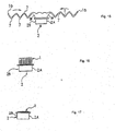
- Fig. 11 is a perspective view showing an airbag 1 spread in a plane and a sub container 2.
- the airbag 1 is an envelop-like object of which the shorter sides 1b are rectilinear and the right and left longer sides 1a are curved in arc-like shape.
- gas inlet 3 for receiving gas from an inflator.
- gas outlets (vent holes) 4 for buffering impact on the occupant when the occupant collides with the deployed (fully inflated) airbag.
- Numeral 5 designates rivet holes.
- the sub container 2 has a bottom face with holes 6 for passage of gas from the inflator.
- the airbag 1 is spread in a plane in a state that the sub container 2 is connected to the airbag 1. Then, as shown in Fig. 13 and Fig. 14 (sectional view taken along a line XIV-XIV of Fig. 13 ), portions along the longer sides 1a are folded inside the airbag 1 to make the width of the airbag 1 slightly smaller than the width of the sub container 2, so as to form an interim folded body.
- the interim folded body is repeatedly folded into a bellow to make valley and mountain folds 7 in directions perpendicular to the rectilinear longer sides 1a' of the interim folded body.
- Fig. 16 repeatedly folded portions are piled on each other to form a lump body and the lump body is accommodated in the sub container 2 ( Fig. 17 ).
- the folded airbag is accommodated in the sub container 2 and the sub container 2 with the airbag is accommodated in a main container (not shown).
- the sub container may be omitted and in this case, the folded airbag is directly accommodated in a container.
- the airbag 1 is folded so as to form the lump body.
- the peripheral edge of the gas inlet 3 of the airbag 1 is connected to the sub container 2.
- the area of the airbag 1 about the periphery of the gas inlet 3 is composed of two area: a windshield-side area 1A connected to a windshield side 2A of the sub container 2 and an occupant-side area 1B connected to the occupant-side 2B of the sub container 2, the windshield-side area 1A and the occupant-side area 1B are equal in length.
- the airbag 1 when the airbag 1 is inflated (deployed) by gas from the inflator, the airbag 1 is deployed such that a vehicle-front side portion i.e. the windshield side portion and a vehicle-rear side portion i.e. the occupant side portion of the airbag are substantially symmetrically inflated.
- a folded airbag is disclosed.
- the airbag is folded in such a manner that the front portion or upper end portion of the airbag is inflated earlier than a rear portion or bottom portion of the airbag.
- the smooth deployment of the airbag may be obtained by such a structure that the front portion (vehicle-front side portion) of the airbag is inflated earlier than the rear portion (vehicle-rear side portion) of the airbag, but of course, it depends on the layout of the cabin and the arrangement angle of the instrument panel of the vehicle and the arrangement of the airbag apparatus.
- An airbag apparatus of the present invention comprises a folded airbag and a gas generator for inflating the airbag, wherein the airbag is designed to be deployed in front of an occupant, where the airbag is folded such that a front portion thereof in the longitudinal direction of a vehicle is inflated earlier than a rear portion thereof.
- the rear portion of the airbag is first folded, then left and right portions are then folded, and after that, the front portion is folded, thereby ensuring that the front portion is inflated earlier than the rear portion in a process of deployment of the airbag.
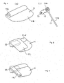
- Fig. 1(a) through Fig. 9 are illustrations for explaining a process of folding an airbag of a passenger-side airbag apparatus according to the embodiment.
- Figs. 1(a), 2(a), 3(a) , 4(a) and Figs. 5-8 are perspective views
- Figs. 1(b), 2(b), 3(b) , 4(b) are sectional views taken along line B-B of Figs. 1(a), 2(a), 3(a) , 4(a) , respectively
- Fig. 9 is a sectional view showing a state that the folded airbag is about to be assembled into a container.
- Figs. 10(a)-10(c) are illustration for explaining profiles of the inflating airbag.
- the passenger-side airbag apparatus 10 comprises an airbag 11, a container 12 accommodating the airbag 11, an inflator 13 which is attached to the container 12 for generating gas for inflating the airbag 11, and a lid (not shown) for covering an opening in the top of the container 12. As shown in Fig. 9 , the airbag 11 is secured around its gas inlet to the container 12 by a fastening member 14.
- the airbag 11 For folding and accommodating the airbag 11 into the container 12, the airbag 11 is first spread in plain as shown in Figs. 1(a), 1(b) and is folded in such a manner that a rear portion 11A, to be arranged at the vehicle-rear side (at the instrument panel 20 side in Fig. 10 ), is superposed on the top of the container 12. After that, as shown in Figs. 3(a), 3(b) , the rear portion 11A is folded zigzag into a block shape which is long and narrow in the left-to-right direction. The folds formed by this folding extend in the left-to-right direction of the airbag 11.
- the rear portion 11A in the block shape is reversed according to an arrow in Fig. 3(b) and is sunk inside the airbag 11 as shown in Figs. 4(a), 4(b) .
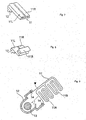
- a left portion 11L of the airbag 11 is folded toward the right side in such a manner that the left portion 11L is superposed on the top of the container 12 and, as shown in Fig. 6 , is further folded several times into a narrow width.
- the folds formed by this folding of the left portion 11L extend in the front-to-back direction.
- a right portion 11R of the airbag 11 is folded such that the right portion 11R is superposed on the top of the container 12 and is further folded several times into a narrow width as shown in Fig. 7 .
- the folds formed by this folding of the right portion 11R extend in the front-to-back direction.
- a front portion 11B of the airbag 11 is folded such that the front portion is superposed on the top of the container 12 and is further folded zigzag into a block shape.
- the folds formed by this folding of the front portion 11B extend in the left-to-right direction.
- the front portion 11B in the block shape is turned by 180° over the top of the container 12, whereby the folded portions of the airbag are entirely piled on the top of the container 12 ( Fig. 9 ). Then, this piled portion is slid (parallel movement) into the container 12 (see the arrow Z in Fig. 9 ).
- the lid is put on the container 12, thereby assembling the airbag apparatus.
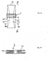
- the front portion 11B folded zigzag is disposed above (on the outlet side of the container 12) the rear portion 11A which is also folded zigzag.
- a gas passage W for introducing gas from the inflator 13 into the front portion 11B and the rear portion 11A exists at the vehicle front side (windshield side) in the piled body of the airbag.
- the direction of the gas passage W is completely opposite to the direction of arrow Z to extend along the front side (windshield side) of the piled body in a state that the folded bodies 11A, 11B are pushed out from the container 12 but still piled on each other.
- the airbag apparatus is installed in an upper portion of the instrument panel 20 which behind a windshield 21 extends substantially horizontally or slightly downward toward the rear side of the vehicle.
- the lid is torn to open and the airbag 11 starts to inflate as shown in Figs. 10(a), 10(b), 10(c) in this order.
- the front portion 11B and the rear portion 11A are pushed out from the container 12 in the still piled state as shown in Fig. 9 by gas pressure from the inflator 13.
- the gas flows through the gas passage W in the direction opposite to the direction of arrow Z of Fig.
- the airbag apparatus has a behavioral characteristic of first receiving the head of the occupant P.
- the aforementioned embodiment should be taken as an example of the present invention.
- the present invention can be adopted to another form not illustrated.
- the left portion 11L is folded before the right portion 11R is folded as shown in Figs. 5-7 in the aforementioned embodiment
- the right portion 11R may be folded before the left portion 11L is folded, or the left portion 11L and the right portion 11R may be folded simultaneously if possible.
- the left portion 11L and the right portion 11R may be folded zigzag.
- the present invention provides an airbag apparatus having such a behavioral characteristic that a front portion of an airbag is inflated earlier than a rear portion of the airbag.
Landscapes
- Engineering & Computer Science (AREA)
- Mechanical Engineering (AREA)
- Air Bags (AREA)
Description
- The present invention relates to an airbag apparatus which is suitably used as a passenger- or driver-side airbag apparatus installed in front of an occupant in a vehicle such as an automobile.
- A passenger-side airbag apparatus comprises a container arranged in an instrument panel in front of a front passenger seat, a gas generator for inflating an airbag, the airbag which is folded and accommodated in the container, and a lid covering the container. As a vehicle comes in collision, the gas generator is actuated to supply gas into the airbag, whereby the airbag starts to inflate. As the airbag starts to inflate, the lid is pushed by the airbag to open so that the airbag inflates toward the vehicle cabin.
- The airbag is provided with a gas inlet for receiving gas from the gas generator. The peripheral edge of the gas inlet is connected to the container.
- As described in
Japanese Patent Unexamined Publication H04-100754 - Hereinafter, the way of folding an airbag disclosed in the publication H04-100754 will be described with reference to
Figs. 11 through 17 . -
Fig. 11 is a perspective view showing anairbag 1 spread in a plane and asub container 2. Theairbag 1 is an envelop-like object of which theshorter sides 1b are rectilinear and the right and leftlonger sides 1a are curved in arc-like shape. Formed in the center of a layer on a side opposite to the surface to be arranged to confront an occupant is gas inlet 3 for receiving gas from an inflator. Also formed in the layer are gas outlets (vent holes) 4 for buffering impact on the occupant when the occupant collides with the deployed (fully inflated) airbag. Numeral 5 designates rivet holes. Thesub container 2 has a bottom face with holes 6 for passage of gas from the inflator. - As shown in
Fig. 12 , theairbag 1 is spread in a plane in a state that thesub container 2 is connected to theairbag 1. Then, as shown inFig. 13 and Fig. 14 (sectional view taken along a line XIV-XIV ofFig. 13 ), portions along thelonger sides 1a are folded inside theairbag 1 to make the width of theairbag 1 slightly smaller than the width of thesub container 2, so as to form an interim folded body. - Next, as shown in
Fig. 15 (side view taken from a line XV-XV ofFig. 13 ), the interim folded body is repeatedly folded into a bellow to make valley and mountain folds 7 in directions perpendicular to the rectilinearlonger sides 1a' of the interim folded body. As shown inFig. 16 , repeatedly folded portions are piled on each other to form a lump body and the lump body is accommodated in the sub container 2 (Fig. 17 ). - In this publication H04-100754, the folded airbag is accommodated in the
sub container 2 and thesub container 2 with the airbag is accommodated in a main container (not shown). However, the sub container may be omitted and in this case, the folded airbag is directly accommodated in a container. - In the conventional passenger-side airbag device, the
airbag 1 is folded so as to form the lump body. The peripheral edge of thegas inlet 3 of theairbag 1 is connected to thesub container 2. Assuming the area of theairbag 1 about the periphery of thegas inlet 3 is composed of two area: a windshield-side area 1A connected to awindshield side 2A of thesub container 2 and an occupant-side area 1B connected to the occupant-side 2B of thesub container 2, the windshield-side area 1A and the occupant-side area 1B are equal in length. - Therefore, when the
airbag 1 is inflated (deployed) by gas from the inflator, theairbag 1 is deployed such that a vehicle-front side portion i.e. the windshield side portion and a vehicle-rear side portion i.e. the occupant side portion of the airbag are substantially symmetrically inflated. - In
US 5,538,281 , a folded airbag is disclosed. The airbag is folded in such a manner that the front portion or upper end portion of the airbag is inflated earlier than a rear portion or bottom portion of the airbag. - It was found from various studies that the smooth deployment of the airbag may be obtained by such a structure that the front portion (vehicle-front side portion) of the airbag is inflated earlier than the rear portion (vehicle-rear side portion) of the airbag, but of course, it depends on the layout of the cabin and the arrangement angle of the instrument panel of the vehicle and the arrangement of the airbag apparatus.
- It is an object of the present invention to provide an airbag apparatus in which a front portion (vehicle-front side portion) of an airbag is inflated earlier than a rear portion (vehicle-rear side portion) of the airbag.
- According to the present invention, this object is achieved by an airbag device as defined in
claim 1 and a method for folding an airbag as defined inclaim 3. The dependent claims define an advantageous and preferred embodiment of the present invention. - An airbag apparatus of the present invention comprises a folded airbag and a gas generator for inflating the airbag, wherein the airbag is designed to be deployed in front of an occupant, where the airbag is folded such that a front portion thereof in the longitudinal direction of a vehicle is inflated earlier than a rear portion thereof. According to the present invention, the rear portion of the airbag is first folded, then left and right portions are then folded, and after that, the front portion is folded, thereby ensuring that the front portion is inflated earlier than the rear portion in a process of deployment of the airbag.
-
-
Figs. 1(a), 1(b) are illustrations for explaining a process of folding an airbag of an airbag apparatus according to an embodiment. -
Figs. 2(a), 2(b) are illustrations for explaining the process of folding the airbag of the airbag apparatus according to the embodiment. -
Figs. 3(a), 3(b) are illustrations for explaining the process of folding the airbag of the airbag apparatus according to the embodiment. -
Figs. 4(a), 4(b) are illustrations for explaining the process of folding the airbag of the airbag apparatus according to the embodiment. -
Fig. 5 is an illustration for explaining the process of folding the airbag of the airbag apparatus according to the embodiment. -
Fig. 6 is an illustration for explaining the process of folding the airbag of the airbag apparatus according to the embodiment. -
Fig. 7 is an illustration for explaining the process of folding the airbag of the airbag apparatus according to the embodiment. -
Fig. 8 is an illustration for explaining the process of folding the airbag of the airbag apparatus according to the embodiment. -
Fig. 9 is an illustration for explaining the process of folding the airbag of the airbag apparatus according to the embodiment. -
Figs. 10(a)-10(c) are illustration for explaining the inflating actions of the airbag apparatus according to the embodiment. -
Fig. 11 is a perspective view of a conventional example. -
Fig. 12 is a plane view of the conventional example. -
Fig. 13 is an illustration for explaining the process of folding an airbag of the conventional example. -
Fig. 14 is a sectional view taken along a line XIV-XIV ofFig. 13 . -
Fig. 15 is an illustration for explaining the process of folding the airbag of the conventional example. -
Fig. 16 is an illustration for explaining the process of folding the airbag of the conventional example. -
Fig. 17 is an illustration for explaining the process of folding the airbag of the conventional example. - Hereinafter, an embodiment of the present invention will be described with reference to the attached drawings.
Fig. 1(a) through Fig. 9 are illustrations for explaining a process of folding an airbag of a passenger-side airbag apparatus according to the embodiment.Figs. 1(a), 2(a), 3(a) ,4(a) andFigs. 5-8 are perspective views,Figs. 1(b), 2(b), 3(b) ,4(b) are sectional views taken along line B-B ofFigs. 1(a), 2(a), 3(a) ,4(a) , respectively, andFig. 9 is a sectional view showing a state that the folded airbag is about to be assembled into a container.Figs. 10(a)-10(c) are illustration for explaining profiles of the inflating airbag. - The passenger-
side airbag apparatus 10 comprises anairbag 11, acontainer 12 accommodating theairbag 11, aninflator 13 which is attached to thecontainer 12 for generating gas for inflating theairbag 11, and a lid (not shown) for covering an opening in the top of thecontainer 12. As shown inFig. 9 , theairbag 11 is secured around its gas inlet to thecontainer 12 by afastening member 14. - For folding and accommodating the
airbag 11 into thecontainer 12, theairbag 11 is first spread in plain as shown inFigs. 1(a), 1(b) and is folded in such a manner that arear portion 11A, to be arranged at the vehicle-rear side (at theinstrument panel 20 side inFig. 10 ), is superposed on the top of thecontainer 12. After that, as shown inFigs. 3(a), 3(b) , therear portion 11A is folded zigzag into a block shape which is long and narrow in the left-to-right direction. The folds formed by this folding extend in the left-to-right direction of theairbag 11. - The
rear portion 11A in the block shape is reversed according to an arrow inFig. 3(b) and is sunk inside theairbag 11 as shown inFigs. 4(a), 4(b) . - After that, as shown in
Fig. 5 , aleft portion 11L of theairbag 11 is folded toward the right side in such a manner that theleft portion 11L is superposed on the top of thecontainer 12 and, as shown inFig. 6 , is further folded several times into a narrow width. The folds formed by this folding of theleft portion 11L extend in the front-to-back direction. - Then, in a symmetrical manner as the
left portion 11L, aright portion 11R of theairbag 11 is folded such that theright portion 11R is superposed on the top of thecontainer 12 and is further folded several times into a narrow width as shown inFig. 7 . The folds formed by this folding of theright portion 11R extend in the front-to-back direction. - After that, as shown in
Fig. 8 , afront portion 11B of theairbag 11 is folded such that the front portion is superposed on the top of thecontainer 12 and is further folded zigzag into a block shape. The folds formed by this folding of thefront portion 11B extend in the left-to-right direction. Thefront portion 11B in the block shape is turned by 180° over the top of thecontainer 12, whereby the folded portions of the airbag are entirely piled on the top of the container 12 (Fig. 9 ). Then, this piled portion is slid (parallel movement) into the container 12 (see the arrow Z inFig. 9 ). The lid is put on thecontainer 12, thereby assembling the airbag apparatus. As shown inFig. 9 , thefront portion 11B folded zigzag is disposed above (on the outlet side of the container 12) therear portion 11A which is also folded zigzag. Further, as shown inFig. 9 , a gas passage W for introducing gas from the inflator 13 into thefront portion 11B and therear portion 11A exists at the vehicle front side (windshield side) in the piled body of the airbag. The direction of the gas passage W is completely opposite to the direction of arrow Z to extend along the front side (windshield side) of the piled body in a state that the foldedbodies container 12 but still piled on each other. - As shown in
Fig. 10(a) , the airbag apparatus is installed in an upper portion of theinstrument panel 20 which behind awindshield 21 extends substantially horizontally or slightly downward toward the rear side of the vehicle. As the inflator 13 is actuated to spout out gas in the event of a vehicle collision, the lid is torn to open and theairbag 11 starts to inflate as shown inFigs. 10(a), 10(b), 10(c) in this order. In this case, thefront portion 11B and therear portion 11A are pushed out from thecontainer 12 in the still piled state as shown inFig. 9 by gas pressure from theinflator 13. The gas flows through the gas passage W in the direction opposite to the direction of arrow Z ofFig. 9 so as to flow preferentially into thefront portion 11B to inflate thefront portion 11B, whereby theairbag 11 first receives the head of an occupant P as shown inFig. 10(b) . Then, as shown inFig. 10(c) , therear portion 11A of theairbag 11 is also inflated so as to receive the upper body of the occupant P. In this manner, the airbag apparatus has a behavioral characteristic of first receiving the head of the occupant P. - The aforementioned embodiment should be taken as an example of the present invention. The present invention can be adopted to another form not illustrated. For example, though the
left portion 11L is folded before theright portion 11R is folded as shown inFigs. 5-7 in the aforementioned embodiment, theright portion 11R may be folded before theleft portion 11L is folded, or theleft portion 11L and theright portion 11R may be folded simultaneously if possible. Theleft portion 11L and theright portion 11R may be folded zigzag. - As described above, the present invention provides an airbag apparatus having such a behavioral characteristic that a front portion of an airbag is inflated earlier than a rear portion of the airbag.
Claims (4)
- An airbag apparatus (10) to be installed in a vehicle, comprising a folded airbag (11) and a gas generator (13) for inflating the airbag (11), the airbag (11) being designed to be deployed in front of an occupant (P),
wherein the airbag (11) comprises, in the longitudinal direction of the vehicle, a front portion (11B) and a rear portion (11A), and
wherein the airbag (11) is folded such that the front portion (11B) is inflated earlier than the rear portion (11A),
characterized in that
the rear portion (11A) of the airbag (11) is first folded, then left and right portions (11L, 11R) of the airbag (11) are folded, and
after that the front portion (11B) is folded and disposed above the folded rear portion (11A). - The airbag apparatus (10) according to claim 1,
wherein the front portion (11B) is folded zigzag into a block shape. - A method for folding an airbag (11) to be installed in a vehicle, the airbag (11) being designed to be deployed in front of an occupant (P) in the vehicle,
wherein, in the longitudinal direction of the vehicle, the airbag (11) comprises a front portion (11B) and a rear portion (11A), and
wherein the airbag (11) is folded such that the front portion (11B) is inflated earlier than the rear portion (11A),
characterized in that
the rear portion (11A) of the airbag (11) is first folded, then left and right portions (11L, 11R) of the airbag (11) are folded, and after that the front portion (11B) is folded and disposed above the folded rear portion (11A). - The method according to claim 3,
wherein the front portion (11B) is folded zigzag into a block shape.
Applications Claiming Priority (2)
| Application Number | Priority Date | Filing Date | Title |
|---|---|---|---|
| JP2001110200A JP4882157B2 (en) | 2001-04-09 | 2001-04-09 | Airbag device |
| JP2001110200 | 2001-04-09 |
Publications (3)
| Publication Number | Publication Date |
|---|---|
| EP1249374A2 EP1249374A2 (en) | 2002-10-16 |
| EP1249374A3 EP1249374A3 (en) | 2005-07-13 |
| EP1249374B1 true EP1249374B1 (en) | 2009-11-18 |
Family
ID=18962017
Family Applications (1)
| Application Number | Title | Priority Date | Filing Date |
|---|---|---|---|
| EP02006526A Expired - Lifetime EP1249374B1 (en) | 2001-04-09 | 2002-03-19 | Airbag apparatus |
Country Status (4)
| Country | Link |
|---|---|
| US (1) | US6988743B2 (en) |
| EP (1) | EP1249374B1 (en) |
| JP (1) | JP4882157B2 (en) |
| DE (1) | DE60234403D1 (en) |
Families Citing this family (18)
| Publication number | Priority date | Publication date | Assignee | Title |
|---|---|---|---|---|
| US20040251669A1 (en) * | 2001-03-30 | 2004-12-16 | Trw Vehicle Safety Systems Inc. | Method of folding air bag and an associated apparatus |
| JP2003327183A (en) * | 2002-05-15 | 2003-11-19 | Takata Corp | Air bag device for motorcycle, manufacturing method of air bag device for motorcycle and motorcycle with air bag device |
| DE10257168A1 (en) | 2002-12-03 | 2004-07-01 | Takata Corp. | Airbag for an occupant protection device |
| US7223224B2 (en) * | 2003-01-27 | 2007-05-29 | Tk Holdings Inc. | Airbag folding method |
| JP2005238973A (en) * | 2004-02-26 | 2005-09-08 | Nippon Plast Co Ltd | Airbag, airbag folding method and airbag device |
| DE102005015519A1 (en) * | 2005-04-04 | 2006-10-05 | Acts Advanced Car Technology Systems Gmbh & Co.Kg | Airbag for passenger protection in motor vehicle, has right or left side part foldable about fold line diagonal to airbag longitudinal axis and front part foldable over another, perpendicular fold line |
| US7441804B2 (en) * | 2005-04-27 | 2008-10-28 | Autoliv Asp, Inc. | Airbag cushion folding method |
| US7845682B2 (en) * | 2005-04-27 | 2010-12-07 | Autoliv Asp, Inc. | Airbag cushion folding methods |
| US7942442B2 (en) * | 2005-04-27 | 2011-05-17 | Autoliv Asp, Inc. | Airbag cushion folding methods |
| JP4909556B2 (en) * | 2005-10-04 | 2012-04-04 | 日本プラスト株式会社 | Airbag |
| DE102007005304B4 (en) * | 2007-02-02 | 2010-11-11 | Autoliv Development Ab | airbag |
| US7735862B2 (en) * | 2007-05-16 | 2010-06-15 | Autoliv Asp, Inc | Airbag cushion folding method for out-of-position conditions |
| JP5271916B2 (en) * | 2007-11-22 | 2013-08-21 | オートリブ ディベロップメント エービー | Airbag device for passenger seat |
| US7926844B2 (en) * | 2008-04-10 | 2011-04-19 | Autoliv Asp, Inc. | Airbag assembly and method of packing |
| US8226118B2 (en) * | 2009-08-05 | 2012-07-24 | Autoliv Asp, Inc. | Safety venting with passively closeable vents |
| US8407968B2 (en) * | 2009-10-16 | 2013-04-02 | Autoliv Asp, Inc. | Method of packaging an inflatable airbag cushion including a wrapper and deployment flap |
| US8540276B2 (en) | 2011-11-07 | 2013-09-24 | Autoliv Asp, Inc. | Inflatable knee airbag assemblies with cushion fold pattern |
| CN105128809B (en) * | 2015-08-31 | 2018-07-17 | 延锋百利得(上海)汽车安全系统有限公司 | A kind of method for folding of air bag and safety airbag |
Family Cites Families (18)
| Publication number | Priority date | Publication date | Assignee | Title |
|---|---|---|---|---|
| JPH0446842A (en) * | 1990-06-13 | 1992-02-17 | Nippon Plast Co Ltd | Gas bag |
| JP3003182B2 (en) * | 1990-08-20 | 2000-01-24 | タカタ株式会社 | How to fold the passenger airbag |
| US5178407A (en) * | 1991-07-08 | 1993-01-12 | Trw Vehicle Safety System Inc. | Folded air bag |
| JP3366051B2 (en) * | 1993-05-18 | 2003-01-14 | 本田技研工業株式会社 | Airbag device |
| US5492367A (en) * | 1994-02-07 | 1996-02-20 | General Motors Corporation | Method and system for folding an air bag |
| US5538281A (en) * | 1995-03-31 | 1996-07-23 | Trw Vehicle Safety Systems Inc. | Folded air bag |
| US5531477A (en) * | 1995-06-06 | 1996-07-02 | Alliedsignal Inc. | Method of folding an airbag |
| DE19733143A1 (en) * | 1996-08-02 | 1998-02-05 | Denso Corp | Air bag unit for vehicles |
| US5873598A (en) * | 1996-08-27 | 1999-02-23 | Toyo Tire & Rubber Co., Ltd. | Air bag device |
| JP2973294B2 (en) * | 1997-01-10 | 1999-11-08 | 東洋ゴム工業株式会社 | Airbag device |
| JP3142055B2 (en) * | 1996-08-30 | 2001-03-07 | 株式会社デンソー | Airbag device and folding method thereof |
| JP3367378B2 (en) * | 1997-04-25 | 2003-01-14 | 豊田合成株式会社 | Airbag module |
| JPH11165607A (en) * | 1997-12-02 | 1999-06-22 | Mitsubishi Motors Corp | Airbag device |
| JPH11321511A (en) * | 1998-05-11 | 1999-11-24 | Takata Kk | Air bag for front passenger seat and folding method therefor |
| US6121865A (en) | 1998-08-03 | 2000-09-19 | Caterpillar Inc. | Solenoid assembly having a sealing device for the electrical leads |
| DE19926425B4 (en) * | 1999-06-10 | 2008-07-10 | Adam Opel Ag | Inflator for an airbag unit |
| GB2369328A (en) * | 2000-11-28 | 2002-05-29 | Autoliv Dev | An air-bag arrangement for mounting in the dashboard of a motor vehicle |
| JP4465873B2 (en) * | 2000-12-19 | 2010-05-26 | 豊田合成株式会社 | Airbag device for passenger seat |
-
2001
- 2001-04-09 JP JP2001110200A patent/JP4882157B2/en not_active Expired - Fee Related
-
2002
- 2002-03-19 EP EP02006526A patent/EP1249374B1/en not_active Expired - Lifetime
- 2002-03-19 DE DE60234403T patent/DE60234403D1/en not_active Expired - Lifetime
- 2002-04-05 US US10/116,083 patent/US6988743B2/en not_active Expired - Lifetime
Also Published As
| Publication number | Publication date |
|---|---|
| DE60234403D1 (en) | 2009-12-31 |
| US20020145272A1 (en) | 2002-10-10 |
| JP2002308032A (en) | 2002-10-23 |
| EP1249374A2 (en) | 2002-10-16 |
| JP4882157B2 (en) | 2012-02-22 |
| US6988743B2 (en) | 2006-01-24 |
| EP1249374A3 (en) | 2005-07-13 |
Similar Documents
| Publication | Publication Date | Title |
|---|---|---|
| EP1249374B1 (en) | Airbag apparatus | |
| US6073960A (en) | Air bag assembly | |
| EP1607277B1 (en) | Airbag apparatus for head-protecting | |
| EP1660355B1 (en) | Gas flow deflection apparatus and method for airbag systems | |
| US5746447A (en) | Airbag module | |
| JP3017153U (en) | Sectioned airbag knee support unit | |
| EP1832475B1 (en) | Side air bag device for vehicle | |
| JP4285167B2 (en) | Side airbag device | |
| US7992892B2 (en) | Inflatable ramp for inflatable curtain side impact restraint | |
| US5590903A (en) | Deployment door assembly | |
| US6382660B1 (en) | Air bag assembly | |
| EP3720740B1 (en) | Side airbag with accordion pelvis fold | |
| US20120074677A1 (en) | Airbag, airbag device, and method for sewing lid member of airbag | |
| EP4090559B1 (en) | Vehicle having a seat and an airbag assembly | |
| EP0839692B1 (en) | Airbag apparatus | |
| EP1176061B1 (en) | Airbag apparatus | |
| JP4907175B2 (en) | Seat seat device | |
| US6848715B2 (en) | Folded rigid knee airbag | |
| EP1939049B1 (en) | Pedestrian airbag and pedestrian airbag device | |
| EP1944201B1 (en) | Occupant leg part restraining apparatus and retainer | |
| EP1318054B1 (en) | Externally-developed air bag device | |
| KR100260874B1 (en) | Air bag module cover | |
| JP2007230396A (en) | Airbag and airbag device | |
| US20080036189A1 (en) | Airbag | |
| EP1953046B1 (en) | Vehicle occupant restraint system |
Legal Events
| Date | Code | Title | Description |
|---|---|---|---|
| PUAI | Public reference made under article 153(3) epc to a published international application that has entered the european phase |
Free format text: ORIGINAL CODE: 0009012 |
|
| AK | Designated contracting states |
Kind code of ref document: A2 Designated state(s): AT BE CH CY DE DK ES FI FR GB GR IE IT LI LU MC NL PT SE TR |
|
| AX | Request for extension of the european patent |
Free format text: AL;LT;LV;MK;RO;SI |
|
| PUAL | Search report despatched |
Free format text: ORIGINAL CODE: 0009013 |
|
| AK | Designated contracting states |
Kind code of ref document: A3 Designated state(s): AT BE CH CY DE DK ES FI FR GB GR IE IT LI LU MC NL PT SE TR |
|
| AX | Request for extension of the european patent |
Extension state: AL LT LV MK RO SI |
|
| RIC1 | Information provided on ipc code assigned before grant |
Ipc: 7B 60R 21/00 B Ipc: 7B 60R 21/22 A |
|
| 17P | Request for examination filed |
Effective date: 20051206 |
|
| AKX | Designation fees paid |
Designated state(s): DE FR GB SE |
|
| 17Q | First examination report despatched |
Effective date: 20061228 |
|
| GRAP | Despatch of communication of intention to grant a patent |
Free format text: ORIGINAL CODE: EPIDOSNIGR1 |
|
| RIC1 | Information provided on ipc code assigned before grant |
Ipc: B60R 21/237 20060101AFI20090707BHEP |
|
| GRAS | Grant fee paid |
Free format text: ORIGINAL CODE: EPIDOSNIGR3 |
|
| GRAA | (expected) grant |
Free format text: ORIGINAL CODE: 0009210 |
|
| RIN1 | Information on inventor provided before grant (corrected) |
Inventor name: OKAMOTO, HIDEAKI,C/O TAKATA CORPORATION Inventor name: KUMAGAI, MASAYOSHI,C/O TAKATA CORPORATION |
|
| AK | Designated contracting states |
Kind code of ref document: B1 Designated state(s): DE FR GB SE |
|
| REG | Reference to a national code |
Ref country code: GB Ref legal event code: FG4D |
|
| REF | Corresponds to: |
Ref document number: 60234403 Country of ref document: DE Date of ref document: 20091231 Kind code of ref document: P |
|
| PG25 | Lapsed in a contracting state [announced via postgrant information from national office to epo] |
Ref country code: SE Free format text: LAPSE BECAUSE OF FAILURE TO SUBMIT A TRANSLATION OF THE DESCRIPTION OR TO PAY THE FEE WITHIN THE PRESCRIBED TIME-LIMIT Effective date: 20091118 |
|
| PLBE | No opposition filed within time limit |
Free format text: ORIGINAL CODE: 0009261 |
|
| STAA | Information on the status of an ep patent application or granted ep patent |
Free format text: STATUS: NO OPPOSITION FILED WITHIN TIME LIMIT |
|
| 26N | No opposition filed |
Effective date: 20100819 |
|
| REG | Reference to a national code |
Ref country code: FR Ref legal event code: ST Effective date: 20101130 |
|
| PG25 | Lapsed in a contracting state [announced via postgrant information from national office to epo] |
Ref country code: FR Free format text: LAPSE BECAUSE OF NON-PAYMENT OF DUE FEES Effective date: 20100331 |
|
| PGFP | Annual fee paid to national office [announced via postgrant information from national office to epo] |
Ref country code: GB Payment date: 20130313 Year of fee payment: 12 |
|
| PGFP | Annual fee paid to national office [announced via postgrant information from national office to epo] |
Ref country code: DE Payment date: 20140417 Year of fee payment: 13 |
|
| GBPC | Gb: european patent ceased through non-payment of renewal fee |
Effective date: 20140319 |
|
| PG25 | Lapsed in a contracting state [announced via postgrant information from national office to epo] |
Ref country code: GB Free format text: LAPSE BECAUSE OF NON-PAYMENT OF DUE FEES Effective date: 20140319 |
|
| REG | Reference to a national code |
Ref country code: DE Ref legal event code: R119 Ref document number: 60234403 Country of ref document: DE |
|
| PG25 | Lapsed in a contracting state [announced via postgrant information from national office to epo] |
Ref country code: DE Free format text: LAPSE BECAUSE OF NON-PAYMENT OF DUE FEES Effective date: 20151001 |