EP1249250A1 - Flexible needle assembly - Google Patents
Flexible needle assembly Download PDFInfo
- Publication number
- EP1249250A1 EP1249250A1 EP20020007628 EP02007628A EP1249250A1 EP 1249250 A1 EP1249250 A1 EP 1249250A1 EP 20020007628 EP20020007628 EP 20020007628 EP 02007628 A EP02007628 A EP 02007628A EP 1249250 A1 EP1249250 A1 EP 1249250A1
- Authority
- EP
- European Patent Office
- Prior art keywords
- hub
- needle
- needle cannula
- medication delivery
- medication
- Prior art date
- Legal status (The legal status is an assumption and is not a legal conclusion. Google has not performed a legal analysis and makes no representation as to the accuracy of the status listed.)
- Granted
Links
Images



Classifications
-
- A—HUMAN NECESSITIES
- A61—MEDICAL OR VETERINARY SCIENCE; HYGIENE
- A61M—DEVICES FOR INTRODUCING MEDIA INTO, OR ONTO, THE BODY; DEVICES FOR TRANSDUCING BODY MEDIA OR FOR TAKING MEDIA FROM THE BODY; DEVICES FOR PRODUCING OR ENDING SLEEP OR STUPOR
- A61M5/00—Devices for bringing media into the body in a subcutaneous, intra-vascular or intramuscular way; Accessories therefor, e.g. filling or cleaning devices, arm rests
- A61M5/178—Syringes
- A61M5/31—Details
- A61M5/32—Needles; Details of needles pertaining to their connection with syringe or hub; Accessories for bringing the needle into, or holding the needle on, the body; Devices for protection of needles
- A61M5/34—Constructions for connecting the needle, e.g. to syringe nozzle or needle hub
-
- A—HUMAN NECESSITIES
- A61—MEDICAL OR VETERINARY SCIENCE; HYGIENE
- A61M—DEVICES FOR INTRODUCING MEDIA INTO, OR ONTO, THE BODY; DEVICES FOR TRANSDUCING BODY MEDIA OR FOR TAKING MEDIA FROM THE BODY; DEVICES FOR PRODUCING OR ENDING SLEEP OR STUPOR
- A61M5/00—Devices for bringing media into the body in a subcutaneous, intra-vascular or intramuscular way; Accessories therefor, e.g. filling or cleaning devices, arm rests
- A61M5/178—Syringes
- A61M5/31—Details
- A61M5/32—Needles; Details of needles pertaining to their connection with syringe or hub; Accessories for bringing the needle into, or holding the needle on, the body; Devices for protection of needles
- A61M5/34—Constructions for connecting the needle, e.g. to syringe nozzle or needle hub
- A61M2005/341—Constructions for connecting the needle, e.g. to syringe nozzle or needle hub angularly adjustable or angled away from the axis of the injector
Definitions
- This invention relates generally to the field of medication delivery systems and, more particularly, to flexible needle assemblies for use with medication delivery pens.
- Medication delivery pens such as hypodermic syringes, are used for self-injection of precisely measured doses of medication and are widely used, for example, by diabetics to dispense insulin. Medication delivery pens may also be used to inject human growth hormone as well as other types of liquid medication into a patient.
- a typical prior art medication delivery system includes a pen having a cartridge, a plunger and a needle assembly.
- the pen is typically fabricated from a plastic or polymer material and has generally a tubular structure that is approximately the dimensions of a conventional writing pen.
- the cartridge which contains a volume of liquid medication, is generally an elongated tube of glass or plastic that has a pierceable rubber septum extending across a distal end of the cartridge.
- the plunger is used to urge the medication, which is stored in the cartridge, out of the distal end of the cartridge.
- the needle assembly includes an elongated needle cannula having opposed proximal and distal portions.
- the cylindrical wall of a needle hub surrounds the proximal point on the needle cannula and includes an array of internal threads for engaging external threads on the neck of the pen cartridge retainer or an adaptor.
- Syringe systems as disclosed in U.S. Patent Nos. 5,599,323 (Bonnichsen et al.) and 5,462,535 (Bonnichsen et al.) relate to a syringe system having a pen shaped syringe with a cartridge containing insulin and an injection needle.
- U.S. Patent No. 5,951,530 (Steengaard et. al.) relates to an injection needle mounted in a needle hub fitting onto an injection device from which preset doses of medicine from a cartridge accommodated in the device is administered.
- U.S. Patent No. 3,884,230 (Wulff) relates to a flexible needle and guard device for a hypodermic syringe.
- the device includes a flexure tube interconnected between the syringe and the needle.
- the Wulff device has a flexible needle, rather than a flexible hub.
- one embodiment of the present invention is directed to a needle assembly for use with a medication delivery pen.
- the needle assembly has a needle cannula with a proximal portion and a distal portion.
- a hub, to which the needle cannula is mounted, includes a flexible roof portion. The flexible roof portion permits the needle cannula to move about the centerline of the hub.
- Another embodiment of the present invention is directed to a medication delivery system that includes a medication delivery pen and a cartridge containing medication.
- the cartridge is disposed within the medication delivery pen.
- a needle assembly is engageable with the cartridge and includes a needle cannula and a hub.
- the needle cannula has a proximal portion and a distal portion.
- the needle cannula is mounted to the hub, which includes a flexible roof portion, which permits the needle cannula to move about the centerline of the hub.
- the medication can flow through the needle cannula during an injection procedure.
- Yet another embodiment of the present invention is directed to a method of operating a medication delivery system.
- the method includes attaching a needle cannula, which has a proximal portion and a distal portion, to a hub.
- the hub includes a flexible roof portion.
- the proximal portion of the needle cannula is coupled to a cartridge containing medication.
- the cartridge within the medication delivery pen dispenses medication.
- the next step is to inject the distal portion of the needle cannula into a patient and deliver the medication into the patient.
- the flexible roof portion of the hub permits the needle cannula to move about the centerline of the hub.
- Yet another embodiment is directed to a needle assembly in which the hub and cannula are disposed in a ball-and-socket relationship. This ball-and-socket relationship permits the cannula to rotate relative to the hub.
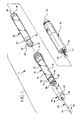
- Fig. 1 is an exploded perspective view a medication pen in accordance with the present invention.
- Fig. 2 is a partially cut-away view of a needle assembly in accordance with the present invention.
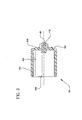
- Fig. 3 is a cross-sectional view of a needle assembly in accordance with the present invention.
- Fig. 4 shows the operation of a needle assembly in accordance with the present invention.
- Fig. 5 shows a side view of the needle hub in accordance with the present invention.
- Fig. 6 shows a side view of the needle hub in accordance with a ball-and-socket embodiment of the present invention.
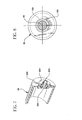
- Fig. 7 shows a partial cut-away perspective view of the needle hub in accordance with the ball-and-socket embodiment of the present invention.
- Fig. 8 shows an end view of the needle assembly in accordance with the present invention.
- the present invention relates to a needle assembly that compensates for unintended or inadvertent movement of a medication pen.
- the apparatus and method permit a needle cannula to move about the centerline of a hub of the needle assembly.
- Fig. 1 shows a medication delivery pen 11 according to the present invention.
- a needle assembly is identified generally by the numeral 46.
- medication delivery pen 11 includes a cartridge retainer assembly 10, a dosing apparatus 38 and a cartridge assembly 22.
- Needle assembly 46 as described in more detail below, is designed to be attached to a needle mounting insert tip 20 on cartridge retainer assembly 10.
- Cartridge retainer assembly 10 as shown in Fig. 1 includes an elongate generally tubular body 12.
- a generally tubular needle mounting insert tip 20 is snap-fit mounted in distal end 16 of body 12 and cartridge retainer assembly 10 is dimensioned and configured to receive cartridge assembly 22 therein.
- Cartridge assembly 22 includes an open proximal end 26 and a distal end 25, which is defined by an inwardly converging shoulder 28.
- a pierceable and resealable rubber septum 32 extends completely across the open distal end defined by neck 30. Rubber septum 32 is held in place by a metallic sleeve 34.
- Medication such as insulin, heparin or other liquid medication is pre-filled into cartridge assembly 22 and is retained therein by a rubber stopper 36. Stopper 36 is in sliding fluid-tight engagement with the tubular wall of cartridge assembly 22. Distally directed forces on stopper 36 urge the medication from pen 11.
- Dosing apparatus 38 is generally cylindrical and includes opposed proximal and distal ends 40 and 42, respectively. Threads 41 are disposed at distal end 42 of dosing apparatus 38 for releasable threaded engagement with proximal end 14 of body 12 of cartridge retainer assembly 10.
- a plunger rod 44 projects distally from dosing apparatus 38 and is dimensioned to engage stopper 36 of cartridge assembly 22.
- Dosing apparatus 38 also includes known mechanisms for setting a selected dose of medication to be delivered by pen 11.
- a dispensing mechanism (not shown) is operative to drive plunger rod 44 a selected distance in a distal direction for moving stopper 36 a distance that will inject the selected dose of medication from cartridge assembly 22.
- Needle assembly 46 includes a needle cannula 48 with opposed proximal and distal tips 50 and 52, respectively, and a lumen 51 extending entirely therethrough. Needle cannulas having a gauge of approximately between 27 and 31 are typically used. The usable length of the needle cannula is typically between 0.157" (4 mm) and 0.394" (10 mm). Cannula 48 is either insert molded or retained with adhesive within cap or hub 56. Cap or hub 56 (referred to hub 56 herein) of needle assembly 46 includes an array of internal threads (not shown) for removably mounting needle assembly 46 to needle mounting insert tip 20 on cartridge retainer assembly 10 using external threads 88.
- needle assembly 46 can be provided with other releasable engagement means between needle assembly 46 and cartridge retainer assembly 10 .
- external threads can be formed on needle assembly 46 and corresponding internal threads can be defined on cartridge retainer assembly 10 or a bayonet style mounting using lugs and slots can be used.
- needle assembly 46 could be "snap fit" on to cartridge retainer assembly 10.
- a support 54 such as cork, is used to secure needle cannula 48 to needle hub 56.
- body 12 of cartridge retainer assembly 10 includes a plurality of inwardly projecting supports 65 separated from one another by notches 62, wherein supports 65 are used to hold insert tip 20 in distal end 16 of cartridge retainer assembly 10.
- Medication delivery pen 11 is used by mounting needle assembly 46 to needle mounting insert tip 20 of cartridge retainer assembly 10. This mounting is achieved by moving needle assembly 46 in a proximal direction over needle mounting insert tip 20 until the threads (not shown) of cap, or hub, 56 engage external threads 88 on needle mounting insert tip 20. Threads 88 of needle mounting insert tip 20 are spaced from the extreme distal end of needle mounting insert tip 20, therefore, the initial axial advancement of cap 56 over needle mounting insert tip 20 will cause proximal point 50 of needle cannula 48 to pierce rubber septum 32 of cartridge assembly 22 prior to rotational threaded engagement of needle assembly 46 with needle mounting insert tip 20. Thus, a bevel (not shown) that defines proximal point 50 will advance axially through septum 32 without a rotation that could tear rubber septum 32.
- Fig. 2 is a partially cut-away perspective view of a needle assembly 46 in accordance with the present invention.
- Needle assembly 46 includes a needle cannula 48 and a needle hub 56.
- the needle cannula 48 has opposed proximal and distal points 50 and 52, respectively and proximal and distal portions 160 and 164, respectively.
- Hub portion 56 includes a cannula/hub interface 166 that is securely affixed at an intermediate position along shaft 176, which holds cannula 48.
- Hub 56 has a roof portion 180 with concentric raised ribs 168(a)...(n) (where n is any suitable number). Although only two ribs are shown, any number of ribs could be used.
- Ribs 168(a)...(n) permit the needle cannula 48 to move about the centerline of the hub 56. Threads or camming surface 188 attach to threads on the cartridge retainer assembly (shown in Fig. 1 as 88).
- the needle cannula 48 typically has an outer diameter of approximately 0.009 inches to 0.018 inches and an inner diameter of approximately 0.0055 inches to 0.0120 inches.
- the needle cannula 48 is typically fabricated from materials such as stainless steel.
- Fig. 3 shows a cross-sectional view along a longitudinal axis of the hub 56 that is attached to a cartridge retainer assembly (shown in Fig. 1 as element 10).
- Hub 56 is attached by camming surface 190 interfacing with a surface of wall 192, although other means of attachment could be used to connect hub 56 and cartridge retainer assembly.
- the needle cannula 48 is free to move with respect to the axial center line 208 of the hub 56.
- Flexibility is provided by concentric ribs, generally, 168 located on an area of the roof portion 180. Other flex means on the roof 180 of the hub 56 can be substituted in place of (or in combination with) the ribs 168.
- Shaft 176 extends through roof 180, and provides support for needle cannula 48.
- Fig. 4 shows a cross-sectional view of needle assembly 46.
- Flexible hub assembly 56 has concentric ribs 168 or other flexing means that permit the cannula 48 to move relative to the centerline 208 at an angle ⁇ .
- the angle ⁇ typically has a magnitude of approximately between 0-45 degrees.
- the flexing means can include a flexible roof portion 180 or ribs 168, which can be used in conjunction with the flexible roof portion or by themselves.
- Fig. 5 shows a side view of needle hub 56.
- roof portion 181 is raised and fabricated from an elastomeric material that provides flexibility in a similar fashion as the ribs described herein.
- the raised roof portion 181 is at a plane different than the proximal surface 180 of the hub 56. This flexibility permits a needle cannula to move relative to a centerline.
- Support 182, which supports the cannula, is also shown.
- the raised roof portion 181 provides flexibility for a needle cannula (not shown).
- the flexible raised roof portion 181 can be used instead of, or in conjunction with, the ribs described herein.
- Fig. 6 shows a side view of the needle hub in accordance with the ball-and-socket embodiment of the present invention.
- Hub 56 has surface 680 upon which section 681, which forms a socket, is mounted.
- Shaft 682 extends from section 681 and rotational ball portion 684, which is connected to shaft 682, is disposed so as to form a ball-and-socket configuration with section 681.
- This ball-and-socket configuration permits the shaft 682 to hold a needle cannula (not shown in Fig. 6) such that the cannula rotates about the centerline of hub 56.
- shaft portion 682 and rotational ball portion 684 could be fabricated as a single piece. They are labeled individually herein for explanation purposes.
- Fig. 7 shows a cut-away perspective view of the hub 56 in the ball-and-socket embodiment. Roof portion 680, socket portion 681, shaft 682 and rotational ball portion 684 are shown. Support 681 surrounds shaft 682 and provides a means to secure shaft 682 to roof portion 680.
- the ball-and-socket configuration enables rotation of the cannula about the centerline of the hub.
- Fig. 8 shows an end view of the hub 56. Ribs 168 are disposed on roof portion 180. An end-view of needle cannula 48 is also shown.
Landscapes
- Health & Medical Sciences (AREA)
- Vascular Medicine (AREA)
- Engineering & Computer Science (AREA)
- Anesthesiology (AREA)
- Biomedical Technology (AREA)
- Heart & Thoracic Surgery (AREA)
- Hematology (AREA)
- Life Sciences & Earth Sciences (AREA)
- Animal Behavior & Ethology (AREA)
- General Health & Medical Sciences (AREA)
- Public Health (AREA)
- Veterinary Medicine (AREA)
- Infusion, Injection, And Reservoir Apparatuses (AREA)
Abstract
Description
- This invention relates generally to the field of medication delivery systems and, more particularly, to flexible needle assemblies for use with medication delivery pens.
- Medication delivery pens, such as hypodermic syringes, are used for self-injection of precisely measured doses of medication and are widely used, for example, by diabetics to dispense insulin. Medication delivery pens may also be used to inject human growth hormone as well as other types of liquid medication into a patient.
- A typical prior art medication delivery system includes a pen having a cartridge, a plunger and a needle assembly. The pen is typically fabricated from a plastic or polymer material and has generally a tubular structure that is approximately the dimensions of a conventional writing pen.
- The cartridge, which contains a volume of liquid medication, is generally an elongated tube of glass or plastic that has a pierceable rubber septum extending across a distal end of the cartridge.
- The plunger is used to urge the medication, which is stored in the cartridge, out of the distal end of the cartridge.
- The needle assembly includes an elongated needle cannula having opposed proximal and distal portions. The cylindrical wall of a needle hub surrounds the proximal point on the needle cannula and includes an array of internal threads for engaging external threads on the neck of the pen cartridge retainer or an adaptor.
- Syringe systems as disclosed in U.S. Patent Nos. 5,599,323 (Bonnichsen et al.) and 5,462,535 (Bonnichsen et al.) relate to a syringe system having a pen shaped syringe with a cartridge containing insulin and an injection needle.
- U.S. Patent No. 5,951,530 (Steengaard et. al.) relates to an injection needle mounted in a needle hub fitting onto an injection device from which preset doses of medicine from a cartridge accommodated in the device is administered.
- U.S. Patent No. 3,884,230 (Wulff) relates to a flexible needle and guard device for a hypodermic syringe. The device includes a flexure tube interconnected between the syringe and the needle. However, the Wulff device has a flexible needle, rather than a flexible hub.
- One disadvantage to conventional medication delivery pens as disclosed in the prior art is that some patients may have a tendency to inadvertently move or otherwise jitter the needle assembly while injecting the medication. This can cause pain and/or skin trauma because the piercing procedure is not as precise as possible.
- Accordingly, there is a need in the art for an apparatus and method that reduce the pain and skin trauma associated with unintended motion of a needle assembly while injecting medication.
- There is also a need for an apparatus and method that permit the needle cannula to move about the centerline of the hub of a needle assembly.
- Accordingly, one embodiment of the present invention is directed to a needle assembly for use with a medication delivery pen. The needle assembly has a needle cannula with a proximal portion and a distal portion. A hub, to which the needle cannula is mounted, includes a flexible roof portion. The flexible roof portion permits the needle cannula to move about the centerline of the hub.
- Another embodiment of the present invention is directed to a medication delivery system that includes a medication delivery pen and a cartridge containing medication. The cartridge is disposed within the medication delivery pen. A needle assembly is engageable with the cartridge and includes a needle cannula and a hub. The needle cannula has a proximal portion and a distal portion. The needle cannula is mounted to the hub, which includes a flexible roof portion, which permits the needle cannula to move about the centerline of the hub. Thus, the medication can flow through the needle cannula during an injection procedure.
- Yet another embodiment of the present invention is directed to a method of operating a medication delivery system. The method includes attaching a needle cannula, which has a proximal portion and a distal portion, to a hub. The hub includes a flexible roof portion. Next, the proximal portion of the needle cannula is coupled to a cartridge containing medication. The cartridge within the medication delivery pen dispenses medication. The next step is to inject the distal portion of the needle cannula into a patient and deliver the medication into the patient. The flexible roof portion of the hub permits the needle cannula to move about the centerline of the hub.
- Yet another embodiment is directed to a needle assembly in which the hub and cannula are disposed in a ball-and-socket relationship. This ball-and-socket relationship permits the cannula to rotate relative to the hub.
- The invention will next be described in connection with certain exemplary embodiments; however, it should be clear to those skilled in the art that various modifications can be made without departing from the spirit or scope of the claims.
- The invention will be more clearly understood by reference to the following detailed description in conjunction with the accompanying drawings.
- Fig. 1 is an exploded perspective view a medication pen in accordance with the present invention.
- Fig. 2 is a partially cut-away view of a needle assembly in accordance with the present invention.
- Fig. 3 is a cross-sectional view of a needle assembly in accordance with the present invention.
- Fig. 4 shows the operation of a needle assembly in accordance with the present invention.
- Fig. 5 shows a side view of the needle hub in accordance with the present invention.
- Fig. 6 shows a side view of the needle hub in accordance with a ball-and-socket embodiment of the present invention.
- Fig. 7 shows a partial cut-away perspective view of the needle hub in accordance with the ball-and-socket embodiment of the present invention.
- Fig. 8 shows an end view of the needle assembly in accordance with the present invention.
- The present invention relates to a needle assembly that compensates for unintended or inadvertent movement of a medication pen. The apparatus and method permit a needle cannula to move about the centerline of a hub of the needle assembly.
- Fig. 1 shows a
medication delivery pen 11 according to the present invention. A needle assembly is identified generally by thenumeral 46. As shown in Fig. 1medication delivery pen 11 includes acartridge retainer assembly 10, adosing apparatus 38 and acartridge assembly 22.Needle assembly 46, as described in more detail below, is designed to be attached to a needlemounting insert tip 20 oncartridge retainer assembly 10. -
Cartridge retainer assembly 10, as shown in Fig. 1 includes an elongate generallytubular body 12. A generally tubular needlemounting insert tip 20 is snap-fit mounted indistal end 16 ofbody 12 andcartridge retainer assembly 10 is dimensioned and configured to receivecartridge assembly 22 therein. -
Cartridge assembly 22 includes an openproximal end 26 and adistal end 25, which is defined by an inwardly convergingshoulder 28. A pierceable andresealable rubber septum 32 extends completely across the open distal end defined byneck 30.Rubber septum 32 is held in place by ametallic sleeve 34. Medication such as insulin, heparin or other liquid medication is pre-filled intocartridge assembly 22 and is retained therein by arubber stopper 36.Stopper 36 is in sliding fluid-tight engagement with the tubular wall ofcartridge assembly 22. Distally directed forces onstopper 36 urge the medication frompen 11. -
Dosing apparatus 38 is generally cylindrical and includes opposed proximal anddistal ends Threads 41 are disposed atdistal end 42 ofdosing apparatus 38 for releasable threaded engagement withproximal end 14 ofbody 12 ofcartridge retainer assembly 10. Aplunger rod 44 projects distally fromdosing apparatus 38 and is dimensioned to engagestopper 36 ofcartridge assembly 22.Dosing apparatus 38 also includes known mechanisms for setting a selected dose of medication to be delivered bypen 11. A dispensing mechanism (not shown) is operative to drive plunger rod 44 a selected distance in a distal direction for moving stopper 36 a distance that will inject the selected dose of medication fromcartridge assembly 22. -
Needle assembly 46, according to the present invention, includes aneedle cannula 48 with opposed proximal anddistal tips lumen 51 extending entirely therethrough. Needle cannulas having a gauge of approximately between 27 and 31 are typically used. The usable length of the needle cannula is typically between 0.157" (4 mm) and 0.394" (10 mm).Cannula 48 is either insert molded or retained with adhesive within cap orhub 56. Cap or hub 56 (referred tohub 56 herein) ofneedle assembly 46 includes an array of internal threads (not shown) for removably mountingneedle assembly 46 to needle mountinginsert tip 20 oncartridge retainer assembly 10 usingexternal threads 88. Other releasable engagement means betweenneedle assembly 46 andcartridge retainer assembly 10 can be provided. For example, external threads can be formed onneedle assembly 46 and corresponding internal threads can be defined oncartridge retainer assembly 10 or a bayonet style mounting using lugs and slots can be used. In addition,needle assembly 46 could be "snap fit" on tocartridge retainer assembly 10. A support 54, such as cork, is used to secureneedle cannula 48 toneedle hub 56. - As shown in Fig. 1,
body 12 ofcartridge retainer assembly 10 includes a plurality of inwardly projectingsupports 65 separated from one another bynotches 62, wherein supports 65 are used to holdinsert tip 20 indistal end 16 ofcartridge retainer assembly 10. -
Medication delivery pen 11 is used by mountingneedle assembly 46 to needle mountinginsert tip 20 ofcartridge retainer assembly 10. This mounting is achieved by movingneedle assembly 46 in a proximal direction over needle mountinginsert tip 20 until the threads (not shown) of cap, or hub, 56 engageexternal threads 88 on needle mountinginsert tip 20.Threads 88 of needle mountinginsert tip 20 are spaced from the extreme distal end of needle mountinginsert tip 20, therefore, the initial axial advancement ofcap 56 over needle mountinginsert tip 20 will causeproximal point 50 ofneedle cannula 48 to piercerubber septum 32 ofcartridge assembly 22 prior to rotational threaded engagement ofneedle assembly 46 with needle mountinginsert tip 20. Thus, a bevel (not shown) that definesproximal point 50 will advance axially throughseptum 32 without a rotation that could tearrubber septum 32. - Use of
medication delivery pen 11 proceeds in a conventional manner withdosing apparatus 38. Actuation ofdosing apparatus 38 causes liquid medication incartridge assembly 22 to be urged in a distal direction throughlumen 51 ofneedle cannula 48. This distally directed liquid pressure also will causeseptum 32 to distend in a distal direction.Septum 32 is spaced proximally from cork 54 ofneedle assembly 46, and will not be urged into contact with cork 54. Thus, drooling or weeping of liquid medication can be substantially prevented. This is enabled becausecartridge assembly 22 is supported and accurately positioned by engagement ofcartridge shoulder 28 oninsert tip 20. Hence,neck 30 and crimpedmetallic sleeve 34 need not be closely engaged by needle mountinginsert tip 20. Aftermedication delivery pen 11 has been used,needle assembly 46 is separated from needle mountinginsert tip 20 and discarded. - Fig. 2 is a partially cut-away perspective view of a
needle assembly 46 in accordance with the present invention.Needle assembly 46 includes aneedle cannula 48 and aneedle hub 56. - The
needle cannula 48 has opposed proximal anddistal points distal portions -
Hub portion 56 includes a cannula/hub interface 166 that is securely affixed at an intermediate position alongshaft 176, which holdscannula 48.Hub 56 has aroof portion 180 with concentric raised ribs 168(a)...(n) (where n is any suitable number). Although only two ribs are shown, any number of ribs could be used. - Ribs 168(a)...(n) permit the
needle cannula 48 to move about the centerline of thehub 56. Threads orcamming surface 188 attach to threads on the cartridge retainer assembly (shown in Fig. 1 as 88). Theneedle cannula 48 typically has an outer diameter of approximately 0.009 inches to 0.018 inches and an inner diameter of approximately 0.0055 inches to 0.0120 inches. Theneedle cannula 48 is typically fabricated from materials such as stainless steel. - Fig. 3 shows a cross-sectional view along a longitudinal axis of the
hub 56 that is attached to a cartridge retainer assembly (shown in Fig. 1 as element 10).Hub 56 is attached bycamming surface 190 interfacing with a surface ofwall 192, although other means of attachment could be used to connecthub 56 and cartridge retainer assembly. Theneedle cannula 48 is free to move with respect to theaxial center line 208 of thehub 56. Flexibility is provided by concentric ribs, generally, 168 located on an area of theroof portion 180. Other flex means on theroof 180 of thehub 56 can be substituted in place of (or in combination with) theribs 168. For example co-injection molded materials, ball-socket design, and an assembly of elastomeric materials, are suitably used instead of, or in addition to,ribs 168.Shaft 176 extends throughroof 180, and provides support forneedle cannula 48. - Fig. 4 shows a cross-sectional view of
needle assembly 46.Flexible hub assembly 56 hasconcentric ribs 168 or other flexing means that permit thecannula 48 to move relative to thecenterline 208 at an angle α. The angle α typically has a magnitude of approximately between 0-45 degrees. The flexing means can include aflexible roof portion 180 orribs 168, which can be used in conjunction with the flexible roof portion or by themselves. - Fig. 5 shows a side view of
needle hub 56. In this embodiment,roof portion 181 is raised and fabricated from an elastomeric material that provides flexibility in a similar fashion as the ribs described herein. The raisedroof portion 181 is at a plane different than theproximal surface 180 of thehub 56. This flexibility permits a needle cannula to move relative to a centerline.Support 182, which supports the cannula, is also shown. In this embodiment the raisedroof portion 181 provides flexibility for a needle cannula (not shown). The flexible raisedroof portion 181 can be used instead of, or in conjunction with, the ribs described herein. - Fig. 6 shows a side view of the needle hub in accordance with the ball-and-socket embodiment of the present invention.
Hub 56 hassurface 680 upon whichsection 681, which forms a socket, is mounted.Shaft 682 extends fromsection 681 androtational ball portion 684, which is connected toshaft 682, is disposed so as to form a ball-and-socket configuration withsection 681. This ball-and-socket configuration permits theshaft 682 to hold a needle cannula (not shown in Fig. 6) such that the cannula rotates about the centerline ofhub 56. As will be apparent to those skilled in the art,shaft portion 682 androtational ball portion 684 could be fabricated as a single piece. They are labeled individually herein for explanation purposes. - Fig. 7 shows a cut-away perspective view of the
hub 56 in the ball-and-socket embodiment.Roof portion 680,socket portion 681,shaft 682 androtational ball portion 684 are shown.Support 681 surroundsshaft 682 and provides a means to secureshaft 682 toroof portion 680. The ball-and-socket configuration enables rotation of the cannula about the centerline of the hub. - Fig. 8 shows an end view of the
hub 56.Ribs 168 are disposed onroof portion 180. An end-view ofneedle cannula 48 is also shown. - The present invention has been described in detail by way of examples and illustrations for purposes of clarity and understanding, and not to in any way limit the scope of what is claimed. Those skilled in the art will understand that certain changes and modifications may be made without departing from the scope of the invention.
Claims (11)
- A needle assembly for use with a medication delivery pen, comprising:a needle cannula having a proximal portion and a distal portion; anda hub, to which the needle cannula is mounted, the hub including a flexible roof portion,whereby the flexible roof portion permits the needle cannula to move about the centerline of the hub.
- The needle assembly according to Claim 1, wherein the hub comprises:an interface disposed in the flexible roof portion through which the needle cannula is coupled to the hub.
- The needle assembly according to Claim 1, wherein the hub further comprises a threaded surface that engages a surface of the medication delivery pen.
- The needle assembly according to Claim 1, said flexible roof portion further comprises:one or more concentric ribs configured to allow the needle cannula to move about the centerline of the hub.
- A medication delivery system comprising:a medication delivery pen;a cartridge containing medication, the cartridge disposed within the medication delivery pen; anda needle assembly engageable with the cartridge, comprising:a needle cannula having a proximal portion anda distal portion; anda hub to which the needle cannula is mounted, the hub including a flexible roof portion, wherein the flexible roof portion permits the needle cannula to move about the centerline of the hub,whereby the medication can flow through the needle cannula during an injection procedure.
- The medication delivery system as claimed in Claim 5, wherein the flexible roof portion includes one or more concentric ribs.
- The medication delivery system as claimed in Claim 5, wherein the flexible roof portion is at a different plane than a proximal surface of the hub.
- A method of operating a medication delivery system comprising the steps of:attaching a needle cannula having a proximal portion and a distal portion to a hub, the hub including a flexible roof portion;coupling the proximal portion of the needle cannula to a cartridge containing medication;disposing the cartridge within a medication delivery pen;injecting the distal portion of the needle cannula into a patient; anddelivering the medication into said patient,whereby the flexible roof portion permits the needle cannula to move about the centerline of the hub.
- A needle assembly for use with a medication delivery pen, comprising:a needle cannula having a proximal portion and a distal portion; anda hub, to which the needle cannula is mounted, the hub including a roof portion that permits rotation of the needle cannula.
- The needle assembly according to Claim 9, wherein the hub further comprises a threaded surface that engages a surface of the medication delivery pen.
- The needle assembly according to Claim 9 wherein the hub and cannula are disposed in a ball-and-socket configuration.
Applications Claiming Priority (2)
| Application Number | Priority Date | Filing Date | Title |
|---|---|---|---|
| US09/833,325 US6595960B2 (en) | 2001-04-12 | 2001-04-12 | Flexible needle assembly |
| US833325 | 2001-04-12 |
Publications (2)
| Publication Number | Publication Date |
|---|---|
| EP1249250A1 true EP1249250A1 (en) | 2002-10-16 |
| EP1249250B1 EP1249250B1 (en) | 2004-12-22 |
Family
ID=25264099
Family Applications (1)
| Application Number | Title | Priority Date | Filing Date |
|---|---|---|---|
| EP02007628A Expired - Lifetime EP1249250B1 (en) | 2001-04-12 | 2002-04-04 | Flexible needle assembly |
Country Status (7)
| Country | Link |
|---|---|
| US (1) | US6595960B2 (en) |
| EP (1) | EP1249250B1 (en) |
| JP (1) | JP4892161B2 (en) |
| AT (1) | ATE285264T1 (en) |
| CA (1) | CA2381129C (en) |
| DE (1) | DE60202315T2 (en) |
| ES (1) | ES2234944T3 (en) |
Cited By (7)
| Publication number | Priority date | Publication date | Assignee | Title |
|---|---|---|---|---|
| EP3064235A1 (en) * | 2015-03-04 | 2016-09-07 | Medimop Medical Projects Ltd | Compliant coupling assembly for cartridge coupling of a drug delivery device |
| US10251813B2 (en) | 2015-03-04 | 2019-04-09 | West Pharma. Services IL, Ltd. | Flexibly mounted cartridge alignment collar for drug delivery device |
| US11167086B2 (en) | 2008-09-15 | 2021-11-09 | West Pharma. Services IL, Ltd. | Stabilized pen injector |
| US11819666B2 (en) | 2017-05-30 | 2023-11-21 | West Pharma. Services IL, Ltd. | Modular drive train for wearable injector |
| US12097357B2 (en) | 2008-09-15 | 2024-09-24 | West Pharma. Services IL, Ltd. | Stabilized pen injector |
| US20240390587A1 (en) * | 2023-05-24 | 2024-11-28 | Claudio Esteban Ouwerkerk | Device for drug injection |
| US12357767B2 (en) | 2016-08-01 | 2025-07-15 | West Pharma. Services IL, Ltd. | Partial door closure prevention spring |
Families Citing this family (58)
| Publication number | Priority date | Publication date | Assignee | Title |
|---|---|---|---|---|
| KR100467254B1 (en) * | 2000-03-22 | 2005-01-24 | 니프로 가부시키가이샤 | Medical syringe needle |
| SE0100838D0 (en) * | 2001-03-12 | 2001-03-12 | Jan Sternby | Method and apparatus for needle placement |
| US7637920B2 (en) * | 2003-03-28 | 2009-12-29 | Ev3 Inc. | Double ended intravascular medical device |
| EP3354308B1 (en) * | 2003-08-28 | 2020-11-11 | Becton, Dickinson and Company | Intradermal injection device |
| EP1642607A1 (en) * | 2004-10-04 | 2006-04-05 | Sanofi-Aventis Deutschland GmbH | Dose display mechanism for a drug delivery device |
| EP1880328A1 (en) * | 2005-04-11 | 2008-01-23 | Disetronic Licensing AG | Web-enabled portable medical device |
| US8496628B2 (en) * | 2005-09-30 | 2013-07-30 | Erskine Medical Llc | Needle-based medical device including needle guide |
| US8303614B2 (en) * | 2005-12-21 | 2012-11-06 | Stat Medical Devices, Inc. | Double-ended lancet, method and lancet device using the double-ended lancet, and method of assembling and/or making the double-ended lancet |
| JP5000724B2 (en) * | 2006-12-01 | 2012-08-15 | コーニンクレッカ フィリップス エレクトロニクス エヌ ヴィ | Needle interface for fluid connection |
| US20080243084A1 (en) * | 2007-03-30 | 2008-10-02 | Animas Corporation | User-releasable side-attach rotary infusion set |
| US20080249471A1 (en) * | 2007-03-30 | 2008-10-09 | Animas Corporation | Cannula insertion device for use with an insertion set |
| US20080243085A1 (en) * | 2007-03-30 | 2008-10-02 | Animas Corporation | Method for mounting a user releasable side-attach rotary infusion set to an infusion site |
| US10420880B2 (en) | 2007-10-02 | 2019-09-24 | West Pharma. Services IL, Ltd. | Key for securing components of a drug delivery system during assembly and/or transport and methods of using same |
| US9656019B2 (en) | 2007-10-02 | 2017-05-23 | Medimop Medical Projects Ltd. | Apparatuses for securing components of a drug delivery system during transport and methods of using same |
| CN101868273B (en) | 2007-10-02 | 2014-10-15 | 莱蒙德尔有限公司 | External drug pump |
| US9345836B2 (en) | 2007-10-02 | 2016-05-24 | Medimop Medical Projects Ltd. | Disengagement resistant telescoping assembly and unidirectional method of assembly for such |
| US7967795B1 (en) | 2010-01-19 | 2011-06-28 | Lamodel Ltd. | Cartridge interface assembly with driving plunger |
| CN101945681B (en) * | 2008-01-15 | 2013-08-07 | 贝克顿·迪金森公司 | Medical injector with pen needle assembly |
| HUE035598T2 (en) * | 2008-12-02 | 2018-05-28 | Allergan Inc | Injection device |
| US9445838B2 (en) * | 2009-03-03 | 2016-09-20 | Bection, Dickinson And Company | Pen needle assembly for delivering drug solutions |
| US8157769B2 (en) | 2009-09-15 | 2012-04-17 | Medimop Medical Projects Ltd. | Cartridge insertion assembly for drug delivery system |
| US10071196B2 (en) | 2012-05-15 | 2018-09-11 | West Pharma. Services IL, Ltd. | Method for selectively powering a battery-operated drug-delivery device and device therefor |
| US10071198B2 (en) | 2012-11-02 | 2018-09-11 | West Pharma. Servicees IL, Ltd. | Adhesive structure for medical device |
| JP5604438B2 (en) * | 2009-09-30 | 2014-10-08 | テルモ株式会社 | Injection needle assembly and drug injection device |
| US8348898B2 (en) | 2010-01-19 | 2013-01-08 | Medimop Medical Projects Ltd. | Automatic needle for drug pump |
| EP2569031B1 (en) | 2010-05-10 | 2017-10-11 | Medimop Medical Projects Ltd. | Low volume accurate injector |
| USD702834S1 (en) | 2011-03-22 | 2014-04-15 | Medimop Medical Projects Ltd. | Cartridge for use in injection device |
| CN104245014B (en) | 2012-01-31 | 2017-05-24 | 麦迪麦珀医疗项目有限公司 | Time-Dependent Drug Delivery Devices |
| US9072827B2 (en) | 2012-03-26 | 2015-07-07 | Medimop Medical Projects Ltd. | Fail safe point protector for needle safety flap |
| US9463280B2 (en) | 2012-03-26 | 2016-10-11 | Medimop Medical Projects Ltd. | Motion activated septum puncturing drug delivery device |
| US10668213B2 (en) | 2012-03-26 | 2020-06-02 | West Pharma. Services IL, Ltd. | Motion activated mechanisms for a drug delivery device |
| US9421323B2 (en) | 2013-01-03 | 2016-08-23 | Medimop Medical Projects Ltd. | Door and doorstop for portable one use drug delivery apparatus |
| US9011164B2 (en) | 2013-04-30 | 2015-04-21 | Medimop Medical Projects Ltd. | Clip contact for easy installation of printed circuit board PCB |
| US9889256B2 (en) | 2013-05-03 | 2018-02-13 | Medimop Medical Projects Ltd. | Sensing a status of an infuser based on sensing motor control and power input |
| US20140350518A1 (en) | 2013-05-23 | 2014-11-27 | Allergan, Inc. | Syringe extrusion accessory |
| US10029048B2 (en) | 2014-05-13 | 2018-07-24 | Allergan, Inc. | High force injection devices |
| US10226585B2 (en) | 2014-10-01 | 2019-03-12 | Allergan, Inc. | Devices for injection and dosing |
| US10265475B2 (en) * | 2014-10-23 | 2019-04-23 | Antares Pharma, Inc. | Cartridge retainer for an injection device |
| KR20170136522A (en) | 2015-03-10 | 2017-12-11 | 알러간 파마슈티컬스 홀딩스 (아일랜드) 언리미티드 컴파니 | Multi Needle Injector |
| US10293120B2 (en) | 2015-04-10 | 2019-05-21 | West Pharma. Services IL, Ltd. | Redundant injection device status indication |
| US9744297B2 (en) | 2015-04-10 | 2017-08-29 | Medimop Medical Projects Ltd. | Needle cannula position as an input to operational control of an injection device |
| US10149943B2 (en) | 2015-05-29 | 2018-12-11 | West Pharma. Services IL, Ltd. | Linear rotation stabilizer for a telescoping syringe stopper driverdriving assembly |
| CN107683158B (en) | 2015-06-04 | 2021-05-14 | 麦迪麦珀医疗工程有限公司 | Cartridge Insertion for Drug Release Devices |
| US10576207B2 (en) | 2015-10-09 | 2020-03-03 | West Pharma. Services IL, Ltd. | Angled syringe patch injector |
| US9987432B2 (en) | 2015-09-22 | 2018-06-05 | West Pharma. Services IL, Ltd. | Rotation resistant friction adapter for plunger driver of drug delivery device |
| CN113648488B (en) | 2015-10-09 | 2024-03-29 | 西医药服务以色列分公司 | Curved fluid path attachment to prefilled fluid reservoir |
| US11311674B2 (en) | 2016-01-21 | 2022-04-26 | West Pharma. Services IL, Ltd. | Medicament delivery device comprising a visual indicator |
| CN111544704B (en) | 2016-01-21 | 2022-06-03 | 西医药服务以色列有限公司 | Force containment in autoinjectors |
| WO2017127215A1 (en) | 2016-01-21 | 2017-07-27 | Medimop Medical Projects Ltd. | Needle insertion and retraction mechanism |
| WO2017161076A1 (en) | 2016-03-16 | 2017-09-21 | Medimop Medical Projects Ltd. | Staged telescopic screw assembly having different visual indicators |
| KR102288170B1 (en) | 2016-04-08 | 2021-08-09 | 알레간 인코포레이티드 | Aspiration and injection device |
| WO2017210448A1 (en) | 2016-06-02 | 2017-12-07 | Medimop Medical Projects Ltd. | Three position needle retraction |
| CN109562229B (en) | 2016-08-01 | 2021-07-13 | 西医药服务以色列有限公司 | Anti-Rotation Cartridge Pin |
| USD867582S1 (en) | 2017-03-24 | 2019-11-19 | Allergan, Inc. | Syringe device |
| CN114470420B (en) | 2017-12-22 | 2024-08-27 | 西氏医药包装(以色列)有限公司 | Syringes for different sized cartridges |
| US11938309B2 (en) | 2020-07-28 | 2024-03-26 | Neogen Corporation | Hypodermic interface assembly |
| USD1117739S1 (en) | 2022-10-18 | 2026-03-10 | Neogen Corporation | Hypodermic interface assembly |
| CN117883376B (en) * | 2024-03-14 | 2024-06-25 | 北京四环生物制药有限公司 | Pharmaceutical preparation containing recombinant human interleukin-2 and preparation method thereof |
Citations (7)
| Publication number | Priority date | Publication date | Assignee | Title |
|---|---|---|---|---|
| US2853070A (en) * | 1955-10-05 | 1958-09-23 | Julliard Maurice | Syringes |
| US3884230A (en) * | 1973-09-27 | 1975-05-20 | Goldwyn L Wulff | Flexible needle and guard device for a hypodermic syringe |
| US3994295A (en) * | 1975-08-22 | 1976-11-30 | Wulff Goldwyn L | Hypodermic syringe needle mounting |
| EP0129745A2 (en) * | 1983-06-06 | 1985-01-02 | Henke-Sass, Wolf GmbH | Syringe |
| US5405330A (en) * | 1994-04-15 | 1995-04-11 | Zunitch; Daniel | Syringe needle holder |
| EP0832661A2 (en) * | 1996-09-26 | 1998-04-01 | Becton, Dickinson and Company | Medication delivery pen having a 31 gauge needle |
| US5951530A (en) * | 1996-04-24 | 1999-09-14 | Novo Nordisk A/S | Injection needle |
Family Cites Families (5)
| Publication number | Priority date | Publication date | Assignee | Title |
|---|---|---|---|---|
| US2034294A (en) * | 1934-04-27 | 1936-03-17 | George N Hein | Needle syringe equipment |
| US3976078A (en) | 1974-01-14 | 1976-08-24 | Meridian Corporation | Acupuncture needle unit |
| US4512769A (en) | 1983-07-05 | 1985-04-23 | George Kozam | Patient employed digital operated syringe device for irrigating periodontal pockets and other soft tissue spaces |
| US4878904A (en) * | 1987-06-16 | 1989-11-07 | Callaway James J | Intravenous needle and holder assembly |
| DK134691D0 (en) | 1991-07-12 | 1991-07-12 | Novo Nordisk As | APPARATUS |
-
2001
- 2001-04-12 US US09/833,325 patent/US6595960B2/en not_active Expired - Lifetime
-
2002
- 2002-04-04 AT AT02007628T patent/ATE285264T1/en not_active IP Right Cessation
- 2002-04-04 DE DE60202315T patent/DE60202315T2/en not_active Expired - Lifetime
- 2002-04-04 ES ES02007628T patent/ES2234944T3/en not_active Expired - Lifetime
- 2002-04-04 EP EP02007628A patent/EP1249250B1/en not_active Expired - Lifetime
- 2002-04-09 JP JP2002106998A patent/JP4892161B2/en not_active Expired - Fee Related
- 2002-04-09 CA CA2381129A patent/CA2381129C/en not_active Expired - Lifetime
Patent Citations (7)
| Publication number | Priority date | Publication date | Assignee | Title |
|---|---|---|---|---|
| US2853070A (en) * | 1955-10-05 | 1958-09-23 | Julliard Maurice | Syringes |
| US3884230A (en) * | 1973-09-27 | 1975-05-20 | Goldwyn L Wulff | Flexible needle and guard device for a hypodermic syringe |
| US3994295A (en) * | 1975-08-22 | 1976-11-30 | Wulff Goldwyn L | Hypodermic syringe needle mounting |
| EP0129745A2 (en) * | 1983-06-06 | 1985-01-02 | Henke-Sass, Wolf GmbH | Syringe |
| US5405330A (en) * | 1994-04-15 | 1995-04-11 | Zunitch; Daniel | Syringe needle holder |
| US5951530A (en) * | 1996-04-24 | 1999-09-14 | Novo Nordisk A/S | Injection needle |
| EP0832661A2 (en) * | 1996-09-26 | 1998-04-01 | Becton, Dickinson and Company | Medication delivery pen having a 31 gauge needle |
Cited By (10)
| Publication number | Priority date | Publication date | Assignee | Title |
|---|---|---|---|---|
| US11167086B2 (en) | 2008-09-15 | 2021-11-09 | West Pharma. Services IL, Ltd. | Stabilized pen injector |
| US12097357B2 (en) | 2008-09-15 | 2024-09-24 | West Pharma. Services IL, Ltd. | Stabilized pen injector |
| EP3064235A1 (en) * | 2015-03-04 | 2016-09-07 | Medimop Medical Projects Ltd | Compliant coupling assembly for cartridge coupling of a drug delivery device |
| CN105935469A (en) * | 2015-03-04 | 2016-09-14 | 麦迪麦珀医疗工程有限公司 | Compliant coupling assembly for cartridge coupling of a drug delivery device |
| US9795534B2 (en) | 2015-03-04 | 2017-10-24 | Medimop Medical Projects Ltd. | Compliant coupling assembly for cartridge coupling of a drug delivery device |
| US10251813B2 (en) | 2015-03-04 | 2019-04-09 | West Pharma. Services IL, Ltd. | Flexibly mounted cartridge alignment collar for drug delivery device |
| CN105935469B (en) * | 2015-03-04 | 2019-04-23 | 麦迪麦珀医疗工程有限公司 | The compliance coupling assembly that medicine box for medicine delivery device couples |
| US12357767B2 (en) | 2016-08-01 | 2025-07-15 | West Pharma. Services IL, Ltd. | Partial door closure prevention spring |
| US11819666B2 (en) | 2017-05-30 | 2023-11-21 | West Pharma. Services IL, Ltd. | Modular drive train for wearable injector |
| US20240390587A1 (en) * | 2023-05-24 | 2024-11-28 | Claudio Esteban Ouwerkerk | Device for drug injection |
Also Published As
| Publication number | Publication date |
|---|---|
| DE60202315D1 (en) | 2005-01-27 |
| US6595960B2 (en) | 2003-07-22 |
| EP1249250B1 (en) | 2004-12-22 |
| CA2381129A1 (en) | 2002-10-12 |
| US20020151849A1 (en) | 2002-10-17 |
| DE60202315T2 (en) | 2005-12-08 |
| JP2002360695A (en) | 2002-12-17 |
| JP4892161B2 (en) | 2012-03-07 |
| CA2381129C (en) | 2010-06-08 |
| ATE285264T1 (en) | 2005-01-15 |
| ES2234944T3 (en) | 2005-07-01 |
Similar Documents
| Publication | Publication Date | Title |
|---|---|---|
| US6595960B2 (en) | Flexible needle assembly | |
| US6200296B1 (en) | 5mm injection needle | |
| CN104203308B (en) | rotary syringe | |
| CN216136481U (en) | Syringe assembly | |
| CN102245236B (en) | Tiltable safety needle | |
| CN110124153B (en) | Syringe assembly | |
| CN106456869A (en) | Needle arrangement | |
| JPH11511364A (en) | Pen syringe with cartridge loading mechanism | |
| EP2381976B1 (en) | Drug delivery device | |
| JP2025023313A (en) | Injection assembly with movable sleeve - Patents.com | |
| EP3846766A2 (en) | Syringe assembly and adapter member | |
| EP3277345B1 (en) | Cartridge holder assembly for drug delivery device | |
| CN112334173A (en) | medical injection device | |
| EP3846767B1 (en) | Syringe assembly and adapter member | |
| CN102215999B (en) | A bended injection needle | |
| JP2021524295A (en) | Needle cannula with polished cusps | |
| JP2024526144A (en) | Single-dose injection device | |
| US20240066235A1 (en) | A torsion spring driven fixed dose injection device | |
| US20250058048A1 (en) | Autoinjector with product container receptacle | |
| US20250312528A1 (en) | Automatic Anesthetic Buffering System And Method |
Legal Events
| Date | Code | Title | Description |
|---|---|---|---|
| PUAI | Public reference made under article 153(3) epc to a published international application that has entered the european phase |
Free format text: ORIGINAL CODE: 0009012 |
|
| AK | Designated contracting states |
Kind code of ref document: A1 Designated state(s): AT BE CH CY DE DK ES FI FR GB GR IE IT LI LU MC NL PT SE TR |
|
| AX | Request for extension of the european patent |
Free format text: AL;LT;LV;MK;RO;SI |
|
| 17P | Request for examination filed |
Effective date: 20030414 |
|
| AKX | Designation fees paid |
Designated state(s): AT BE CH CY DE DK ES FI FR GB GR IE IT LI LU MC NL PT SE TR |
|
| 17Q | First examination report despatched |
Effective date: 20030624 |
|
| GRAP | Despatch of communication of intention to grant a patent |
Free format text: ORIGINAL CODE: EPIDOSNIGR1 |
|
| GRAS | Grant fee paid |
Free format text: ORIGINAL CODE: EPIDOSNIGR3 |
|
| GRAA | (expected) grant |
Free format text: ORIGINAL CODE: 0009210 |
|
| AK | Designated contracting states |
Kind code of ref document: B1 Designated state(s): AT BE CH CY DE DK ES FI FR GB GR IE IT LI LU MC NL PT SE TR |
|
| PG25 | Lapsed in a contracting state [announced via postgrant information from national office to epo] |
Ref country code: TR Free format text: LAPSE BECAUSE OF FAILURE TO SUBMIT A TRANSLATION OF THE DESCRIPTION OR TO PAY THE FEE WITHIN THE PRESCRIBED TIME-LIMIT Effective date: 20041222 Ref country code: LI Free format text: LAPSE BECAUSE OF FAILURE TO SUBMIT A TRANSLATION OF THE DESCRIPTION OR TO PAY THE FEE WITHIN THE PRESCRIBED TIME-LIMIT Effective date: 20041222 Ref country code: CH Free format text: LAPSE BECAUSE OF FAILURE TO SUBMIT A TRANSLATION OF THE DESCRIPTION OR TO PAY THE FEE WITHIN THE PRESCRIBED TIME-LIMIT Effective date: 20041222 Ref country code: FI Free format text: LAPSE BECAUSE OF FAILURE TO SUBMIT A TRANSLATION OF THE DESCRIPTION OR TO PAY THE FEE WITHIN THE PRESCRIBED TIME-LIMIT Effective date: 20041222 Ref country code: NL Free format text: LAPSE BECAUSE OF FAILURE TO SUBMIT A TRANSLATION OF THE DESCRIPTION OR TO PAY THE FEE WITHIN THE PRESCRIBED TIME-LIMIT Effective date: 20041222 Ref country code: BE Free format text: LAPSE BECAUSE OF FAILURE TO SUBMIT A TRANSLATION OF THE DESCRIPTION OR TO PAY THE FEE WITHIN THE PRESCRIBED TIME-LIMIT Effective date: 20041222 Ref country code: AT Free format text: LAPSE BECAUSE OF FAILURE TO SUBMIT A TRANSLATION OF THE DESCRIPTION OR TO PAY THE FEE WITHIN THE PRESCRIBED TIME-LIMIT Effective date: 20041222 |
|
| REG | Reference to a national code |
Ref country code: GB Ref legal event code: FG4D |
|
| REG | Reference to a national code |
Ref country code: CH Ref legal event code: EP |
|
| REG | Reference to a national code |
Ref country code: IE Ref legal event code: FG4D |
|
| REF | Corresponds to: |
Ref document number: 60202315 Country of ref document: DE Date of ref document: 20050127 Kind code of ref document: P |
|
| PG25 | Lapsed in a contracting state [announced via postgrant information from national office to epo] |
Ref country code: GR Free format text: LAPSE BECAUSE OF FAILURE TO SUBMIT A TRANSLATION OF THE DESCRIPTION OR TO PAY THE FEE WITHIN THE PRESCRIBED TIME-LIMIT Effective date: 20050322 Ref country code: SE Free format text: LAPSE BECAUSE OF FAILURE TO SUBMIT A TRANSLATION OF THE DESCRIPTION OR TO PAY THE FEE WITHIN THE PRESCRIBED TIME-LIMIT Effective date: 20050322 Ref country code: DK Free format text: LAPSE BECAUSE OF FAILURE TO SUBMIT A TRANSLATION OF THE DESCRIPTION OR TO PAY THE FEE WITHIN THE PRESCRIBED TIME-LIMIT Effective date: 20050322 |
|
| PG25 | Lapsed in a contracting state [announced via postgrant information from national office to epo] |
Ref country code: LU Free format text: LAPSE BECAUSE OF NON-PAYMENT OF DUE FEES Effective date: 20050404 Ref country code: IE Free format text: LAPSE BECAUSE OF NON-PAYMENT OF DUE FEES Effective date: 20050404 Ref country code: CY Free format text: LAPSE BECAUSE OF FAILURE TO SUBMIT A TRANSLATION OF THE DESCRIPTION OR TO PAY THE FEE WITHIN THE PRESCRIBED TIME-LIMIT Effective date: 20050404 |
|
| PG25 | Lapsed in a contracting state [announced via postgrant information from national office to epo] |
Ref country code: MC Free format text: LAPSE BECAUSE OF NON-PAYMENT OF DUE FEES Effective date: 20050430 |
|
| NLV1 | Nl: lapsed or annulled due to failure to fulfill the requirements of art. 29p and 29m of the patents act | ||
| REG | Reference to a national code |
Ref country code: CH Ref legal event code: PL |
|
| REG | Reference to a national code |
Ref country code: ES Ref legal event code: FG2A Ref document number: 2234944 Country of ref document: ES Kind code of ref document: T3 |
|
| PLBE | No opposition filed within time limit |
Free format text: ORIGINAL CODE: 0009261 |
|
| STAA | Information on the status of an ep patent application or granted ep patent |
Free format text: STATUS: NO OPPOSITION FILED WITHIN TIME LIMIT |
|
| 26N | No opposition filed |
Effective date: 20050923 |
|
| ET | Fr: translation filed | ||
| PG25 | Lapsed in a contracting state [announced via postgrant information from national office to epo] |
Ref country code: PT Free format text: LAPSE BECAUSE OF NON-PAYMENT OF DUE FEES Effective date: 20050522 |
|
| REG | Reference to a national code |
Ref country code: FR Ref legal event code: PLFP Year of fee payment: 15 |
|
| REG | Reference to a national code |
Ref country code: FR Ref legal event code: PLFP Year of fee payment: 16 |
|
| REG | Reference to a national code |
Ref country code: FR Ref legal event code: PLFP Year of fee payment: 17 |
|
| PGFP | Annual fee paid to national office [announced via postgrant information from national office to epo] |
Ref country code: GB Payment date: 20200323 Year of fee payment: 19 |
|
| PGFP | Annual fee paid to national office [announced via postgrant information from national office to epo] |
Ref country code: FR Payment date: 20200319 Year of fee payment: 19 |
|
| PGFP | Annual fee paid to national office [announced via postgrant information from national office to epo] |
Ref country code: DE Payment date: 20200319 Year of fee payment: 19 Ref country code: ES Payment date: 20200504 Year of fee payment: 19 |
|
| PGFP | Annual fee paid to national office [announced via postgrant information from national office to epo] |
Ref country code: IT Payment date: 20200318 Year of fee payment: 19 |
|
| REG | Reference to a national code |
Ref country code: DE Ref legal event code: R119 Ref document number: 60202315 Country of ref document: DE |
|
| GBPC | Gb: european patent ceased through non-payment of renewal fee |
Effective date: 20210404 |
|
| PG25 | Lapsed in a contracting state [announced via postgrant information from national office to epo] |
Ref country code: DE Free format text: LAPSE BECAUSE OF NON-PAYMENT OF DUE FEES Effective date: 20211103 Ref country code: FR Free format text: LAPSE BECAUSE OF NON-PAYMENT OF DUE FEES Effective date: 20210430 Ref country code: GB Free format text: LAPSE BECAUSE OF NON-PAYMENT OF DUE FEES Effective date: 20210404 |
|
| REG | Reference to a national code |
Ref country code: ES Ref legal event code: FD2A Effective date: 20220629 |
|
| PG25 | Lapsed in a contracting state [announced via postgrant information from national office to epo] |
Ref country code: ES Free format text: LAPSE BECAUSE OF NON-PAYMENT OF DUE FEES Effective date: 20210405 |
|
| PG25 | Lapsed in a contracting state [announced via postgrant information from national office to epo] |
Ref country code: IT Free format text: LAPSE BECAUSE OF NON-PAYMENT OF DUE FEES Effective date: 20200404 |
|
| PG25 | Lapsed in a contracting state [announced via postgrant information from national office to epo] |
Ref country code: IT Free format text: LAPSE BECAUSE OF NON-PAYMENT OF DUE FEES Effective date: 20210404 |