EP1249200A1 - Tuyau flexible gonflable pour aspirateur - Google Patents
Tuyau flexible gonflable pour aspirateur Download PDFInfo
- Publication number
- EP1249200A1 EP1249200A1 EP02356062A EP02356062A EP1249200A1 EP 1249200 A1 EP1249200 A1 EP 1249200A1 EP 02356062 A EP02356062 A EP 02356062A EP 02356062 A EP02356062 A EP 02356062A EP 1249200 A1 EP1249200 A1 EP 1249200A1
- Authority
- EP
- European Patent Office
- Prior art keywords
- flexible
- suction
- tube
- circuit
- flexible tube
- Prior art date
- Legal status (The legal status is an assumption and is not a legal conclusion. Google has not performed a legal analysis and makes no representation as to the accuracy of the status listed.)
- Withdrawn
Links
- 239000012530 fluid Substances 0.000 claims abstract description 19
- 239000007788 liquid Substances 0.000 claims abstract description 3
- 229920003023 plastic Polymers 0.000 claims description 15
- 239000004033 plastic Substances 0.000 claims description 15
- 238000011084 recovery Methods 0.000 claims description 12
- 239000002699 waste material Substances 0.000 claims description 11
- 230000000694 effects Effects 0.000 claims description 9
- 239000000428 dust Substances 0.000 claims description 8
- 238000011144 upstream manufacturing Methods 0.000 claims description 8
- 239000000463 material Substances 0.000 claims description 7
- 238000004026 adhesive bonding Methods 0.000 claims description 6
- 239000004744 fabric Substances 0.000 claims description 6
- 239000002184 metal Substances 0.000 claims description 6
- 238000003466 welding Methods 0.000 claims description 6
- 238000007664 blowing Methods 0.000 claims description 4
- 238000001125 extrusion Methods 0.000 claims description 4
- 238000005273 aeration Methods 0.000 claims 2
- 238000007599 discharging Methods 0.000 claims 1
- 238000004140 cleaning Methods 0.000 abstract description 3
- 238000004519 manufacturing process Methods 0.000 description 7
- 230000002787 reinforcement Effects 0.000 description 5
- 238000009423 ventilation Methods 0.000 description 5
- 239000000243 solution Substances 0.000 description 3
- 238000003860 storage Methods 0.000 description 3
- 230000006399 behavior Effects 0.000 description 2
- 230000003631 expected effect Effects 0.000 description 2
- 238000000926 separation method Methods 0.000 description 2
- 229920002994 synthetic fiber Polymers 0.000 description 2
- XLYOFNOQVPJJNP-UHFFFAOYSA-N water Substances O XLYOFNOQVPJJNP-UHFFFAOYSA-N 0.000 description 2
- 230000006978 adaptation Effects 0.000 description 1
- 239000000853 adhesive Substances 0.000 description 1
- 230000001070 adhesive effect Effects 0.000 description 1
- 239000011324 bead Substances 0.000 description 1
- 238000005452 bending Methods 0.000 description 1
- 238000005056 compaction Methods 0.000 description 1
- 230000007423 decrease Effects 0.000 description 1
- 229920002457 flexible plastic Polymers 0.000 description 1
- 238000002347 injection Methods 0.000 description 1
- 239000007924 injection Substances 0.000 description 1
- 238000005304 joining Methods 0.000 description 1
- 238000007493 shaping process Methods 0.000 description 1
- 238000003892 spreading Methods 0.000 description 1
- 239000004758 synthetic textile Substances 0.000 description 1
Images



Classifications
-
- A—HUMAN NECESSITIES
- A47—FURNITURE; DOMESTIC ARTICLES OR APPLIANCES; COFFEE MILLS; SPICE MILLS; SUCTION CLEANERS IN GENERAL
- A47L—DOMESTIC WASHING OR CLEANING; SUCTION CLEANERS IN GENERAL
- A47L9/00—Details or accessories of suction cleaners, e.g. mechanical means for controlling the suction or for effecting pulsating action; Storing devices specially adapted to suction cleaners or parts thereof; Carrying-vehicles specially adapted for suction cleaners
- A47L9/24—Hoses or pipes; Hose or pipe couplings
Definitions
- the present invention relates to an improvement relating to vacuum cleaners, and more particularly to the flexible pipes fitted to said vacuum cleaners.
- FIG. 7 One of the configurations frequently encountered in recovery of vacuum cleaner type dust, as illustrated in FIG. 7, includes a suction nozzle 105 in connection with the surface to be cleaned and air-connected to an appliance body 100 comprising a frame inside which is housed a suction group, as well as generally a electric power cord reel of said device.
- a device for waste separation is commonly housed in this device body well that can be inserted further upstream in the ventilation circuit.
- the air connection connecting the squeegee to the frame of the vacuum cleaner often includes flexible tubing 102 allowing easier handling of the nozzle suction, said flexible tubing being generally connected to the nozzle 105 by a handle 103 and a rigid pipe 106.
- a first configuration of these pipes consists of a flexible pipe comprising an internal reinforcement generally made of plastic in the form of a bead arranged, either in the form of a helical spiral, or in a succession rings. This reinforcement makes it possible to prevent the flexible hose from closing on itself.
- a flexible plastic sheath is produced in providing a spirally wound cavity. Then we come and stay in this cavity a metal wire wound in a helicoid, like a spring. Sheath flexible is preferably produced by plastic injection, extrusion or blowing. The metal wire thus stiffens the tubing thus formed in particular by preventing the tubing from closing radially on itself, during the depression of the air duct by the group suction, while offering great flexibility, by the type structure spring from the core of said tube.
- plastic tubing is commonly known as "strech-hose”.
- these tubes have, at rest, a retracted position, the spring effect metallic wire making it possible to lengthen said tubing.
- these pipes not the flexibility of a hose and also have the disadvantage of the spring effect that must be overcome, either to keep them extended during a cleaning operation, either to keep them in a storage position where the hose is generally in transverse bending and tends to return in an upright position.
- Document DE 299 11 311 proposes a flexible hose comprising a flexible envelope whose walls are made of a highly flexible and thus create a space where a multitude of channels can be temporarily overpressure.
- the channels can be lateral and parallel to the pipe or else constitute tori surrounding the pipe and parallel between them. These toroids are connected to each other by lateral channels connected to the overpressure device.
- Such a device therefore presents a solution as to the reduction of the size of the suction duct.
- the use of a multitude small channels to stiffen the duct, as well as the outer casing reduce the expected effect of overall compactness of the device.
- such device is of rather complex design and therefore expensive.
- the object of the present invention is to overcome all the drawbacks mentioned, by proposing a flexible, collapsible flexible hose, while offering flexibility of use without recall effort and easy to transport.
- the present invention is achieved by means of a stiffening means of a watertight flexible duct constituting a portion of the aeraulic suction circuit an electrical vacuum cleaner type vacuum cleaner, said vacuum cleaner vacuum cleaner comprising in particular a suction group capable of creating a suction flow in said aunterlic suction circuit, said circuit ventilation comprising rigid parts upstream and downstream of the duct flexible, characterized in that this stiffening means comprises a tube flexible arranged either longitudinally on said flexible conduit, or as a helical around said flexible conduit, said tube being capable of being inflated by an overpressure fluid.
- the solution chosen is therefore to stiffen the duct by inflating a single tube by a fluid.
- This solution makes it possible to obtain at least the same effects and the same flexibility and handling characteristics as hoses conventional, while using a very flexible conduit, which can be contracted or folded up easily, just like the tube, once the inflation fluid has been emptied.
- the flexible tube can have different arrangements on the flexible conduit, either longitudinally on the flexible conduit, allowing easy deployment of the tube during inflation, either as a helical around the flexible duct.
- This structure facilitates the compaction of the tube when it is not inflated, while ensuring good mechanical strength as well that flexibility and isotropic handling of the conduit during operation of the vacuum cleaner.
- the flexible tube is made by a strip of plastic material or waterproof fabric folded and glued on itself.
- the flexible tube is made at least partially in one slightly stretchy material, which allows it to adapt to overpressure, while offering improved flexibility.
- the flexible tube is fixed to the conducted by welding or gluing, an operation which can be easily automated.
- the welding or the gluing of the tube to the duct is shaped in a helical strip, with the advantages as previously mentioned.
- a variant consists of a joining of the tube flexible on the flexible conduit via a tab, thus allowing to minimize the risk of the tube being torn from the duct during placing under pressure of said tube.
- the flexible tube is fixed on the rigid parts of the air circuit located upstream and downstream of the duct flexible, thereby forcing said rigid parts to move away from each other under the effect inflation of the tube, thereby extending the flexible conduit.
- the fluid used is advantageously air.
- a such a configuration makes it possible to use a fluid of low specific mass, avoiding to weigh down the assembly formed by the tube and the conduit, while avoiding having to have a fluid storage tank when the device is not in use.
- the present invention is not limited to the exclusive use of air as an inflation fluid, the use of a liquid such as water is entirely possible without departing from the scope of the present invention.
- an overpressure of said tube independent of suction group for example by a second motor group or by a hand pump.
- the material used for the realization of the flexible tube is advantageously a plastic material.
- the flexible tube is made of a waterproof fabric, which can be in the form of a synthetic material such as those used for spinnaker cloths or parachute cloths.
- a waterproof fabric in addition to its lightness, allows significantly more compacting than materials plastics, which further increases the compactness of the assembly.
- the tube flexible is concentric with the flexible conduit.
- Such a configuration simplifies the shaping of the flexible hose on the conduit, insofar as it suffices to thread the conduit in the tube, the two diameters being fairly close, then to realize, for example using a mandrel inside the duct, moving in rotation and translation, a welding or gluing strip. A manufacturing mass production at low cost can thus be envisaged.
- the present invention also relates to the production of a portion of a circuit air intake of an electrical dust recovery device vacuum cleaner type, said vacuum cleaner comprising in particular a group suction likely to create a suction flow in said aeraulic circuit suction, said circuit portion consisting of a flexible conduit around which is arranged a stiffening means according to one of the characteristics previously developed.
- the internal surface of the duct flexible and smooth, which reduces ventilation noise and turbulence generated by the passage of the suction current over the internal surface of the leads.
- a second stiffening means is arranged around the flexible suction duct, this second stiffening means being in accordance with one of the characteristics mentioned above and compatible with the first stiffening means disposed around said conduit.
- the second stiffening means is arranged alternately with said first stiffening means.
- the present invention also relates to a portion of the air circuit suction of an electrical type dust collection device vacuum cleaner, said vacuum cleaner comprising in particular a suction group likely to create a suction flow in said aeraulic circuit suction, said portion of the air circuit consisting of a duct flexible around which is concentrically arranged a flexible tube according to the characteristics mentioned previously on this arrangement, as well as the variants relating to this embodiment, the flexible tube and the flexible conduit both being pleated according to the same conformation.
- pleated encompasses both the production of accordion-type pleats, as making rings, or even a helical imprint.
- the inflation of the tube by the fluid allows then to lengthen at the same time the tube and the conduit, these two elements having a pleated common wall which then deploys under the effect of the overpressure.
- the present invention can also be adapted to a flexible duct of the type "strech-hose", consisting of a flexible wall reinforced by a metal wire or plastic formed in a spiral and having a spring effect and constituting a portion of the suction air circuit of an electrical recovery device dust type vacuum cleaner, said vacuum cleaner comprising in particular a suction group capable of creating a suction flow in said circuit suction air, a flexible tube being arranged concentrically around the flexible duct according to the characteristics mentioned previously on this arrangement, as well as the variants relating to this embodiment.
- a flexible duct of the type "strech-hose” consisting of a flexible wall reinforced by a metal wire or plastic formed in a spiral and having a spring effect and constituting a portion of the suction air circuit of an electrical recovery device dust type vacuum cleaner, said vacuum cleaner comprising in particular a suction group capable of creating a suction flow in said circuit suction air, a flexible tube being arranged concentrically around the flexible duct according to the characteristics mentioned previously on this arrangement, as
- This adaptation at least partially compensates for the restoring force metallic or plastic wire of the flexible conduit, and thus avoid annoyances related to the sudden and sudden approach of the device and the user in the event of significant depression in the air circuit.
- the flexible tube can be inflated by an overpressure likely to generate a force greater than the restoring force of the wire metallic or elongated plastic.
- the tube and the conduit are produced by extrusion or by blowing, which ensures the possibility of mass production at low cost.
- the present invention also relates to the production of an apparatus for recovery of vacuum cleaner type waste, including a group suction allowing the creation of a vacuum in an a Vogellic circuit connected to the surface to be cleaned, as well as a waste separation means, comprising a portion of the air circuit conforming to one of the characteristics previously mentioned.
- the waste recovery device comprises, in the inflation circuit of the flexible tube, a valve evacuation of the fluid used, to facilitate the emptying of the tube for a rapid re-folding of the flexible air duct portion.
- the waste recovery device comprises a means of adjustment of the overpressure in the flexible tube, in order to offer a rigidity adjustment of the flexible ventilation circuit portion.
- the flexible pipe constituting a portion of the circuit exhaust air from a waste collection device has a flexible duct inside which air and waste can circulate sucked in by the device's suction group.
- a flexible tube can be stiffened by inflation using a specific fluid is arranged around said conduit.
- the conduit 2 is surrounded, like a spring, by a flexible tube 8.
- the arrangement between the conduit and the tube can be mechanical, by a tape of adhesive or welding. Such an arrangement is necessary insofar as the conduit flexible does not have sufficient rigidity to prevent depression generated by the suction unit does not cause a collapse of the duct on himself.
- an alternative embodiment consists in not linking mechanically as the ends of the tube with the rigid parts of the conduit ventilation located upstream and downstream of the flexible pipe, such as parts 103 and 104 of FIG. 7.
- Figure 1a shows the tube 8 in the deflated state.
- the flexible duct 2 has not been shown in the folded state, although the present invention aims in particular to design a flexible duct which can be easily folded and very compact.
- the flexible tube can be produced by extrusion or by blowing, or alternatively folding and gluing a strip of plastic or waterproof fabric over itself such as the synthetic fabrics used to make parachute sails or spinnaker.
- the flexible tube In operation, when the suction unit of the appliance is switched on running, the flexible tube is inflated and then presents an overpressure capable of stiffen the flexible conduit, which nevertheless retains a certain flexibility.
- the thus stiffened conduit resists the vacuum generated by the suction unit, while being able to have a radius of curvature less than 10 cm.
- Overpressure values between 200 mbar and 1000 mbar allow obtain the desired effects and are compatible with their mode of implementation work by the suction unit of the device.
- Rigidity / flexibility performance depends mainly on the shape of the tube used (circular, oval section, ... as well as the surface of this section), its arrangement around the duct and in particular the way it is related to the conduit, as well as the value of the overpressure. These parameters can therefore be used to adjust the desired flexibility of the hose.
- Overpressure is achieved by air, although a fluid such as water can also be used.
- the air sent into the tube can come from a motor specific to this function, or even a more mechanical and less expensive means such as a hand pump, connected at the open end of the tube.
- a suction group of the appliance is used, the air outlet of the engine then being oriented, using valves, towards the open end of the tube.
- advantage can be provided air leakage, for example by a valve or means for adjusting the pressure in the tube in order to avoid an increase in the overpressure in said tube until the latter burst.
- the fluid is evacuated, either through the booster group, by path reverse, either through an air exhaust valve, allowing quickly fold the hose.
- An alternative embodiment consists in the use of a second tube arranged around the duct.
- This second tube is preferably parallel to the first tube, for example by being rolled up like a helicoid.
- each tube has its own means of overpressure. This independence allows to inflate only one of the two tubes or both, in order to offer a larger range of stiffness (flexibility) of the hose, and also allowing to obtain different lengths of said hose.
- the tube 38 is arranged concentrically around the conduit 30.
- a helical weld or bonding strip, as shown, or alternatively rings, the tube on the duct is made, so that the setting overpressure of the tube produces the expected effect previously explained.
- Such an embodiment is particularly advantageous insofar as where its implementation is possible on a large scale and at low cost.
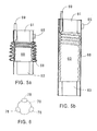
- the conduit 40 and the tube 48 are both concentric and similarly shaped, in the form of folds 47, by example.
- Reinforcements or more rigid zones can be provided at the level of the folds to properly mark the folds and ensure the reproducibility of the unfolding and re-folding the hose. These reinforcement areas can also reduce the tendency of the duct 40 to close on itself under the effect of the depression.
- ends 42 and 44 of the tube are respectively fixed to the rigid parts 41 and 43 of the downstream and upstream ducts of the aeraulic circuit suction.
- the ends 42 are connected to the booster group of the tube, while the ends 44 are closed.
- a valve 45 allows air evacuation when the user wishes to fold the hose.
- These connections can take various forms, such as that already mentioned: a helicoid, rings, ... or even more random, in order to present an isotropic or anisotropic flexibility. In this idea, it can indeed be comfortable for the user to use a flexible having a fairly high rigidity in a particular direction, and less important in another direction.
- the present invention can also be implemented using a conduit of the "strech-hose" type as previously described.
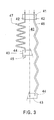
- Figure 4 shows such configuration, the right part of said figure showing the elongated hose, while the left side represents it in the folded state.
- Such a conduit 50 therefore comprises a flexible envelope 51 inside of which is arranged a mechanical reinforcement in the form of a spring wire 55.
- the wire used can be a metal wire or a plastic wire.
- the tube is glued or welded to the flexible envelope 51 at the areas 59 of contact of the spring wire 55 with said flexible envelope 51.
- the flexible tube is a tube identical to tube 8 previously mentioned and wound in a helix, alternately and parallel to the metallic wire 55.
- the conduit 50 By sending overpressured air into the tube 58, the conduit 50 is forced to lengthen by spreading the turns of the metal wire 55.
- the interest, according to this configuration, is not to stiffen the hose, but rather to produce a force opposing the return force of the spring wire 55, which makes it possible to avoid the disadvantage of an unexpected return of the hose to the frame of the device, or Conversely.
- said flexible conduit 60 is connected to the rigid parts 63 and 61 located respectively upstream and downstream of said suction duct.
- a flexible tube 68 is arranged concentrically with said conduit while being held mechanically and tightly to the rigid parts 61 and 63.
- a channel 69 connects the flexible tube 68 to the vacuum group of said tube.
- the tube 68 In operation, when the tube 68 is inflated with air or any other fluid, it tends to lengthen and move away from one another the rigid parts 61 and 63; of this fact, the conduit 60 elongates.
- This configuration is preferably adapted to allow the realization of a particularly rigid duct.
- the diameter of the tube and / or the value of the overpressure can even be adjusted to obtain rigidity and behavior of the duct close to rigid metallic or plastic tubes.
- the present invention is not limited to the various variants proposed and particular to the proposed arrangements, but also covers mutually compatible combinations of said variants.
- the tube can be arranged longitudinally, being parallel to the conduit, as shown in section, Figure 6, where the conduit 70 is surrounded by three tubes 78.
- the present invention is not limited, in this configuration, when using three tubes arranged around the duct, the number of tubes used depending on the desired stiffness / flexibility characteristics.
Landscapes
- Engineering & Computer Science (AREA)
- Mechanical Engineering (AREA)
- Electric Vacuum Cleaner (AREA)
Abstract
Description
- les figures 1a et 1b présentent schématiquement l'invention selon l'un des modes de réalisation possibles, où le tube est respectivement à l'état dégonflé et à l'état gonflé,
- les figures 2a et 2b présentent une variante de réalisation de l'invention, où le tube est concentrique au conduit souple, ledit tube étant respectivement présenté à l'état dégonflé et à l'état gonflé,
- la figure 3 illustre une autre variante de réalisation de la présente invention, la partie à gauche de l'axe de symétrie du conduit représentant le conduit et le tube dégonflé, tandis que la partie droite de la figure le représente gonflé,
- la figure 4 représente un autre mode de réalisation de l'invention, la partie à gauche de l'axe de symétrie du conduit représentant le tube et le conduit à l'état plié, tandis que la partie droite de la figure les représente à l'état déplié,
- les figures 5a et 5b représentent une variante de mise en oeuvre de l'invention, où le tube et le conduit sont respectivement présentés à l'état plié et à l'état déplié,
- la figure 6 présente, dans une vue en coupe, une variante de réalisation de la présente invention,
- la figure 7 illustre l'art antérieur.
Claims (24)
- Moyen de raidissement d'un conduit souple étanche (2, 30, 40, 50, 60, 70) constituant une portion du circuit aéraulique d'aspiration d'un appareil électrique de récupération de poussières de type aspirateur, ledit aspirateur comportant notamment un groupe d'aspiration susceptible de créer un flux d'aspiration dans ledit circuit aéraulique d'aspiration, ledit circuit aéraulique comprenant des parties rigides (41, 43, 61, 63) en amont et en aval du conduit souple (2, 30, 40, 50, 60, 70), caractérisé en ce que ce moyen de raidissement comprend un tube souple (8, 38, 48, 58, 68, 78) agencé soit longitudinalement sur ledit conduit souple, soit telle une hélicoïde autour dudit conduit souple (2, 30, 40, 50, 60, 70), ledit tube étant susceptible d'être gonflé par un fluide en surpression.
- Tube souple (8, 78) selon la revendication précédente, caractérisé en ce qu'il est réalisé par une bande de matériau de type plastique ou tissu étanche repliée et collée sur elle-même.
- Tube souple (8, 38, 48, 58, 68, 78) selon l'une des revendications précédentes, caractérisé en ce qu'il est réalisé au moins partiellement en un matériau légèrement extensible.
- Tube souple (8, 38, 58, 78) selon l'une des revendications précédentes, caractérisé en ce qu'il est fixé audit conduit (2, 30, 50, 70) par soudure ou par collage.
- Tube souple (8, 38, 58, 78) selon la revendication précédente, caractérisé en ce que la soudure ou le collage du tube au conduit (2, 30, 50, 70) est conformé selon une bande en hélicoïde.
- Tube souple (8, 38, 58, 78) selon la revendication précédente, caractérisé en ce qu'il est solidarisé sur le conduit souple (2, 30, 50, 70) par l'intermédiaire d'une languette.
- Tube souple (48, 68) selon l'une des revendications 1 à 3, caractérisé en ce qu'il est fixé sur les parties rigides (41, 43, 61, 63) du circuit aéraulique situées en amont et en aval du conduit souple (40, 60).
- Tube souple (8, 38, 48, 58, 68, 78) selon l'une des revendications précédentes, caractérisé en ce que le fluide utilisé est de l'air.
- Tube souple (8, 38, 48, 58, 68, 78) selon la revendication précédente, caractérisé en ce que la mise en surpression dudit tube est indépendante du groupe d'aspiration.
- Tube souple (8, 38, 48, 58, 68, 78) selon l'une des revendications 1 à 8, caractérisé en ce que la mise en surpression dudit tube est obtenue par dérivation du flux d'air sortant du groupe d'aspiration.
- Tube souple (8, 38, 48, 58, 68, 78) selon l'une des revendications 1 à 7, caractérisé en ce que le fluide utilisé est un liquide.
- Tube souple (8, 38, 48, 58, 68, 78) selon l'une des revendications précédentes, caractérisé en ce qu'il est réalisé en un tissu étanche.
- Tube souple (38, 48, 58, 68) selon l'une des revendications 4 à 12, caractérisé en ce qu'il est concentrique au conduit souple (30, 40, 50, 60).
- Portion d'un circuit aéraulique d'aspiration d'un appareil électrique de récupération de poussières de type aspirateur, ledit aspirateur comportant notamment un groupe d'aspiration susceptible de créer un flux d'aspiration dans ledit circuit aéraulique d'aspiration, caractérisée en ce qu'elle est constituée d'un conduit souple (2, 30, 40, 50, 60, 70) autour duquel est agencé un moyen de raidissement (8, 38, 48, 58, 68, 78) selon l'une des revendications 1 à 13.
- Portion de circuit aéraulique selon la revendication précédente, caractérisée en ce que la surface interne du conduit souple (2, 30, 40, 50, 60, 70) est lisse.
- Portion de circuit aéraulique selon l'une des revendications 14 ou 15, caractérisée en ce qu'elle comporte un second moyen de raidissement selon l'une des revendications 1 à 12, indépendant du premier (8, 38, 48, 58, 68, 78).
- Portion de circuit aéraulique selon la revendication précédente, caractérisé en ce que le second moyen de raidissement est agencé de façon alternée avec ledit premier moyen de raidissement (8, 38, 58, 78).
- Portion de circuit aéraulique d'aspiration d'un appareil électrique de récupération de poussières de type aspirateur, ledit aspirateur comportant notamment un groupe d'aspiration susceptible de créer un flux d'aspiration dans ledit circuit aéraulique d'aspiration, ladite portion de circuit aéraulique étant constituée d'un conduit souple (40, 50) autour duquel est agencé un tube souple (48, 58) selon la revendication 13, caractérisée en ce que le tube souple (48, 58) et le conduit souple (40, 50) sont tous les deux plissés selon la même conformation.
- Portion de circuit aéraulique d'aspiration d'un appareil électrique de récupération de poussières de type aspirateur, ledit aspirateur comportant notamment un groupe d'aspiration susceptible de créer un flux d'aspiration dans ledit circuit aéraulique d'aspiration, ladite portion de circuit aéraulique étant constituée d'un conduit souple (50, 60) autour duquel est agencé un tube souple (58, 68) selon la revendication 13, caractérisée en ce que le conduit souple (50, 60) est constitué d'une paroi souple armée par un fil métallique ou plastique (55) formé en spirale et possédant un effet ressort.
- Portion de circuit aéraulique d'aspiration selon la revendication précédente, caractérisé en ce que le tube souple (58, 68) peut être gonflé par une surpression susceptible de générer une force supérieure à la force de rappel du fil métallique ou plastique (55) allongé.
- Portion de circuit aéraulique d'aspiration selon l'une des revendications 14 à 20, caractérisé en ce que le tube (8, 38, 48, 58, 68, 78) et le conduit (2, 30, 40, 50, 60, 70) sont réalisés par extrusion ou par soufflage.
- Appareil de récupération des déchets de type aspirateur, comportant notamment un groupe d'aspiration permettant de créer une dépression dans un circuit aéraulique relié à la surface à nettoyer, ainsi qu'un moyen de séparation des déchets, caractérisé en ce qu'une portion dudit circuit aéraulique est conforme à l'une des revendications 14 à 21.
- Appareil de récupération des déchets selon la revendication précédente, caractérisé en ce que le circuit de gonflage du tube souple (8, 38, 48, 58, 68, 78) comprend une soupape d'évacuation du fluide utilisé.
- Appareil de récupération des déchets selon l'une des revendications 22 ou 23, caractérisé en ce qu'il comporte un moyen de réglage de la surpression dans le tube souple (8, 38, 48, 58, 68, 78).
Applications Claiming Priority (2)
| Application Number | Priority Date | Filing Date | Title |
|---|---|---|---|
| FR0104991 | 2001-04-11 | ||
| FR0104991A FR2823431B1 (fr) | 2001-04-11 | 2001-04-11 | Tuyau flexible gonflable pour aspirateur |
Publications (1)
| Publication Number | Publication Date |
|---|---|
| EP1249200A1 true EP1249200A1 (fr) | 2002-10-16 |
Family
ID=8862247
Family Applications (1)
| Application Number | Title | Priority Date | Filing Date |
|---|---|---|---|
| EP02356062A Withdrawn EP1249200A1 (fr) | 2001-04-11 | 2002-04-03 | Tuyau flexible gonflable pour aspirateur |
Country Status (2)
| Country | Link |
|---|---|
| EP (1) | EP1249200A1 (fr) |
| FR (1) | FR2823431B1 (fr) |
Cited By (2)
| Publication number | Priority date | Publication date | Assignee | Title |
|---|---|---|---|---|
| CN102188210A (zh) * | 2010-03-09 | 2011-09-21 | 乐金电子(天津)电器有限公司 | 充气式直管 |
| CN102327098A (zh) * | 2011-06-23 | 2012-01-25 | 太仓南极风能源设备有限公司 | 吸尘器吸尘管 |
Citations (4)
| Publication number | Priority date | Publication date | Assignee | Title |
|---|---|---|---|---|
| EP0279344A2 (fr) * | 1987-02-19 | 1988-08-24 | Vohran Patentverwertungs-Gmbh | Tuyau flexible |
| EP0788759A2 (fr) * | 1996-02-08 | 1997-08-13 | Dual-Voltage Co. Ltd. | Noyau flexible en plastique |
| GB2323422A (en) * | 1997-03-21 | 1998-09-23 | Vax Ltd | Coiled tubing |
| DE29911311U1 (de) * | 1999-06-29 | 1999-11-18 | Sieber, Bernd, 35394 Gießen | Schlauch und Staubsauger mit einem derartigen Schlauch |
-
2001
- 2001-04-11 FR FR0104991A patent/FR2823431B1/fr not_active Expired - Fee Related
-
2002
- 2002-04-03 EP EP02356062A patent/EP1249200A1/fr not_active Withdrawn
Patent Citations (4)
| Publication number | Priority date | Publication date | Assignee | Title |
|---|---|---|---|---|
| EP0279344A2 (fr) * | 1987-02-19 | 1988-08-24 | Vohran Patentverwertungs-Gmbh | Tuyau flexible |
| EP0788759A2 (fr) * | 1996-02-08 | 1997-08-13 | Dual-Voltage Co. Ltd. | Noyau flexible en plastique |
| GB2323422A (en) * | 1997-03-21 | 1998-09-23 | Vax Ltd | Coiled tubing |
| DE29911311U1 (de) * | 1999-06-29 | 1999-11-18 | Sieber, Bernd, 35394 Gießen | Schlauch und Staubsauger mit einem derartigen Schlauch |
Cited By (2)
| Publication number | Priority date | Publication date | Assignee | Title |
|---|---|---|---|---|
| CN102188210A (zh) * | 2010-03-09 | 2011-09-21 | 乐金电子(天津)电器有限公司 | 充气式直管 |
| CN102327098A (zh) * | 2011-06-23 | 2012-01-25 | 太仓南极风能源设备有限公司 | 吸尘器吸尘管 |
Also Published As
| Publication number | Publication date |
|---|---|
| FR2823431A1 (fr) | 2002-10-18 |
| FR2823431B1 (fr) | 2003-07-25 |
Similar Documents
| Publication | Publication Date | Title |
|---|---|---|
| CN1292698C (zh) | 真空吸尘器装置及其软管 | |
| EP1121953B1 (fr) | Appareil d'assistance respiratoire | |
| JP2002065534A (ja) | 可撓性ホース及び可撓性ホースを有する真空クリーナ装置 | |
| EP0693433A2 (fr) | Emballage distributeur pour produit pâteux et procédé de fabrication d'un tel emballage | |
| EP0031981B1 (fr) | Procédé de réalisation d'une enveloppe de ballon, en particulier pour ballons spatiaux, enveloppe réalisée, et utilisation de celle-ci dans le domaine aérospatial | |
| FR2855389A1 (fr) | Collecteur de poussiere a cyclone et ensemble formant poignee pour un aspirateur | |
| EP1233731A1 (fr) | Dispositif de remplacement d'une valve cardiaque par voie percutanee | |
| EP1067857B1 (fr) | Appareil electrique recuperateur de dechets | |
| CH364622A (fr) | Tambour de confection de pneumatiques | |
| WO2013182608A1 (fr) | Dispositif portatif de gonflage d'un pneu de velo, notamment un pneu tubeless | |
| FR2823431A1 (fr) | Tuyau flexible gonflable pour aspirateur | |
| FR2870112A1 (fr) | Poche de recueil pour stomie a fermeture par pli vertical | |
| WO2022129519A1 (fr) | Gaine flexible en éversion creuse | |
| FR2773717A1 (fr) | Catheter pour canal corporel | |
| EP3181914B1 (fr) | Article gonflable par effet venturi | |
| FR2585771A1 (fr) | Procede de fabrication d'un cone de sortie de tuyere extensible de moteur-fusee et cette tuyere | |
| FR2679423A1 (fr) | Parapluie de poche. | |
| WO2025237981A1 (fr) | Ensemble gonflable | |
| EP4623170A1 (fr) | Structure gonflable et procede de fabrication d'une structure gonflable | |
| FR2874953A1 (fr) | Un dispositif pour permettre le maintien d'une piscine autoportee vide afin de la nettoyer et de la secher | |
| FR2864841A1 (fr) | Dispositif utilisant l'energie de la houle pour produire de l'air comprime | |
| FR3120925A1 (fr) | Dispositif d’actionnement fluidique comprenant au moins deux enveloppes souples, aile d’aéronef à profil variable intégrant au moins un tel dispositif et aéronef comprenant au moins une telle aile | |
| FR2889935A1 (fr) | Tuyau d'aspiration flexible de longueur variable | |
| WO2006120329A1 (fr) | Element tubulaire souple | |
| FR2852793A1 (fr) | Seche-cheveux equipe d'un manchon courbe |
Legal Events
| Date | Code | Title | Description |
|---|---|---|---|
| PUAI | Public reference made under article 153(3) epc to a published international application that has entered the european phase |
Free format text: ORIGINAL CODE: 0009012 |
|
| AK | Designated contracting states |
Kind code of ref document: A1 Designated state(s): AT BE CH CY DE DK ES FI FR GB GR IE IT LI LU MC NL PT SE TR |
|
| AX | Request for extension of the european patent |
Free format text: AL;LT;LV;MK;RO;SI |
|
| 17P | Request for examination filed |
Effective date: 20030324 |
|
| AKX | Designation fees paid |
Designated state(s): AT BE CH CY DE DK ES FI FR GB GR IE IT LI LU MC NL PT SE TR |
|
| 17Q | First examination report despatched |
Effective date: 20071109 |
|
| REG | Reference to a national code |
Ref country code: HK Ref legal event code: WD Ref document number: 1050125 Country of ref document: HK |
|
| STAA | Information on the status of an ep patent application or granted ep patent |
Free format text: STATUS: THE APPLICATION IS DEEMED TO BE WITHDRAWN |
|
| 18D | Application deemed to be withdrawn |
Effective date: 20141104 |