EP1248891B1 - Clamping body for fixing overlapping counterflashings - Google Patents
Clamping body for fixing overlapping counterflashings Download PDFInfo
- Publication number
- EP1248891B1 EP1248891B1 EP01910204A EP01910204A EP1248891B1 EP 1248891 B1 EP1248891 B1 EP 1248891B1 EP 01910204 A EP01910204 A EP 01910204A EP 01910204 A EP01910204 A EP 01910204A EP 1248891 B1 EP1248891 B1 EP 1248891B1
- Authority
- EP
- European Patent Office
- Prior art keywords
- strip
- counterflashings
- lead
- clamping body
- converging
- Prior art date
- Legal status (The legal status is an assumption and is not a legal conclusion. Google has not performed a legal analysis and makes no representation as to the accuracy of the status listed.)
- Expired - Lifetime
Links
- 239000000463 material Substances 0.000 claims abstract description 8
- XLYOFNOQVPJJNP-UHFFFAOYSA-N water Substances O XLYOFNOQVPJJNP-UHFFFAOYSA-N 0.000 claims description 6
- 239000012858 resilient material Substances 0.000 abstract description 2
- 239000004568 cement Substances 0.000 abstract 1
- 229910000639 Spring steel Inorganic materials 0.000 description 1
- 238000010276 construction Methods 0.000 description 1
- 230000000284 resting effect Effects 0.000 description 1
- 229910001220 stainless steel Inorganic materials 0.000 description 1
- 239000010935 stainless steel Substances 0.000 description 1
Images

Classifications
-
- E—FIXED CONSTRUCTIONS
- E04—BUILDING
- E04D—ROOF COVERINGS; SKY-LIGHTS; GUTTERS; ROOF-WORKING TOOLS
- E04D13/00—Special arrangements or devices in connection with roof coverings; Protection against birds; Roof drainage ; Sky-lights
- E04D13/14—Junctions of roof sheathings to chimneys or other parts extending above the roof
- E04D13/147—Junctions of roof sheathings to chimneys or other parts extending above the roof specially adapted for inclined roofs
- E04D13/1478—Junctions to walls extending above the roof
-
- E—FIXED CONSTRUCTIONS
- E04—BUILDING
- E04D—ROOF COVERINGS; SKY-LIGHTS; GUTTERS; ROOF-WORKING TOOLS
- E04D13/00—Special arrangements or devices in connection with roof coverings; Protection against birds; Roof drainage ; Sky-lights
- E04D13/14—Junctions of roof sheathings to chimneys or other parts extending above the roof
- E04D13/1407—Junctions of roof sheathings to chimneys or other parts extending above the roof for flat roofs
- E04D13/1415—Junctions to walls extending above the perimeter of the roof
Definitions
- the invention is related to a clamping body for fixing overlapping counterflashings which serve to enable water to be discharged at joints between a sloping roof surface and a vertical wall, which clamping body consists of resilient sheet material which has been bent to produce an article having two converging sections each having an end edge and two opposite side edges, as well as a strip connected to the end edge of one of the converging sections, which strip has an essentially perpendicular position with respect to that converging strip.
- Overlapping counterflashings made of lead or lead replacing material to enable proper discharge of water at joints between a sloping roof surface and a vertical wall are known. Such flashings overlap each other at their side edge. In addition they overlap with their lower edge the vertical upper part of a lead flashing resting with its lower edge on an oblique tiled roof. Water to be discharged flows via the overlapping counterflashings on the lead flashing and from this lead flashing on the tiled roof.
- a problem is that overlapping counterflashings may be bent upwards by the wind which may lead to leakage.
- the aim of the invention is to overcome this disadvantage. Therefore the strip projects laterally with respect to a side edge of that converging strip.
- U- or V-shaped clamping bodies having two converging sections of resilient material and being meant for fixing that part of a flashing made of lead or lead replacing material which is inserted into a joint between two structural components are also known from GB-A-2,316,959. These known clamping bodies do - however - not have a strip which projects laterally.
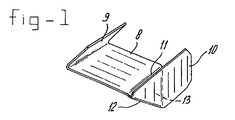
- Figure 1 shows a clamping body to be used to fix overlapping counterflashings serving to enable water to be discharged well at a join between the sloping roof surface and a vertical wall.
- Figure 2 shows a brickwork chimney that adjoins a sloping roof section where clamping bodies according to figure 1 have been used to fix the overlapping counterflashings.
- the clamping body shown in figure 1 made of spring steel or stainless steel is provided with a bottom strip 8 and an upper strip 9 extending obliquely upwards from an end edge of the bottom strip 8.
- a strip 10 is adjoined to the clamping body via two folds 11 and 12 and an intermediate strip 13 extending perpendicular to strip 8.
- This strip 10 also extends essentially perpendicular to the lower strip 8 and possesses a part which projects laterally with respect to a side edge of strip 8.
- This clamping body is used in the manner shown in figure 2.
- 15 indicates a cavity wall of a vertical chimney, which adjoins sloping tiled roof 16.
- the cavity has been given the reference number 17.
- Stepped counterflashings 18 made of lead or lead replacing material are arranged overlapping one another at 19 and have a vertical section 18a, a section 18b, that extends into a horizontal joint in the chimney wall, an upward sloping section 18c in the cavity of the chimney wall and a section 18d running in a joint located higher.
- clamping bodies according to the embodiment in figure 1 are fitted in the horizontal joint at the location of the overlaps 19.
- the laterally projecting section 10 holds the overlapping sections of the stepped counterflashings 18 in place well.
- the stepped counterflashings 18 will extend approximately to the middle of the section 18b.
- That part of the clamping body which consists of strips 8 and 9 may have the shape of a V, W and a U, whereas also shapes derived therefrom fall within the scope of the invention.
Landscapes
- Engineering & Computer Science (AREA)
- Architecture (AREA)
- Civil Engineering (AREA)
- Structural Engineering (AREA)
- Roof Covering Using Slabs Or Stiff Sheets (AREA)
- Sealing Battery Cases Or Jackets (AREA)
- Joining Of Building Structures In Genera (AREA)
- Mutual Connection Of Rods And Tubes (AREA)
Abstract
Description
Claims (1)
- Clamping body for fixing overlapping counterflashings which serve to enable water to be discharged at joints between a sloping roof surface and a vertical wall, which clamping body consists of resilient sheet material which has been bent to produce an article having two converging sections (8, 9) each having an end edge and two opposite side edges, as well as a strip (10) connected to the end edge of one (8) of the converging sections (8, 9) which strip (10) has an essentially perpendicular position with respect to that converging strip (8), characterized in that said strip (10) projects laterally with respect to a side edge of that converging strip (8).
Applications Claiming Priority (3)
| Application Number | Priority Date | Filing Date | Title |
|---|---|---|---|
| NL1014124 | 2000-01-19 | ||
| NL1014124A NL1014124C2 (en) | 2000-01-19 | 2000-01-19 | Clamping body for securing overlap counters. |
| PCT/NL2001/000039 WO2001053626A1 (en) | 2000-01-19 | 2001-01-19 | Method for fixing that part of a flashing, made of lead-replacement material, that is fitted in a joint between two structural components, and clamping body to be used for this |
Publications (2)
| Publication Number | Publication Date |
|---|---|
| EP1248891A1 EP1248891A1 (en) | 2002-10-16 |
| EP1248891B1 true EP1248891B1 (en) | 2004-05-19 |
Family
ID=19770630
Family Applications (1)
| Application Number | Title | Priority Date | Filing Date |
|---|---|---|---|
| EP01910204A Expired - Lifetime EP1248891B1 (en) | 2000-01-19 | 2001-01-19 | Clamping body for fixing overlapping counterflashings |
Country Status (6)
| Country | Link |
|---|---|
| EP (1) | EP1248891B1 (en) |
| AT (1) | ATE267314T1 (en) |
| AU (1) | AU2001237784A1 (en) |
| DE (1) | DE60103362T2 (en) |
| NL (1) | NL1014124C2 (en) |
| WO (1) | WO2001053626A1 (en) |
Families Citing this family (3)
| Publication number | Priority date | Publication date | Assignee | Title |
|---|---|---|---|---|
| GB2421253B (en) * | 2004-12-15 | 2006-11-29 | James Walter Egercz | Fixing clip |
| GB2470905A (en) * | 2009-06-08 | 2010-12-15 | Drive Elite Ltd | Flashing wedge |
| GB2499212A (en) * | 2012-02-08 | 2013-08-14 | Sabetoflex Aps | Flashing for corrugated roofing |
Family Cites Families (7)
| Publication number | Priority date | Publication date | Assignee | Title |
|---|---|---|---|---|
| US1537826A (en) * | 1924-01-25 | 1925-05-12 | Harry F Bryant | Flashing plug |
| US1905017A (en) * | 1931-09-03 | 1933-04-25 | Vallas Lionel | Roof flashing |
| DE1963213A1 (en) * | 1969-03-19 | 1970-09-24 | Schulte Stemmerk Kg | W-shaped seal for expansion joint |
| GB1357447A (en) * | 1971-06-10 | 1974-06-19 | Plastestrip Ltd | Spring clips for joint cover strips |
| GB2146678B (en) * | 1983-09-13 | 1987-01-07 | John Longworth | Wedge for retaining flashing |
| US4912900A (en) * | 1989-01-06 | 1990-04-03 | Yeamans Robert C | Perimeter securement assembly for roof deck covering |
| GB2316959B (en) * | 1996-07-27 | 2000-09-27 | James Hall | Roofing accessory |
-
2000
- 2000-01-19 NL NL1014124A patent/NL1014124C2/en not_active IP Right Cessation
-
2001
- 2001-01-19 AU AU2001237784A patent/AU2001237784A1/en not_active Abandoned
- 2001-01-19 EP EP01910204A patent/EP1248891B1/en not_active Expired - Lifetime
- 2001-01-19 AT AT01910204T patent/ATE267314T1/en not_active IP Right Cessation
- 2001-01-19 DE DE60103362T patent/DE60103362T2/en not_active Expired - Fee Related
- 2001-01-19 WO PCT/NL2001/000039 patent/WO2001053626A1/en not_active Ceased
Also Published As
| Publication number | Publication date |
|---|---|
| DE60103362T2 (en) | 2005-06-23 |
| DE60103362D1 (en) | 2004-06-24 |
| ATE267314T1 (en) | 2004-06-15 |
| EP1248891A1 (en) | 2002-10-16 |
| AU2001237784A1 (en) | 2001-07-31 |
| WO2001053626A1 (en) | 2001-07-26 |
| NL1014124C2 (en) | 2001-07-25 |
Similar Documents
| Publication | Publication Date | Title |
|---|---|---|
| US7752812B2 (en) | Integrated debris-shielding cover, flashing & mounting system for rain gutter | |
| US4803816A (en) | Roofing slab | |
| US6457279B1 (en) | Flashing member and frame for a roof-penetrating building part | |
| JPH02501230A (en) | Sealing devices for frontages and/or roofs | |
| FR2789460B1 (en) | HOMOCINETIC JOINT OF WHICH THE COMPONENTS ARE PRODUCED FROM SHEET | |
| US20020152691A1 (en) | Internal corner roof gutters | |
| SK6802000A3 (en) | A kit made from sheet material for flashing a quadrangular roof-penetrating element and a method of flashing a quadrangular element | |
| US8117785B2 (en) | Gutter system | |
| US20060225368A1 (en) | Rainwater gutter and eave trough repair system | |
| NL1014124C2 (en) | Clamping body for securing overlap counters. | |
| US1804315A (en) | Roof flashing | |
| ATE57411T1 (en) | INLET POT FOR ROOF DRAIN RAINWATER AND INSERT PART FOR SUCH. | |
| ITMI20090109U1 (en) | MOUNTING KIT FOR LAYING AND / OR INSTALLATION OF CONSTRUCTIONS OVER THE ROOF | |
| US4263756A (en) | Building element | |
| JP2010236282A (en) | Gable cover and building | |
| JP2008115662A (en) | Curtain wall structure of building | |
| GB2084209A (en) | Repairing gutters | |
| AU714994B2 (en) | A gutter system | |
| GB2401615A (en) | Roof edging strip | |
| AU722055B2 (en) | Improved flashing | |
| JP3338111B2 (en) | Water leakage prevention structure for cubic joints in the curtain wall of the roof. | |
| US853657A (en) | Roof for mausoleums, vaults, &c. | |
| SE502889C2 (en) | Shaped beam for masonry over window and door openings | |
| JP2554761Y2 (en) | Rain cut structure of wall panel and gutter connector used for the rain cut structure | |
| AU669285B2 (en) | A roof gutter |
Legal Events
| Date | Code | Title | Description |
|---|---|---|---|
| PUAI | Public reference made under article 153(3) epc to a published international application that has entered the european phase |
Free format text: ORIGINAL CODE: 0009012 |
|
| 17P | Request for examination filed |
Effective date: 20020722 |
|
| AK | Designated contracting states |
Kind code of ref document: A1 Designated state(s): AT BE CH CY DE DK ES FI FR GB GR IE IT LI LU MC NL PT SE TR |
|
| AX | Request for extension of the european patent |
Free format text: AL;LT;LV;MK;RO;SI |
|
| 17Q | First examination report despatched |
Effective date: 20030303 |
|
| GRAP | Despatch of communication of intention to grant a patent |
Free format text: ORIGINAL CODE: EPIDOSNIGR1 |
|
| RTI1 | Title (correction) |
Free format text: CLAMPING BODY FOR FIXING OVERLAPPING COUNTERFLASHINGS |
|
| GRAA | (expected) grant |
Free format text: ORIGINAL CODE: 0009210 |
|
| GRAS | Grant fee paid |
Free format text: ORIGINAL CODE: EPIDOSNIGR3 |
|
| AK | Designated contracting states |
Kind code of ref document: B1 Designated state(s): AT BE CH CY DE DK ES FI FR GB GR IE IT LI LU MC NL PT SE TR |
|
| PG25 | Lapsed in a contracting state [announced via postgrant information from national office to epo] |
Ref country code: IT Free format text: LAPSE BECAUSE OF FAILURE TO SUBMIT A TRANSLATION OF THE DESCRIPTION OR TO PAY THE FEE WITHIN THE PRESCRIBED TIME-LIMIT;WARNING: LAPSES OF ITALIAN PATENTS WITH EFFECTIVE DATE BEFORE 2007 MAY HAVE OCCURRED AT ANY TIME BEFORE 2007. THE CORRECT EFFECTIVE DATE MAY BE DIFFERENT FROM THE ONE RECORDED. Effective date: 20040519 Ref country code: AT Free format text: LAPSE BECAUSE OF FAILURE TO SUBMIT A TRANSLATION OF THE DESCRIPTION OR TO PAY THE FEE WITHIN THE PRESCRIBED TIME-LIMIT Effective date: 20040519 Ref country code: TR Free format text: LAPSE BECAUSE OF FAILURE TO SUBMIT A TRANSLATION OF THE DESCRIPTION OR TO PAY THE FEE WITHIN THE PRESCRIBED TIME-LIMIT Effective date: 20040519 Ref country code: FI Free format text: LAPSE BECAUSE OF FAILURE TO SUBMIT A TRANSLATION OF THE DESCRIPTION OR TO PAY THE FEE WITHIN THE PRESCRIBED TIME-LIMIT Effective date: 20040519 Ref country code: LI Free format text: LAPSE BECAUSE OF FAILURE TO SUBMIT A TRANSLATION OF THE DESCRIPTION OR TO PAY THE FEE WITHIN THE PRESCRIBED TIME-LIMIT Effective date: 20040519 Ref country code: CH Free format text: LAPSE BECAUSE OF FAILURE TO SUBMIT A TRANSLATION OF THE DESCRIPTION OR TO PAY THE FEE WITHIN THE PRESCRIBED TIME-LIMIT Effective date: 20040519 |
|
| REG | Reference to a national code |
Ref country code: GB Ref legal event code: FG4D |
|
| REG | Reference to a national code |
Ref country code: CH Ref legal event code: EP |
|
| REG | Reference to a national code |
Ref country code: IE Ref legal event code: FG4D |
|
| REF | Corresponds to: |
Ref document number: 60103362 Country of ref document: DE Date of ref document: 20040624 Kind code of ref document: P |
|
| PG25 | Lapsed in a contracting state [announced via postgrant information from national office to epo] |
Ref country code: SE Free format text: LAPSE BECAUSE OF FAILURE TO SUBMIT A TRANSLATION OF THE DESCRIPTION OR TO PAY THE FEE WITHIN THE PRESCRIBED TIME-LIMIT Effective date: 20040819 Ref country code: GR Free format text: LAPSE BECAUSE OF FAILURE TO SUBMIT A TRANSLATION OF THE DESCRIPTION OR TO PAY THE FEE WITHIN THE PRESCRIBED TIME-LIMIT Effective date: 20040819 Ref country code: DK Free format text: LAPSE BECAUSE OF FAILURE TO SUBMIT A TRANSLATION OF THE DESCRIPTION OR TO PAY THE FEE WITHIN THE PRESCRIBED TIME-LIMIT Effective date: 20040819 |
|
| PG25 | Lapsed in a contracting state [announced via postgrant information from national office to epo] |
Ref country code: ES Free format text: LAPSE BECAUSE OF FAILURE TO SUBMIT A TRANSLATION OF THE DESCRIPTION OR TO PAY THE FEE WITHIN THE PRESCRIBED TIME-LIMIT Effective date: 20040830 |
|
| LTIE | Lt: invalidation of european patent or patent extension |
Effective date: 20040519 |
|
| REG | Reference to a national code |
Ref country code: CH Ref legal event code: PL |
|
| PG25 | Lapsed in a contracting state [announced via postgrant information from national office to epo] |
Ref country code: IE Free format text: LAPSE BECAUSE OF NON-PAYMENT OF DUE FEES Effective date: 20050119 Ref country code: LU Free format text: LAPSE BECAUSE OF NON-PAYMENT OF DUE FEES Effective date: 20050119 Ref country code: CY Free format text: LAPSE BECAUSE OF FAILURE TO SUBMIT A TRANSLATION OF THE DESCRIPTION OR TO PAY THE FEE WITHIN THE PRESCRIBED TIME-LIMIT Effective date: 20050119 |
|
| PGFP | Annual fee paid to national office [announced via postgrant information from national office to epo] |
Ref country code: GB Payment date: 20050119 Year of fee payment: 5 |
|
| PG25 | Lapsed in a contracting state [announced via postgrant information from national office to epo] |
Ref country code: MC Free format text: LAPSE BECAUSE OF NON-PAYMENT OF DUE FEES Effective date: 20050131 |
|
| ET | Fr: translation filed | ||
| PGFP | Annual fee paid to national office [announced via postgrant information from national office to epo] |
Ref country code: BE Payment date: 20050302 Year of fee payment: 5 |
|
| PLBE | No opposition filed within time limit |
Free format text: ORIGINAL CODE: 0009261 |
|
| STAA | Information on the status of an ep patent application or granted ep patent |
Free format text: STATUS: NO OPPOSITION FILED WITHIN TIME LIMIT |
|
| 26N | No opposition filed |
Effective date: 20050222 |
|
| PG25 | Lapsed in a contracting state [announced via postgrant information from national office to epo] |
Ref country code: DE Free format text: LAPSE BECAUSE OF NON-PAYMENT OF DUE FEES Effective date: 20050802 |
|
| PG25 | Lapsed in a contracting state [announced via postgrant information from national office to epo] |
Ref country code: FR Free format text: LAPSE BECAUSE OF NON-PAYMENT OF DUE FEES Effective date: 20050930 |
|
| REG | Reference to a national code |
Ref country code: IE Ref legal event code: MM4A |
|
| REG | Reference to a national code |
Ref country code: FR Ref legal event code: ST |
|
| PG25 | Lapsed in a contracting state [announced via postgrant information from national office to epo] |
Ref country code: GB Free format text: LAPSE BECAUSE OF NON-PAYMENT OF DUE FEES Effective date: 20060119 |
|
| PG25 | Lapsed in a contracting state [announced via postgrant information from national office to epo] |
Ref country code: BE Free format text: LAPSE BECAUSE OF NON-PAYMENT OF DUE FEES Effective date: 20060131 |
|
| GBPC | Gb: european patent ceased through non-payment of renewal fee |
Effective date: 20060119 |
|
| BERE | Be: lapsed |
Owner name: *BORRA HANS-ANTONIUS Effective date: 20060131 |
|
| PG25 | Lapsed in a contracting state [announced via postgrant information from national office to epo] |
Ref country code: PT Free format text: LAPSE BECAUSE OF NON-PAYMENT OF DUE FEES Effective date: 20041019 |
|
| PGFP | Annual fee paid to national office [announced via postgrant information from national office to epo] |
Ref country code: NL Payment date: 20151221 Year of fee payment: 16 |
|
| REG | Reference to a national code |
Ref country code: NL Ref legal event code: MM Effective date: 20170201 |
|
| PG25 | Lapsed in a contracting state [announced via postgrant information from national office to epo] |
Ref country code: NL Free format text: LAPSE BECAUSE OF NON-PAYMENT OF DUE FEES Effective date: 20170201 |