EP1248377A2 - Error correction encoding method and apparatus, and error correction decoding method and apparatus - Google Patents
Error correction encoding method and apparatus, and error correction decoding method and apparatus Download PDFInfo
- Publication number
- EP1248377A2 EP1248377A2 EP02006348A EP02006348A EP1248377A2 EP 1248377 A2 EP1248377 A2 EP 1248377A2 EP 02006348 A EP02006348 A EP 02006348A EP 02006348 A EP02006348 A EP 02006348A EP 1248377 A2 EP1248377 A2 EP 1248377A2
- Authority
- EP
- European Patent Office
- Prior art keywords
- frame
- reception
- transmission
- bit sequence
- information bit
- Prior art date
- Legal status (The legal status is an assumption and is not a legal conclusion. Google has not performed a legal analysis and makes no representation as to the accuracy of the status listed.)
- Withdrawn
Links
Images





Classifications
-
- H—ELECTRICITY
- H03—ELECTRONIC CIRCUITRY
- H03M—CODING; DECODING; CODE CONVERSION IN GENERAL
- H03M13/00—Coding, decoding or code conversion, for error detection or error correction; Coding theory basic assumptions; Coding bounds; Error probability evaluation methods; Channel models; Simulation or testing of codes
- H03M13/29—Coding, decoding or code conversion, for error detection or error correction; Coding theory basic assumptions; Coding bounds; Error probability evaluation methods; Channel models; Simulation or testing of codes combining two or more codes or code structures, e.g. product codes, generalised product codes, concatenated codes, inner and outer codes
- H03M13/2957—Turbo codes and decoding
- H03M13/2978—Particular arrangement of the component decoders
- H03M13/2987—Particular arrangement of the component decoders using more component decoders than component codes, e.g. pipelined turbo iterations
-
- H—ELECTRICITY
- H03—ELECTRONIC CIRCUITRY
- H03M—CODING; DECODING; CODE CONVERSION IN GENERAL
- H03M13/00—Coding, decoding or code conversion, for error detection or error correction; Coding theory basic assumptions; Coding bounds; Error probability evaluation methods; Channel models; Simulation or testing of codes
- H03M13/29—Coding, decoding or code conversion, for error detection or error correction; Coding theory basic assumptions; Coding bounds; Error probability evaluation methods; Channel models; Simulation or testing of codes combining two or more codes or code structures, e.g. product codes, generalised product codes, concatenated codes, inner and outer codes
- H03M13/2957—Turbo codes and decoding
-
- H—ELECTRICITY
- H03—ELECTRONIC CIRCUITRY
- H03M—CODING; DECODING; CODE CONVERSION IN GENERAL
- H03M13/00—Coding, decoding or code conversion, for error detection or error correction; Coding theory basic assumptions; Coding bounds; Error probability evaluation methods; Channel models; Simulation or testing of codes
- H03M13/29—Coding, decoding or code conversion, for error detection or error correction; Coding theory basic assumptions; Coding bounds; Error probability evaluation methods; Channel models; Simulation or testing of codes combining two or more codes or code structures, e.g. product codes, generalised product codes, concatenated codes, inner and outer codes
- H03M13/2957—Turbo codes and decoding
- H03M13/2978—Particular arrangement of the component decoders
- H03M13/2981—Particular arrangement of the component decoders using as many component decoders as component codes
-
- H—ELECTRICITY
- H03—ELECTRONIC CIRCUITRY
- H03M—CODING; DECODING; CODE CONVERSION IN GENERAL
- H03M13/00—Coding, decoding or code conversion, for error detection or error correction; Coding theory basic assumptions; Coding bounds; Error probability evaluation methods; Channel models; Simulation or testing of codes
- H03M13/37—Decoding methods or techniques, not specific to the particular type of coding provided for in groups H03M13/03 - H03M13/35
- H03M13/3776—Decoding methods or techniques, not specific to the particular type of coding provided for in groups H03M13/03 - H03M13/35 using a re-encoding step during the decoding process
-
- H—ELECTRICITY
- H03—ELECTRONIC CIRCUITRY
- H03M—CODING; DECODING; CODE CONVERSION IN GENERAL
- H03M13/00—Coding, decoding or code conversion, for error detection or error correction; Coding theory basic assumptions; Coding bounds; Error probability evaluation methods; Channel models; Simulation or testing of codes
- H03M13/29—Coding, decoding or code conversion, for error detection or error correction; Coding theory basic assumptions; Coding bounds; Error probability evaluation methods; Channel models; Simulation or testing of codes combining two or more codes or code structures, e.g. product codes, generalised product codes, concatenated codes, inner and outer codes
- H03M13/2957—Turbo codes and decoding
- H03M13/296—Particular turbo code structure
- H03M13/2963—Turbo-block codes, i.e. turbo codes based on block codes, e.g. turbo decoding of product codes
-
- H—ELECTRICITY
- H03—ELECTRONIC CIRCUITRY
- H03M—CODING; DECODING; CODE CONVERSION IN GENERAL
- H03M13/00—Coding, decoding or code conversion, for error detection or error correction; Coding theory basic assumptions; Coding bounds; Error probability evaluation methods; Channel models; Simulation or testing of codes
- H03M13/29—Coding, decoding or code conversion, for error detection or error correction; Coding theory basic assumptions; Coding bounds; Error probability evaluation methods; Channel models; Simulation or testing of codes combining two or more codes or code structures, e.g. product codes, generalised product codes, concatenated codes, inner and outer codes
- H03M13/2957—Turbo codes and decoding
- H03M13/296—Particular turbo code structure
- H03M13/2972—Serial concatenation using convolutional component codes
Definitions
- the present invention relates to an error correction encoding method and apparatus, and an error correction decoding method and apparatus. More particularly, it relates to a method and apparatus for encoding turbo codes as well as a method and apparatus for decoding turbo codes.
- Fig. 10 is a flow chart illustrating the known turbo encoding method using a turbo encoder which will be described later.
- ST71 designates a processing step for determining the block length N of an interleaver at the start of transmission.
- ST72 designates a processing step for preparing an interleaver pattern of the block length N.
- ST73 designates a processing step for initializing the value of each register 65 of a first convolutional encoder and the value of each register 66 of a second convolutional encoder.
- ST74 designates a processing step for buffering an information bit sequence u for one block.
- ST75 designates a processing step for performing turbo encoding with a turbo encoder 61, and outputting parity bit sequences p a and p b .
- ST76 designates a processing step for calculating tail bits t used to return the registers 65 and 66 to their initial values.
- ST77 designates a processing step for determining whether a frame being now processed is the last (final) one, and switching the processing operation.
- Fig. 11 illustrates the configuration of the turbo encoder used at the sending side for implementing the above-mentioned turbo encoding method.
- the turbo encoder generally designated at reference numeral 61, includes a first recursive systematic convolutional encoder 62 (hereinafter, referred to simply as a first convolutional encoder) for convolutionally encoding an information bit sequence u to output a parity bit sequence p a , an interleaver 63, a second recursive systematic convolutional encoder 64 (hereinafter, referred to simply as a second convolutional encoder) for convolutionally encoding the information bit sequence u, which has been permuted by the interleaver 63, thereby to output a parity bit sequence p b , the registers 65 of the first convolutional encoder 62, and the registers 66 of the second convolutional encoder 64.
- a first convolutional encoder for convolutionally encoding an information bit sequence u to output
- Fig. 12 is the configuration of the information bit sequence and the parity bit sequences which have been encoded by the known encoding method and each merged into one frame.
- 51 designates the information bit sequence u input to the turbo encoder 61.
- 52 designates the parity bit sequence p a output from the first convolutional encoder 62.
- 53 designates the parity bit sequence p b output from the second convolutional encoder 64.
- 54 designates tail bits t a, u for returning the registers in the first convolutional encoder 62 to their initial values.
- 56 designates tail bits t a, p for returning the registers in the first convolutional encoder 62 to their initial values.
- 55 designates tail bits t b, u for returning the registers in the second convolutional encoder 64 to their initial values.
- 57 designates tail bits t b, p for returning the registers in the second convolutional encoder 64 to their initial values.
- Fig. 13 illustrates the configuration of an iterative decoder used at the receiving side.
- a first soft-input and soft-output decoder 81 (hereinafter, referred to simply as a first decoder) is input with reception sequences x, y a , Z a, u , z a, p and priori information (logarithm of a priori probability ratio) La(u), and calculates log-likelihood ratio L(u) therefrom.
- a second soft-input and soft-output decoder 82 (hereinafter, referred to simply as a second decoder) is input with reception sequences x, y b , z b, u , z b, p , and priori information (logarithm of a priori probability ratio) La(u), and calculates log-likelihood ratio L(u).
- the iterative decoder further includes interleavers 83 and 84, a deinterleaver 85, a first adder 86, a second adder 87, a determiner 88 for calculating an estimate value of a transmitted information bit sequence from the log-likelihood ratio L(u) output from the second decoder 82, and a switch 89 for switching the priori probability La(u), which is input to the first decoder 81, to an initial value 0 or a value output from the second adder 87.
- Fig. 14 is a flow chart showing an MAP (maximum a posteriori) decoding method, which is one technique of a calculation means of the soft-input and soft-output decoder (i.e., the first decoder 81 and the second decoder 82) used at the receiving side.
- the time point k is initialized to 1 in step ST102.
- Branch metrics ⁇ i,k is calculated in step ST103.
- a forward path metric ⁇ (S j, k ) is calculated in step ST104.
- the forward path metric ⁇ (S j, k ) thus calculated is stored in a memory in step ST105. It is determined in step ST106 whether the time point k has become N or more. The time point k is incremented by 1 in step ST107.
- the branch metric ⁇ i, k is calculated in step ST110.
- the backward path metric ⁇ (S j, k ) is calculated in step ST104.
- Log-likelihood ratio L(u k ) is calculated in step ST112.
- An extrinsic information Le(u k ) is calculated in step ST112. It is determined in step ST114 whether the time point k has become 1 or less. The time point k is decremented by 1 in step ST115.
- An information bit sequence u: u 1 , u 2 , ⁇ , u N is successively input to the turbo encoder 61 shown in Fig. 11 in the order of time points 1, 2, ⁇ , N, respectively. That is, the first recursive systematic convolutional encoder 62 of the turbo encoder 61 encodes the information bit sequence u input thereto, and outputs a parity bit sequence p a : p a, 1 , p a, 2 , ⁇ , p a, N .
- the tail bits t a,u and the tail bits t a, p are calculated (here, the lengths of tail bits t a, u and t a, p are assumed to be T, respectively.).
- the tail bits can be uniquely calculated according to the values of the registers after the last information bit u N has been input.
- the registers are returned to their initial values when the tail bits t a, u are input to the first convolutional encoder 62.
- the first convolutional encoder 62 outputs the tail bits t a, p as parity bits.
- the second convolutional encoder 64 of the turbo encoder 61 successively encodes sequences of information bits u which have been permuted by the interleaver 63 and input thereto, and outputs the parity bit sequence p b : p b, 1 , p b, 2 , ⁇ , p b, N .
- the tail bits t b, u and the tail bits t b, p for returning the registers of the second convolutional encoder 64 to their initial values are calculated (the lengths of t b, u and t b, p are assumed to be T, respectively).
- the tail bits can be uniquely calculated according to the values of the registers after the last information bit u N has been input.
- the registers therein are returned to their initial values, and the second convolutional encoder 64 outputs the tail bits t b, p as parity bits.
- the information bit sequence u, the parity bit sequences p a , p b and the tail bits t a, u , t a, p , t b, u , t b, p are transmitted, as shown in Fig. 12.
- the information bit sequence u input to the second convolutional encoder 64 is required to be permuted by the interleaver 63. Therefore, it is necessary to divide the information bit sequence u into units of blocks of N in length.
- the interleaver 63 permutes the information bit sequences u 1 , u 2 , ⁇ , u N thus divided into the block units, respectively, of N in length.
- the information bit sequences, the parity bit sequences and the tail bit sequences finally encoded are transmitted in frames, as shown in Fig. 12.
- step ST71 the block length N in the interleaver 63 is decided in step ST71 as shown in Fig. 10.
- an interleaver pattern for the block length N is prepared in step ST72.
- the registers D of the convolutional encoders are initialized in step ST73.
- the turbo encoding processing is carried out to output parity bit sequences p a , p b in step ST75.
- Tail bits t are output in step ST76.
- step ST77 it is determined whether the transmission frame being now processed is the last one.
- step ST73 the registers D of the convolutional encoders are initialized, and the turbo encoding is continued.
- the transmission processing is terminated.
- reception sequence x which is the information bit sequence u being transmitted and added with noise on the transmission path or channel
- reception sequences y a and y b which are the parity bit sequences p a and p b being transmitted and added with noise on communication channels
- reception sequences z a, u , z a, p , z b, u , z b, p which are the tail bits being transmitted and added with noise on communication channels.
- reception sequences x: x 1 , x 2 , ⁇ , x N which are the information bit sequence u being transmitted and added with noise on communication channels
- a reception sequence y a y a, 1 , y a, 2 , ⁇ , y a, N which is the parity bit sequence p a being transmitted and added with noise on communication channels
- the reception sequence y b : y b, 1 , y b, 2 , ⁇ , y b, N which is the parity bit sequence p b being transmitted and added with noise on communication channels
- reception sequences z a, u , z a, p , z b, u , z b, p which are the tail bits t a, u , t a, p , t b, u, t
- the log-likelihood ratio: L(u k ) can be represented by the following expression (1).
- Le(u k ) represents extrinsic information
- La(u k ) represents the value which is calculated with one-preceding extrinsic information being taken as the priori information
- Pr(u' k 1
- ⁇ Y ⁇ ) represents a probability that the estimated information bits: u' k calculated with the whole sequence ⁇ Y ⁇ of the reception signal having been received are 1
- Pr(u' k 0
- the first adder 86 calculates the extrinsic information for the second decoder 82 from the log-likelihood ratio which are the result of above-mentioned calculations.
- Le ( u k ) L ( u k ) - Lc ⁇ x k - La ( u k )
- La(u k ) is equal to 0 in the first decoding because the a priori information has not been calculated.
- the interleavers 83 and 84 permute the reception sequence x and the sequence of extrinsic information Le(u k ) so as to match the time point of the reception sequence y b .
- the second decoder 82 calculates the log-likelihood ratio: L(u k ) based on the reception sequences x, y b , z b, u , z b, p and the extrinsic information: Le(u k ) previously calculated, as in the first decoder 81.
- the second adder 87 calculates the extrinsic information: Le(u k ) by using expression (2) above, as in the first adder 86.
- the extrinsic information permuted by the deinterleaver 85 is fed back to the first decoder 81 as the priori information: La(u k ).
- the iterative decoder calculates the log-likelihood ratio with higher accuracy by repeatedly executing the above-mentioned processing over a prescribed number of times.
- the determiner 89 makes a determination based on the log-likelihood ratio thus calculated thereby to estimate the original information bit sequence. Stated concretely, if the log-likelihood ratio L(u k ) is greater than zero (L(u k ) > 0 ), it is determined that the estimated information bits: u' k is 1. If L(u k ) ⁇ 0, the estimated information bits: u' k is determined to be 0.
- the information bit sequence, the parity bit sequence and the tail bits generated by the convolutional encoder together form a diagram called a trellis consisting of branches (indicative of transitions of states) and nodes (indicative of the states of the registers in the convolutional encoders).
- An MAP decoding shown in Fig. 14 searches for this trellis diagram based on a reception sequence, and estimates a transmitted information bit sequence.
- the state of each register is defined as S j, k (j is the decimal notation of the value of each register, and k represents the time point.).
- the a posteriori probability of the transmission information bit sequence having passed the state S j, k upon receipt of a reception sequence from time point 1 to time point k is defined as the forward path metric: ⁇ (S j, k ).
- the initial value ⁇ (S j, 0 ) of the forward path metric ⁇ (S j, k ) is set. This is set as shown in the following expression (3) according to the MAP decoding.
- step ST102 the time point k is set to 1.
- step ST103 the concatenated probability: (branch metric ⁇ i, k ) of a branch with a branch label i k being passed through is calculated.
- the calculation of the branch metric ⁇ i, k varies depending on the state of communication channels and the modulation method. For instance, let us assume the case where BPSK modulation is performed in the white Gaussian noise communication channel. Assuming that a variance of noise is ⁇ 2 , and the amplitude values of the reception signals of information bits and parity bits are x k and y k , respectively, the branch metric ⁇ i, k is calculated as shown in the following expression (4).
- La(u k ) is the priori information of the last but one extrinsic information.
- step ST104 the forward path metric ⁇ (S j, k ) is calculated according to the following expressions (5) and (6).
- h ⁇ ,k 1 ⁇ j ⁇ (S j,k )
- step ST106 the forward path metric ⁇ (S j, k ) thus calculated is stored in a memory.
- step ST107 a comparison is made as to whether the time point k is equal to or larger than the block length N. When the time point k is smaller than the block length N, the time point k is incremented by 1, and step ST103 is carried out, whereas when the time point k is equal to or larger than the block length N, the forward path metric operation is ended.
- step ST108 the initial value ⁇ (S j, N+T ) of the backward path metric ⁇ (S j, k ) is set. This is set as shown in the following expression (7) according to the MAP decoding.
- step ST109 the time point k is set to N+T-1.
- step ST110 the concatenated probability: (branch metric ⁇ i, k+1 ) of the branch with the branch label i k being passed through is calculated according to the above-mentioned expression (4).
- the a priori probability La(u k ) is assumed to be 0.
- step ST112 the log-likelihood ratio L(u k ) is calculated according to the following expressions (10) - (12).
- ⁇ ( S j,k ,i k ) h ⁇ ,k ⁇ ( S j,k- 1 ) ⁇ i,k ⁇ ( S j',k )
- h ⁇ ,k 1 ⁇ i k ⁇ j ⁇ ( S j,k ,i k )
- step ST113 the extrinsic information Le(u k ) is calculated by the aforementioned expression (2).
- communication channel value: Lc ⁇ x k in the current condition is calculated as shown by the following expression (13).
- Lc ⁇ x k 2 ⁇ (2 u k -1) ⁇ x x ⁇ 2
- step ST114 a comparison is made as to whether the time point k is equal to or less than 2.
- k is decremented by 1 and the processing in step ST110 is carried out.
- the backward path metric operation is ended, and the soft-input and soft-output decoding processing is also ended.
- step ST112 and step ST113 are not carried out.
- the known encoding method as constructed above has the following problems. That is, it is necessary to concurrently transmit the tail bits for initializing the registers of the encoders besides the information bit sequence and the parity bit sequences originally intended to be transmitted.
- the tail bits themselves are redundant, accordingly reducing the transmission efficiency.
- the present invention has been made in view of the above problems, and has for its object to provide an error correction encoding method and apparatus as well as an error correction decoding method and apparatus which do not require transmission of tail bits.
- an error correction encoding method comprising: a turbo encoding step in which a transmission information bit sequence is divided into a plurality of frames, and registers in each recursive systematic convolutional encoder are initialized before turbo encoding of a first frame, and after turbo encoding of the first frame is carried out, a second frame and following frames are continuously subjected to turbo encoding without initializing the registers in each recursive systematic convolutional encoder before the turbo encoding of the second frame and the following frames; and a transmission termination processing step in which tail bits for initializing the registers in each recursive systematic convolutional encoder are calculated only after a final frame has been subjected to turbo encoding.
- known pre-determined dummy bits which are not an information bit sequence to be transmitted are inserted into a final transmission frame from a certain time point to a final time point thereof.
- each of the divided frames is permuted in such a manner that a certain number of bits, among the transmission information bit sequence, which are input to a second one of the recursive systematic convolutional encoders at early time points follow a certain number of bits which are input to a first one of the recursive systematic convolutional encoders at early time points.
- an error correction decoding method comprising: a buffering processing step in which a transmission information bit sequence is divided into a plurality of frames, and when a reception sequence is decoded in which noise is mixed with the transmission information bit sequence which has been subjected to turbo encoding without initializing registers in each recursive systematic convolutional encoder of a turbo encoder at a delimiter of each transmission frame, a reception sequence corresponding to a target frame to be decoded is buffered and at the same time a reception sequence corresponding to a frame following the target frame to be decoded is also buffered; an extraction processing step in which only reception sequences needed to be input to iterative decoding means are extracted from reception sequences of the following frame; a decoding processing step in which an estimate value of a transmission information bit sequence corresponding to the target frame to be decoded is calculated by the iterative decoding means; a final frame determination processing step in which it is determined whether the target frame to be decoded is
- a reception sequence is decoded in which noise is mixed with a transmission bit sequence into which known pre-determined dummy bits, which are not an information bit sequence to be transmitted, are inserted from a certain time point to a final time point of a final transmission frame.
- a reception sequence corresponding to the transmission information bit sequence is rearranged into its original order after a reception sequence corresponding to the target frame to be encoded is buffered.
- an error correcting encoding apparatus comprising: buffers for saving a transmission information bit sequence for each transmission frame; a first switch for switching between the buffers into which the transmission information bit sequence is saved; a second switch for switching between the buffers from which the transmission information bit sequence is input to a turbo encoder; a multiplexer for multiplexing the transmission information bit sequence and transmission parity bit sequences; transmission termination processing control means for performing control in such a manner that only a final transmission frame is subjected to transmission termination processing; and a tail bit calculator for calculating tail bits; wherein transmission frames are continuously encoded without initializing registers in recursive systematic convolutional encoders of the turbo encoder at a terminal end of each transmission frame, and without calculating tail bits.
- the error correction encoding apparatus further comprises a permuter for permuting the order of the transmission information bit sequence in such a manner that a certain number of bits, among the transmission information bit sequence, which are input to a second one of the recursive systematic convolutional encoders at early time points follow a certain number of bits which are input to a first one of the recursive systematic convolutional encoders at early time points.
- a permuter for permuting the order of the transmission information bit sequence in such a manner that a certain number of bits, among the transmission information bit sequence, which are input to a second one of the recursive systematic convolutional encoders at early time points follow a certain number of bits which are input to a first one of the recursive systematic convolutional encoders at early time points.
- an error correction decoding apparatus comprising: buffers for saving a reception sequence for each reception frame; a first switch for switching between the buffers into which the reception sequence is saved; a second switch for switching between the buffers from which a reception sequence corresponding to a target frame to be decoded is retrieved; a third switch for switching between the buffers from which a reception sequence corresponding to a frame following the target frame to be decoded is retrieved; a first divider for dividing the reception sequence corresponding to the frame to be decoded and inputting the reception sequence thus divided to an iterative decoder; a second divider for extracting and dividing only necessary ones from among reception sequences corresponding to a frame following the target frame to be decoded and inputting the necessary ones thus extracted and divided to the iterative decoder; and reception termination processing control means for performing control in such a manner that only a final reception frame is subjected to reception termination processing; wherein the transmission information bit sequence is divided into a
- the error correction decoding apparatus further comprises an inverse permuter for rearranging a reception sequence corresponding to the transmission information bit sequence into its original order, wherein a reception sequence is decoded in which noise is mixed with a sequence whose order is permuted in such a manner that a certain number of bits, among the transmission information bit sequence, which are input to a second one of the recursive systematic convolutional encoders at early time points follow a certain number of bits which are input to a first one of the recursive systematic convolutional encoders at early time points.
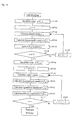
- Fig. 1 is a flow chart which shows an error correction encoding method according to a first embodiment of the present invention, and this method is implemented by using the turbo encoder 61 shown in Fig. 11 as in the aforementioned known example.
- ST41 designates a processing step for determining the block length N of the interleaver 63 at the start of transmission.
- ST42 designates a processing step for preparing an interleaver pattern of the block length N.
- ST43 designates a processing step for initializing the values of the registers 65 of the first convolutional encoder 62 and the values of the registers 66 of the second convolutional encoder 64, which will be described later.
- ST44 designates a processing step for buffering an information bit sequence u for one block.
- ST45 designates a processing step for turbo encoding and outputting parity bit sequences p a and p b by means of the turbo encoder 61.
- ST46 designates a processing step for determining whether a frame under processing is the last one and performing switching the processing operation.
- ST47 designates a processing step for performing transmission termination processing for the last or final transmission frame.
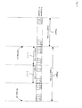
- Fig. 2 is a view illustrating a transmission frame configuration prepared by a turbo encoding method according to the first embodiment of the present invention.
- 10 designates a separator or delimiter between a first transmission frame 1 and a second transmission frame 2.
- 11 designates a transmission information bit sequence u of the first transmission frame 1.
- 12 designates a transmission parity bit sequence p a of the first transmission frame 1.
- 13 designates a transmission parity bit sequence p b of the first transmission frame 1.
- 14 designates a range representing information bits of the information bit sequence u in the second transmission frame 2 included in a decoding range 18.
- 15 designates a range representing parity bits of the parity bit sequence p a in the second transmission frame 2 included in the decoding range 18.
- 16 designates a range representing information bits of the information bit sequence u in the second transmission frame 2 included in a decoding range 19.
- 17 designates a range representing parity bits of the parity bit sequence p b in the second transmission frame 2 included in the decoding range 19.
- 18 designates a range of a reception sequence which is input to the first decoder 81 in the iterative decoding of the first transmission frame 1.
- 19 designates a range of a reception sequence which is input to the second decoder 82 in the iterative decoding of the first transmission frame 1.
- 20 designates a delimiter between the second transmission frame 2 and a third transmission frame 3.
- 21 designates a transmission information bit sequence u of the second transmission frame 2.
- 22 designates a transmission parity bit sequence p a of the second transmission frame 2.
- 23 designates a transmission parity bit sequence p b of the second transmission frame 2.
- 24 designates a range representing information bits of the information bit sequence u in the third frame 3 included in a decoding range 28.
- 25 designates a range representing parity bits of the parity bit sequence p a in the third frame 3 included in the decoding range 28.
- 26 designates a range representing information bits of the information bit sequence u in the third frame 3 included in a decoding range 29.
- 27 designates a range representing parity bits of the parity bit sequence p b in the third frame 3 included in the decoding range 29.
- 28 designates a range of a reception sequence which is input to the first decoder 81 in the iterative decoding of the second transmission frame 2.
- 29 designates a range of a reception sequence which is input to the second decoder 82 in the iterative decoding of the second transmission frame 2.
- Fig. 3 is a view illustrating a decoding method according to the first embodiment of the present invention.
- ST121 designates a processing step for determining the block length N in the interleaver at the start of reception.
- ST122 designates a processing step for preparing an interleaver pattern of the block length N.
- ST123 designates a processing step for receiving and buffering a reception sequence corresponding to a target frame which is intended to be subjected to decoding processing.
- ST124 designates a processing step for determining whether the target frame to be decoded is the last or final reception frame.
- ST125 designates a processing step for receiving and buffering a reception sequence corresponding to a frame following the target frame to be decoded.
- ST126 designates a processing step for extracting, from the reception sequence of the following frame, reception sequences which correspond to the area 14, area 15, area 16 and area 17 in Fig. 2 and which are required to be input to the iterative decoding means, and for saving them in a memory.
- ST127 designates a processing step for performing iterative decoding and outputting an estimated information bit sequence u'.
- ST128 designates a processing step for switching the operation mode of the iterative decoding means according to a transmission termination method which is carried out during transmission when the target frame to be decoded is the final reception frame.
- step ST41 the block length N of the interleaver 63 is determined in step ST41.
- step ST42 an interleaver pattern for the block length N is prepared in step ST42.
- the registers 65 of the first convolutional encoder 62 and the registers 66 of the second convolutional encoder 64 are initialized in step ST43. These initializations are carried out only at the start of transmission, but not at delimiters between the transmission frames.
- the present invention is greatly different from the known art in this respect.
- An information bit sequence u for one frame is buffered in step ST44.
- Turbo encoding of the frame is carried out to output transmission parity bits p a , p b in step ST45.
- step ST46 it is determined whether the transmission frame being now processed is the last one. When the frame being processed is not the last one, a return is performed to step ST44 where the turbo encoding processing of the following frame is carried out. When the frame being processed is the last one, the termination of the transmission is carried out in ST47.
- the initialization of the convolutional encoders is not carried out at delimiters between transmission frames. Accordingly, tail bits necessary for initialization need not be added, and hence it is possible to avoid reduction in the transmission efficiency due to the tail bits. In addition, there is no need of securing areas for tail bits in transmission frames, thus making it possible to simplify the configuration of the transmission frames.
- the first convolutional encoder 62 and the second convolutional encoder 64 do not calculate tail bits of the first transmission frame 1 but perform encoding of the frame 2 while keeping the states of the registers.
- the parity bit sequences in the area 15 and the area 17 are subjected to the constraint of the first transmission frame 1.
- the initial value ⁇ (S j, 0 ) of the forward path metric ⁇ (S j, k ) is calculated as follows.
- the first transmission frame 1 is calculated by the aforementioned expression (3).
- the forward path metric ⁇ (S j, N ) of the preceding frame at time point N is assumed to be the initial value ⁇ (S j, 0 ) of the forward path metric of the target frame to be decoded.
- the area of the information bit sequence u corresponding to the area 15 of the parity bit sequence p a is the area 14, and the area of the information bit sequence u corresponding to the area 17 of the parity bit sequence p b is the area 16.
- the area 14 corresponds to the leading or head portion of the information bit sequence u of the second transmission frame 2.
- the area 16, in which the information bit sequence u input to the second convolutional encoder 64 is interleaved is scattered in the whole area of the information bit sequence u of the second transmission frame 2.
- the iterative decoding cannot be started until all the reception sequences, which should be decoded, have been received.
- the decoding of the first transmission frame 1 is started after the whole second transmission frame 2 has been received.
- the decoding of the second transmission frame 2 is started after the whole third frame 3 has been received. Therefore, a delay for one frame is generated before the calculation of the decoding results.
- step ST121 the block length N of the interleaver is decided in step ST121.
- step ST122 an interleaver pattern for the block length N is prepared in step ST122.
- step ST123 a reception sequence corresponding to a target frame to be decoded is received and buffered.
- step ST124 it is determined whether the target frame to be decoded is the final or last reception frame. If the target frame to be decoded is not the final reception frame, a reception sequence corresponding to a frame following the target frame to be decoded is received and buffered in step ST125.
- step ST126 reception sequences z' u, a , z' p, a , z' u, b , z' p, b corresponding to the area 14, area 15, area 16 and area 17 in Fig. 2 are extracted from the reception sequences of the following frame and saved in a memory.
- step ST127 iterative decoding is carried out from a reception sequence x in which noise is mixed with the information bit sequence u, reception sequences y a and y b in which noise is mixed with parity bit sequences p a and p b , and the reception sequences z' u, a , z' p, a , z' u, b , z' p, b , to output the estimated information bit sequence u'. Thereafter, a return is performed to step ST123 where the decoding processing for the following target frame to be decoded is continued.
- step ST124 when it is determined in step ST124 that the target frame to be decoded is the final reception frame, processing of switching the operation mode of the iterative decoding means is carried out according to a method of processing transmission termination during transmission in step ST128.
- reception sequences z a, u , z b, u , z a, p , z b, p corresponding to tail bits are extracted, and they are input to the iterative decoder together with the reception sequence x corresponding to the information bit sequence u and the reception sequences y a , y b corresponding to the parity bit sequences p a , p b , and are subjected to decoding processing.
- the decoding operation is ended without performing any processing for the concerned target frame to be decoded.
- turbo symbol in which the number of input information bits is 1 and the number of output parity bits is 2, has been concretely described.
- parameters for the turbo symbol applicable to the first embodiment, including, for example, such cases as two or more input information bits, three or more parity bits, punctured parity bits, and so on.
- the initialization of the convolutional encoders is not carried out at delimiters between transmission frames, and hence there is provided an effect that tail bits necessary for initialization need not be added. Accordingly, reduction in the transmission efficiency due to the tail bits can be avoided. In addition, there is no need for securing areas for the tail bits in the transmission frames, so the configuration of the transmission frames can be made more straightforward.
- the first embodiment exerts an extremely suitable effect when applied in particular to such forms of communications as satellite communications, etc., in which transmission or reception continues for a long period of time.
- Fig. 4 shows a transmission sequence comprising an information bit sequence and a parity bit sequence serially permuted which are encoded by a turbo encoding method according to a second embodiment of the present invention.
- 141 designates a partial frame in which an information bit u k corresponding to the area 14 in the frame 2, a parity bit p b, k corresponding to the area 15 in the same frame, and a parity bit p a, k corresponding to the area 17 in the same frame are arranged in the order of (u k , p a, k , p b, k ).
- 142 designates a partial frame in which an information bit u k corresponding to the area 16 in the frame 2, a parity bit p a, k following the area 15 included in a parity bit sequence 22, and a parity bit p b, k following the area 17 included in a parity bit sequence 23 are arranged in the order of (u k , p a, k , p b, k ).
- Fig. 5 shows an error correction decoding method according to the second embodiment of the present invention.
- ST151 designates a processing step for determining the block length N of the interleaver at the start of reception.
- ST152 designates a processing step for preparing an interleaver pattern of the block length N.
- ST153 designates a processing step for receiving and buffering a target frame intended to be subjected to decoding processing.
- ST154 designates a processing step for rearranging the order of the reception sequence x included in the target frame to be decoded into the original order.
- ST155 designates a processing step for determining whether the target frame to be decoded is the final frame.
- ST156 designates a processing step for receiving and buffering reception sequences for the first 6 ⁇ T' time points of a frame following the target frame to be decoded.
- ST157 designates a processing step for extracting the reception sequences corresponding to the area 14, area 15, area 16 and area 17 in Fig. 2 from the reception sequences of the following frame buffered in the step ST156 and saving them in a memory.
- ST158 designates a processing step for performing iterative decoding and outputting an estimated information bit sequence u'.
- ST159 designates a processing step for switching the operation mode of the iterative decoding means by a method of processing transmission termination during transmission when the target frame to be decoded is the final reception frame.
- the decoding can not be done until all the reception sequences corresponding to the area 16 in the frame 2 have been received. That is, the reception sequences corresponding to the area 16 scatter over the whole frame 2, so the decoding can not be started until all the reception sequences corresponding to the frame 2 have been received.
- the second embodiment of the present invention can solve such a problem.
- the block length N of the interleaver is first determined in step ST151, as shown in Fig. 5. Then, an interleaver pattern for the block length N is prepared in step ST152. After a reception sequence corresponding to the target frame to be decoded is received in step ST153, the order of the reception sequence x corresponding to the information bit sequence is rearranged as before in step ST154.
- step ST155 When it is determined in step ST155 that the concerned target frame to be decoded is not the final reception frame, a reception sequence corresponding to the first 6xT' bits of the following frame is received and buffered in step ST156.
- step ST157 reception sequences z' u, a , z' p, a , z' u, b , z' p, b corresponding to the area 14, area 15, area 16 and area 17 in Fig. 2 necessary for calculating the backward path metric ⁇ (S j, k ) are extracted from among the buffered reception sequences and saved in a memory.
- step ST158 iterative decoding is carried out from the reception sequence x in which noise is mixed with the information bit sequence u, the reception sequence y a , y b in which noise is mixed with the parity bit sequences p a , p b , and the reception sequences z' u, a , z' p, a , z' u, b , z' p, b , thereby to output an estimated information bit sequence u'.
- a return is performed to step ST153 where the decoding processing of the following target frame to be decoded is continued.
- step ST155 when it is determined in step ST155 that the target frame to be decoded is the final reception frame, the processing of switching the operation mode of the iterative decoding means is carried out according to a method of processing transmission termination during transmission in step ST159.
- the reception sequences z a, u , z b, u , z a, p , z b, corresponding to the tail bits are extracted and input to the iterative decoders together with the reception sequence x corresponding to the information bit sequence u and the reception sequences y a , y b corresponding to the parity bit sequences p a , p b , so that decoding processing is carried out by the iterative decoder.
- the decoding operation is terminated without performing any processing to the concerned target frame to be decoded.
- the second embodiment being different from the first embodiment in which iterative decoding is started after all the reception sequences of the following frame have been received, iterative decoding is started after only parts of the areas 141 and 142 of the reception sequences of the following frame have been received.
- the second embodiment is greatly distinct in this respect from the first embodiment. All the reception sequences z' u, a , z' p, a , z' u, b , z' p, b corresponding to the area 14, area 15, area 16 and area 17 in Fig. 2 necessary for calculating the backward path metric ⁇ (S j, k ) are included in the reception sequences corresponding to the areas 141 and 142, so it becomes possible to perform the iterative decoding immediately after the step ST157 has been completed.
- turbo symbol in which the number of input information bits is one and the number of output parity bits is two
- parameters for the turbo symbol including, for example, such ones as having two or more input information bits or three or more parity bits, ones puncturing the parity bits, and so on.
- the second embodiment exerts an extremely suitable effect particularly when applied to such forms of communications as satellite communications, etc., in which transmission or reception continues for a long period of time.
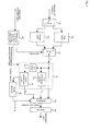
- Fig. 6 shows an encoder according to a third embodiment of the present invention.
- a turbo encoder 61 includes a first convolutional encoder 62 for convolutionally encoding an information bit sequence u thereby to output a parity bit sequence p a , an interleaver 63, and a second convolutional encoder 64 for convolutionally encoding the information bit sequence u permuted by the interleaver 63 thereby to output a parity bit sequence p b .
- a first buffer 161 buffers the transmission information bit sequence u for each transmission frame. Also, a second buffer 162 buffers the transmission information bit sequence u for each transmission frame.
- a switch 163 switches between the first and second buffers 161, 162 into which the transmission information bit sequence u is saved.
- a switch 164 switches between the first and second buffers 161, 162 from which the transmission information bit sequence u is input to the turbo encoder 61.
- a multiplexer 165 converts the transmission information bit sequence u and the transmission parity bit sequences p a , p b into a serial sequence.
- a modulator 166 modulates a transmission sequence output from the multiplexer 165 into a transmission signal.
- a transmission termination processing control means 167 controls the transmission termination processing which is performed on the last or final transmission frame at the end of transmission.
- a tail bit calculator 168 calculates tail bits.
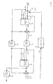
- Fig. 7 shows a decoder according to the third embodiment of the present invention.
- a demodulator 170 receives a reception signal and outputs a reception sequence.
- a first buffer 171 buffers the reception sequence from the demodulator 170 for each received frame.
- a second buffer 172 also buffers the reception sequence from the demodulator 170 for each received frame.
- a third buffer 173 also buffers the reception sequence from the demodulator 170 for each received frame.
- a switch 174 switches between the first, second and third buffers 171, 172, 173 into which the reception sequence is saved.
- a switch 175 switches between the first, second and third buffers 171, 172, 173 from which a reception sequence corresponding to a target frame to be decoded is input to an iterative decoder 179.
- a switch 176 switches between the first, second and third buffers 171, 172, 173 from which a reception sequence corresponding to a frame following the target frame to be decoded is input to the iterative decoder 179.
- a first divider 177 divides the reception sequence of the target frame to be decoded into the reception sequence x corresponding to the transmission information bit sequence u, and the reception sequences y a , y b corresponding to the transmission parity bit sequence p a , p b .
- a second divider 178 extracts and divides reception sequences z' u, a , z' p, a , z' u, b , z' p, b corresponding to the area 14, area 15, area 16 and area 17 in Fig. 2 from a reception sequence of the frame following the target frame to be decoded.
- An iterative decoder 179 receives an output of the first divider 177 and an output of the second divider 178 and outputs an estimate value u' of the transmission information bits.
- a reception termination control means 180 controls the reception termination processing which is performed on the last or final reception frame at the end of reception.
- transmission information bit sequences u are continuously sent from an information source.
- the transmission information bit sequences u are saved in the first buffer 161 or the second buffer 162 for each transmission frame.
- a destination buffer into which the transmission information bit sequences u are to be saved is switched to an empty buffer by means of the switch 163. For instance, when a first transmission information bit sequence u corresponding to a current frame to be decoded has been saved in the first buffer 161, the switch 163 is thrown to a side b to save a second transmission information bit sequence u corresponding to the following frame so that the second transmission information bit sequence u is saved in the second buffer 162.
- the switch 164 is thrown to a side a, so that a transmission information bit sequence u corresponding to a target frame to be transmitted is input to the turbo encoder 61.
- the transmission information bit sequence u and the transmission parity bit sequences p a , p b output from the turbo encoder 61 are input to the multiplexer 165 where the transmission bit sequences are converted into a serial sequence, which is then input to the modulator 166.
- the modulator 166 modulates the serial sequence into a transmission signal, which is then output therefrom.
- the switch 163 and the switch 164 are thrown to the side a and the side b, respectively, so that encoding of the following transmission frame is started and at the same time the information bit sequence u corresponding to the following transmission frame is saved in the second buffer 162.
- the registers in the first and second convolutional encoders 62 and 64 of the turbo encoder 61 are initialized at the terminal end of each encoded word, i.e., each time the transmission frame is changed from one to another.
- tail bits for initialization are output for transmission.
- such initialization is carried out only at the start of transmission, but not at delimiters between transmission frames.
- the present invention is largely different from the aforementioned known art in this respect.
- the registers in the first and second convolutional encoders 62 and 64 of the turbo encoder 61 are not initialized, but the encoding is carried out while keeping the final state of the preceding frame.
- the switch 163 and the switch 164 are thrown to the side b and the side a, respectively, so that encoding of the following transmission frame is started, and at the same time, an information bit sequence u corresponding to a further transmission frame next to the following transmission frame is saved in the second buffer 162.
- the transmission termination processing control means 167 receives a transmission termination signal notifying the termination of transmission.
- the transmission termination processing control means 167 outputs a transmission termination control signal to the turbo encoder 61.
- the turbo encoder 61 is instructed to output a register value D of the convolutional encoders.
- the tail bit calculator 168 receives the register value D and calculates tail bits based thereon, which are then output to the multiplexer 166.
- the transmission termination processing control means 167 throws the switch 164 down to a side c, so that the dummy bits are input to the turbo encoder 61.
- the reception signal is converted into a reception sequence by means of the demodulator 170, as shown in Fig. 7.
- the reception sequence is saved in the first buffer 171 or the second buffer 172 or the third buffer 173 for each received frame.
- the destination buffer into which each reception sequence is saved is switched to an empty buffer by means of the switch 174. For instance, a reception sequence corresponding to a frame to be decoded is saved in the first buffer 171, and when such saving has been completed, the switch 174 is thrown to the side b to save a reception sequence corresponding to the following frame in the second buffer 172. Then, when saving of the reception sequence corresponding to the following frame has been completed, the switch 174 is thrown to the side c so as to save a reception sequence corresponding to a frame following the following frame.
- a decoding operation is started.
- the switch 175 is thrown to the side a so that the reception sequence corresponding to the target frame to be decoded is input to the first divider 177.
- a reception sequence x corresponding to the transmission information bit sequence u and reception sequences y a , y b corresponding to the transmission parity bit sequences p a , p b are input to the iterative decoder 179.
- the switch 176 is thrown to the side b so that the reception sequence corresponding to the frame following the target frame to be decoded is input to the second divider 178.
- the second divider 178 extracts reception sequences z' u, a , z' p, a , z' u, b , z' p, b , corresponding to the area 14, area 15, area 16 and area 17 in Fig. 2, and inputs them to the iterative decoder 179.
- the iterative decoder 179 carries out the iterative decoding, and outputs an estimate value u' of the transmission information bits.
- a decoding operation is started with the received frame saved in the second buffer being made a new frame to be decoded, and the received frame saved in the third buffer being made a frame following the new frame to be decoded.
- the switch 174 is thrown to the side a so as to further save the following reception sequence.
- the switch 175 is thrown to the side b, and the switch 176 is thrown to the side c.
- the reception termination control means 180 receives a reception termination signal notifying the termination of transmission.
- the reception termination control means 180 outputs a reception termination control signal to the second divider 178 and the iterative decoder 179.
- the second divider 178 and the iterative decoder 179 operate to switch the iterative decoding operation according to a method or technique of processing transmission termination performed at the sending side.
- reception sequences z a, u , z b, u , z a, p , z b, p corresponding to the tail bits is extracted and input to the iterative decoder 179 together with the reception sequence x corresponding to the information bit sequence and the reception sequences y a , y b corresponding to the parity bit sequences, and decoding processing is carried out by the iterative decoder 179.
- the decoding operation is terminated without performing any processing to the final frame to be decoded.
- turbo symbol in which the number of input information bits is one and the number of output parity bits is two
- parameters for the turbo symbol including, for example, such ones as having two or more input information bits or three or more parity bits, ones puncturing the parity bits, and so on.
- the initialization of the convolutional encoders is not carried out at delimiters between transmission frames, and therefore there is provided an effect that tail bits necessary for initialization need not be added. Accordingly, reduction in the transmission efficiency due to the tail bits can be avoided. In addition, there is no need for securing areas for tail bits in the transmission frames, so the configuration of the transmission frames can be made more straightforward. Thus, it also possible to avoid reduction in the transmission efficiency due to the tail bits.
- the third embodiment exerts an extremely suitable effect particularly when applied to such forms of communications as satellite communications, etc., in which transmission or reception continues for a long period of time.
- Fig. 8 shows an encoder according to a fourth embodiment of the present invention.
- the same or like parts of this fourth embodiment as those of the third embodiment shown in Fig. 6 are identified by the same symbols while omitting an explanation thereof.
- a new symbol 169 designates a permuter for permuting the order of a transmission information bit sequence u in such a manner that a certain number of bits in the sequence u, which are input to the second convolutional encoder 64 at early points in time, follow a certain number of bits in the sequence u, which are input to the first convolutional encoder 62 at early points in time.
- Fig. 9 shows a decoder according to the fourth embodiment of the present invention.
- the same or like parts of this fourth embodiment as those of the third embodiment shown in Fig. 7 are identified by the same symbols while omitting an explanation thereof.
- a new symbol 181 designates an inverse permuter for rearranging the order of a reception sequence x to its original order.
- the decoding can not be done until all the reception sequences corresponding to the area 16 in a frame 2 have been received. That is, the reception sequences corresponding to the area 16 scatter over the whole frame 2, so the decoding can not be started until all the reception sequences corresponding to the frame 2 have been received.
- the fourth embodiment is intended to solve this problem.
- the reception signal is converted into a reception sequence by means of the demodulator 170, as shown in Fig. 9.
- the reception sequence is saved in the first buffer 171 or in the second buffer 172 for each received frame.
- the destination buffer into which each reception sequence is saved is switched to an empty buffer by means of the switch 174. For instance, a reception sequence corresponding to a target frame to be decoded is saved in the first buffer 171, and when such saving has been completed, the switch 174 is switched over in such a manner that it is thrown to the side b to save a reception sequence corresponding to the following frame in the second buffer 172.
- the switch 175 is thrown to the side a, so that the reception sequence corresponding to the target frame to be decoded is input to the first divider 177. Then, the first divider 177 outputs a reception sequence x corresponding to the transmission information bit sequence u and reception sequences y a , y b corresponding to the transmission parity bit sequences p a , p b .
- the inverse permuter 181 rearranges the order of the reception sequence x into its original order.
- the reception sequence x and the reception sequences y a , y b thus rearranged are input to the iterative decoder 179.
- the switch 176 is thrown to the side b so that a reception sequence (only part thereof is saved) corresponding to a frame following the target frame to be decoded is input to the second divider 178.
- the second divider 178 extracts reception sequences z' u, a , z' p, a , z' u, b , z' p, b , corresponding to the area 14, area 15, area 16 and area 17 in Fig. 2, and inputs them to the iterative decoder 179.
- the iterative decoder 179 carries out the iterative decoding, and outputs an estimate value u' of the transmission information bits.
- a decoding operation is started with the following frame being made a new target frame to be decoded.
- the remainders other than those already received among the reception sequences corresponding to the new target frame to be decoded are saved in the second buffer.
- reception sequences of the first 6*T' time points corresponding to the areas 141 and 142 are saved in the first buffer.
- a decoding operation is started with the received frame saved in the second buffer being made a new frame to be decoded, and the received frame saved in the first buffer being made a frame following the new frame to be decoded.
- the switch 174 is thrown to the side a, so that the remaining reception sequences of the frame following the new frame are saved. Also, the switch 175 is thrown to the side b, and the switch 176 is thrown to the side a.
- reception frames are continuously received, the above operation is continuously carried out in this manner.
- the iterative decoding is started after only parts of areas 141 and 142 of the reception sequence of the following frame have been received.
- the fourth embodiment is greatly different in this respect from the third embodiment.
- reception sequences z' u, a , z' p, a , z' u, b , z' p, b corresponding to the area 14, area 15, area 16 and area 17 necessary for calculating the backward path metric ⁇ (S j, k ) are included in the reception sequences corresponding to the areas 141 and 142, so that iterative decoding can be carried out immediately after reception sequences of the first 6XT' time points corresponding to the areas 141 and 142 have been received and saved in the buffers.
- turbo symbol in which the number of input information bits is one and the number of output parity bits is two
- parameters for the turbo symbol including, for example, such ones as having two or more input information bits, or three or more parity bits, ones puncturing the parity bits, and so on.
- the fourth embodiment achieves an extremely suitable effect particularly when applied to such forms of communications as satellite communications, etc., in which transmission or reception continues for a long period of time.
- the initialization of the convolutional encoders is not performed at delimiters between transmission frames, and hence tail bits necessary for initialization need not be added, thus making it possible to avoid reduction in the transmission efficiency due to the tail bits.
Landscapes
- Physics & Mathematics (AREA)
- Probability & Statistics with Applications (AREA)
- Engineering & Computer Science (AREA)
- Theoretical Computer Science (AREA)
- Error Detection And Correction (AREA)
- Detection And Correction Of Errors (AREA)
Abstract
Description






Claims (10)
- An error correction encoding method comprising:a turbo encoding step (ST45) in which a transmission information bit sequence is divided into a plurality of frames, and registers (65, 66) in each recursive systematic convolutional encoder (62, 64) are initialized before turbo encoding of a first frame, and after turbo encoding of the first frame is carried out, a second frame and following frames are continuously subjected to turbo encoding without initializing the registers (65, 66) in each recursive systematic convolutional encoder (62, 64) before the turbo encoding of the second frame and the following frames; anda transmission termination processing step (ST47) in which tail bits for initializing the registers (65, 66) in each recursive systematic convolutional encoder (62, 64) are calculated only after a final frame has been subjected to turbo encoding.
- The error correction encoding method according to claim 1, wherein in the transmission termination processing step (ST47), known pre-determined dummy bits which are not an information bit sequence to be transmitted are inserted into a final transmission frame from a certain time point to a final time point thereof.
- The error correction encoding method according to claim 1 or 2, wherein each of the divided frames is permuted in such a manner that a certain number of bits, among the transmission information bit sequence, which are input to a second one (64) of the recursive systematic convolutional encoders at early time points follow a certain number of bits which are input to a first one (62) of the recursive systematic convolutional encoders at early time points.
- An error correction decoding method comprising:a buffering processing step (ST123, ST125) in which a transmission information bit sequence is divided into a plurality of frames, and when a reception sequence is decoded in which noise is mixed with the transmission information bit sequence which has been subjected to turbo encoding without initializing registers (65, 66) in each recursive systematic convolutional encoder (62, 64) of a turbo encoder (61) at a delimiter of each transmission frame, a reception sequence corresponding to a target frame to be decoded is buffered and at the same time a reception sequence corresponding to a frame following the target frame to be decoded is also buffered;an extraction processing step (ST126) in which only reception sequences needed to be input to iterative decoding means (179) are extracted from reception sequences of the following frame;a decoding processing step (ST127) in which an estimate value of a transmission information bit sequence corresponding to the target frame to be decoded is calculated by the iterative decoding means (179);a final frame determination processing step (ST124) in which it is determined whether the target frame to be decoded is a final reception frame;an operation mode switching processing step (ST128) in which when the target frame to be decoded is a final reception frame, an operation procedure of the iterative decoding means (179) is switched for the final reception frame; anda final frame decoding processing step (ST127) in which an estimate value of the transmission information bit sequence corresponding to the target frame to be decoded is calculated by the iterative decoding means (179) corresponding to the switched mode.
- The error correction decoding method according to claim 4, wherein in the final frame decoding processing step (ST127), a reception sequence is decoded in which noise is mixed with a transmission bit sequence into which known pre-determined dummy bits, which are not an information bit sequence to be transmitted, are inserted from a certain time point to a final time point of a final transmission frame.
- The error correction decoding method according to claim 4 or 5,
wherein in the buffering processing step (ST123, ST125), when a reception sequence is decoded in which noise is mixed with a sequence whose order is permuted in such a manner that a certain number of bits, among the transmission information bit sequence, which are input to a second one (64) of the recursive systematic convolutional encoders at early time points follow a certain number of bits which are input to a first one (62) of the recursive systematic convolutional encoders at early time points, a reception sequence corresponding to the transmission information bit sequence is rearranged into its original order after a reception sequence corresponding to the target frame to be encoded is buffered. - An error correcting encoding apparatus comprising:wherein transmission frames are continuously encoded without initializing registers (65, 66) in recursive systematic convolutional encoders (62, 64) of the turbo encoder (61) at a terminal end of each transmission frame, and without calculating tail bits.buffers (161, 162) for saving a transmission information bit sequence for each transmission frame;a first switch (163) for switching between the buffers (161, 162) into which the transmission information bit sequence is saved;a second switch (164) for switching between the buffers (161, 162) from which the transmission information bit sequence is input to a turbo encoder (61);a multiplexer (165) for multiplexing the transmission information bit sequence and transmission parity bit sequences;transmission termination processing control means (167) for performing control in such a manner that only a final transmission frame is subjected to transmission termination processing; anda tail bit calculator (168) for calculating tail bits;
- The error correction encoding apparatus according to claim 7, further comprising a permuter (169) for permuting the order of the transmission information bit sequence in such a manner that a certain number of bits, among the transmission information bit sequence, which are input to a second one (64) of the recursive systematic convolutional encoders at early time points follow a certain number of bits which are input to a first one (62) of the recursive systematic convolutional encoders at early time points.
- An error correction decoding apparatus comprising:wherein the transmission information bit sequence is divided into a plurality of frames, and a reception sequence is decoded in which noise is mixed with a transmission bit sequence which has been subjected to turbo encoding without initializing registers (65, 66) in each recursive systematic convolutional encoder (62, 64) of a turbo encoder (61) at a delimiter of each transmission frame.buffers (171, 172, 173) for saving a reception sequence for each reception frame;a first switch (174) for switching between the buffers (171, 172, 173) into which the reception sequence is saved;a second switch (175) for switching between the buffers (171, 172, 173) from which a reception sequence corresponding to a target frame to be decoded is retrieved;a third switch (176) for switching between the buffers (171, 172, 173) from which a reception sequence corresponding to a frame following the target frame to be decoded is retrieved;a first divider (177) for dividing the reception sequence corresponding to the frame to be decoded and inputting the reception sequence thus divided to an iterative decoder (179);a second divider (178) for extracting and dividing only necessary ones from among reception sequences corresponding to a frame following the target frame to be decoded and inputting the necessary ones thus extracted and divided to the iterative decoder (179); andreception termination processing control means (180) for performing control in such a manner that only a final reception frame is subjected to reception termination processing;
- The error correction decoding apparatus according to claim 9, further comprising an inverse permuter (181) for rearranging a reception sequence corresponding to the transmission information bit sequence into its original order,
wherein a reception sequence is decoded in which noise is mixed with a sequence whose order is permuted in such a manner that a certain number of bits, among the transmission information bit sequence, which are input to a second one (64) of the recursive systematic convolutional encoders at early time points follow a certain number of bits which are input to a first one (62) of the recursive systematic convolutional encoders at early time points.
Applications Claiming Priority (2)
| Application Number | Priority Date | Filing Date | Title |
|---|---|---|---|
| JP2001105959A JP4451008B2 (en) | 2001-04-04 | 2001-04-04 | Error correction encoding method and decoding method and apparatus |
| JP2001105959 | 2001-04-04 |
Publications (2)
| Publication Number | Publication Date |
|---|---|
| EP1248377A2 true EP1248377A2 (en) | 2002-10-09 |
| EP1248377A3 EP1248377A3 (en) | 2003-12-17 |
Family
ID=18958556
Family Applications (1)
| Application Number | Title | Priority Date | Filing Date |
|---|---|---|---|
| EP02006348A Withdrawn EP1248377A3 (en) | 2001-04-04 | 2002-03-21 | Error correction encoding method and apparatus, and error correction decoding method and apparatus |
Country Status (4)
| Country | Link |
|---|---|
| US (1) | US6912684B2 (en) |
| EP (1) | EP1248377A3 (en) |
| JP (1) | JP4451008B2 (en) |
| CN (1) | CN1208906C (en) |
Cited By (2)
| Publication number | Priority date | Publication date | Assignee | Title |
|---|---|---|---|---|
| WO2007055467A3 (en) * | 2005-09-05 | 2009-05-07 | Lg Electronics Inc | Method and apparatus for turbo encoding and decoding |
| CN110352573A (en) * | 2017-08-07 | 2019-10-18 | 联发科技股份有限公司 | Channel bit interleaver designs for Polarization Coding chain |
Families Citing this family (15)
| Publication number | Priority date | Publication date | Assignee | Title |
|---|---|---|---|---|
| JP3931100B2 (en) * | 2002-03-12 | 2007-06-13 | 株式会社日立コミュニケーションテクノロジー | Turbo decoder and radio base station including turbo encoder, turbo encoder and decoder |
| US7254192B2 (en) * | 2002-07-12 | 2007-08-07 | Texas Instruments Incorporated | Iterative detection in MIMO systems |
| US7251770B2 (en) * | 2004-06-28 | 2007-07-31 | Telefonaktiebolaget Lm Ericsson (Publ) | Method and apparatus for decoding of turbo encoded data in a communication system |
| US7760880B2 (en) * | 2004-10-13 | 2010-07-20 | Viasat, Inc. | Decoder architecture system and method |
| US7577892B1 (en) * | 2005-08-25 | 2009-08-18 | Marvell International Ltd | High speed iterative decoder |
| JP4878958B2 (en) * | 2006-08-22 | 2012-02-15 | 株式会社エヌ・ティ・ティ・ドコモ | Wireless communication apparatus and wireless communication method |
| US7957484B2 (en) * | 2006-12-08 | 2011-06-07 | Texas Instruments Incorporated | Candidate list generation and interference cancellation framework for MIMO detection |
| US7853858B2 (en) * | 2006-12-28 | 2010-12-14 | Intel Corporation | Efficient CTC encoders and methods |
| KR100833604B1 (en) | 2007-01-09 | 2008-05-30 | 삼성전자주식회사 | Parity error detection circuit |
| US8306139B2 (en) * | 2007-01-30 | 2012-11-06 | Texas Instruments Incorporated | Systems and methods for low-complexity MIMO detection using leaf-node prediction via look-up tables |
| US8155217B2 (en) * | 2007-01-30 | 2012-04-10 | Texas Instruments Incorporated | Systems and methods for low-complexity MIMO detection with analytical leaf-node prediction |
| WO2009119057A1 (en) * | 2008-03-24 | 2009-10-01 | パナソニック株式会社 | Wireless communication device and error correction encoding method |
| JP5721316B2 (en) * | 2009-03-03 | 2015-05-20 | シャープ株式会社 | Transmitting apparatus, receiving apparatus, and communication system |
| TWI557747B (en) * | 2015-02-13 | 2016-11-11 | 瑞昱半導體股份有限公司 | Memory control module and method thereof and error correcting code encode/decode circuit and method thereof |
| JP2019041182A (en) * | 2017-08-23 | 2019-03-14 | 株式会社東芝 | Radio communication equipment and radio communication method |
Family Cites Families (7)
| Publication number | Priority date | Publication date | Assignee | Title |
|---|---|---|---|---|
| FR2675971B1 (en) * | 1991-04-23 | 1993-08-06 | France Telecom | CORRECTIVE ERROR CODING METHOD WITH AT LEAST TWO SYSTEMIC CONVOLUTIVE CODES IN PARALLEL, ITERATIVE DECODING METHOD, CORRESPONDING DECODING MODULE AND DECODER. |
| US5721745A (en) * | 1996-04-19 | 1998-02-24 | General Electric Company | Parallel concatenated tail-biting convolutional code and decoder therefor |
| US6772391B1 (en) * | 1998-10-13 | 2004-08-03 | Interdigital Technology Corporation | Hybrid interleaver for turbo codes |
| US6028897A (en) * | 1998-10-22 | 2000-02-22 | The Aerospace Corporation | Error-floor mitigating turbo code communication method |
| FI106758B (en) * | 1999-04-16 | 2001-03-30 | Nokia Networks Oy | Segmentation mechanism for a block encoder |
| US6484285B1 (en) * | 2000-02-07 | 2002-11-19 | Ericsson, Inc. | Tailbiting decoder and method |
| JP2001313571A (en) | 2000-05-01 | 2001-11-09 | Mitsubishi Electric Corp | Demodulation method and demodulation device |
-
2001
- 2001-04-04 JP JP2001105959A patent/JP4451008B2/en not_active Expired - Fee Related
-
2002
- 2002-03-15 US US10/097,347 patent/US6912684B2/en not_active Expired - Fee Related
- 2002-03-21 EP EP02006348A patent/EP1248377A3/en not_active Withdrawn
- 2002-04-03 CN CN02106019.3A patent/CN1208906C/en not_active Expired - Fee Related
Cited By (4)
| Publication number | Priority date | Publication date | Assignee | Title |
|---|---|---|---|---|
| WO2007055467A3 (en) * | 2005-09-05 | 2009-05-07 | Lg Electronics Inc | Method and apparatus for turbo encoding and decoding |
| US8166373B2 (en) | 2005-09-05 | 2012-04-24 | Lg Electronics Inc. | Method and apparatus for turbo encoding and decoding |
| CN110352573A (en) * | 2017-08-07 | 2019-10-18 | 联发科技股份有限公司 | Channel bit interleaver designs for Polarization Coding chain |
| CN110352573B (en) * | 2017-08-07 | 2022-04-05 | 联发科技股份有限公司 | Method of interleaving encoded bits, wireless device, and computer readable medium thereof |
Also Published As
| Publication number | Publication date |
|---|---|
| US6912684B2 (en) | 2005-06-28 |
| JP4451008B2 (en) | 2010-04-14 |
| CN1379549A (en) | 2002-11-13 |
| EP1248377A3 (en) | 2003-12-17 |
| CN1208906C (en) | 2005-06-29 |
| US20020184595A1 (en) | 2002-12-05 |
| JP2002305454A (en) | 2002-10-18 |
Similar Documents
| Publication | Publication Date | Title |
|---|---|---|
| EP1248377A2 (en) | Error correction encoding method and apparatus, and error correction decoding method and apparatus | |
| CA2273608C (en) | Reduced-complexity max-log app decoders and related turbo decoders | |
| Anderson et al. | Tailbiting MAP decoders | |
| JP4282192B2 (en) | Iterative turbo code decoding apparatus and method for optimizing the performance of the apparatus | |
| US5208816A (en) | Generalized viterbi decoding algorithms | |
| EP1166451B1 (en) | Highly parallel map decoder | |
| US6961889B2 (en) | Encoding method having improved interleaving | |
| EP1434356B1 (en) | Turbo encoding with dummy bit insertion | |
| EP0413505B1 (en) | Generalized viterbi decoding algorithms | |
| EP0927464B1 (en) | Convolutional decoding with the ending state decided by crc bits selectively placed inside multiple coding bursts | |
| US8122327B2 (en) | Symbol-level soft output viterbi algorithm (SOVA) and a simplification on SOVA | |
| JP2002529953A (en) | Efficient interleave decoding | |
| US6812873B1 (en) | Method for decoding data coded with an entropic code, corresponding decoding device and transmission system | |
| EP1471677A1 (en) | Method of blindly detecting a transport format of an incident convolutional encoded signal, and corresponding convolutional code decoder | |
| JP2000512090A (en) | Data signal decoding method using fixed-length decision window | |
| Antonini et al. | Suppressing error floors in SCPPM via an efficient CRC-aided list viterbi decoding algorithm | |
| JP4420925B2 (en) | Method and encoder for encoding an information bit sequence | |
| US7120851B2 (en) | Recursive decoder for switching between normalized and non-normalized probability estimates | |
| JP2001352256A (en) | Decoding device and decoding method | |
| US7143334B2 (en) | Method for decoding data sequence encoded with aid of binary convolution code | |
| EP1587218A1 (en) | Data receiving method and apparatus | |
| JP2001177417A (en) | Decoder combining channel decoding and entropy decoding | |
| JP2008136006A (en) | Error correction decoder, and error correction decoding method and program used therefor | |
| WO2000057560A2 (en) | Improved turbo decoder 1 | |
| EP1347580A2 (en) | Hybrid interleaver for turbo codes |
Legal Events
| Date | Code | Title | Description |
|---|---|---|---|
| PUAI | Public reference made under article 153(3) epc to a published international application that has entered the european phase |
Free format text: ORIGINAL CODE: 0009012 |
|
| AK | Designated contracting states |
Kind code of ref document: A2 Designated state(s): AT BE CH CY DE DK ES FI FR GB GR IE IT LI LU MC NL PT SE TR |
|
| AX | Request for extension of the european patent |
Free format text: AL;LT;LV;MK;RO;SI |
|
| PUAL | Search report despatched |
Free format text: ORIGINAL CODE: 0009013 |
|
| AK | Designated contracting states |
Kind code of ref document: A3 Designated state(s): AT BE CH CY DE DK ES FI FR GB GR IE IT LI LU MC NL PT SE TR |
|
| AX | Request for extension of the european patent |
Extension state: AL LT LV MK RO SI |
|
| AKX | Designation fees paid | ||
| REG | Reference to a national code |
Ref country code: DE Ref legal event code: 8566 |
|
| STAA | Information on the status of an ep patent application or granted ep patent |
Free format text: STATUS: THE APPLICATION IS DEEMED TO BE WITHDRAWN |
|
| 18D | Application deemed to be withdrawn |
Effective date: 20040618 |