EP1248344A2 - Bipolar reactance circuit for nonlinear loads - Google Patents
Bipolar reactance circuit for nonlinear loads Download PDFInfo
- Publication number
- EP1248344A2 EP1248344A2 EP02007520A EP02007520A EP1248344A2 EP 1248344 A2 EP1248344 A2 EP 1248344A2 EP 02007520 A EP02007520 A EP 02007520A EP 02007520 A EP02007520 A EP 02007520A EP 1248344 A2 EP1248344 A2 EP 1248344A2
- Authority
- EP
- European Patent Office
- Prior art keywords
- phase
- circuit arrangement
- choke
- arrangement according
- rectifier
- Prior art date
- Legal status (The legal status is an assumption and is not a legal conclusion. Google has not performed a legal analysis and makes no representation as to the accuracy of the status listed.)
- Granted
Links
Images


Classifications
-
- H—ELECTRICITY
- H02—GENERATION; CONVERSION OR DISTRIBUTION OF ELECTRIC POWER
- H02M—APPARATUS FOR CONVERSION BETWEEN AC AND AC, BETWEEN AC AND DC, OR BETWEEN DC AND DC, AND FOR USE WITH MAINS OR SIMILAR POWER SUPPLY SYSTEMS; CONVERSION OF DC OR AC INPUT POWER INTO SURGE OUTPUT POWER; CONTROL OR REGULATION THEREOF
- H02M1/00—Details of apparatus for conversion
- H02M1/12—Arrangements for reducing harmonics from ac input or output
- H02M1/126—Arrangements for reducing harmonics from ac input or output using passive filters
Definitions
- the invention relates to a circuit arrangement for harmonic compensation for multi-phase supply networks with sinusoidal mains voltage according to the preamble of claim 1.
- Nonlinear consumers draw from a supply network with sinusoidal Supply voltages or currents are non-sinusoidal consumer voltages or currents. These deviations of the current from the sinusoidal shape result in Supply networks for distortion of the mains voltage. The distortions of the Mains voltage cause additional losses and malfunctions in others Consumers who are operated on this supply network.
- a high proportion of non-linear consumers in the supply networks three-phase rectifier and inverter circuits.
- the most common Rectifier circuit used is the uncontrolled rectifier in B6 circuit.
- Network perturbations are: increasing the Power loss in the supply network and among other consumers; brownouts and commutation drops; Deformation of the mains voltage; resonance in the web; Disturbances in neighboring assemblies and consumers, possibly through the aforementioned resonance phenomena.
- Non-linear consumers include e.g. Chokes, transformers and Power electronic assemblies, such as rectifiers, inverters, three-phase controllers etc.
- Chokes transformers
- Power electronic assemblies such as rectifiers, inverters, three-phase controllers etc.
- the increased use and the ever greater performance of power electronics Modules have led to standards being drawn up were or are in preparation, which the permissible current harmonics in specify in relation to certain supply networks, with the aim of network perturbations to limit.
- To the network-side measures count e.g. Suction throttle circuits and active harmonic compensation.
- the device-technical measures include increasing the number of pulses known from rectifier and inverter circuits (12-pulse rectifier circuits).
- the invention has for its object an improved harmonic compensation to make available, which with a simple structure the increased Use of power electronics modules with a corresponding takes into account high dynamics and also harmonics with such a high dynamic effectively compensated.
- each phase is type with a first inductance connected, each first inductor with its own phase opposite end is in turn connected to a first capacitance, all first capacitors at their respective ends facing away from the inductors are interconnected.
- the circuit is characterized by a particularly simple structure, which makes them simple and easy adapt to different network frequencies, such as 50 Hz or 60 Hz and can be dimensioned in the voltage range from low voltage to medium voltage leaves.
- the first inductors have two inductors connected in series, with between the two Choke coils each phase, a second capacitance is connected, wherein the respective ends of the second capacitances facing away from the choke coils are interconnected.
- a choke coil is looped in front of the consumer in each phase, the first inductors between the inductor and the consumer is connected to the respective phase.
- the consumer is for example a controlled or uncontrolled inverter or a controlled one or uncontrolled single-phase rectifiers, especially a B2 rectifier, a controlled or uncontrolled three-phase rectifier, in particular an M6, M3 or B6 rectifier, a controlled or uncontrolled one higher-phase rectifier, in particular an M12, M18, B12 rectifier, or an inverter.
- the choke coils are preferably of an n-phase Iron core choke combined with E-I core cut, where n is the number of phases equivalent.
- first inductors as at least one n-phase iron core choke with E-I core cut are formed, where n corresponds to the number of phases.
- Circuit arrangement 10 for a non-linear consumer 12 on a supply network 14 with three phases 16, 18, 20 and a neutral conductor 22 comprises a first inductance 24 and a first capacitance for each phase 16, 18, 20 26.
- the first inductor 24 comprises a first one for each phase 16, 18, 20 Choke coil 28 and a second choke coil 30.
- the choke coils 28, 30 and the first capacitance 26 are connected in series.
- the respective first choke coil 28 is connected to the respective phase 16, 18, 20, the respective second choke coil 30 is on one side with the respective first choke coil 28 and on the other side connected to the respective first capacitance 26.
- the first capacities 26 are facing away from the respective second choke coils Ends connected together at point 32.
- a second capacitance 34 is connected between the first and second choke coils 28, 30.
- the second capacitances 34 are also connected to one another at their respective ends facing away from the choke coils 28, 30 at a point 36.
- the mains current I 0 flows from the supply network and the consumer current I V flows to the consumer.
- This circuit arrangement 10 causes the currents I V of the nonlinear consumer 12 which are subject to harmonics to be added and subtracted from each phase a compensation current or reactance two-pole current I 1 . This leads to the fact that the currents I V taken from the supply network 14 only have a small harmonic component.
- Fig. 1 is exemplary as a non-linear consumer an uncontrolled B6 rectifier circuit with a nominal phase current of 35A is provided, and the circuit arrangement 10 according to the invention accordingly dimensioned.
- the circuit arrangement 10 according to the invention comprises a reactance dipole, which consists of three inductors 28, 30, 38 per phase 16, 18, 20 and two capacities 30, 34. It follows that the function of the reactance has 6 poles and zeros depending on the frequency and that the reactance takes positive and negative values, which means an energy consumption and corresponds to an energy output.
- the capacitance values of the first and second capacitances 26, 34 and the inductance values of the first, second and third choke coils 28, 30, 38 are dimensioned such that the zeros and poles of the function of the reactance are matched to the respective harmonic spectrum of the consumer current I V.
- the inductors 28, 30, 38 are, for example, as three-phase iron core chokes trained with E-I core cut. This alternative represents a constructive and Cost-optimized embodiment for a three-phase throttle system. However, it is also possible to use more complex embodiments for the inductors 28, 30, 38 to use, such as three single-phase chokes instead a three-phase choke with E-I core cut, provided space and costs allow this.
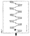
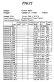
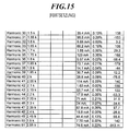
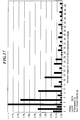
- FIGS. 6 to 17 represent harmonic spectra the uncontrolled B6 rectifier circuit with the inventive Circuit arrangement (Fig. 12 to 17) and for comparison without the circuit arrangement (Fig. 6 to 11).
- Figs. 6 to 8 and 12 to 14 comparative part load conditions.
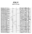
- FIG. 9 illustrates to 11 and 15 to 17 full load conditions. It is immediately obvious that the harmonic component through the use of the circuit arrangement according to the invention 10 is significantly reduced. The reduction of harmonics is surprising for device-side compensation with only passive components clear and strong.
- the rectifiers and inverters mentioned at the beginning are, for example in frequency converters, UPS systems, battery chargers, power supplies, DC power supplies, Power converters, DC drives, servo drives u.v.m. used.
Abstract
Description
Die Erfindung betrifft eine Schaltungsanordnung zur Oberschwingungskompensation für mehrphasige Versorgungsnetze mit sinusförmiger Netzspannung gemäß dem Oberbegriff des Anspruchs 1.The invention relates to a circuit arrangement for harmonic compensation for multi-phase supply networks with sinusoidal mains voltage according to the preamble of claim 1.
Nichtlineare Verbraucher beziehen aus einem Versorgungsnetz mit sinusförmigen Versorgungsspannungen bzw. -strömen nichtsinusförmige Verbraucherspannungen bzw. -ströme. Diese Abweichungen des Stromes von der Sinusform führen in Versorgungsnetzen zu Verzerrungen der Netzspannung. Die Verzerrungen der Netzspannung verursachen zusätzliche Verluste und Funktionsstörungen bei anderen Verbrauchern, die an diesem Versorgungsnetz betrieben werden. Einen hohen Anteil an nichtlinearen Verbrauchern in den Versorgungsnetzen stellen dreiphasige Gleichrichter- und Wechselrichterschaltungen dar. Die am häufigsten eingesetzte Gleichrichterschaltung ist der ungesteuerte Gleichrichter in B6-Schaltung.Nonlinear consumers draw from a supply network with sinusoidal Supply voltages or currents are non-sinusoidal consumer voltages or currents. These deviations of the current from the sinusoidal shape result in Supply networks for distortion of the mains voltage. The distortions of the Mains voltage cause additional losses and malfunctions in others Consumers who are operated on this supply network. a high proportion of non-linear consumers in the supply networks three-phase rectifier and inverter circuits. The most common Rectifier circuit used is the uncontrolled rectifier in B6 circuit.
Die nicht sinusförmigen Spannungen bzw. Ströme können mittels Fourier-Reihen
in sinusförmige Größen zerlegt werden, die aus einer Grundschwingung, wie z.B.
f = 50 Hz, und Oberschwingungen der Frequenz n·f bestehen. Ein Bewertungskriterium
für die Abweichungen einer verzerrten Stromform von der Sinusform stellt
der "THD" dar. Der Wert THD (Total Harmonic Distortion) beschreibt ein Gesamt-Oberschwingungsverhältnis
v und ist definiert als

- ist, mit
- Un = Effektivwert jeder Oberschwingung n und
U1 = Effeltivwert der Grundschwingung.
- is with
- U n = effective value of each harmonic n and
U 1 = effective value of the fundamental vibration.
Die durch die Stromoberschwingungen der Verbraucherspannung bzw. des Verbraucherstroms verursachten Auswirkungen auf das speisende Netz werden als Netzrückwirkungen bezeichnet. Typische Netzrückwirkungen sind: Erhöhung der Verlustleistung im Versorgungsnetz und bei anderen Verbrauchern; Spannungsabfälle und Kommutierungseinbrüche; Verformung der Netzspannung; Resonanzerscheinungen im Netz; Störungen bei benachbarten Baugruppen und Verbrauchern, ggf. durch die vorgenannten Resonanzerscheinungen.The by the current harmonics of the consumer voltage or the consumer current effects on the supply network are considered Network perturbations. Typical network perturbations are: increasing the Power loss in the supply network and among other consumers; brownouts and commutation drops; Deformation of the mains voltage; resonance in the web; Disturbances in neighboring assemblies and consumers, possibly through the aforementioned resonance phenomena.
Zu den nichtlinearen Verbrauchern zählen z.B. Drosseln, Transformatoren und leistungselektronische Baugruppen, wie Gleichrichter, Wechselrichter, Drehstromsteller usw. Der vermehrte Einsatz und die immer größeren Leistungen von leistungselektronischen Baugruppen haben dazu geführt, daß Normen erarbeitet wurden oder in Vorbereitung sind, die die zulässigen Stromoberschwingungen in bezug auf bestimmte Versorgungsnetze spezifizieren, mit dem Ziel, die Netzrückwirkungen zu begrenzen.Non-linear consumers include e.g. Chokes, transformers and Power electronic assemblies, such as rectifiers, inverters, three-phase controllers etc. The increased use and the ever greater performance of power electronics Modules have led to standards being drawn up were or are in preparation, which the permissible current harmonics in specify in relation to certain supply networks, with the aim of network perturbations to limit.
Bei der Reduzierung von Stromoberschwingungen unterscheidet man prinzipiell netzseitige und gerätetechnische Maßnahmen. Zu den netzseitigen Maßnahmen zählen z.B. Saugdrosselkreise und aktive Oberschwingungskompensation. Bei den gerätetechnischen Maßnahmen ist beispielsweise die Erhöhung der Pulszahl von Gleich- und Wechselrichterschaltungen bekannt (12-pulsige Gleichrichterschaltungen). A basic distinction is made when reducing current harmonics network-side and device-related measures. To the network-side measures count e.g. Suction throttle circuits and active harmonic compensation. at The device-technical measures include increasing the number of pulses known from rectifier and inverter circuits (12-pulse rectifier circuits).
Der Erfindung liegt die Aufgabe zugrunde, eine verbesserte Oberschwingungskompensation zur Verfügung zu stellen, welche bei einfachem Aufbau dem vermehrten Einsatz von leistungselektronischen Baugruppen mit einer entsprechend hohen Dynamik Rechnung trägt und auch Oberschwingungen mit einer derartig hohen Dynamik wirkungsvoll kompensiert.The invention has for its object an improved harmonic compensation to make available, which with a simple structure the increased Use of power electronics modules with a corresponding takes into account high dynamics and also harmonics with such a high dynamic effectively compensated.
Diese Aufgabe wird durch eine Schaltungsanordnung der o.g. Art mit den in Anspruch 1 gekennzeichneten Merkmalen gelöst. Vorteilhafte Ausgestaltungen der Erfindung sind in den abhängigen Ansprüchen angegeben.This task is accomplished by a circuit arrangement of the above. Kind with the claim 1 marked features solved. Advantageous embodiments of the Invention are specified in the dependent claims.
Bei der Schaltungsanordnung der o.g. Art ist jede Phase mit einer ersten Induktivität verbunden, wobei jede erste Induktivität mit ihrem von der jeweiligen Phase abgewandten Ende wiederum mit einer ersten Kapazität verbunden ist, wobei alle ersten Kapazitäten an ihren jeweiligen von den Induktivitäten abgewandten Enden miteinander verbunden sind.In the circuit arrangement of the above Each phase is type with a first inductance connected, each first inductor with its own phase opposite end is in turn connected to a first capacitance, all first capacitors at their respective ends facing away from the inductors are interconnected.
Dies hat den Vorteil, daß sich in Abhängigkeit von Verzerrungen des Verbraucherstroms, welche von dem nichtlinearen Verbraucher erzeugt werden, Reaktanzzweipolströme über die ersten Induktivitäten und Kapazitäten ergeben, welche bei entsprechender Dimensionierung der Induktivitäten und Kapazitäten die Verzerrungen bzw. Oberschwingungen kompensieren. Die Schaltung zeichnet sich durch einen besonders einfachen Aufbau aus, wodurch sie sich einfach und problemlos an verschiedene Netzfrequenzen, wie beispielsweise 50 Hz oder 60 Hz, anpassen läßt und sich im Spannungsbereich von Kleinspannung bis Mittelspannung dimensionieren läßt.This has the advantage that, depending on the distortion of the consumer current, which are generated by the nonlinear consumer, reactance two-pole currents about the first inductors and capacities, which at appropriate dimensioning of the inductors and capacitors the distortions or to compensate for harmonics. The circuit is characterized by a particularly simple structure, which makes them simple and easy adapt to different network frequencies, such as 50 Hz or 60 Hz and can be dimensioned in the voltage range from low voltage to medium voltage leaves.
In einer besonders bevorzugten Ausführungsform weisen die ersten Induktivitäten jeweils zwei in Reihe geschaltete Drosselspulen auf, wobei zwischen den beiden Drosselspulen jeder Phase jeweils eine zweite Kapazität angeschlossen ist, wobei die jeweiligen von den Drosselspulen abgewandten Enden der zweiten Kapazitäten miteinander verbunden sind. Zur Kostenminimierung sind je n Drosselspulen verschiedener Phasen zu einer n-phasigen Eisenkerndrossel mit E-I-Kernschnitt zusammengefaßt, wobei n der Zahl der Phasen entspricht. In a particularly preferred embodiment, the first inductors have two inductors connected in series, with between the two Choke coils each phase, a second capacitance is connected, wherein the respective ends of the second capacitances facing away from the choke coils are interconnected. To minimize costs, there are n choke coils different phases to an n-phase iron core choke with E-I core cut summarized, where n corresponds to the number of phases.
Beispielsweise ist in jeder Phase eine Drosselspule vor dem Verbraucher eingeschleift, wobei die ersten Induktivitäten jeweils zwischen der Drosselspule und dem Verbraucher mit der jeweiligen Phase verbunden sind. Der Verbraucher ist beispielsweise ein gesteuerter oder ungesteuerte Wechselrichter oder ein gesteuerter oder ungesteuerte einphasiger Gleichrichter, insbesondere ein B2-Gleichrichter, ein gesteuerter oder ungesteuerte dreiphasiger Gleichrichter, insbesondere ein M6-, M3- oder B6-Gleichrichter, ein gesteuerter oder ungesteuerte höherphasiger Gleichrichter, insbesondere ein M12-, M18-, B12-Gleichrichter, oder ein Wechselrichter. Die Drosselspulen sind bevorzugt zu einer n-phasigen Eisenkerndrossel mit E-I-Kernschnitt zusammengefaßt, wobei n der Zahl der Phasen entspricht.For example, a choke coil is looped in front of the consumer in each phase, the first inductors between the inductor and the consumer is connected to the respective phase. The consumer is for example a controlled or uncontrolled inverter or a controlled one or uncontrolled single-phase rectifiers, especially a B2 rectifier, a controlled or uncontrolled three-phase rectifier, in particular an M6, M3 or B6 rectifier, a controlled or uncontrolled one higher-phase rectifier, in particular an M12, M18, B12 rectifier, or an inverter. The choke coils are preferably of an n-phase Iron core choke combined with E-I core cut, where n is the number of phases equivalent.
Einen kostengünstigen Schaltungsaufbau erzielt man dadurch, daß die ersten Induktivitäten als wenigstens eine n-phasige Eisenkerndrossel mit E-I-Kernschnitt ausgebildet sind, wobei n der Zahl der Phasen entspricht.An inexpensive circuit structure is achieved by the fact that the first inductors as at least one n-phase iron core choke with E-I core cut are formed, where n corresponds to the number of phases.
Die Erfindung wird im folgenden anhand der Zeichnung näher erläutert. Diese zeigt in:
- Fig. 1
- ein schematisches Schaltbild einer bevorzugten Ausführungsform einer erfindungsgemäßen Schaltungsanordnung,
- Fig. 2
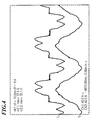
- ein Oszillogramm des Verbraucherstromes IV und des Netzstromes I0,
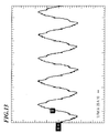
- Fig. 3
- ein Oszillogramm des Kompensationsstromes I1 und des Netzstromes I0,
- Fig. 4
- ein Oszillogramm des Verbraucherstromes IV und des Netzstromes I0,
- Fig. 5
- ein Oszillogramm des Kompensationsstromes I1 und des Netzstromes I0,
- Fig. 6 - 8
- Tabelle, Oszillogramm und Graphik des Oberschwingungsspektrums einer B6-Gleichrichterschaltung ohne erfindungsgemäße Schaltungsanordnung bei Teillastbedingungen,
- Fig. 9 - 11
- Tabelle, Oszillogramm und Graphik des Oberschwingungsspektrums einer B6-Gleichrichterschaltung ohne erfindungsgemäße Schaltungsanordnung bei Vollastbedingungen,
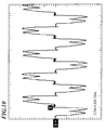
- Fig. 12 - 14
- Tabelle, Oszillogramm und Graphik des Oberschwingungsspektrums einer B6-Gleichrichterschaltung mit erfindungsgemäßer Schaltungsanordnung bei Teillastbedingungen und
- Fig. 15-17
- Tabelle, Oszillogramm und Graphik des Oberschwingungsspektrums einer B6-Gleichrichterschaltung mit erfindungsgemäßer Schaltungsanordnung bei Vollastbedingungen,
- Fig. 1
- 1 shows a schematic circuit diagram of a preferred embodiment of a circuit arrangement according to the invention,
- Fig. 2
- an oscillogram of the consumer current I V and the mains current I 0 ,
- Fig. 3
- an oscillogram of the compensation current I 1 and the mains current I 0 ,
- Fig. 4
- an oscillogram of the consumer current I V and the mains current I 0 ,
- Fig. 5
- an oscillogram of the compensation current I 1 and the mains current I 0 ,
- 6 - 8
- Table, oscillogram and graphic of the harmonic spectrum of a B6 rectifier circuit without circuit arrangement according to the invention under partial load conditions,
- Figures 9-11
- Table, oscillogram and graphic of the harmonic spectrum of a B6 rectifier circuit without circuit arrangement according to the invention under full load conditions,
- Figures 12-14
- Table, oscillogram and graphic of the harmonic spectrum of a B6 rectifier circuit with the circuit arrangement according to the invention under partial load conditions and
- Fig. 15-17
- Table, oscillogram and graphic of the harmonic spectrum of a B6 rectifier circuit with a circuit arrangement according to the invention under full load conditions,
Die in der Fig. 1 beispielhaft dargestellte bevorzugte Ausführungsform einer erfindungsgemäßen Schaltungsanordnung 10 für einen nichtlinearen Verbraucher 12 an einem Versorgungsnetz 14 mit drei Phasen 16, 18, 20 sowie einem Nulleiter 22 umfaßt für jede Phase 16, 18, 20 eine erste Induktivität 24 und eine erste Kapazität 26. Die erste Induktivität 24 umfaßt jeweils für jede Phase 16, 18, 20 eine erste Drosselspule 28 und eine zweite Drosselspule 30. Die Drosselspulen 28, 30 sowie die erste Kapazität 26 sind in Reihe geschaltet. Die jeweilige erste Drosselspule 28 ist mit der jeweiligen Phase 16, 18, 20 verbunden, die jeweilige zweite Drosselspule 30 ist an einer Seite mit der jeweiligen ersten Drosselspule 28 und an der anderen Seite mit der jeweiligen ersten Kapazität 26 verbunden. Die ersten Kapazitäten 26 sind an den jeweiligen von den zweiten Drosselspulen abgewandten Enden miteinander am Punkt 32 verbunden.The preferred embodiment of an embodiment of the invention shown by way of example in FIG. 1 Circuit arrangement 10 for a non-linear consumer 12 on a supply network 14 with three phases 16, 18, 20 and a neutral conductor 22 comprises a first inductance 24 and a first capacitance for each phase 16, 18, 20 26. The first inductor 24 comprises a first one for each phase 16, 18, 20 Choke coil 28 and a second choke coil 30. The choke coils 28, 30 and the first capacitance 26 are connected in series. The respective first choke coil 28 is connected to the respective phase 16, 18, 20, the respective second choke coil 30 is on one side with the respective first choke coil 28 and on the other side connected to the respective first capacitance 26. The first capacities 26 are facing away from the respective second choke coils Ends connected together at point 32.
Zwischen den ersten und zweiten Drosselspulen 28, 30 ist jeweils eine zweite Kapazität 34 angeschlossen. Auch die zweiten Kapazitäten 34 sind an ihren jeweiligen von den Drosselspulen 28, 30 abgewandten Enden an einem Punkt 36 miteinander verbunden. Aus dem Versorgungsnetz fließt der Netzstrom I0 und an den Verbraucher fließt der Verbraucherstrom IV. A second capacitance 34 is connected between the first and second choke coils 28, 30. The second capacitances 34 are also connected to one another at their respective ends facing away from the choke coils 28, 30 at a point 36. The mains current I 0 flows from the supply network and the consumer current I V flows to the consumer.
Eingeschleift in jede Phase 16, 18, 20 sind dritte Drosselspulen 38 zwischen dem Versorgungsnetz 14 und den Anschlußpunkten 40 der ersten Drosselspulen 28. Diese leisten ebenfalls einen Beitrag zur Wirkungsweise der erfindungsgemäßen Schaltungsanordnung 10.Loop in each phase 16, 18, 20 are third choke coils 38 between the Supply network 14 and the connection points 40 of the first choke coils 28. These also make a contribution to the mode of operation of the invention Circuit arrangement 10.
Diese Schaltungsanordnung 10 bewirkt, daß den oberschwingungsbehafteten Strömen IV des nichtlinearen Verbrauchers 12 je Phase ein Kompensationsstrom bzw. Reaktanzzweipolstrom I1 addiert und subtrahiert wird. Dies führt dazu, daß die dem Versorgungsnetz 14 entnommenen Ströme IV nur noch einen geringen Oberschwingungsanteil aufweisen.This circuit arrangement 10 causes the currents I V of the nonlinear consumer 12 which are subject to harmonics to be added and subtracted from each phase a compensation current or reactance two-pole current I 1 . This leads to the fact that the currents I V taken from the supply network 14 only have a small harmonic component.
In der Ausführungsform von Fig. 1 ist beispielhaft als nichtlinearer Verbraucher eine ungesteuerte B6-Gleichrichterschaltung mit einem Phasennennstrom von 35A vorgesehen, und die erfindungsgemäße Schaltungsanordnung 10 dementsprechend dimensioniert. Die erfindungsgemäße Schaltungsanordnung 10 umfaßt einen Reaktanzzweipol, der pro Phase 16, 18, 20 aus drei Induktivitäten 28, 30, 38 und zwei Kapazitäten 30, 34 besteht. Daraus folgt, daß die Funktion des Blindwiderstandes in Abhängigkeit von der Frequenz 6 Pole und Nullstellen aufweist und daß der Blindwiderstand positive und negative Werte annimmt, was einer Energieaufnahme und einer Energieabgabe entspricht.In the embodiment of Fig. 1 is exemplary as a non-linear consumer an uncontrolled B6 rectifier circuit with a nominal phase current of 35A is provided, and the circuit arrangement 10 according to the invention accordingly dimensioned. The circuit arrangement 10 according to the invention comprises a reactance dipole, which consists of three inductors 28, 30, 38 per phase 16, 18, 20 and two capacities 30, 34. It follows that the function of the reactance has 6 poles and zeros depending on the frequency and that the reactance takes positive and negative values, which means an energy consumption and corresponds to an energy output.
Die Kapazitätswerte der ersten und zweiten Kapazitäten 26, 34 sowie die Induktivitätswerte
der ersten, zweiten und dritten Drosselspulen 28, 30, 38 sind derart
dimensioniert, daß die Nullstellen und Pole der Funktion des Blindwiderstands auf
das jeweilige Oberschwingungsspektrum des Verbraucherstromes IV abgestimmt
sind. Nachfolgend sind lediglich beispielhaft konkrete Zahlenwerte für Induktivitäten
und Kapazitäten angeben. Diese lediglich beispielhafte Dimensionierung gilt
für einen Verbraucherstrom IV = 35A.
Die Induktivitäten 28, 30, 38 sind beispielsweise als dreiphasige Eisenkerndrosseln mit E-I-Kernschnitt ausgebildet. Diese Alternative stellt eine konstruktiv und kostenmäßig optimierte Ausführungsform für ein dreiphasiges Drosselsystem dar. Es ist allerdings auch möglich, komplexere Ausführungsformen für die Induktivitäten 28, 30, 38 einzusetzen, wie beispielsweise jeweils drei Einphasendrosseln anstelle einer Dreiphasendrossel mit E-I-Kernschnitt, sofern Bauraum und Kosten dies zulassen.The inductors 28, 30, 38 are, for example, as three-phase iron core chokes trained with E-I core cut. This alternative represents a constructive and Cost-optimized embodiment for a three-phase throttle system. However, it is also possible to use more complex embodiments for the inductors 28, 30, 38 to use, such as three single-phase chokes instead a three-phase choke with E-I core cut, provided space and costs allow this.
Mit der aus Fig. 1 ersichtlichen und oben beschriebenen bevorzugten Ausführungsform einer erfindungsgemäßen Schaltungsanordnung 10 wurden Versuche unternommen und die aus den Fig. 2 bis 5 ersichtlichen Ergebnisse erzielt. Wie man anhand der Oszillogramme der Fig. 2 bis 5 entnehmen kann, hat der Netzstrom einen THD = 9%, der Effektivwert des Netzstromes I0 ist gleich dem Effektivwert des Verbraucherstromes IV, der Effektivwert des Reaktanzzweipolstromes I1 beträgt (0,4 • Effektivwert) des Netzstromes im Maximum und der Netzstrom hat einen cos phi = 1. Ohne Reaktanzzweipolströme I1 ist der Verbraucherstrom cos phi = 0,95.Attempts have been made with the preferred embodiment of a circuit arrangement 10 according to the invention shown in FIG. 1 and described above and the results shown in FIGS. 2 to 5 have been achieved. As can be seen from the oscillograms of FIGS. 2 to 5, the mains current has a THD = 9%, the effective value of the mains current I 0 is equal to the effective value of the consumer current I V , the effective value of the reactance two-pole current I 1 is (0.4 • RMS value) of the mains current at the maximum and the mains current has a cos phi = 1. Without reactance two-pole currents I 1 , the consumer current cos phi = 0.95.
Die Versuchsergebnisse und Oszillogramme der Fig. 6 bis 17 stellen Oberschwingungsspektren der ungesteuerten B6-Gleichrichterschaltung mit erfindungsgemäßer Schaltungsanordnung (Fig. 12 bis 17) und zum Vergleich ohne die Schaltungsanordnung (Fig. 6 bis 11) dar. Hierbei veranschaulichen die Fig. 6 bis 8 und 12 bis 14 vergleichend Teillastbedingungen. Dagegen veranschaulichen die Fig. 9 bis 11 sowie 15 bis 17 Vollastbedingungen. Es ist unmittelbar offensichtlich, daß der Oberschwingungsanteil durch die Anwendung der erfindungsgemäßen Schaltungsanordnung 10 erheblich reduziert ist. Die Reduktion der Oberschwingungen ist für eine geräteseitige Kompensation mit lediglich passiven Bauteilen überraschend deutlich und stark ausgeprägt.The test results and oscillograms of FIGS. 6 to 17 represent harmonic spectra the uncontrolled B6 rectifier circuit with the inventive Circuit arrangement (Fig. 12 to 17) and for comparison without the circuit arrangement (Fig. 6 to 11). Here, Figs. 6 to 8 and 12 to 14 comparative part load conditions. In contrast, FIG. 9 illustrates to 11 and 15 to 17 full load conditions. It is immediately obvious that the harmonic component through the use of the circuit arrangement according to the invention 10 is significantly reduced. The reduction of harmonics is surprising for device-side compensation with only passive components clear and strong.
Die eingangs genannten Gleichrichter und Wechselrichter werden beispielsweise in Frequenzumrichtern, USV-Anlagen, Batterieladegeräten, Netzteilen, Gleichspannungsversorgungen, Stromrichtern, Gleichstromantrieben, Servoantrieben u.v.m. eingesetzt.The rectifiers and inverters mentioned at the beginning are, for example in frequency converters, UPS systems, battery chargers, power supplies, DC power supplies, Power converters, DC drives, servo drives u.v.m. used.
Claims (9)
dadurch gekennzeichnet ,daß
jede Phase (16, 18, 20) mit einer ersten Induktivität (24) verbunden ist, wobei jede erste Induktivität (24) mit ihrem von der jeweiligen Phase (16, 18, 20) abgewandten Ende wiederum mit einer ersten Kapazität (26) verbunden ist, wobei alle ersten Kapazitäten (26) an ihren jeweiligen von den ersten Induktivitäten (24) abgewandten Enden (32) miteinander verbunden sind.Circuit arrangement for harmonic compensation for nonlinear loads (12), in particular rectifiers or inverters, on at least two-phase, in particular three-phase supply networks (14) with sinusoidal mains voltage,
characterized in that
each phase (16, 18, 20) is connected to a first inductor (24), each first inductor (24) having its end facing away from the respective phase (16, 18, 20) in turn connected to a first capacitance (26) wherein all first capacitances (26) are connected to one another at their respective ends (32) facing away from the first inductances (24).
Applications Claiming Priority (2)
| Application Number | Priority Date | Filing Date | Title |
|---|---|---|---|
| DE20106008U | 2001-04-05 | ||
| DE20106008U DE20106008U1 (en) | 2001-04-05 | 2001-04-05 | Two-pole reactance circuit for non-linear consumers |
Publications (3)
| Publication Number | Publication Date |
|---|---|
| EP1248344A2 true EP1248344A2 (en) | 2002-10-09 |
| EP1248344A3 EP1248344A3 (en) | 2003-10-01 |
| EP1248344B1 EP1248344B1 (en) | 2006-06-28 |
Family
ID=7955402
Family Applications (1)
| Application Number | Title | Priority Date | Filing Date |
|---|---|---|---|
| EP02007520A Expired - Lifetime EP1248344B1 (en) | 2001-04-05 | 2002-04-02 | Bipolar reactance circuit for nonlinear loads |
Country Status (3)
| Country | Link |
|---|---|
| EP (1) | EP1248344B1 (en) |
| AT (1) | ATE332027T1 (en) |
| DE (2) | DE20106008U1 (en) |
Cited By (2)
| Publication number | Priority date | Publication date | Assignee | Title |
|---|---|---|---|---|
| EP1489728A2 (en) * | 2003-06-18 | 2004-12-22 | Alstom SA | Electric circuit for a voltage converter |
| DE102008035307A1 (en) | 2008-07-23 | 2010-01-28 | Block Transformatoren-Elektronik Gmbh & Co. Kg | Circuit arrangement for compensation of harmonics for e.g. throttle, on three-phase supply network, has filter branches with two capacitors, where capacitors are connected between ends of filter branches that are turned away from phases |
Families Citing this family (1)
| Publication number | Priority date | Publication date | Assignee | Title |
|---|---|---|---|---|
| US6844794B2 (en) * | 2002-10-08 | 2005-01-18 | Abb Oy | Harmonic mitigating filter |
Citations (2)
| Publication number | Priority date | Publication date | Assignee | Title |
|---|---|---|---|---|
| DE4219214A1 (en) * | 1992-06-12 | 1993-12-16 | Nord Systemtechnik | Attenuation circuit for signal harmonics - uses tuned filter coupled to tap-off of duplex filter inserted between current regulator and AC network |
| WO2000062396A1 (en) * | 1999-04-09 | 2000-10-19 | 1061933 Ontario Inc. | Universal harmonic mitigating system |
-
2001
- 2001-04-05 DE DE20106008U patent/DE20106008U1/en not_active Expired - Lifetime
-
2002
- 2002-04-02 DE DE50207352T patent/DE50207352D1/en not_active Expired - Lifetime
- 2002-04-02 AT AT02007520T patent/ATE332027T1/en active
- 2002-04-02 EP EP02007520A patent/EP1248344B1/en not_active Expired - Lifetime
Patent Citations (2)
| Publication number | Priority date | Publication date | Assignee | Title |
|---|---|---|---|---|
| DE4219214A1 (en) * | 1992-06-12 | 1993-12-16 | Nord Systemtechnik | Attenuation circuit for signal harmonics - uses tuned filter coupled to tap-off of duplex filter inserted between current regulator and AC network |
| WO2000062396A1 (en) * | 1999-04-09 | 2000-10-19 | 1061933 Ontario Inc. | Universal harmonic mitigating system |
Cited By (3)
| Publication number | Priority date | Publication date | Assignee | Title |
|---|---|---|---|---|
| EP1489728A2 (en) * | 2003-06-18 | 2004-12-22 | Alstom SA | Electric circuit for a voltage converter |
| EP1489728A3 (en) * | 2003-06-18 | 2006-03-15 | Alstom SA | Electric circuit for a voltage converter |
| DE102008035307A1 (en) | 2008-07-23 | 2010-01-28 | Block Transformatoren-Elektronik Gmbh & Co. Kg | Circuit arrangement for compensation of harmonics for e.g. throttle, on three-phase supply network, has filter branches with two capacitors, where capacitors are connected between ends of filter branches that are turned away from phases |
Also Published As
| Publication number | Publication date |
|---|---|
| EP1248344A3 (en) | 2003-10-01 |
| DE20106008U1 (en) | 2001-08-09 |
| EP1248344B1 (en) | 2006-06-28 |
| DE50207352D1 (en) | 2006-08-10 |
| ATE332027T1 (en) | 2006-07-15 |
Similar Documents
| Publication | Publication Date | Title |
|---|---|---|
| DE102017217132B3 (en) | Switching power supply with electrical circuitry for input protection circuit | |
| DE102008014898B4 (en) | Method for controlling a multiphase power converter with distributed energy stores at low output frequencies | |
| EP2831989B1 (en) | Rectifier circuit with current injection | |
| DE112011101193T5 (en) | Leakage current reduction device | |
| DE19908124C2 (en) | Inverters without harmonics | |
| WO2014202538A2 (en) | Power supply unit, in particular wide-range power supply unit | |
| EP1069673B1 (en) | Line filter | |
| EP0682402B1 (en) | Output magnitudes rise limiting device for self-commutated constant voltage intermediate circuit converter | |
| WO2009146961A1 (en) | Lossy triphase low-pass filter | |
| DE102005019215A1 (en) | Output filter for e.g. pulsed power converter, has filter chokes and filter condensers, which are interconnected as LC low pass, and circuit arrangement for dynamically and continuously reducing effectiveness of filter chokes and condensers | |
| AT516643B1 (en) | Rectifier circuit | |
| EP1248344A2 (en) | Bipolar reactance circuit for nonlinear loads | |
| AT514654B1 (en) | Rectifier circuit with current injection | |
| DE102019205946A1 (en) | Filter circuit to reduce the effects of a consumer on an energy supply | |
| DE102018010146A1 (en) | Device for filtering high-frequency interference voltages in a circuit for power factor correction | |
| DE2433825C3 (en) | Devices for supplying energy and improving the power factor of AC networks | |
| EP1619781B1 (en) | Circuitry for a converter | |
| DE2852066C2 (en) | ||
| DE202007001929U1 (en) | Harmonics compensation circuit for non-linear load, such as rectifier or inverter, has choke coils of phase inductance formed on section of core component for magnetic coupling | |
| WO2021174280A1 (en) | Converter assembly | |
| DE102014210562A1 (en) | DEVICE AND METHOD FOR A DRIVE SYSTEM WITH AN INPUT / RETRIEVABLE INVERTER | |
| DE3342011C2 (en) | Low pass filter for electrical consumers | |
| DE3635365A1 (en) | SECONDARY SWITCHABLE POWER SUPPLY | |
| DE2718598A1 (en) | Reduction of mains borne interference from rectifiers - using and stop filter consisting of capacitors, chokes and resistors connected to rectifier input to reduce current harmonics | |
| AT523974A1 (en) | DC-DC converter and converter arrangement with a DC-DC converter |
Legal Events
| Date | Code | Title | Description |
|---|---|---|---|
| PUAI | Public reference made under article 153(3) epc to a published international application that has entered the european phase |
Free format text: ORIGINAL CODE: 0009012 |
|
| AK | Designated contracting states |
Kind code of ref document: A2 Designated state(s): AT BE CH CY DE DK ES FI FR GB GR IE IT LI LU MC NL PT SE TR |
|
| AX | Request for extension of the european patent |
Free format text: AL;LT;LV;MK;RO;SI |
|
| PUAL | Search report despatched |
Free format text: ORIGINAL CODE: 0009013 |
|
| AK | Designated contracting states |
Kind code of ref document: A3 Designated state(s): AT BE CH CY DE DK ES FI FR GB GR IE IT LI LU MC NL PT SE TR |
|
| AX | Request for extension of the european patent |
Extension state: AL LT LV MK RO SI |
|
| 17P | Request for examination filed |
Effective date: 20040210 |
|
| AKX | Designation fees paid |
Designated state(s): AT BE CH CY DE DK ES FI FR GB GR IE IT LI LU MC NL PT SE TR |
|
| 17Q | First examination report despatched |
Effective date: 20040528 |
|
| GRAP | Despatch of communication of intention to grant a patent |
Free format text: ORIGINAL CODE: EPIDOSNIGR1 |
|
| GRAS | Grant fee paid |
Free format text: ORIGINAL CODE: EPIDOSNIGR3 |
|
| GRAA | (expected) grant |
Free format text: ORIGINAL CODE: 0009210 |
|
| AK | Designated contracting states |
Kind code of ref document: B1 Designated state(s): AT BE CH CY DE DK ES FI FR GB GR IE IT LI LU MC NL PT SE TR |
|
| PG25 | Lapsed in a contracting state [announced via postgrant information from national office to epo] |
Ref country code: IT Free format text: LAPSE BECAUSE OF FAILURE TO SUBMIT A TRANSLATION OF THE DESCRIPTION OR TO PAY THE FEE WITHIN THE PRESCRIBED TIME-LIMIT;WARNING: LAPSES OF ITALIAN PATENTS WITH EFFECTIVE DATE BEFORE 2007 MAY HAVE OCCURRED AT ANY TIME BEFORE 2007. THE CORRECT EFFECTIVE DATE MAY BE DIFFERENT FROM THE ONE RECORDED. Effective date: 20060628 Ref country code: FI Free format text: LAPSE BECAUSE OF FAILURE TO SUBMIT A TRANSLATION OF THE DESCRIPTION OR TO PAY THE FEE WITHIN THE PRESCRIBED TIME-LIMIT Effective date: 20060628 Ref country code: NL Free format text: LAPSE BECAUSE OF FAILURE TO SUBMIT A TRANSLATION OF THE DESCRIPTION OR TO PAY THE FEE WITHIN THE PRESCRIBED TIME-LIMIT Effective date: 20060628 Ref country code: IE Free format text: LAPSE BECAUSE OF FAILURE TO SUBMIT A TRANSLATION OF THE DESCRIPTION OR TO PAY THE FEE WITHIN THE PRESCRIBED TIME-LIMIT Effective date: 20060628 Ref country code: GB Free format text: LAPSE BECAUSE OF FAILURE TO SUBMIT A TRANSLATION OF THE DESCRIPTION OR TO PAY THE FEE WITHIN THE PRESCRIBED TIME-LIMIT Effective date: 20060628 |
|
| REG | Reference to a national code |
Ref country code: GB Ref legal event code: FG4D Free format text: NOT ENGLISH |
|
| REG | Reference to a national code |
Ref country code: CH Ref legal event code: EP |
|
| REG | Reference to a national code |
Ref country code: IE Ref legal event code: FG4D Free format text: LANGUAGE OF EP DOCUMENT: GERMAN |
|
| REF | Corresponds to: |
Ref document number: 50207352 Country of ref document: DE Date of ref document: 20060810 Kind code of ref document: P |
|
| PG25 | Lapsed in a contracting state [announced via postgrant information from national office to epo] |
Ref country code: DK Free format text: LAPSE BECAUSE OF FAILURE TO SUBMIT A TRANSLATION OF THE DESCRIPTION OR TO PAY THE FEE WITHIN THE PRESCRIBED TIME-LIMIT Effective date: 20060928 Ref country code: SE Free format text: LAPSE BECAUSE OF FAILURE TO SUBMIT A TRANSLATION OF THE DESCRIPTION OR TO PAY THE FEE WITHIN THE PRESCRIBED TIME-LIMIT Effective date: 20060928 |
|
| REG | Reference to a national code |
Ref country code: CH Ref legal event code: NV Representative=s name: HANS RUDOLF GACHNANG PATENTANWALT |
|
| PG25 | Lapsed in a contracting state [announced via postgrant information from national office to epo] |
Ref country code: ES Free format text: LAPSE BECAUSE OF FAILURE TO SUBMIT A TRANSLATION OF THE DESCRIPTION OR TO PAY THE FEE WITHIN THE PRESCRIBED TIME-LIMIT Effective date: 20061009 |
|
| PG25 | Lapsed in a contracting state [announced via postgrant information from national office to epo] |
Ref country code: PT Free format text: LAPSE BECAUSE OF FAILURE TO SUBMIT A TRANSLATION OF THE DESCRIPTION OR TO PAY THE FEE WITHIN THE PRESCRIBED TIME-LIMIT Effective date: 20061128 |
|
| NLV1 | Nl: lapsed or annulled due to failure to fulfill the requirements of art. 29p and 29m of the patents act | ||
| GBV | Gb: ep patent (uk) treated as always having been void in accordance with gb section 77(7)/1977 [no translation filed] |
Effective date: 20060628 |
|
| REG | Reference to a national code |
Ref country code: IE Ref legal event code: FD4D |
|
| PGFP | Annual fee paid to national office [announced via postgrant information from national office to epo] |
Ref country code: LU Payment date: 20070502 Year of fee payment: 6 |
|
| PLBE | No opposition filed within time limit |
Free format text: ORIGINAL CODE: 0009261 |
|
| STAA | Information on the status of an ep patent application or granted ep patent |
Free format text: STATUS: NO OPPOSITION FILED WITHIN TIME LIMIT |
|
| EN | Fr: translation not filed | ||
| 26N | No opposition filed |
Effective date: 20070329 |
|
| PGFP | Annual fee paid to national office [announced via postgrant information from national office to epo] |
Ref country code: CH Payment date: 20070618 Year of fee payment: 6 |
|
| BERE | Be: lapsed |
Owner name: ELTROPLAN-REVCON ELEKTROTECHNISCHE ANLAGEN G.M.B.H Effective date: 20070430 |
|
| PG25 | Lapsed in a contracting state [announced via postgrant information from national office to epo] |
Ref country code: BE Free format text: LAPSE BECAUSE OF NON-PAYMENT OF DUE FEES Effective date: 20070430 |
|
| PG25 | Lapsed in a contracting state [announced via postgrant information from national office to epo] |
Ref country code: FR Free format text: LAPSE BECAUSE OF FAILURE TO SUBMIT A TRANSLATION OF THE DESCRIPTION OR TO PAY THE FEE WITHIN THE PRESCRIBED TIME-LIMIT Effective date: 20070511 Ref country code: GR Free format text: LAPSE BECAUSE OF FAILURE TO SUBMIT A TRANSLATION OF THE DESCRIPTION OR TO PAY THE FEE WITHIN THE PRESCRIBED TIME-LIMIT Effective date: 20060929 |
|
| PG25 | Lapsed in a contracting state [announced via postgrant information from national office to epo] |
Ref country code: FR Free format text: LAPSE BECAUSE OF FAILURE TO SUBMIT A TRANSLATION OF THE DESCRIPTION OR TO PAY THE FEE WITHIN THE PRESCRIBED TIME-LIMIT Effective date: 20060628 |
|
| REG | Reference to a national code |
Ref country code: CH Ref legal event code: PL |
|
| PG25 | Lapsed in a contracting state [announced via postgrant information from national office to epo] |
Ref country code: LI Free format text: LAPSE BECAUSE OF NON-PAYMENT OF DUE FEES Effective date: 20080430 Ref country code: CH Free format text: LAPSE BECAUSE OF NON-PAYMENT OF DUE FEES Effective date: 20080430 |
|
| PG25 | Lapsed in a contracting state [announced via postgrant information from national office to epo] |
Ref country code: MC Free format text: LAPSE BECAUSE OF NON-PAYMENT OF DUE FEES Effective date: 20070430 |
|
| PG25 | Lapsed in a contracting state [announced via postgrant information from national office to epo] |
Ref country code: CY Free format text: LAPSE BECAUSE OF FAILURE TO SUBMIT A TRANSLATION OF THE DESCRIPTION OR TO PAY THE FEE WITHIN THE PRESCRIBED TIME-LIMIT Effective date: 20060628 |
|
| PG25 | Lapsed in a contracting state [announced via postgrant information from national office to epo] |
Ref country code: TR Free format text: LAPSE BECAUSE OF FAILURE TO SUBMIT A TRANSLATION OF THE DESCRIPTION OR TO PAY THE FEE WITHIN THE PRESCRIBED TIME-LIMIT Effective date: 20060628 |
|
| PG25 | Lapsed in a contracting state [announced via postgrant information from national office to epo] |
Ref country code: LU Free format text: LAPSE BECAUSE OF NON-PAYMENT OF DUE FEES Effective date: 20080402 |
|
| PGFP | Annual fee paid to national office [announced via postgrant information from national office to epo] |
Ref country code: DE Payment date: 20100630 Year of fee payment: 9 |
|
| PG25 | Lapsed in a contracting state [announced via postgrant information from national office to epo] |
Ref country code: DE Free format text: LAPSE BECAUSE OF NON-PAYMENT OF DUE FEES Effective date: 20111101 |
|
| REG | Reference to a national code |
Ref country code: DE Ref legal event code: R119 Ref document number: 50207352 Country of ref document: DE Effective date: 20111101 |
|
| PGFP | Annual fee paid to national office [announced via postgrant information from national office to epo] |
Ref country code: AT Payment date: 20120321 Year of fee payment: 11 |
|
| REG | Reference to a national code |
Ref country code: AT Ref legal event code: MM01 Ref document number: 332027 Country of ref document: AT Kind code of ref document: T Effective date: 20140402 |
|
| PG25 | Lapsed in a contracting state [announced via postgrant information from national office to epo] |
Ref country code: AT Free format text: LAPSE BECAUSE OF NON-PAYMENT OF DUE FEES Effective date: 20140402 |