EP1248256A2 - Magnetooptic recording medium and storing apparatus - Google Patents
Magnetooptic recording medium and storing apparatus Download PDFInfo
- Publication number
- EP1248256A2 EP1248256A2 EP01306821A EP01306821A EP1248256A2 EP 1248256 A2 EP1248256 A2 EP 1248256A2 EP 01306821 A EP01306821 A EP 01306821A EP 01306821 A EP01306821 A EP 01306821A EP 1248256 A2 EP1248256 A2 EP 1248256A2
- Authority
- EP
- European Patent Office
- Prior art keywords
- data
- reproducing
- recording
- area
- recorded
- Prior art date
- Legal status (The legal status is an assumption and is not a legal conclusion. Google has not performed a legal analysis and makes no representation as to the accuracy of the status listed.)
- Withdrawn
Links
Images




Classifications
-
- G—PHYSICS
- G11—INFORMATION STORAGE
- G11B—INFORMATION STORAGE BASED ON RELATIVE MOVEMENT BETWEEN RECORD CARRIER AND TRANSDUCER
- G11B11/00—Recording on or reproducing from the same record carrier wherein for these two operations the methods are covered by different main groups of groups G11B3/00 - G11B7/00 or by different subgroups of group G11B9/00; Record carriers therefor
- G11B11/10—Recording on or reproducing from the same record carrier wherein for these two operations the methods are covered by different main groups of groups G11B3/00 - G11B7/00 or by different subgroups of group G11B9/00; Record carriers therefor using recording by magnetic means or other means for magnetisation or demagnetisation of a record carrier, e.g. light induced spin magnetisation; Demagnetisation by thermal or stress means in the presence or not of an orienting magnetic field
- G11B11/105—Recording on or reproducing from the same record carrier wherein for these two operations the methods are covered by different main groups of groups G11B3/00 - G11B7/00 or by different subgroups of group G11B9/00; Record carriers therefor using recording by magnetic means or other means for magnetisation or demagnetisation of a record carrier, e.g. light induced spin magnetisation; Demagnetisation by thermal or stress means in the presence or not of an orienting magnetic field using a beam of light or a magnetic field for recording by change of magnetisation and a beam of light for reproducing, i.e. magneto-optical, e.g. light-induced thermomagnetic recording, spin magnetisation recording, Kerr or Faraday effect reproducing
- G11B11/10502—Recording on or reproducing from the same record carrier wherein for these two operations the methods are covered by different main groups of groups G11B3/00 - G11B7/00 or by different subgroups of group G11B9/00; Record carriers therefor using recording by magnetic means or other means for magnetisation or demagnetisation of a record carrier, e.g. light induced spin magnetisation; Demagnetisation by thermal or stress means in the presence or not of an orienting magnetic field using a beam of light or a magnetic field for recording by change of magnetisation and a beam of light for reproducing, i.e. magneto-optical, e.g. light-induced thermomagnetic recording, spin magnetisation recording, Kerr or Faraday effect reproducing characterised by the transducing operation to be executed
- G11B11/10526—Bulk initialisation or erasing, e.g. at least one whole information track with a single action
-
- G—PHYSICS
- G11—INFORMATION STORAGE
- G11B—INFORMATION STORAGE BASED ON RELATIVE MOVEMENT BETWEEN RECORD CARRIER AND TRANSDUCER
- G11B11/00—Recording on or reproducing from the same record carrier wherein for these two operations the methods are covered by different main groups of groups G11B3/00 - G11B7/00 or by different subgroups of group G11B9/00; Record carriers therefor
- G11B11/10—Recording on or reproducing from the same record carrier wherein for these two operations the methods are covered by different main groups of groups G11B3/00 - G11B7/00 or by different subgroups of group G11B9/00; Record carriers therefor using recording by magnetic means or other means for magnetisation or demagnetisation of a record carrier, e.g. light induced spin magnetisation; Demagnetisation by thermal or stress means in the presence or not of an orienting magnetic field
- G11B11/105—Recording on or reproducing from the same record carrier wherein for these two operations the methods are covered by different main groups of groups G11B3/00 - G11B7/00 or by different subgroups of group G11B9/00; Record carriers therefor using recording by magnetic means or other means for magnetisation or demagnetisation of a record carrier, e.g. light induced spin magnetisation; Demagnetisation by thermal or stress means in the presence or not of an orienting magnetic field using a beam of light or a magnetic field for recording by change of magnetisation and a beam of light for reproducing, i.e. magneto-optical, e.g. light-induced thermomagnetic recording, spin magnetisation recording, Kerr or Faraday effect reproducing
- G11B11/10502—Recording on or reproducing from the same record carrier wherein for these two operations the methods are covered by different main groups of groups G11B3/00 - G11B7/00 or by different subgroups of group G11B9/00; Record carriers therefor using recording by magnetic means or other means for magnetisation or demagnetisation of a record carrier, e.g. light induced spin magnetisation; Demagnetisation by thermal or stress means in the presence or not of an orienting magnetic field using a beam of light or a magnetic field for recording by change of magnetisation and a beam of light for reproducing, i.e. magneto-optical, e.g. light-induced thermomagnetic recording, spin magnetisation recording, Kerr or Faraday effect reproducing characterised by the transducing operation to be executed
- G11B11/10523—Initialising
-
- G—PHYSICS
- G11—INFORMATION STORAGE
- G11B—INFORMATION STORAGE BASED ON RELATIVE MOVEMENT BETWEEN RECORD CARRIER AND TRANSDUCER
- G11B11/00—Recording on or reproducing from the same record carrier wherein for these two operations the methods are covered by different main groups of groups G11B3/00 - G11B7/00 or by different subgroups of group G11B9/00; Record carriers therefor
- G11B11/10—Recording on or reproducing from the same record carrier wherein for these two operations the methods are covered by different main groups of groups G11B3/00 - G11B7/00 or by different subgroups of group G11B9/00; Record carriers therefor using recording by magnetic means or other means for magnetisation or demagnetisation of a record carrier, e.g. light induced spin magnetisation; Demagnetisation by thermal or stress means in the presence or not of an orienting magnetic field
- G11B11/105—Recording on or reproducing from the same record carrier wherein for these two operations the methods are covered by different main groups of groups G11B3/00 - G11B7/00 or by different subgroups of group G11B9/00; Record carriers therefor using recording by magnetic means or other means for magnetisation or demagnetisation of a record carrier, e.g. light induced spin magnetisation; Demagnetisation by thermal or stress means in the presence or not of an orienting magnetic field using a beam of light or a magnetic field for recording by change of magnetisation and a beam of light for reproducing, i.e. magneto-optical, e.g. light-induced thermomagnetic recording, spin magnetisation recording, Kerr or Faraday effect reproducing
- G11B11/10582—Record carriers characterised by the selection of the material or by the structure or form
-
- G—PHYSICS
- G11—INFORMATION STORAGE
- G11B—INFORMATION STORAGE BASED ON RELATIVE MOVEMENT BETWEEN RECORD CARRIER AND TRANSDUCER
- G11B11/00—Recording on or reproducing from the same record carrier wherein for these two operations the methods are covered by different main groups of groups G11B3/00 - G11B7/00 or by different subgroups of group G11B9/00; Record carriers therefor
- G11B11/10—Recording on or reproducing from the same record carrier wherein for these two operations the methods are covered by different main groups of groups G11B3/00 - G11B7/00 or by different subgroups of group G11B9/00; Record carriers therefor using recording by magnetic means or other means for magnetisation or demagnetisation of a record carrier, e.g. light induced spin magnetisation; Demagnetisation by thermal or stress means in the presence or not of an orienting magnetic field
- G11B11/105—Recording on or reproducing from the same record carrier wherein for these two operations the methods are covered by different main groups of groups G11B3/00 - G11B7/00 or by different subgroups of group G11B9/00; Record carriers therefor using recording by magnetic means or other means for magnetisation or demagnetisation of a record carrier, e.g. light induced spin magnetisation; Demagnetisation by thermal or stress means in the presence or not of an orienting magnetic field using a beam of light or a magnetic field for recording by change of magnetisation and a beam of light for reproducing, i.e. magneto-optical, e.g. light-induced thermomagnetic recording, spin magnetisation recording, Kerr or Faraday effect reproducing
- G11B11/10595—Control of operating function
- G11B11/10597—Adaptations for transducing various formats on the same or different carriers
-
- G—PHYSICS
- G11—INFORMATION STORAGE
- G11B—INFORMATION STORAGE BASED ON RELATIVE MOVEMENT BETWEEN RECORD CARRIER AND TRANSDUCER
- G11B11/00—Recording on or reproducing from the same record carrier wherein for these two operations the methods are covered by different main groups of groups G11B3/00 - G11B7/00 or by different subgroups of group G11B9/00; Record carriers therefor
- G11B11/10—Recording on or reproducing from the same record carrier wherein for these two operations the methods are covered by different main groups of groups G11B3/00 - G11B7/00 or by different subgroups of group G11B9/00; Record carriers therefor using recording by magnetic means or other means for magnetisation or demagnetisation of a record carrier, e.g. light induced spin magnetisation; Demagnetisation by thermal or stress means in the presence or not of an orienting magnetic field
- G11B11/105—Recording on or reproducing from the same record carrier wherein for these two operations the methods are covered by different main groups of groups G11B3/00 - G11B7/00 or by different subgroups of group G11B9/00; Record carriers therefor using recording by magnetic means or other means for magnetisation or demagnetisation of a record carrier, e.g. light induced spin magnetisation; Demagnetisation by thermal or stress means in the presence or not of an orienting magnetic field using a beam of light or a magnetic field for recording by change of magnetisation and a beam of light for reproducing, i.e. magneto-optical, e.g. light-induced thermomagnetic recording, spin magnetisation recording, Kerr or Faraday effect reproducing
- G11B11/10502—Recording on or reproducing from the same record carrier wherein for these two operations the methods are covered by different main groups of groups G11B3/00 - G11B7/00 or by different subgroups of group G11B9/00; Record carriers therefor using recording by magnetic means or other means for magnetisation or demagnetisation of a record carrier, e.g. light induced spin magnetisation; Demagnetisation by thermal or stress means in the presence or not of an orienting magnetic field using a beam of light or a magnetic field for recording by change of magnetisation and a beam of light for reproducing, i.e. magneto-optical, e.g. light-induced thermomagnetic recording, spin magnetisation recording, Kerr or Faraday effect reproducing characterised by the transducing operation to be executed
- G11B11/10515—Reproducing
-
- G—PHYSICS
- G11—INFORMATION STORAGE
- G11B—INFORMATION STORAGE BASED ON RELATIVE MOVEMENT BETWEEN RECORD CARRIER AND TRANSDUCER
- G11B11/00—Recording on or reproducing from the same record carrier wherein for these two operations the methods are covered by different main groups of groups G11B3/00 - G11B7/00 or by different subgroups of group G11B9/00; Record carriers therefor
- G11B11/10—Recording on or reproducing from the same record carrier wherein for these two operations the methods are covered by different main groups of groups G11B3/00 - G11B7/00 or by different subgroups of group G11B9/00; Record carriers therefor using recording by magnetic means or other means for magnetisation or demagnetisation of a record carrier, e.g. light induced spin magnetisation; Demagnetisation by thermal or stress means in the presence or not of an orienting magnetic field
- G11B11/105—Recording on or reproducing from the same record carrier wherein for these two operations the methods are covered by different main groups of groups G11B3/00 - G11B7/00 or by different subgroups of group G11B9/00; Record carriers therefor using recording by magnetic means or other means for magnetisation or demagnetisation of a record carrier, e.g. light induced spin magnetisation; Demagnetisation by thermal or stress means in the presence or not of an orienting magnetic field using a beam of light or a magnetic field for recording by change of magnetisation and a beam of light for reproducing, i.e. magneto-optical, e.g. light-induced thermomagnetic recording, spin magnetisation recording, Kerr or Faraday effect reproducing
- G11B11/10582—Record carriers characterised by the selection of the material or by the structure or form
- G11B11/10584—Record carriers characterised by the selection of the material or by the structure or form characterised by the form, e.g. comprising mechanical protection elements
Definitions
- the invention relates to a magnetooptic recording medium for recording and reproducing information by using a laser beam, and to a storing apparatus. More particularly, the invention relates to a magnetooptic recording medium for reproducing a recording mark smaller than beam spot of a laser beam by magnetically induced super resolution, and to a storing apparatus using such a medium.
- FIGs. 1A and 1B are diagrams showing a reproducing principle of the MSR technique.
- a medium construction a 3-layer construction of a recording (writing) layer 200, an intermediate layer 202, and a reproducing (reading) layer 204 will be described as an example.
- a mark recorded in the recording layer 200 is influenced in a low temperature portion in front of a beam spot 205 by a reproducing magnetic field, so that a front mask 206 is formed in the erasing direction.
- An arrow 216 indicates a medium rotating direction.
- the present invention may provide a magnetooptic recording medium and a storing apparatus in which enough reproducing power margin can be assured, even if a reproducing power of an ID area is small.
- a first aspect of the invention provides a magnetooptic recording medium in which at least a recording layer for recording data and a reproducing layer for reproducing the data recorded in the recording layer are formed on a substrate and the recorded data is reproduced by setting a proper reproducing laser power upon reproduction, wherein magnetizing directions of a buffer area, a sector address area, and a gap area which are sandwiched between data areas where the data is recorded are uniformly magnetized in the recording direction.
- the medium by uniformly magnetizing the buffer area, sector address area, and gap area which are sandwiched between the data areas in the recording direction, the medium enters a state where an aperture and a rear mask can be formed more easily, so that a medium can be provided in which even at the head of the data area without a preheating, MSR reproduction can be realized by a smaller reproducing power, and a reproducing power margin is wider.
- a second aspect of the invention provides a magnetooptic recording medium in which at least a recording layer for recording data and a reproducing layer for reproducing the data recorded in the recording layer are formed likewise on a substrate and the data is reproduced by setting a proper reproducing laser power upon reproduction, wherein a portion before a data area where the data is recorded is uniformly magnetized in a recording direction. That is, in this aspect, even if the portion just before the data area is merely uniformly magnetized in the recording direction instead of the whole area of a buffer area, a sector address area, and a gap area which are sandwiched between the data areas, the medium is put in a state where an aperture and a rear mask can be formed more easily. A medium is thus provided in which even at the head of the data area without a preheating, MSR reproduction can be realized by a smaller reproducing power, and a reproducing power margin is wider.
- a magnetooptic recording medium in which a mark of a recording layer is reflected from an aperture sandwiched between a front mask formed ahead of a reproducing beam in a reproducing layer and a rear mask formed behind the reproducing beam, and data is reproduced by MSR.
- the magnetooptic recording medium may be one in which a signal is recorded and reproduced onto/from one or both of lands and grooves which are formed alternately on the medium.
- the invention is suitable for use with a medium in which the signal is recorded and reproduced onto/from both of the lands and the grooves.
- a third aspect of the invention provides a storing apparatus, wherein at least a recording layer for recording data and a reproducing layer for reproducing the data recorded in the recording layer are formed on a substrate of a magnetooptic recording medium, and the storing apparatus comprises: a reproducing unit which reproduces the recorded data by setting a proper reproducing laser power upon reproduction; and a recovery processing unit which, when a predetermined recovery condition such as read error, temperature fluctuation, or the like occurs, uniformly magnetizes magnetizing directions of a buffer area, a sector address area, and a gap area which are sandwiched between data areas in which the data is recorded in the recording direction and, thereafter, retries the reproduction.
- a predetermined recovery condition such as read error, temperature fluctuation, or the like
- a fourth aspect of the invention provides a storing apparatus, wherein at least a recording layer for recording data and a reproducing layer for reproducing the data recorded in the recording layer are formed on a substrate of a magnetooptic recording medium, and the storing apparatus comprises: a reproducing unit which reproduces the recorded data by setting a proper reproducing laser power upon reproduction; and a recovery processing unit which, when a predetermined recovery condition such as read error, temperature fluctuation, or the like occurs, uniformly magnetizes a portion just before a data area where the data is recorded in the recording direction and, thereafter, retries the reproduction.
- a predetermined recovery condition such as read error, temperature fluctuation, or the like
- the reproducing unit reflects light off a mark in the recording layer from an aperture sandwiched between a front mask formed ahead of a reproducing beam in the reproducing layer and a rear mask formed behind the reproducing beam, and reproduces the data by MSR. Further, in this aspect, the reproducing unit reproduces a signal recorded on one or both of lands and grooves which are alternately formed on the magnetooptic recording medium.
- An embodiment of the invention provides a magnetooptic recording medium, wherein a portion of an emboss area (embossed area) or a space area before or after a data area where data is magnetooptically recorded is uniformly magnetized in the recording direction.
- the emboss areas located before and after the data area are emboss trains (pit trains) constructed by concave portions formed on the lands in the case of the land recording, emboss trains formed with convex portions on the groove so as to have a height up to a land surface in the case of the groove recording, or concave and convex emboss trains corresponding to the lands and grooves respectively in the case of the land/groove recording. All of them are concave and convex emboss trains.
- the space area is a flat area where no data is recorded, for example, a mirror surface area or a gap area.
- the position before the data area denotes a range where when the laser beam is located at the boundary of the data area, the portion in this range has to function as a rear mask when it is seen from the boundary.
- a storing apparatus having a format write processing unit which uniformly magnetizes a portion before or after a data area on a magnetooptic recording medium where data is recorded in the recording direction.
- this storing apparatus is used as a format writer (formatter) of the medium.
- FIG. 2 is an explanatory diagram showing an external view of a magnetooptic recording medium embodying the invention.
- a magnetooptic recording medium 10 of the invention is a magnetooptic disk medium having a diameter of, for example, 90 mm, has a memory capacity of, for example, 1.3 GB, and uses an MSR technique such as a double mask • rear aperture • detection.
- Fig. 3 is a close-up view of part of the medium, including an ID area on the recording surface of the magnetooptic recording medium 10 of Fig. 2.
- lands 12 and grooves 14 are alternately formed in the radial direction at regular intervals.
- ID areas 18 are formed in the circumferential direction at predetermined intervals.
- the ID area 18 is constructed by a buffer area 20, a sector address area 22, and a gap area 24 from the front side (i.e. the side facing a direction of rotation 25). Both sides of the ID area 18 correspond to data areas 16-1 and 16-2.
- Pit trains are formed in the sector address area 22 in the ID area 18.
- Figs. 4A and 4B show an initial state of a medium structure embodying the invention.
- Fig. 4A shows one of the tracks in Fig. 3.
- the ID area 18 is formed between the first data area 16-1 located in the rotating direction and the next data area 16-2.
- the ID area 18 is constructed by the buffer area 20, sector address area 22, and gap area 24 in order from the front side.
- Fig. 4B shows a cross sectional structure of the medium comprising a recording layer 26, an intermediate layer 28, and a reproducing layer 30.
- the recording is performed at a recording density that is equal to or higher than a cut-off frequency.
- the data recorded at the recording density that is equal to or higher than the cut-off frequency can be reproduced by the MSR.
- each layer of the magnetooptic recording medium in this embodiment is as follows.
- the recording layer 26 is constructed by Tb of 22 weight %, Fe of 66 weight %, and Co of 12 weight %.
- the intermediate layer 28 is constructed by Gd of 28 weight % and Fe of 72 weight %.
- the reproducing layer 30 is constructed by Gd of 21 weight %, Fe of 60 weight %, and Co of 19 weight %.
- initialization of the medium is performed in a recording direction 32 just after the manufacturing. That is, a magnetic field larger than a coercive force of the medium is applied and the whole surface of the medium is magnetized in the uniform direction, namely, the recording direction 32.
- a micro magnetic domain which would be a cause of noise, is eliminated.
- the medium is initialized in the recording direction 32 at a stage just after the manufacturing.
- the ID area 18 constructed by the buffer area 20, sector address area 22, and gap area 24 sandwiched between the data areas 16-1 and 16-2 where the data is recorded, has been magnetized in the recording direction 32.
- the medium is initialized in an erasing direction 34 just after manufacture as shown in Figs. 5A and 5B. Therefore, in a recording/reproducing state of the magnetooptic recording medium, the ID area 18 existing between the data areas 16-1 and 16-2 has been magnetized in the erasing direction 34.
- Figs. 6A to 6C show a reproducing principle of the magnetooptic recording medium of the invention. That is, Fig. 6A shows a plan view of three tracks. Fig. 6B shows a formatting state in the tracking (rotation) direction. Further, Fig. 6C shows a medium structure.
- a recording mark is read from an aperture 42 sandwiched by a front mask 36 ahead of a beam spot 35 and a rear mask 40 behind the beam spot 35.
- the reproducing power margin particularly, to widen the reproducing power margin on the low power side, it is sufficient to set a magnetizing state where the aperture 42 subsequent to the front mask 36 can be easily formed.
- Fig. 7 shows a detailed state of magnetization in the conventional magnetooptic recording medium in Figs. 5A and 5B.
- Fig. 8 shows details of the state of magnetization of a medium embodying the present invention.
- the recording layer 26 and reproducing layer 30 become TM-rich in which the greater part is occupied by the magnetizing state by transition metal TM of Fe and Co.
- the intermediate layer 28 becomes RE-rich in which a principal part of the magnetization structure is occupied by a rare earth metal.
- TM magnetizing direction 48 when the transition metal TM serving as a switched connection, that is, the magnetization of lead or cobalt is confirmed in the area of the front mask 36, as shown in a TM magnetizing direction 48, all of the layers of the recording layer 26, intermediate layer 28, and reproducing layer 30 are directed to the same TM magnetizing direction 48, a magnetic domain wall as a boundary between the magnetic domain of the recording layer 26 and the magnetic domain of the intermediate layer 28 does not exist, and it will be understood that the medium is in a stable state, that is, a state where the aperture 42 is difficult to form.
- each of arrows 44 and 46 indicates a synthesis magnetizing direction (magnetizing direction of TM + RE) of the transition metal TM and rare earth RE.
- the magnetooptic recording medium embodying the invention in Fig. 8 when the magnetization of the transition metal TM serving as a switching connection in the area of the front mask 36 is confirmed, the magnetizing directions are different (for example, a TM magnetizing direction 50 and the TM magnetizing direction 48) in the recording layer 26 and intermediate layer 28. Therefore, the magnetic domain is formed at the boundary between the recording layer 26 and intermediate layer 28. It will be understood that the medium is in an unstable state as compared with that of the magnetization structure of the conventional medium of Fig. 7. Therefore, at the boundary between the front mask 36 and aperture 42, the magnetizing state of the magnetooptic recording medium of Fig. 8 can be more easily changed for the temperature (with temperature) by the reproducing beam. Consequently, the reproducing power margin can be widened.
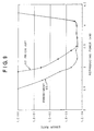
- Fig. 9 shows the reproducing power margin of the recording medium of this embodiment in comparison with that of the conventional medium.
- the power margin 60 in the invention is widened by about 0.5 mW toward the low power side, compared with the power margin 62 of the conventional medium. It can be confirmed that the reproducing power margin has been widened by initializing the ID area sandwiched by the data areas in the recording direction.
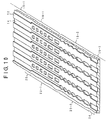
- Fig. 10 is a close-up view of an ID area in another embodiment of the magnetooptic recording medium according to the invention.
- a land/groove magnetooptic disk medium for performing recording onto both the lands and the grooves will be described as an example.
- the ID area sandwiched by the data areas 16-1 and 16-2 is constructed by: a land ID area 18-1 where pits have been formed on the lands 12; and a groove ID area 18-2 where pits have been formed on the grooves 14.
- a detailed structure of the land ID area 18-1 and groove ID area 18-2 will now be described.
- a land sector address area 22-1 is provided after the buffer area 20. Subsequently, a groove sector address area 22-2 is formed. Further, the gap area 24 is provided.
- the reproducing power margin can be widened toward a low power side, like the reproducing power margin 60 mentioned above, as compared with power margin 62 in Fig. 9.
- the reproducing power margin As mentioned above, in case of the land/groove magnetooptic recording medium in which the signal can be stored on the lands and grooves in Fig. 10, it is influenced more easily by crosstalk at the high reproducing power and there is a limitation that a large reproducing power cannot be obtained.
- the whole ID area including the buffer area, sector address area, and gap area other than the data areas has been magnetized in the recording direction, with respect to the improvement of the reproducing power margin according to the invention, if the magnetizing state of the portion just before the data area 16-2 in Figs. 3 and 10 is set in the recording direction, sufficient enlargement of the reproducing power margin toward the low power side as shown in Fig. 9 can be derived.
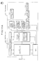
- Figs. 11A and 11B are block diagrams of an optical disk drive as a storing apparatus of the invention.
- a magnetooptic disk (MO) cartridge is used as an example of the magnetooptic recording medium.
- the optical disk drive is a drive which can perform recording and reproduction (writing and reading of data) using the lands, lands/grooves, or grooves of the medium, and is constructed by a controller 100 and an enclosure 102.
- the controller 100 has: an MPU 114 for performing overall control; an interface controller 116 for performing transmission and reception of data to/from a host; an optical disk controller (ODC) 118 having a formatter and an ECC function which are necessary for reading and writing of the medium; and a buffer memory 120.
- ODC optical disk controller
- an encoder 122 is provided for the optical disk controller 118.
- a reading system for the ODC 118 a detector 132, a head amplifier 134, a read LSI circuit 128, and a decoder 126 are provided. Further, a laser diode control circuit 124 and a laser diode unit 130 are provided.
- the detector 132 receives return light from the magnetooptic disk and outputs an ID signal and an MO signal to the read LSI circuit 128 through the head amplifier 134.
- the read LSI circuit 128 forms a read clock and read data from the inputted ID signal and MO signal and outputs them to the decoder 126.
- the ambient temperature within the apparatus detected by a temperature sensor 136 is inputted to the MPU 114.
- a light emitting power in the laser diode unit 130 is optimized on the basis of the ambient temperature.
- the MPU 114 controls a spindle motor 140 through a driver 138 and controls an electromagnet 144 through a driver 142.
- the electromagnet 144 supplies an external magnetic field upon recording and erasure of the MO cartridge. In case of a magnetically induced super resolution magnetooptic medium (MSR medium) of a capacity such as 1.3 GB, the external magnetic field is also supplied upon reproduction.
- MSR medium magnetically induced super resolution magnetooptic medium
- a DSP 115 performs a servo control for positioning an objective lens mounted in a head actuator to a target position on the magnetooptic disk on the basis of a servo error signal.
- the servo control has two functions of a tracking control for positioning the objective lens to the target track position on the medium and a focusing control for controlling the objective lens to a focal position on the medium.
- a photodetector 146, a focusing error signal detecting circuit (FES detecting circuit) 148, a tracking error signal detecting circuit (TES detecting circuit) 150, and a track zero-cross point detecting circuit (TZC detecting circuit) 152 are provided.
- the FES detecting circuit 148 forms a focusing error signal by, for example, a knife edge method as a focusing optical system.
- the DSP 115 drives a focusing actuator 156 by a driver 154 with respect to the focusing control, thereby positioning the objective lens to the focal position in the optical axial direction.
- the DSP 115 drives a head actuator 160 using a VCM by a driver 158, thereby positioning the objective lens to a target track center on the medium.
- a recovery processing unit 104 is provided for the MPU 114.
- a formatting operation for initializing the ID area of the magnetooptic recording medium in the recording direction is executed and the reproducing power margin is enlarged, thereby coping with read errors or fluctuation of the temperature in the apparatus.
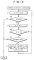
- Fig. 12 is a flowchart for a read error recovery process in the case where a magnetooptic recording medium in which the ID area between the data areas has been initialized in the recording direction, as described above, is used in the magnetooptic disk drive in Figs. 11A and 11B.
- the error recovery process is made operative when a read error is caused during reproduction by the MSR.
- a retry read (retry reading operation) is executed. If the error recurs in the retry read in step S2, a count value of a counter N is increased by "1" in step S3. After that, whether the count value of the retry counter N has reached the number (A) of retry times or not is discriminated in step S4.
- a read error is changed to a state of a successful read, owing to the enlargement of the reproducing power margin, and error recovery can be completed.
- a magnetooptic recording medium to which the error recovery process in Figs. 11A and 11B is executed when the read error occurred with respect to the conventional magnetooptic recording medium in which the ID area has already been initialized in the erasing direction at the stage of manufacturing, by executing the error recovery process in Figs. 11A and 11B, a proper recovery can be accomplished.
- the formatting to initialize the ID area in the recording direction is executed again as an error recovery, so that the initialization in the recording direction is updated and by returning the reproducing power margin to the initial state, the possibility of error recovery is raised.
- Fig. 13 is a flowchart for a temperature recovery process by the magnetooptic disk drive in Figs. 11A and 11B.
- the temperature in the apparatus is read in step S1 in accordance with a predetermined time schedule. Whether a temperature change is large or not is discriminated in step S2 from a temperature difference between the previous temperature in the apparatus and the present read temperature in the apparatus. If the temperature change is large, step S3 follows.
- the formatting to initialize the ID area on the magnetooptic recording medium in the recording direction is executed, thereby enlarging the reproducing power margin. Further, besides the formatting to initialize the ID area on the recording medium in the recording direction, such as the error recovery process in Fig. 12 or temperature recovery process in Fig. 13, it is also possible to execute a formatting for initializing the ID area in the recording direction in the formatting process of the magnetooptic recording medium.
- either the buffer area, sector address area, and gap area sandwiched between the data areas, or the portion just before the data area, are/is uniformly magnetized in the recording direction, so that the medium is put into a state where the aperture and the rear mask can be formed more easily at the head position of the data area.
- a medium can thus be provided in which, even at the head of the data area of small preheating, MSR reproduction can be realized with a smaller reproducing power and wider reproducing power margin.
- the invention can be also similarly applied to a land/groove recording medium in which the signal is recorded on both the lands 12 and grooves 14 in Fig. 10, or to a groove-type medium in which the signal is recorded on the grooves 14.
- the ID area on the medium of Fig. 3 or 10 is not limited to that in the embodiment but can be also replaced with an emboss train comprising concave portions of an arbitrary shape formed on the lands in case of the land recording, an emboss train comprising convex portions of an arbitrary shape formed on the grooves so as to be raised up to the land surface in case of the groove recording, or alternatively, an emboss train comprising concave or convex portions corresponding to each of the lands and grooves in case of the land/groove recording.
- the emboss areas are optical reproducing areas for optically reproducing the signal, while the data area is a magnetooptic reproducing area for magnetooptically reproducing the signal.
- the functions of a format writer which is used in the manufacturing line of the magnetooptic recording medium of the invention can be also realized.
- the functions of a format writer are realized as a format processing unit by executing a program of the MPU 114 provided also for the controller 100 in Figs. 11A and 11B.
- the front or rear portion of the data area on the magnetooptic recording medium where the data is recorded is uniformly magnetized in the recording direction.
Abstract
Description
Claims (10)
- A magnetooptic recording medium in which at least a recording layer for recording data and a reproducing layer for reproducing the data recorded in said recording layer are formed on a substrate, and the recorded data is reproduced by setting a proper reproducing laser power upon reproduction, wherein
magnetizing directions of a buffer area, a sector address area, and a gap area, which are sandwiched between data areas where the data is recorded, are uniformly magnetized in a recording direction. - A magnetooptic recording medium in which at least a recording layer for recording data and a reproducing layer for reproducing the data recorded in said recording layer are formed on a substrate, and the recorded data is reproduced by setting a proper reproducing laser power upon reproduction, wherein
a front portion of a data area in which the data is recorded is uniformly magnetized in a recording direction. - A medium according to claim 1 or 2, wherein a mark in said recording layer is reflected from an aperture sandwiched between a front mask formed ahead of a reproducing beam in said reproducing layer and a rear mask formed behind the reproducing beam, and the data is reproduced by an MSR (Magnetically Induced Super Resolution).
- A medium according to claim 1, 2, or 3, wherein a signal is recorded and reproduced onto/from one or both of lands and grooves formed alternately on the medium.
- A storing apparatus, whereinat least a recording layer for recording data and a reproducing layer for reproducing the data recorded in said recording layer are formed on a substrate of a magnetooptic recording medium, andsaid storing apparatus comprises:a reproducing unit which reproduces the recorded data by setting a proper reproducing laser power upon reproduction; anda recovery processing unit which, when a predetermined recovery condition such as read error, temperature fluctuation, or the like occurs, uniformly magnetizes magnetizing directions of a buffer area, a sector address area, and a gap area which are sandwiched between data areas in which the data is recorded in a recording direction and, thereafter, retries the reproduction.
- A storing apparatus, whereinat least a recording layer for recording data and a reproducing layer for reproducing the data recorded in said recording layer are formed on a substrate of a magnetooptic recording medium, andsaid storing apparatus comprises:a reproducing unit which reproduces the recorded data by setting a proper reproducing laser power upon reproduction; anda recovery processing unit which, when a predetermined recovery condition such as read error, temperature fluctuation, or the like occurs, uniformly magnetizes a front portion of a data area in which the data is recorded in a recording direction and, thereafter, retries the reproduction.
- An apparatus according to claim 5 or 6, wherein said reproducing unit reflects a mark in said recording layer from an aperture sandwiched between a front mask formed ahead of a reproducing beam in said reproducing layer and a rear mask formed behind the reproducing beam and reproduces the data by an MSR (Magnetically Induced Super Resolution).
- An apparatus according to claim 5, 6, or 7, wherein said reproducing unit reproduces a signal recorded on one or both of lands and grooves formed alternately on said magnetooptic recording medium.
- A magnetooptic recording medium, wherein a portion of an emboss area or a space area before or after a data area in which data is magnetooptically recorded is uniformly magnetized in a recording direction.
- A storing apparatus comprising a format write processing unit which uniformly magnetizes a portion before or after a data area on a magnetooptic recording medium in which data is recorded in a recording direction.
Applications Claiming Priority (2)
| Application Number | Priority Date | Filing Date | Title |
|---|---|---|---|
| JP2001106789 | 2001-04-05 | ||
| JP2001106789A JP2002304786A (en) | 2001-04-05 | 2001-04-05 | Magneto-optical recording medium and storage device |
Publications (2)
| Publication Number | Publication Date |
|---|---|
| EP1248256A2 true EP1248256A2 (en) | 2002-10-09 |
| EP1248256A3 EP1248256A3 (en) | 2005-01-05 |
Family
ID=18959238
Family Applications (1)
| Application Number | Title | Priority Date | Filing Date |
|---|---|---|---|
| EP01306821A Withdrawn EP1248256A3 (en) | 2001-04-05 | 2001-08-09 | Magnetooptic recording medium and storing apparatus |
Country Status (3)
| Country | Link |
|---|---|
| US (2) | US6901034B2 (en) |
| EP (1) | EP1248256A3 (en) |
| JP (1) | JP2002304786A (en) |
Cited By (2)
| Publication number | Priority date | Publication date | Assignee | Title |
|---|---|---|---|---|
| EP1262958A3 (en) * | 2001-05-30 | 2005-09-14 | Fujitsu Limited | Reproducing method and storage apparatus |
| EP2378521A1 (en) * | 2010-04-13 | 2011-10-19 | Thomson Licensing | Laser power management for Super-RENS optical recording media |
Families Citing this family (3)
| Publication number | Priority date | Publication date | Assignee | Title |
|---|---|---|---|---|
| CN100501658C (en) * | 2002-12-20 | 2009-06-17 | 皇家飞利浦电子股份有限公司 | Power saving method for portable streaming devices and related equipment |
| US7498092B2 (en) * | 2005-01-26 | 2009-03-03 | Hitachi Global Storage Technologies Netherlands B.V. | Perpendicular magnetic recording medium with magnetic torque layer coupled to the perpendicular recording layer |
| US7602296B2 (en) | 2006-06-02 | 2009-10-13 | Ulibarri Giovanni M | System and method for transport security control and tracking |
Family Cites Families (17)
| Publication number | Priority date | Publication date | Assignee | Title |
|---|---|---|---|---|
| JPH05225627A (en) * | 1992-02-14 | 1993-09-03 | Fujitsu Ltd | High density magneto-optical disk |
| JP3230388B2 (en) | 1994-03-15 | 2001-11-19 | 富士通株式会社 | Magneto-optical recording medium and method of reproducing information recorded on the medium |
| JPH07320320A (en) | 1994-05-24 | 1995-12-08 | Sharp Corp | Magneto-optical recording medium, magneto-optical recording method, and magneto-optical recording information reproducing method |
| JP3572686B2 (en) | 1994-11-24 | 2004-10-06 | 東ソー株式会社 | Information recording medium and reproducing method thereof |
| JP3177395B2 (en) * | 1995-01-31 | 2001-06-18 | シャープ株式会社 | Magneto-optical recording medium and reproducing method thereof |
| JP3557770B2 (en) | 1995-02-22 | 2004-08-25 | セイコーエプソン株式会社 | High density optical disk and reproducing method thereof |
| JP3249713B2 (en) | 1995-06-09 | 2002-01-21 | シャープ株式会社 | Magneto-optical recording medium and recording method thereof |
| JPH0954993A (en) * | 1995-08-15 | 1997-02-25 | Canon Inc | Magneto-optical recording medium and information reproducing method of the medium |
| JP2969256B2 (en) | 1995-09-22 | 1999-11-02 | 富士通株式会社 | Optical recording medium and reproducing method thereof |
| JP3063598B2 (en) * | 1995-12-01 | 2000-07-12 | 三菱電機株式会社 | Optical disk and optical disk device |
| JP3424037B2 (en) | 1996-04-05 | 2003-07-07 | 富士通株式会社 | Information reproducing method and information recording method for magneto-optical recording medium, and magneto-optical reproducing apparatus |
| JPH10134429A (en) * | 1996-10-25 | 1998-05-22 | Fujitsu Ltd | Magneto-optical recording medium and reproducing method thereof |
| JPH10188385A (en) * | 1996-12-17 | 1998-07-21 | Fujitsu Ltd | Method and apparatus for reproducing magneto-optical recording medium |
| JP3538727B2 (en) * | 1997-10-01 | 2004-06-14 | 富士通株式会社 | Magneto-optical recording medium |
| JP2000057646A (en) | 1998-08-07 | 2000-02-25 | Sony Corp | Magneto-optical recording medium and magneto-optical recording / reproducing apparatus |
| JP4183868B2 (en) * | 1999-12-07 | 2008-11-19 | 富士通株式会社 | Optical storage device |
| JP2002050090A (en) * | 2000-05-25 | 2002-02-15 | Fujitsu Ltd | Optical recording medium |
-
2001
- 2001-04-05 JP JP2001106789A patent/JP2002304786A/en active Pending
- 2001-08-03 US US09/921,523 patent/US6901034B2/en not_active Expired - Fee Related
- 2001-08-09 EP EP01306821A patent/EP1248256A3/en not_active Withdrawn
-
2005
- 2005-04-14 US US11/105,846 patent/US7133330B2/en not_active Expired - Fee Related
Cited By (4)
| Publication number | Priority date | Publication date | Assignee | Title |
|---|---|---|---|---|
| EP1262958A3 (en) * | 2001-05-30 | 2005-09-14 | Fujitsu Limited | Reproducing method and storage apparatus |
| EP2378521A1 (en) * | 2010-04-13 | 2011-10-19 | Thomson Licensing | Laser power management for Super-RENS optical recording media |
| EP2378520A1 (en) * | 2010-04-13 | 2011-10-19 | Thomson Licensing | Laser power management for Super-RENS optical recording media |
| US8605554B2 (en) | 2010-04-13 | 2013-12-10 | Thomson Licensing | Laser power management for super-RENS optical recording media |
Also Published As
| Publication number | Publication date |
|---|---|
| EP1248256A3 (en) | 2005-01-05 |
| JP2002304786A (en) | 2002-10-18 |
| US20050180269A1 (en) | 2005-08-18 |
| US7133330B2 (en) | 2006-11-07 |
| US20020150001A1 (en) | 2002-10-17 |
| US6901034B2 (en) | 2005-05-31 |
Similar Documents
| Publication | Publication Date | Title |
|---|---|---|
| JPH0689473A (en) | Magneto-optical recording medium | |
| JP2002015507A (en) | Data recording method and disk device | |
| EP0498459A2 (en) | Magneto-optical medium and recording and/or reproducing apparatus thereof | |
| US20050281177A1 (en) | High track density super resolution mo-rom medium | |
| US6449231B1 (en) | Storage unit, optical recording medium and information recording method | |
| US7355929B2 (en) | Magneto-optical disk and recording and/or reproducing method and recording and/or reproducing apparatus using the magneto-optical disk | |
| JP2002050090A (en) | Optical recording medium | |
| US6901034B2 (en) | Magneto-optical storage medium having data in uniform magnetized recording direction | |
| US6385144B1 (en) | Storage device with means for efficiently positioning a head on a disk including guard areas lacking position information | |
| JP4183868B2 (en) | Optical storage device | |
| US6535463B2 (en) | Method and apparatus for high density recording of data on a disk, and recording medium produced thereby | |
| CN1307634C (en) | Optical recording medium and optical recording device | |
| JP3776711B2 (en) | Reproduction laser power setting method and optical storage device | |
| JP3381500B2 (en) | Information recording / reproducing apparatus and optical recording medium reproducing method | |
| JP3958766B2 (en) | Optical storage | |
| JP2883101B2 (en) | Information recording device | |
| JP2004071153A (en) | Optical disk drive | |
| JP2005093063A (en) | Storage device, optical recording medium, and information recording method | |
| JPH06349073A (en) | Optical disk and information recording and reproducing device | |
| Yamamoto et al. | 3-Beam magneto-optical disk drive | |
| JPH04259943A (en) | Recording and reproducing device for magneto-optical disk | |
| JPH09190669A (en) | Information reproducing apparatus and optical recording medium reproducing method | |
| JPH0744872A (en) | Optical information recording medium and optical information recording / reproducing apparatus | |
| JPH11250519A (en) | Optical recording medium reproducing apparatus and reproducing method | |
| JP2002133785A (en) | Data recording / reproducing method, data processing device and recording medium |
Legal Events
| Date | Code | Title | Description |
|---|---|---|---|
| PUAI | Public reference made under article 153(3) epc to a published international application that has entered the european phase |
Free format text: ORIGINAL CODE: 0009012 |
|
| AK | Designated contracting states |
Kind code of ref document: A2 Designated state(s): AT BE CH CY DE DK ES FI FR GB GR IE IT LI LU MC NL PT SE TR |
|
| AX | Request for extension of the european patent |
Free format text: AL;LT;LV;MK;RO;SI |
|
| PUAL | Search report despatched |
Free format text: ORIGINAL CODE: 0009013 |
|
| AK | Designated contracting states |
Kind code of ref document: A3 Designated state(s): AT BE CH CY DE DK ES FI FR GB GR IE IT LI LU MC NL PT SE TR |
|
| AX | Request for extension of the european patent |
Extension state: AL LT LV MK RO SI |
|
| 17P | Request for examination filed |
Effective date: 20050504 |
|
| AKX | Designation fees paid |
Designated state(s): DE FR GB |
|
| 17Q | First examination report despatched |
Effective date: 20080215 |
|
| GRAP | Despatch of communication of intention to grant a patent |
Free format text: ORIGINAL CODE: EPIDOSNIGR1 |
|
| STAA | Information on the status of an ep patent application or granted ep patent |
Free format text: STATUS: THE APPLICATION IS DEEMED TO BE WITHDRAWN |
|
| 18D | Application deemed to be withdrawn |
Effective date: 20091104 |