This invention relates to a multibeam scanning
optical system and an image forming apparatus using
the same, and particularly is suitable, for example,
for a laser beam printer (LBP), a digital copying
machine or the like using a plurality of light
sources as a light source to achieve a high speed and
high recording density.
Related Background Art
In an image forming apparatus using a multibeam
scanning optical system applied to a laser beam
printer, a digital copying machine or the like, a
plurality of beams emitted from a plurality of
different light emitting points (laser beam sources)
are directed as a plurality of light spots to
different positions separate from one another in a
sub scanning direction on the surface of a recording
medium such as a photosensitive member which is a
surface to be scanned, by a common multibeam scanning
optical system comprised of a light deflector such as
a rotary polygon mirror and an f lens or the like,
and the surface of the recording medium is scanned at
a time in a main scanning direction to thereby effect
the recording of image information.
In such a conventional image forming apparatus,
the distance in the sub scanning direction between
adjacent spots scanned at a time, in other words, the
scanning line pitch by the plurality of spots, must
be adjusted with good accuracy.
Also, in recent image forming apparatuses, it
is intended to make the resolution of an output image
variable, and from such a point of view, it is
desirable that the width of a plurality of scanning
line pitches scanned at a time on the surface of a
recording medium in the main scanning direction can
be changed.
Further, recently, high recording density and a
high-speed output have been more required, and it has
become necessary to increase the number of the light
emitting points of a multibeam scanning optical
system in an image forming apparatus to 2, 3, 4, ... .
Heretofore, to adjust or change the scanning
line pitch by a plurality of spots, a light source
unit comprised of a plurality of light sources and a
beam combining prism or the like has been rotated
about the optical axis of an optical system in a
plane perpendicular to the optical axis. A multibeam
scanning apparatus of this kind is proposed, for
example, in Japanese Patent Application Laid-Open No.
7-181412.
The adjusting method for the scanning line
pitch in the above-mentioned publication, however, is
of a construction in which the light source unit
comprised of a plurality of light sources and a beam
combining prism or the like is rotated about the
optical axis of the optical system in the plane
perpendicular to the optical axis and therefore,
suffers from the problem that the scanning line pitch
is liable to vary for mechanical vibration or the
like. Also, the laser beam sources such as
semiconductor lasers are fixed to a movable portion,
and this also leads to the problem of insufficient stability to
environmental fluctuations (e.g. changes in
temperature, etc.) and the pitch interval is
liable to change with the environmental fluctuations.
It is an object of the present invention to
provide a multibeam scanning optical system which is
strong against mechanical vibration or the like and
suffers little from pitch fluctuation and which is
excellent in environmental stability, and an image
forming apparatus using the same.
It is a further object of the present invention
to provide a multibeam scanning optical system in
which at least one light source is comprised of a
monolithic multibeam laser having a plurality of
light emitting points to thereby cope with the
requirement for a higher speed and a higher quality
of image, and an image forming apparatus using the
same.
In one aspect of the invention, a multibeam
scanning optical system comprises a light source unit
having a light source and a plurality of beam
converting means having a first optical system for
converting a beam emitted from said light source into
a divergent beam or a convergent beam, beam combining
means for combining a plurality of divergent beams or
convergent beams emerging from said light source unit
and causing them to emerge substantially in the same
direction, a second optical system for causing the
plurality of divergent beams or convergent beams
combined by said beam combining means to be imaged as
a linear image long in the main scanning direction,
deflecting means having a deflecting surface at or
near the imaging position of said second optical
system, and for reflecting and deflecting the
plurality of incident divergent beams or convergent
beams in the main scanning direction, and a third
optical system for causing the plurality of divergent
beams or convergent beams reflected and deflected by
said deflecting means to be imaged on a surface to be
scanned, and adjusting means for adjusting the
relative position of said plurality of divergent
beams or convergent beams in the sub scanning
direction to thereby adjust the relative imaging
position of said plurality of beams in the sub
scanning direction on the surface to be scanned.
In a further aspect of the multibeam scanning
optical system, said beam combining means has a beam
combining prism.
In a further aspect of the multibeam scanning
optical system, said adjusting means rotates said
beam combining prism about an axis lying in the main
scanning cross section and substantially parallel to
the surface to be scanned.
In a further aspect of the multibeam scanning
optical system, said adjusting means moves at least
one of said plurality of beam converting means in the
sub scanning direction.
In a further aspect of the multibeam scanning
optical system, the distances from the principal
point of said third optical system on the deflecting
means side in the main scanning cross section to the
natural converging points of said plurality of
divergent beams or convergent beams are equal to each
other.
In a further aspect of the multibeam scanning
optical system, a light source constituting an
element of at least one of said plurality of beam
converting means is comprised of a monolithic
multibeam laser having a plurality of light emitting
points.
In a further aspect of the multibeam scanning
optical system, the adjustment of the relative
imaging position of the plurality of beams emitted
from the plurality of light emitting points of said
monolithic multibeam laser in the sub scanning
direction on said surface to be scanned is effected
by rotating said monolithic multibeam laser about an
optical axis.
In a further aspect of the multibeam optical
scanning apparatus, the multibeam scanning optical
system is contained in a housing.
In another aspect of the invention, an image
forming apparatus comprises the foregoing multibeam
optical scanning apparatus, a photosensitive member
disposed on said surface to be scanned, a developing
device for developing as a toner image an
electrostatic latent image formed on said
photosensitive member by a beam scanned by said
multibeam optical scanning apparatus, a transferring
device for transferring the developed toner image to
a transfer material, and a fixing device for fixing
the transferred toner image on the transfer material.
In another aspect of the invention, an image
forming apparatus comprises the foregoing multibeam
optical scanning apparatus and a printer controller
for converting code data input from an external
device into an image signal and inputting it to said
optical scanning apparatus.
Embodiments of the invention will now be described in detail
with reference to the accompanying drawings, in which:
Referring to the drawings, Fig. 1 is a
schematic view of the essential
portions of Embodiment 1 of the multibeam scanning
optical system of the present invention.
Herein, a plane formed by the optical axis of
an f lens system and a beam deflected by a light
deflector is defined as the main scanning cross
section, and a plane containing the optical axis of
the f lens system and orthogonal to the main
scanning cross section is defined as the sub scanning
cross section.
In Fig. 1, the reference numeral 11 designates
a light source unit having two beam converting means
11a and 11b. The beam converting means 11a and 11b
have light sources (laser beam sources) 1a and 1b,
respectively, comprising semiconductor lasers, and
converting elements (condensing lenses) 2a and 2b,
respectively, as first optical systems for converting
beams emitted from the laser beam sources 1a and 1b
into convergent beams or divergent beams (in the
present embodiment, convergent beams). The focal
lengths of the converting elements 2a and 2b differ
from each other.
While in the present embodiment, there is shown
a two-beam scanning optical apparatus using two laser
beam sources, the number of the laser beam sources
may be three or more. That is, the number of the
beam converting means may be three or more.
The reference numeral 3 denotes beam combining
means comprising a beam combining prism, and it
combines the two beams converted into convergent
beams so as to emerge substantially in the same
direction. The reference numeral 4 designates a
cylindrical lens as a second optical system having
predetermined refractive power only in the sub
scanning direction. The reference numeral 5 denotes
an aperture stop for shaping the beam emerging from
the cylindrical lens 4 into an optimum beam shape.
Each of the light source unit 1, the beam
combining prism 3, the cylindrical lens 4 and the
aperture stop 5 constitutes an element of incidence
optical means.
The reference numeral 6 designates a light
deflector as deflecting means, which comprises, for
example, a rotary polygon mirror and is rotated at a
constant speed in the direction of arrow A by driving
means (not shown) such as a motor.
The reference numeral 7 denotes an f lens
system having the f characteristic as a third
optical system, and it comprises a single f lens and
causes the two beams deflected by the light deflector
6 to be imaged into a spot shape on the surface of a
photosensitive member 8 as a surface to be scanned.
The f lens 7 brings the deflecting surface
(reflecting surface) 6a of the light deflector 6 or
the vicinity thereof and the surface of the
photosensitive member 8 or the vicinity thereof into
a conjugate relation in the sub scanning cross
section to thereby have the inclination correcting
function.
The reference numeral 8 designates a
photosensitive member (photosensitive drum) as a
recording medium. The reference numeral 91 denotes
adjusting means which makes the beam converting means
11a movable in the sub scanning direction.
In the present embodiment, the two beams light-modulated
in conformity with image information and
emitted from the light sources 1a and 1b are
converted into convergent beams by the corresponding
converting elements 2a and 2b, respectively, and are
combined by the beam combining prism 3 so as to
emerge substantially in the same direction. The two
beams (convergent beams) combined by the beam
combining prism 3 and emerging therefrom enter the
cylindrical lens 4. Of the beams having entered the
cylindrical lens 4, the beams in the main scanning
cross section emerge in their intact state and pass
through the aperture stop 5 (are partly intercepted).
Also, the beams in the sub scanning cross section
converge and pass through the aperture stop 5 (are
partly intercepted) and are formed as substantially
linear images (linear images long in the main
scanning direction) on the deflecting surface 6a of
the light deflector 6. The two beams reflected and
deflected by the deflecting surface 6a of the light
deflector 6 are imaged into a spot shape on the
surface of the photosensitive member 8 by the f lens
7, and optically scan on the surface of the
photosensitive member 8 at equal speeds in the
direction of arrow B (the main scanning direction) by
the light deflector 6 being rotated in the direction
of arrow A. Thereby, two scanning lines are formed
at a time on the surface of the photosensitive member
8 which is a recording medium, and image recording is
effected.
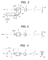
Fig. 2 is a cross-sectional view of essential
portions (a main scanning cross-sectional view) of
the laser beam source to the deflecting surface of
the light deflector of the multibeam scanning optical
system of Fig. 1 in the main scanning direction, and
Fig. 3 is a cross-sectional view of essential
portions (a sub scanning cross-sectional view) of the
laser beam source to the deflecting surface of the
light deflector of the multibeam scanning optical
system of Fig. 1 in the sub scanning direction. In
Figs. 2 and 3, the same elements as the elements
shown in Fig. 1 are given the same reference
characters.
In Figs. 2 and 3, the two laser beam sources 1a
and 1b are arranged separately from each other in the
main scanning cross section, and the two beams
emitted from the laser beam sources 1a and 1b are
converted into convergent beams by the corresponding
converting elements 2a and 2b, and thereafter enter
the beam combining prism 3. The two beams emitted
from the laser beam sources 1a and 1b are both
linearly polarized lights of which the polarization
directions are the same.
The beam emitted from the laser beam source 1a
and converted into a convergent beam by the
converting element 2a enters the beam combining prism
3 from the incidence surface 35 thereof, is reflected
by a surface 31, is further reflected by the
polarizing beam splitter surface 32 of the prism 3,
passes through a quarter wavelength plate 33 disposed
on the exit surface 36 of the prism 3, and is
converted into circularly polarized light and emerges.
The beam emitted from the laser beam source 1b
and converted into a convergent beam by the
converting element 2b passes through a half
wavelength plate 34 disposed on the incidence surface
35 of the beam combining prism 3, has its
polarization direction rotated by 90°, is transmitted
through the polarizing beam splitter surface 32 of
the beam combining prism 3, passes through the
quarter wavelength plate 33 disposed on the exit
surface 36 of the beam combining prism 3 and is
converted into circularly polarized light.
The two beams both converted into circularly
polarized lights are converged only in the sub
scanning direction by the cylindrical lens 4, and
have their beam widths limited by the aperture stop 5,
and are imaged into a focal line shape long in the
main scanning direction on or near the deflecting
surface 6a of the light deflector 6.
When the laser beam sources 1a and 1b are
arranged in the main scanning cross section, as can
be seen from Fig. 3, the two beams emitted from the
laser beam sources 1a and 1b are imaged at the same
position P in the sub scanning direction on or near
the deflecting surface 6a of the light deflector 6.
Here, consider a case where the beam emitted
from the laser beam source 1a has been parallel-moved
in the sub scanning direction.
Fig. 4 is a sub scanning cross-sectional view
when the laser beam source 1a and the converting
element 2a corresponding thereto have been moved in
the sub scanning direction (upwardly as viewed in Fig.
4) by the same amount δz1 relative to the center axis
Lx.
In Fig. 4, the convergent beam La1 having
emerged δz1 above from the center axis Lx passes
through the beam combining prism 3, is converged only
in the sub scanning direction by the cylindrical lens
4, has its beam width limited by the aperture stop 5,
and is imaged into a focal line shape on or near the
deflecting surface 6a of the light deflector 6 at a
point Q upwardly separate by δz2 in the sub scanning
direction relative to a reference point P.
Even if the beam emerging from the converting
element 2a, when it is a parallel beam, deviates in
the sub scanning direction, the imaging position in
the sub scanning direction on or near the deflecting
surface 6a of the light deflector 6 does not change,
and it can be readily understood that the beam is
always imaged at the point P.
In the present embodiment, the beam emerging
from the converting element 2a is made into a
convergent beam, whereby the convergent beam emerging
δz1 from above the center axis Lx is imaged on or
near the deflecting surface 6a of the light deflector
6 at the position Q upwardly separate by δz2 in the
sub scanning direction from the reference point P.
The beam imaged at the position Q is then imaged on
the surface to be scanned not shown, at a position
downwardly separate by a distance δz3 in the sub
scanning direction as compared with the reference
point P, by a scanning optical system, not shown.
That is, if the beam emerging from the
converting element 2a is made into a convergent beam,
the beam emerging from the converting element 2a with
the laser beam source 1a and the converting element
2a displaced by the same amount is displaced in the
sub scanning direction, whereby the imaging position
in the sub scanning direction on the surface 8 to be
scanned can be adjusted.
Specifically, design is made such that the beam
converting means 11a comprising the laser beam source
1a and the converting element 2a is moved in the sub
scanning direction (a vertical direction as viewed in
Fig. 4) by adjusting means 91, and the relative
imaging position in the sub scanning direction on the
surface 8 to be scanned is adjusted to thereby adjust
(or change) the width of the scanning line pitch in
the sub scanning direction on the surface 8 to be
scanned. While in the present embodiment, the beam
converting means 11a is moved in the scanning
direction, the beam converting means 11b or the beam
converting means 11a and the beam converting means
11b can be relatively moved in the sub scanning
direction to thereby adjust (or change) the scanning
line pitch in the sub scanning direction on the
surface 8 to be scanned.
Reference is now had to Fig. 5 to describe the
principle on which, when the beam emerging from the
converting element 2a is made into a convergent beam,
the convergent beam emerging from δz1 above the
converting element 2a is imaged on or near the
deflecting surface 6a of the light deflector 6 at the
position Q upwardly separate by the distance δz2 in
the sub scanning direction.
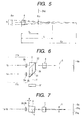
Fig. 5 is a sub scanning cross-sectional view
illustrating the principle of the adjustment of the
pitch interval in the sub scanning direction in the
multibeam scanning optical system of Fig. 1. In Fig.
5, the letter R represents the convergent beam
emerging from the converting element 2a. The
reference numeral 4 designates the cylindrical lens,
and the beam entering the cylindrical lens 4, when it
does not pass through the cylindrical lens 4, is such
a convergent beam as is imaged at a position of a
distance Sd from the cylindrical lens 4. When the
focal length of the cylindrical lens 4 in the sub
scanning cross section is defined as fs, the
convergent beam having entered the cylindrical lens 4
is imaged at a position of a distance Sk from the
cylindrical lens 4 (this position is the deflecting
surface 6a).
Here, the relation that
1Sk = 1Sd + 1fs
is established among Sd, fs and Sk.
When the beam entering the cylindrical lens 4
has entered with a deviation of a distance δz1 in the
sub scanning direction, the amount of deviation δz2
of the beam in the sub scanning direction at the
imaging point position in the sub scanning direction
is
δz2 = fs - Skfs × δz1 = SkSd × δz1
because as is apparent from Fig. 5, the relation that
δz1 fs = δz2 fs - Sk
is established.
While here, the beam entering the cylindrical
lens 4 is described as a convergent beam, it can be
readily understood from the foregoing description
that likewise in the case of a divergent beam, the
imaging point position in the sub scanning direction
can be deviated (in the case of a divergent beam, the
direction of deviation becomes opposite).
As described above, in the present embodiment,
design is made such that the beams emitted from the
laser beam sources 1a and 1b are converted into
convergent beams by the corresponding converting
elements 2a and 2b, and one 11a of the beam
converting means 11a and 11b comprised of the light
sources 1a, 1b and the converting elements 2a, 2b is
moved in the sub scanning direction (vertically as
viewed in Fig. 5) to thereby adjust the relative
imaging position in the sub scanning direction on the
surface 8 to be scanned, whereby the width of the
scanning line pitch in the sub scanning direction on
the surface 8 to be scanned is adjusted (or changed).
Therefore, as compared with the conventional
construction in which a light source unit comprised
of a plurality of light sources and a beam combining
prism or the like is rotated about the optical axis
of the optical system in a plane perpendicular to the
optical axis, it is possible to adopt a construction
in which the number of parts displaced in case of
adjustment is small and which is strong against
mechanical vibration, and there can be provided a
multibeam scanning optical system which is free of
changes in the pitch in the sub scanning direction
and copes with the requirement for a higher quality
of image.
In the present embodiment, the above-described
multibeam scanning optical system is contained in a
housing (a multibeam optical scanning apparatus).
While in the present embodiment, the f lens system
is comprised of a lens, this is not restrictive, but
the f lens system may be comprised of two or more
lenses.
[Embodiment 2]
Fig. 6 is a main scanning cross-sectional view
of the laser beam source to the deflecting surface of
the light deflector of Embodiment 2 of the multibeam
scanning optical system of the present invention.
Fig. 7 is a sub scanning cross-sectional view of the
portions of Fig. 6. In Figs. 6 and 7, the same
elements as the elements shown in Figs. 2 and 3 are
given the same reference characters.
The difference of the present embodiment from
the aforedescribed Embodiment 1 is that by the
adjusting means 91, the beam combining prism 3 is
rotated about an axis (rotary axis) Y lying in the
main scanning cross section and substantially
parallel to the surface to be scanned, to thereby
adjust the relative imaging position in the sub
scanning direction on the surface 8 to be scanned,
whereby the scanning line pitch in the sub scanning
direction on the surface 8 to be scanned is adjusted
(or changed). In the other points, the construction
and optical action of the present embodiment are
substantially similar to those of Embodiment 1,
whereby there is obtained a similar effect.
That is, in the present embodiment, design is
made such that the beam combining prism 3 is rotated
about the axis Y lying in the main scanning cross
section and substantially parallel to the surface to
be scanned to thereby adjust (or change) the relative
imaging position (scanning line pitch) of the two
beams in the sub scanning direction on the surface to
be scanned.
In the present embodiment, as shown in Fig. 7,
the beam combining prism 3 is rotated by an angle
about the axis Y. Thereby, the beam emitted from the
laser beam source 1b and converted into a convergent
beam by the converting element 2b enters the
cylindrical lens 4 while being downwardly deviated by
δzb (a negative value) in the sub scanning direction
by the refracting action of the incidence surface and
exit surface of the beam combining prism 3.
On the other hand, the beam emitted from the
light source 1a and converted into a convergent beam
by the converting element 2a enters the cylindrical
lens 4 while being upwardly deviated by δza (a
positive value) in the sub scanning direction by the
refracting action of the incidence surface and exit
surface of the beam combining prism 3 and the
reflecting action of the polarizing beam splitter
surface 32. That is, the beam converted into a
convergent beam by the converting element 2a is
downwardly refracted by the incidence surface 35 of
the beam combining prism 3. Next, it is upwardly
reflected by the surface 31 of the beam combining
prism 3. Further, it is downwardly reflected by the
polarizing beam splitter surface 32 of the beam
combining prism 3, and lastly is refracted by the
exit surface 36 of the beam combining prism 3, and
finally emerges from the beam combining prism 3 at
the same angle as that when it enters the incidence
surface 35 of the beam combining prism 3.
At this time, the beam emerging from the beam
combining prism 3 emerges while being upwardly
deviated by δza (a positive value) in the sub
scanning direction because the distance from the
surface 31 to the polarizing beam splitter surface 32
of the beam combining prism 3 is long. Finally, the
two convergent beams become deviated relative to each
other by δz1 = δzb - δza in the sub scanning direction.
This amount of deviation δz1 is varied by the angle
of rotation of the beam combining prism 3.
In the present embodiment, design is made such
that only the beam combining prism 3 is rotated about
the axis Y lying in the main scanning cross section
and substantially parallel to the surface to be
scanned, and the angle of rotation thereof is
adjusted to thereby adjust (or change) the scanning
line pitch in the sub scanning direction on the
surface 8 to be scanned.
By adopting such a construction, as compared
with the conventional construction in which a light
source unit comprised of a plurality of light sources
and a beam combining prism or the like is rotated
about the optical axis of an optical system in a
plane perpendicular to the optical axis, the part to
be displaced in case of adjustment can be only the
beam combining prism 3, and it becomes possible to
adopt a construction which is simplified in adjusting
mechanism and strong against mechanical vibration.
Further, when the beam combining prism 3 is to
be rotated as in the present embodiment, the value of
the amount of deviation δz1 of the two convergent
beams relative to the angle of rotation of the beam
combining prism 3 in the sub scanning direction is
small, in other words, the sensitivity of adjustment
is small and therefore, it becomes possible to
achieve the increased efficiency of the adjusting
work and further, it becomes possible to provide a
construction excellent in stability to environmental
fluctuations (e.g. temperature change, etc.).
While again in the present embodiment, the
beams emerging from the converting elements 2a and 2b
are described as convergent beams, it is of course
possible to obtain a similar effect even if they are
divergent beams.
[Embodiment 3]
Fig. 8 is a main scanning cross-sectional view
of the laser beam sources to the deflecting surface
of the light deflector of Embodiment 3 of the
multibeam scanning optical system of the present
invention. In Fig. 8 the same elements as the
elements shown in Fig. 2 are given the same reference
characters.
The difference of the present embodiment from
the aforedescribed Embodiment 1 or Embodiment 2 is
that the converting element 2b constituting an
element of the beam converting means 11b is disposed
while being more deviated by a predetermined amount
δx toward the beam combining prism 3 side than the
converting element 2a constituting an element of the
beam converting means 11a. In the other points, the
construction and optical action of the present
embodiment are substantially similar to those of
Embodiment 1 or Embodiment 2, whereby there is
obtained a similar effect.
That is, while in the present embodiment, the
laser beam sources 1a and 1b are disposed at the same
positions in the direction of the optical axis, the
converting element 2b is disposed while being more
deviated by a predetermined amount δx toward the beam
combining prism 3 side than the converting element 2a.
Again in the present embodiment, the beams
emerging from the converting elements 2a and 2b are
convergent beams. Considering the optical path
length along which the two beams emitted from the
laser beam sources 1a and 1b are combined by the beam
combining prism 3 via the converting elements 2a and
2b, and pass through the scanning optical system, not
shown, and arrive at the surface 8 to be scanned, the
beam emitted from the laser beam source 1b becomes
longer in the optical path length by an amount
reflected in the beam combining prism 3 than the beam
emitted from the laser beam source 1a. In this case,
if as shown, for example, in Fig. 9, the distances
from the laser beam sources 1a and 1b to the
converting elements 2a and 2b, respectively, are made
equal to each other, when the focal lengths of the
converting elements 2a and 2b are the same, the
distances to the natural converging points of the two
convergent beams become different from each other.
Specifically, the natural converging point P of
the beam emerging from the converting element 2a
deviates farther, as viewed from the laser beam
sources 1a and 1b, than the natural converging point
Q of the beam emerging from the converting element 2b.
If the distances from the principal point on the
light deflector side (the object side) of the
scanning optical system to the natural converging
points of the two beams are not made coincident with
each other, the imaging positions of the two beams in
the direction of the optical axis will not coincide
with each other and therefore, if these beams are
imaged by the scanning optical system, there will
occur the inconvenience that deviation occurs between
the imaging positions of the two beams on the surface
8 to be scanned in the direction of the optical axis.
Here, the natural converging point is a position at
which the convergent beam emerging from the
converting element 2a or 2b is imaged into a spot
shape when it does not pass through the f lens 7.
Also, when the beam emerging from the converting
element 2a or 2b is a divergent beam, the natural
converging point is the position of the virtual image
of the point at which the beam is imaged into the
spot shape.
So, in the present embodiment, the light
sources 1a and 1b are disposed at the same position
in the direction of the optical axis and also, the
converting element 2b is disposed while being more
deviated by a predetermined amount δx toward the beam
combining prism 3 side than the converting element 2a.
Thereby the distances from the principal point on the
light deflector side of the scanning optical system
to the natural converging points of the two
convergent beams are made coincident with each other,
and the two imaging positions on the surface 8 to be
scanned in the direction of the optical axis are made
coincident with each other.
While in the present embodiment, the light
sources 1a and 1b are disposed at the same position
in the direction of the optical axis and the
converting element 2b is disposed while being more
deviated by the predetermined amount δx toward the
beam combining prism 3 side than the converting
element 2a, whereby the distances from the principal
point on the light deflector side of the scanning
optical system to the natural converging points of
the respective beams are made coincident with each
other, this is not restrictive, but for example, the
converting elements 2a and 2b may be disposed at the
same position in the direction of the optical axis
and the laser beam source 1b may be disposed while
being more deviated by a predetermined amount in a
direction away from the beam combining prism 3 side
than the laser beam source 1a to thereby obtain a
similar effect. Also, the converting element 2b and
the laser beam source 1b may be disposed while being
deviated by a predetermined amount relative to the
converting element 2a and the laser beam source 1a to
thereby obtain a similar effect.
In the present embodiment, the adjustment (or
changing) of the scanning line pitch in the sub
scanning direction on the surface 8 to be scanned is
effected by an adjusting method equal to that in the
aforedescribed Embodiment 1 or Embodiment 2.
Again in Embodiment 3, the beams emerging from
the converting elements 2a and 2b are convergent
beams, but even when they are divergent beams, it is
possible to obtain a similar effect.
[Embodiment 4]
Fig. 10 is a main scanning cross-sectional view
of the laser beam source to the deflecting surface of
the light deflector of Embodiment 4 of the multibeam
scanning optical system of the present invention. In
Fig. 10, the same elements as the elements shown in
Fig. 2 are given the same reference characters.
The difference of the present embodiment from
the aforedescribed Embodiment 2 is that laser beam
sources 21a and 21b constituting the elements of beam
converting means 31a and 31b are comprised of
monolithic multibeam lasers having a plurality of
light emitting points, and by the adjusting means 92,
the monolithic multibeam lasers 21a and 21b are
rotated about the optical axis to thereby adjust (or
change) the scanning line pitch in the sub scanning
direction on the surface to be scanned. In the other
points, the construction and optical action of the
present embodiment are substantially similar to those
of Embodiment 2, whereby a similar effect is obtained.
That is, in the present embodiment, the laser
beam sources 21a and 21b are comprised of monolithic
multibeam lasers each having a plurality of light
emitting points (21a1, 21a2; 21b1, 21b2).
In the aforedescribed Embodiments 1 to 3, the
respective laser beam sources 1a and 1b use single
beam lasers each comprising a single light emitting
point (light source). By adopting such construction,
it is sufficiently possible to obtain high recording
density and a high-speed output, but hereafter,
higher recording density and a higher-speed output
are required. To meet such requirements, it becomes
necessary to increase the number of light emitting
points, because the number of revolutions of the
light deflector is limited. Here, if three or more
beams emerging from a single beam laser comprising a
single light emitting points are to be combined, a
combining mechanism therefore will become complicated
and become weak against mechanical vibration and at
the same time, the adjustment of the scanning line
pitch corresponding to each beam will become very
much complicated.
So, in the present embodiment, as described
above, the laser beam sources 21a and 21b are
comprised of monolithic multibeam lasers each having
a plurality of light emitting points (21a1, 21a2;
21b1, 21b2).
Each of the monolithic multibeam lasers 21a and
21b is disposed while being inclined at a
predetermined angle δ with respect to the main
scanning direction as shown in Fig. 11, and by
adjusting the angle δ, the intervals among the
respective scanning lines in the sub scanning
direction on the surface to be scanned are adjusted
in accordance with the recording density.
The monohithic multibeam lasers 21a and 21b are
rotated about the optical axis to thereby accurately
effect the adjustment (or changing) of the pitch
interval in the sub scanning direction, whereafter
they are fixed.
When in this state, the imaging positions of
the beams emitted from the light emitting points
(21a1, 21a2; 21b1, 21b2) on the surface to be scanned
are such as shown in Fig. 12 wherein relative
deviations are left between the imaging positions of
the light emitting points 21a1, 21a2 and the imaging
positions of the light emitting points 21b1, 21b2.
So, in the present embodiment, design is made
such that these relative deviations are adjusted (or
changed) by rotating only the beam combining prism 3
about the axis Y lying in the main scanning cross
section and substantially parallel to the surface to
be scanned by the adjusting means 91 as in the
aforedescribed Embodiment 2, for instance (the
adjusting method shown in Embodiment 1 may be used
for this adjustment of the relative deviations).
If such a construction is adopted, the
combining mechanism can intactly use the beam
combining prism shown in the aforedescribed
Embodiments 1 to 3, and it is possible to adopt a
construction which is strong against mechanical
vibration, and it becomes also possible to provide a
construction which is excellent in stability to
environmental fluctuations.
Also, if in the conventional construction
wherein the light source unit comprised of a
plurality of light sources and a beam combining prism
or the like is rotated about the optical axis of the
optical system in a plane perpendicular to the
optical axis, the relative deviations between the
imaging positions of the light emitting points 21a1,
21a2 and the imaging positions of the light emitting
points 21b1, 21b2 are adjusted, the already adjusted
imaging positions of the light emitting point 21a1
and the light emitting point 21a2, and the light
emitting point 21b1 and the light emitting point 21b2
(the pitch interval in the sub scanning direction)
will change and the necessity of adjusting them again
will occur.
In contrast, in the present embodiment, if the
adjusting method as described above is adopted, even
if the relative deviations between the imaging
positions of the light emitting points 21a1, 21a2 and
the imaging positions of the light emitting points
21b1, 21b2 are adjusted, the already adjusted imaging
positions of the light emitting point 21a1 and the
light emitting point 21a2, and the light emitting
point 21b1 and the light emitting point 21b2 (the
pitch interval in the sub scanning direction) will
not change, and this also leads to the effect that
the simplification of the adjusting step can be
achieved.
While in the present embodiment, both of the
two laser beam sources 21a and 21b are comprised of
monolithic multibeam lasers, one of them may be
comprised of a monolithic multibeam laser.
[Image Forming Apparatus]
Fig. 13 is a cross-sectional view of essential
portions in the sub scanning direction showing an
embodiment of an image forming apparatus (an
electrophotographic printer) using the multibeam
scanning optical system (multibeam optical scanning
apparatus) according to any one of the aforedescribed
Embodiments 1 to 4. In Fig. 13, the reference
numeral 104 designates the image forming apparatus.
Code data Dc is inputted from an external device 117
such as a personal computer to the image forming
apparatus 104. This code data Dc is converted into
image data (dot data) Di by a printer controller 111
in the apparatus. This image data Di is inputted to
the optical scanning unit 100 shown in any one of
Embodiments 1 to 4. A light beam (beam) 103
modulated in conformity with the image data Di is
emitted from the optical scanning unit (multibeam
scanning optical system) 100, and the photosensitive
surface of a photosensitive drum 101 is scanned in
the main scanning direction by the light beam 103.
The photosensitive drum 101 which is an
electrostatic latent image bearing member (a
photosensitive member) is clockwisely rotated by a
motor 115. With this rotation, the photosensitive
surface of the photosensitive drum 101 moves relative
to the light beam 103 in the sub scanning direction
orthogonal to the main scanning direction. A
charging roller 102 for uniformly charging the
surface of the photosensitive drum 101 is provided
above the photosensitive drum 101 so as to contact
with the surface of the latter. The light beam 103
scanned by the optical scanning unit 100 is designed
to be applied to the surface of the photosensitive
drum 101 charged by the charging roller 102.
As previously described, the light beam 103 is
modulated on the basis of the image data Di, and this
light beam 103 is applied to the surface of the
photosensitive drum 101 to thereby form an
electrostatic latent image thereon. This
electrostatic latent image is developed as a toner
image by a developing device 107 disposed downstream
of the applied position of the light beam 103 with
respect to the direction of rotation of the
photosensitive drum 101 so as to abut against the
photosensitive drum 101.
The toner image developed by the developing
device 107 is transferred onto a sheet 112 which is a
transfer material by a transferring roller
(transferring device) 108 disposed below the
photosensitive drum 101 so as to be opposed to the
photosensitive drum 101. The sheet 112 is contained
in a sheet cassette 109 disposed forwardly (at the
right as viewed in Fig. 13) of the photosensitive
drum 101, and it can also be manually fed. A sheet
feeding roller 110 is disposed at one end of the
sheet cassette 109, and feeds the sheets 112 in the
sheet cassette 109 to a conveying path.
The sheet 112 onto which the unfixed toner
image has been transferred in the manner described
above is further conveyed to a fixing device disposed
rearwardly (at the left as viewed in Fig. 13) of the
photosensitive drum 101. The fixing device is
comprised of a fixing roller 113 having a fixing
heater (not shown) therein and a pressure roller 114
disposed so as to be in pressure contact with the
fixing roller 113, and pressurizes and heats the
sheet 112 conveyed thereto from the transferring
portion by the pressure contact portion between the
fixing roller 113 and the pressure roller 114 to
thereby fix the unfixed toner image on the sheet 112.
Further, delivery rollers 116 are disposed rearwardly
of the fixing roller 113, and delivers the fixed
sheet 112 out of the image forming apparatus.
Although not shown in Fig. 13, the printer
controller 111 effects not only the conversion of the
aforedescribed data, but also the control of various
portions including the motor 115 in the image forming
apparatus and a polygon motor, etc. in the optical
scanning unit 100.
According to the present invention, there can
be achieved a multibeam scanning optical system in
which, as previously described, the relative position
of a plurality of beams in the sub scanning direction
is adjusted to thereby adjust (or change) the
relative imaging position in the sub scanning
direction on the surface to be scanned, whereby which
is strong against mechanical vibration or the like
and suffers little from pitch fluctuation and is
excellent in environmental stability, and an image
forming apparatus using the same.
Further, according to the present invention,
there can be achieved a multibeam scanning optical
system in which, as previously described, a laser
beam source is comprised of a monolithic multibeam
laser having a plurality of light emitting points to
thereby cope with requirements for a higher speed and
a higher quality of image, and an image forming
apparatus using the same.