EP1247959A2 - Piston control mechanism of reciprocating internal combustion engine of variable compression ratio type - Google Patents
Piston control mechanism of reciprocating internal combustion engine of variable compression ratio type Download PDFInfo
- Publication number
- EP1247959A2 EP1247959A2 EP02005860A EP02005860A EP1247959A2 EP 1247959 A2 EP1247959 A2 EP 1247959A2 EP 02005860 A EP02005860 A EP 02005860A EP 02005860 A EP02005860 A EP 02005860A EP 1247959 A2 EP1247959 A2 EP 1247959A2
- Authority
- EP
- European Patent Office
- Prior art keywords
- piston
- link
- control
- axis
- crankshaft
- Prior art date
- Legal status (The legal status is an assumption and is not a legal conclusion. Google has not performed a legal analysis and makes no representation as to the accuracy of the status listed.)
- Withdrawn
Links
- 230000006835 compression Effects 0.000 title claims abstract description 46
- 238000007906 compression Methods 0.000 title claims abstract description 46
- 238000002485 combustion reaction Methods 0.000 title claims abstract description 23
- 238000005452 bending Methods 0.000 description 20
- 230000005489 elastic deformation Effects 0.000 description 13
- 238000006073 displacement reaction Methods 0.000 description 7
- 230000001965 increasing effect Effects 0.000 description 3
- 230000007935 neutral effect Effects 0.000 description 3
- 239000000446 fuel Substances 0.000 description 2
- 238000010276 construction Methods 0.000 description 1
- 230000001939 inductive effect Effects 0.000 description 1
- 230000004048 modification Effects 0.000 description 1
- 238000012986 modification Methods 0.000 description 1
- 238000005381 potential energy Methods 0.000 description 1
- 230000001105 regulatory effect Effects 0.000 description 1
- 239000007787 solid Substances 0.000 description 1
Images




Classifications
-
- F—MECHANICAL ENGINEERING; LIGHTING; HEATING; WEAPONS; BLASTING
- F02—COMBUSTION ENGINES; HOT-GAS OR COMBUSTION-PRODUCT ENGINE PLANTS
- F02B—INTERNAL-COMBUSTION PISTON ENGINES; COMBUSTION ENGINES IN GENERAL
- F02B75/00—Other engines
- F02B75/04—Engines with variable distances between pistons at top dead-centre positions and cylinder heads
- F02B75/048—Engines with variable distances between pistons at top dead-centre positions and cylinder heads by means of a variable crank stroke length
-
- F—MECHANICAL ENGINEERING; LIGHTING; HEATING; WEAPONS; BLASTING
- F02—COMBUSTION ENGINES; HOT-GAS OR COMBUSTION-PRODUCT ENGINE PLANTS
- F02B—INTERNAL-COMBUSTION PISTON ENGINES; COMBUSTION ENGINES IN GENERAL
- F02B75/00—Other engines
- F02B75/04—Engines with variable distances between pistons at top dead-centre positions and cylinder heads
- F02B75/045—Engines with variable distances between pistons at top dead-centre positions and cylinder heads by means of a variable connecting rod length
Definitions
- the present invention relates in general to reciprocating internal combustion engines of a variable compression ratio type that is capable of varying a compression ratio under operation thereof and more particularly to the reciprocating internal combustion engines of a multi-link type wherein each piston is connected to a crankshaft through a plurality of links. More specifically, the present invention is concerned with a piston control mechanism of such internal combustion engines.
- variable compression ratio type that is capable of varying a compression ratio of the engine in accordance with operation condition of the same.
- One of such engines is shown in Laid-Open Japanese Patent Application (Tokkai) 2000-73804.
- the engine of the publication employs a piston control mechanism wherein each piston is connected to a crankshaft through a plurality of links.
- crankshaft 101 having crank pins 102.
- a lower link (floating lever) 103 To each crank pin 102, there is pivotally connected a lower link (floating lever) 103 at a middle portion thereof.
- a lower link 103 To one end of lower link 103, there is pivotally connected a lower end of an upper link 106 through a first connecting pin 110.
- An upper end of the upper link 106 is pivotally connected to a piston 104 through a piston pin 105.
- To the other end of lower link 103 there is pivotally connected a lower end of a control link 107 through a second connecting pin 111.
- An upper end of control link 107 is pivotally connected to an eccentric pin 109 of a control crankshaft 108.
- control link 107 are formed with respective cylindrical bearing bores which pivotally receive second connecting pin 111 and eccentric pin 109 respectively.
- control crankshaft 108 is turned in accordance with operation condition of the engine, causing control link 107 to vary and set pivoting movement of lower link 103 thereby varying or setting a stroke of the piston 104.
- the compression ratio of the engine is varied in accordance with the engine operation condition.
- control link 107 In the piston control mechanism as mentioned hereinabove, based on both an upward inertial load applied to piston 104 when piston 104 moves upward and a downward load applied to the same when combustion takes place, a certain load is inevitably applied to control link 107 through upper link 106 and lower link 103.
- control links like the control link 107 of which both ends are formed with cylindrical bearing bores it is known that an elastic deformation appearing on control link 107 when a tensile load is applied thereto is greater than that appearing when a compression load is applied thereto. That is, variation of effective length of control link 107 in case of receiving the tensile load is larger than that in case of receiving the compression load.
- control link 107 in case of the compression load, only a shaft portion proper of control link 107 defined between the two cylindrical bearing bores is subjected to an elastic deformation, while, in case of tensile load, the entire length of control link 107 including the two thinner cylindrical bearing bores is subjected to the elastic deformation inducing the increase in elastic deformation degree.
- an object of the present invention is to provide a piston control mechanism of reciprocating internal combustion engine, which is free of the above-mentioned undesired piston displacement.
- Another object of the present invention is to provide a piston control mechanism of reciprocating internal combustion engine of variable compression ratio type, which can assuredly avoid interference between a piston and intake and exhaust valves without sacrificing engine performance, that is, without narrowing a range in which the engine compression ratio is variable.
- Still another object of the present invention is to provide a piston control mechanism of reciprocating internal combustion engine of variable compression ratio type, which is compact in size and exhibits a high cost performance.
- a piston control mechanism of an internal combustion engine including a piston slidably disposed in a piston cylinder and a crankshaft converting a reciprocation movement of the piston to a rotation movement
- the piston control mechanism comprising a lower link rotatably disposed on a crank pin of the crankshaft; an upper link having one end pivotally connected to the lower link and the other end pivotally connected to the piston; a control link having one end pivotally connected to the lower link; and a position changing mechanism which changes a supporting axis about which the other end of the control link turns, wherein when the piston comes up to a top dead center, a compression load is applied to the control link in an axial direction of the control link in accordance with an upward inertial load of the piston.
- a piston control mechanism of an internal combustion engine including a piston slidably disposed in a piston cylinder and a crankshaft converting a reciprocation movement of the piston to a rotation movement
- the piston control mechanism comprising a lower link rotatably disposed on a crank pin of the crankshaft; an upper link having one end pivotally connected to the lower link and the other end pivotally connected to the piston; a control link having one end pivotally connected to the lower link; and a position changing mechanism including a control crankshaft which extends in parallel with the crankshaft and rotates about a given axis, the control crankshaft including a main shaft portion which is rotatable about the given axis and an eccentric pin which is radially raised from the main shaft portion, the eccentric pin being received in a cylindrical bearing bore formed in the other end of the control link, wherein when the piston comes up to a top dead center, a rotation direction of an upper link center line relative to a first direction
- a piston control mechanism of a first embodiment of the present invention which is applied to a reciprocating internal combustion engine of variable compression ratio type.
- the piston control mechanism 100A of the first embodiment comprises a lower link 11 which is rotatably disposed on a crank pin 2 of a crankshaft 1 of an associated internal combustion engine at a center opening thereof.
- a center axis of crank pin 2 is denoted by reference P6.
- the lower link 11 is shaped generally triangle.
- An upper link 13 is pivotally connected at a lower end to lower link 11 through a first connecting pin 12 and pivotally connected at an upper end to a piston 3 through a piston pin 4.
- a center axis of first connecting pin 12 is denoted by reference P2 and a center axis of piston pin 4 is denoted by reference P1.
- a control link 15 is pivotally connected at an upper end to lower link 11 through a second connecting pin 14 and pivotally connected at a lower end to a body of the engine trough a position changing mechanism 16.
- a center axis of second connecting pin 14 is denoted by reference P3.
- position changing mechanism 16 is constructed to change a supporting axis P4 about which the lower end of control link 15 turns. Thus, the degree of freedom of lower link 11 is controlled.
- piston 3 is slidably received in a cylinder 6 defined in a cylinder block 5.
- a piston head 3a of piston 3 is formed with a recess that constitutes part of a combustion chamber.
- the position changing mechanism 16 comprises a control crankshaft 17 which substantially extends in parallel with crankshaft 1 and an electric actuator which rotates control crankshaft 17 about its center axis P5 in accordance with an operation condition of the engine.
- control crankshaft 17 comprises a main shaft portion 18 which rotates about the center axis P5, paired crank arms 20 which extend radially outward from the main shaft portion 18 and an eccentric pin 19 which is held between the paired crank arms 20 at a position eccentric to main shaft portion 18.
- Eccentric pin 19 is of a cylindrical solid member of which center axis P4 is the supporting axis P4 of control link 15.
- the cylindrical eccentric pin 19 is received in a cylindrical bearing bore 23 formed in a lower end of control link 15. (It is to be noted that Figs. 6A and 6B (and Figs. 7A to 8B) are exaggeratedly illustrated.)
- Control link 15 is formed at an upper end with a cylindrical bearing bore 21 which rotatably receives second connecting pin 14.
- the center axis P4 of the eccentric pin 19 (viz., supporting axis P4 of control link 15) is eccentric to the center axis P5 of main shaft portion 18 of control crankshaft 17.
- lower link 11 and control link 15 are constructed to have a split structure.
- control crankshaft 17 (see Fig. 1) is turned by the electric actuator about its center axis P5 in accordance with the engine operation condition, the lower end of control link 15 is subjected to position change and thus behavior of lower link 11 changes thereby to change the stroke of piston 3, resulting in that the compression ratio of the engine is varied.
- Figs. 3A, 3B and 3C schematically show variation of elastic deformation of control link 15 that appears when a load is applied thereto in different directions.
- These drawings respectively show a compressed condition wherein control link 15 is applied with a compression load, a neutral condition wherein control link 15 has no load applied thereto and an extended condition wherein control link 15 is applied with a tensile load.
- control link 15 and deformation of the same are illustrated exaggeratingly.
- control link 15 is formed at an upper boss portion (viz., first boss portion) 22 with the cylindrical bearing bore 21 through which second connecting pin 14 passes, and at a lower boss portion (viz., second boss portion) 24 with the cylindrical bearing bore 23 through which eccentric pin 19 passes.
- control link 15 If the distance between respective axes of pins 14 and 19 that pass through bores 21 and 23 of control link 15 is assumed as an effective length of control link 15, the effective length has the following tendency that depends on a direction in which a load is applied to control link 15.
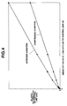
- a difference between effective length D3 of link 15 in the extended condition and effective length D1 of link 15 in neutral condition is greater than that between effective length D2 of link 15 in the compressed condition and effective length D1 of link in neutral condition.
- a downward load F2 applied to control link 15 caused by an upward inertial load F1 of piston 3 through upper link 13 and lower link 11 is adjusted to operate in a direction coincident with an imaginary line that extends through both center axis P3 of second connecting pin 14 and supporting axis P4 of control link 15 (viz., center axis P4 of eccentric pin 19. That is, piston control mechanism 100A of the first embodiment is so arranged that upon piston 3 reaching the top dead center (TDC), control link 15 is just applied with the compression load.
- a rotation direction ⁇ 1 of upper link center line 13A relative to first direction line H1 is equal to a rotation direction ⁇ 2 of control link center line 15A relative to second direction line H2.
- control link 15 when piston 3 comes up to the top dead center (TDC), control link 15 is applied with a compression load and thus, the elastic deformation of control link 15 is considerably reduced.
- TDC top dead center
- This is very advantageous when piston comes up to the top dead center (TDC) on exhaust stroke. Accordingly, the above-mentioned undesirable upward displacement of piston 3 at the top dead center on exhaust stroke is suppressed, and thus, the possibility of undesirable contact of piston crown 3a with the intake and exhaust valves is suppressed. With this advantageous operation, there is no need of narrowing a range in which the engine compression ratio is varied, and thus, engine performance can be improved.
- control link 15 is not just a deformation but an elastic deformation that has an elastic energy as a potential energy. It is thought that, under operation of engine, part of energy produced as a result of fuel combustion in combustion chamber is stored in the engine body as the elastic energy, and when piston 3 comes down while reducing the load, the stored energy is used for assisting rotation of crankshaft 1.
- control crankshaft 17 elastic deformation of control crankshaft 17 will be described with reference to Figs. 5 to 9B. It is to be noted that parts shown in these drawings are illustrated exaggeratingly for ease of understanding.
- control crankshaft 17 in case wherein the load is directed perpendicular to a third direction line H3 which perpendicularly extends across both center axis P5 of main shaft portion 18 and center axis P4 of eccentric pin 19, the bending deformation of control crankshaft 17 exhibits an intermediate value as is indicated by the characteristic line L-3 of Fig. 5.
- control crankshaft 17 directly causes the undesired displacement of piston 3 from a proper position.
- piston 3 shows a marked displacement at the top dead center (TDC) on exhaust stroke, which tends to increase the possibility of inducting the undesired contact of piston crown 3a with the intake and exhaust valves. Since, in a higher compression ratio condition as shown in Fig. 1, the top dead center (TDC) of piston 3 is positioned higher than that in a lower compression ratio condition as shown in Fig. 2, such undesired possibility is increased.
- a so-called eccentric angle ⁇ H defined between third direction line H3 (see Fig. 8B) and control link center line 15A at the top dead center of piston 3 in the higher compression ratio condition (Fig. 1) is set smaller than an eccentric angle ⁇ L defined in the lower compression ratio condition (Fig. 2).
- center axis P2 of first connecting pin 12 and center axis P3 of second connecting pin 14 are positioned at opposite sides with respect to an imaginary plane B that includes center axis P6 of crank pin 2 of crankshaft 1 and is parallel with an axis of a piston cylinder 6 of the engine, and supporting axis P4 of control link 15 is positioned below center axis P3 of second connecting pin 14.
- control crankshaft 17 whose eccentric pin 19 passes through the lower end of control crankshaft 15 can be located in an obliquely lower zone of crankshaft 1 in cylinder block 5, which usually offers a larger space.
- control crankshaft 17 and its associated parts can be compactly and readily installed in cylinder block 5 without changing the shape of the same.
- FIG. 10 there is shown a piston control mechanism 100B of a second embodiment of the present invention.
- center axis P2 of first connecting pin 12 and center axis P3 of second connecting pin 14 are positioned at the same side with respect to the imaginary plane B that includes center axis P6 of crank pin 2 of crankshaft 1 and is parallel with the axis of cylinder 6 of the engine, and supporting axis P4 of control link 15 is positioned above center axis P3 of second connecting pin 14. That is, control link 15 extends diagonally upward from lower link 11, which causes positioning of control crankshaft 17 above crankshaft 1.
- the second embodiment 100B is somewhat poor in layout.
- a rotation direction ⁇ 1 of upper link center line 13A relative to first direction line H1 is equal to a rotation direction ⁇ 2 of control link center line 15A relative to second direction line H2. Accordingly, when piston 3 comes up to dead top center on exhaust stroke, a load F2 applied to control link 15 functions to compress the same and thus bending deformation of control crankshaft 17 is minimized thereby suppressing or at least minimizing undesired upward displacement of piston 3 at the top dead center. Thus, possibility of undesirable contact of piston crown 3a with the intake and exhaust valves is suppressed.
- FIG. 11 there is shown a piston control mechanism 100C of a third embodiment of the present invention.
Landscapes
- Engineering & Computer Science (AREA)
- Chemical & Material Sciences (AREA)
- Combustion & Propulsion (AREA)
- Mechanical Engineering (AREA)
- General Engineering & Computer Science (AREA)
- Output Control And Ontrol Of Special Type Engine (AREA)
- Shafts, Cranks, Connecting Bars, And Related Bearings (AREA)
Abstract
Description
- The present invention relates in general to reciprocating internal combustion engines of a variable compression ratio type that is capable of varying a compression ratio under operation thereof and more particularly to the reciprocating internal combustion engines of a multi-link type wherein each piston is connected to a crankshaft through a plurality of links. More specifically, the present invention is concerned with a piston control mechanism of such internal combustion engines.
- In the field of reciprocating internal combustion engines, there has been proposed a variable compression ratio type that is capable of varying a compression ratio of the engine in accordance with operation condition of the same. One of such engines is shown in Laid-Open Japanese Patent Application (Tokkai) 2000-73804. The engine of the publication employs a piston control mechanism wherein each piston is connected to a crankshaft through a plurality of links.
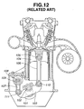
- For ease of understanding of the present invention, the piston control mechanism of the publication will be briefly described with reference to Fig. 12 of the accompanying drawings.
- In the drawing, denoted by
numeral 101 is a crankshaft havingcrank pins 102. To eachcrank pin 102, there is pivotally connected a lower link (floating lever) 103 at a middle portion thereof. To one end oflower link 103, there is pivotally connected a lower end of anupper link 106 through a first connectingpin 110. An upper end of theupper link 106 is pivotally connected to a piston 104 through apiston pin 105. To the other end oflower link 103, there is pivotally connected a lower end of acontrol link 107 through a second connectingpin 111. An upper end ofcontrol link 107 is pivotally connected to aneccentric pin 109 of acontrol crankshaft 108. More specifically, the lower and upper ends ofcontrol link 107 are formed with respective cylindrical bearing bores which pivotally receive second connectingpin 111 andeccentric pin 109 respectively. Under operation of the engine,control crankshaft 108 is turned in accordance with operation condition of the engine, causingcontrol link 107 to vary and set pivoting movement oflower link 103 thereby varying or setting a stroke of the piston 104. With this operation, the compression ratio of the engine is varied in accordance with the engine operation condition. - In the piston control mechanism as mentioned hereinabove, based on both an upward inertial load applied to piston 104 when piston 104 moves upward and a downward load applied to the same when combustion takes place, a certain load is inevitably applied to control
link 107 throughupper link 106 andlower link 103. In control links like thecontrol link 107 of which both ends are formed with cylindrical bearing bores, it is known that an elastic deformation appearing oncontrol link 107 when a tensile load is applied thereto is greater than that appearing when a compression load is applied thereto. That is, variation of effective length ofcontrol link 107 in case of receiving the tensile load is larger than that in case of receiving the compression load. That is, in case of the compression load, only a shaft portion proper ofcontrol link 107 defined between the two cylindrical bearing bores is subjected to an elastic deformation, while, in case of tensile load, the entire length ofcontrol link 107 including the two thinner cylindrical bearing bores is subjected to the elastic deformation inducing the increase in elastic deformation degree. - When piston 104 comes up to a top dead center (TDC) on exhaust stroke, upward inertial load of piston 104 brings the crown of the same into a position closest to intake and exhaust valves. Furthermore, when, due to valve overlapping or the like, intake and exhaust valves are still open partially at such top dead center (TDC), the piston crown becomes much closer to the intake and exhaust valves. Thus, when, with piston 104 taking the top dead center (TDC) on exhaust stroke, a certain tensile load is applied to control
link 107 based on the upward inertial load of piston 104, the elastic deformation ofcontrol link 107 becomes remarkable causing piston 104 to be displaced from a proper position, which tends to deteriorate engine performance. Furthermore, if the displacement of piston 104 becomes remarkably large, undesirable interference between piston 104 and intake and exhaust valves may occur. - Accordingly, an object of the present invention is to provide a piston control mechanism of reciprocating internal combustion engine, which is free of the above-mentioned undesired piston displacement.
- Another object of the present invention is to provide a piston control mechanism of reciprocating internal combustion engine of variable compression ratio type, which can assuredly avoid interference between a piston and intake and exhaust valves without sacrificing engine performance, that is, without narrowing a range in which the engine compression ratio is variable.
- Still another object of the present invention is to provide a piston control mechanism of reciprocating internal combustion engine of variable compression ratio type, which is compact in size and exhibits a high cost performance.
- According to a first aspect of the present invention, there is provided a piston control mechanism of an internal combustion engine, the engine including a piston slidably disposed in a piston cylinder and a crankshaft converting a reciprocation movement of the piston to a rotation movement, the piston control mechanism comprising a lower link rotatably disposed on a crank pin of the crankshaft; an upper link having one end pivotally connected to the lower link and the other end pivotally connected to the piston; a control link having one end pivotally connected to the lower link; and a position changing mechanism which changes a supporting axis about which the other end of the control link turns, wherein when the piston comes up to a top dead center, a compression load is applied to the control link in an axial direction of the control link in accordance with an upward inertial load of the piston.
- According to a second aspect of the present invention, there is provided a piston control mechanism of an internal combustion engine, the engine including a piston slidably disposed in a piston cylinder and a crankshaft converting a reciprocation movement of the piston to a rotation movement, the piston control mechanism comprising a lower link rotatably disposed on a crank pin of the crankshaft; an upper link having one end pivotally connected to the lower link and the other end pivotally connected to the piston; a control link having one end pivotally connected to the lower link; and a position changing mechanism including a control crankshaft which extends in parallel with the crankshaft and rotates about a given axis, the control crankshaft including a main shaft portion which is rotatable about the given axis and an eccentric pin which is radially raised from the main shaft portion, the eccentric pin being received in a cylindrical bearing bore formed in the other end of the control link, wherein when the piston comes up to a top dead center, a rotation direction of an upper link center line relative to a first direction line is equal to a rotation direction of a control link center line relative to a second direction line, the upper link center line being an imaginary line which perpendicularly crosses both a first pivot axis between the piston and the upper link and a second pivot axis between the upper link and the lower link, the control link center line being an imaginary line which perpendicularly crosses both a third pivot axis between the lower link and the control link and the supporting axis, the first direction line being an imaginary line which perpendicularly crosses both the second pivot axis and a center axis of the crank pin, and the second direction line being an imaginary line which perpendicularly crosses both the third pivot axis and the center axis of the crank pin.
-
- Fig. 1 is a sectional view of an internal combustion engine having a piston control mechanism of a first embodiment, showing a piston assuming a top dead center (TDC) under a higher compression ratio condition;
- Fig. 2 is a view similar to Fig. 1, but showing the piston assuming the top dead center (TDC) under a lower compression ratio condition;
- Figs. 3A, 3B and 3C are illustrations of a control link, showing variation of elastic deformation depending on loading direction;
- Fig. 4 is a graph showing a relation between a load applied to a control link and an elastic deformation appearing on the control link;
- Fig. 5 is a graph showing a relation between a load inputted to a control crankshaft and a bending deformation appearing on the control crankshaft;
- Figs. 6A and 6B are front and sectional views of a unit including the control crankshaft and the control link, showing the bending deformation of the control crankshaft appearing when a load is applied thereto in a first direction;
- Figs. 7A and 7B are views similar to Figs. 6A and 6B, but showing the bending deformation of the control crankshaft appearing when a load is applied thereto in a second direction;
- Figs. 8A and 8B are views similar to Figs. 6A and 6B, but showing the bending deformation of the control crankshaft appearing when a load is applied thereto in a third direction;
- Figs. 9A and 9B are partial front views of the unit including the control crankshaft and the control link, showing difference of bending deformation of control crankshaft depending on a direction in which a load is applied;
- Fig. 10 is a view similar to Fig. 1, but showing a second embodiment of the present invention;
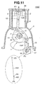
- Fig. 11 is a view similar to Fig. 1, but showing a third embodiment of the present invention; and
- Fig. 12 is a sectional view of an internal combustion engine of known variable compression ratio type.
-
- In the following, various embodiments of the present invention will be described in detail with reference to the accompanying drawings.
- For ease of understanding, various directional terms, such as, right, left, upper, lower, rightward, etc., are contained in the description. However, such terms are to be understood with respect to only drawing or drawings on which corresponding part or portion is illustrated.
- Furthermore, for simplification of description, throughout the description, substantially same parts and constructions are denoted by the same numerals and repeated explanation of them will be omitted.
- Referring to Figs. 1 to 9A and 9B, particularly Figs. 1 and 2, there is shown a piston control mechanism of a first embodiment of the present invention, which is applied to a reciprocating internal combustion engine of variable compression ratio type.
- As is seen from Fig. 1, the
piston control mechanism 100A of the first embodiment comprises alower link 11 which is rotatably disposed on acrank pin 2 of acrankshaft 1 of an associated internal combustion engine at a center opening thereof. A center axis ofcrank pin 2 is denoted by reference P6. Thelower link 11 is shaped generally triangle. Anupper link 13 is pivotally connected at a lower end tolower link 11 through a first connectingpin 12 and pivotally connected at an upper end to apiston 3 through apiston pin 4. A center axis of first connectingpin 12 is denoted by reference P2 and a center axis ofpiston pin 4 is denoted by reference P1. Acontrol link 15 is pivotally connected at an upper end tolower link 11 through asecond connecting pin 14 and pivotally connected at a lower end to a body of the engine trough aposition changing mechanism 16. A center axis of second connectingpin 14 is denoted by reference P3. As will be described in detail hereinafter,position changing mechanism 16 is constructed to change a supporting axis P4 about which the lower end of control link 15 turns. Thus, the degree of freedom oflower link 11 is controlled. - As shown,
piston 3 is slidably received in acylinder 6 defined in acylinder block 5. Apiston head 3a ofpiston 3 is formed with a recess that constitutes part of a combustion chamber. - The
position changing mechanism 16 comprises acontrol crankshaft 17 which substantially extends in parallel withcrankshaft 1 and an electric actuator which rotatescontrol crankshaft 17 about its center axis P5 in accordance with an operation condition of the engine. - As is seen from Figs. 6A and 6B,
control crankshaft 17 comprises amain shaft portion 18 which rotates about the center axis P5, paired crankarms 20 which extend radially outward from themain shaft portion 18 and aneccentric pin 19 which is held between the paired crankarms 20 at a position eccentric tomain shaft portion 18.Eccentric pin 19 is of a cylindrical solid member of which center axis P4 is the supporting axis P4 ofcontrol link 15. The cylindricaleccentric pin 19 is received in a cylindrical bearing bore 23 formed in a lower end ofcontrol link 15. (It is to be noted that Figs. 6A and 6B (and Figs. 7A to 8B) are exaggeratedly illustrated.)Control link 15 is formed at an upper end with a cylindrical bearing bore 21 which rotatably receives second connectingpin 14. - As is seen from Fig. 6B, the center axis P4 of the eccentric pin 19 (viz., supporting axis P4 of control link 15) is eccentric to the center axis P5 of
main shaft portion 18 ofcontrol crankshaft 17. - For achieving easy mounting onto crank
pin 2 andeccentric pin 19,lower link 11 and control link 15 are constructed to have a split structure. - When, in operation, control crankshaft 17 (see Fig. 1) is turned by the electric actuator about its center axis P5 in accordance with the engine operation condition, the lower end of
control link 15 is subjected to position change and thus behavior oflower link 11 changes thereby to change the stroke ofpiston 3, resulting in that the compression ratio of the engine is varied. - Figs. 3A, 3B and 3C schematically show variation of elastic deformation of control link 15 that appears when a load is applied thereto in different directions. These drawings respectively show a compressed condition wherein control link 15 is applied with a compression load, a neutral condition wherein control link 15 has no load applied thereto and an extended condition wherein control link 15 is applied with a tensile load. For ease of understanding,
control link 15 and deformation of the same are illustrated exaggeratingly. - As is seen from these drawings, control link 15 is formed at an upper boss portion (viz., first boss portion) 22 with the cylindrical bearing bore 21 through which second connecting
pin 14 passes, and at a lower boss portion (viz., second boss portion) 24 with the cylindrical bearing bore 23 through whicheccentric pin 19 passes. - If the distance between respective axes of
pins bores control link 15 is assumed as an effective length ofcontrol link 15, the effective length has the following tendency that depends on a direction in which a load is applied to controllink 15. - That is, as is seen from the drawings, a difference between effective length D3 of
link 15 in the extended condition and effective length D1 oflink 15 in neutral condition is greater than that between effective length D2 oflink 15 in the compressed condition and effective length D1 of link in neutral condition. - The reasons of this phenomenon may be as follows.
- That is, in case of applying a compression load to control link 15 (viz., Fig. 3A), only a
main shaft portion 25 oflink 15 is compressed leaving upper andlower boss portions main shaft portion 25 but also upper andlower boss portions link 15 are extended axially outward, and thus, the above-mentioned phenomenon takes place. - As is known, when, under operation of the engine,
piston 3 comes up to a top dead center (TDC) particularly on exhaust stroke, a remarked upward inertia load F1 (see Fig. 1) is applied topiston 3. This inertia load tends to bringpiston 3 to a position closest to the intake and exhaust valves. Accordingly, when, due to valve overlapping or the like, the intake and exhaust valve are still open partially at such top dead center (TDC),piston 3 becomes much closer to the intake and exhaust valves increasing a possibility of undesirable contact of piston crown with the intake and exhaust valves. - In order to assuredly avoid such undesired contact, the following measures are practically employed in the
first embodiment 100A of the present invention. - That is, as is seen from Fig. 1, at the time when
piston 3 comes up to the top dead center (TDC), a downward load F2 applied to controllink 15 caused by an upward inertial load F1 ofpiston 3 throughupper link 13 andlower link 11 is adjusted to operate in a direction coincident with an imaginary line that extends through both center axis P3 of second connectingpin 14 and supporting axis P4 of control link 15 (viz., center axis P4 ofeccentric pin 19. That is,piston control mechanism 100A of the first embodiment is so arranged that uponpiston 3 reaching the top dead center (TDC), control link 15 is just applied with the compression load. - The measures of the
first embodiment 100A will be much clearly understood from the following description. - Let us call an imaginary line perpendicularly crossing both center axis P1 of
piston pin 4 and center axis P2 of first connectingpin 12 as an upperlink center line 13A, an imaginary line perpendicularly crossing both center axis P3 of second connectingpin 14 and supporting axis P4 of control link 15 (viz., center axis P4 of eccentric pin 19) as a controllink center line 15A, an imaginary line perpendicularly crossing both center axis P2 of first connectingpin 12 and center axis P6 ofcrank pin 2 as a first direction line H1 and an imaginary line perpendicularly crossing both center axis P3 of second connectingpin 14 and center axis P6 ofcrank pin 2 as a second direction line H2. As shown, in thefirst embodiment 100A, whenpiston 3 is at the top dead center (TDC), a rotation direction α1 of upperlink center line 13A relative to first direction line H1 is equal to a rotation direction α2 of controllink center line 15A relative to second direction line H2. - When an upward load F3 is applied to
lower link 11 along upperlink center line 13A fromupper link 13 based on upward inertial load F1,lower link 11 is applied with a torque about center axis P6 ofcrank pin 2 in the same direction as direction α1. Since direction α2 is set equal to direction α1, a load applied to controllink 15 according to the torque functions to compresscontrol link 15, that is, to applycontrol link 15 with a compression load. It is to be noted that if the rotation direction of controllink center line 15A relative to second direction line H2 is opposite to the above-mentioned direction α1, the load would function to extendcontrol link 15, that is, to applycontrol link 15 with a tensile load, which is not preferable. - As is understood from the above description, in the
first embodiment 100A, whenpiston 3 comes up to the top dead center (TDC), control link 15 is applied with a compression load and thus, the elastic deformation ofcontrol link 15 is considerably reduced. This is very advantageous when piston comes up to the top dead center (TDC) on exhaust stroke. Accordingly, the above-mentioned undesirable upward displacement ofpiston 3 at the top dead center on exhaust stroke is suppressed, and thus, the possibility of undesirable contact ofpiston crown 3a with the intake and exhaust valves is suppressed. With this advantageous operation, there is no need of narrowing a range in which the engine compression ratio is varied, and thus, engine performance can be improved. - When now
piston 3 is at the top dead center (TDC) on compression stroke wherein a downward load is applied topiston 3 due to the fuel combustion in combustion chamber, the load applied to the control link 15 functions to extend the same, that is, to apply the same with a tensile load. Thus, the elastic deformation ofcontrol link 15 becomes relatively large. However, since, in the compression stroke, both the intake and exhaust valves are kept closed and the load applied topiston 3 is directed downward, there is no possibility of contact ofpiston crown 3a with the intake and exhaust valves. Furthermore, lowering of thermal efficiency of the engine caused by such elastic deformation of control link 15 at the top dead center (TDC) on compression stroke is relatively small. That is, the deformation ofcontrol link 15 is not just a deformation but an elastic deformation that has an elastic energy as a potential energy. It is thought that, under operation of engine, part of energy produced as a result of fuel combustion in combustion chamber is stored in the engine body as the elastic energy, and whenpiston 3 comes down while reducing the load, the stored energy is used for assisting rotation ofcrankshaft 1. - In the following, elastic deformation of
control crankshaft 17 will be described with reference to Figs. 5 to 9B. It is to be noted that parts shown in these drawings are illustrated exaggeratingly for ease of understanding. - As is seen from Fig. 6A, in
control crankshaft 17, center axis P4 ofeccentric pin 19 to which lower end ofcontrol link 15 is pivotally connected is eccentric to center axis P5 ofmain shaft portion 18 ofcontrol crankshaft 17. Thus, under operation of engine, a certain bending moment is applied to controlcrankshaft 17 fromcontrol link 15. A bending deformation ofcontrol crankshaft 17 caused by such bending moment varies in accordance with a direction in which the load is applied toeccentric pin 19. - That is, as is seen from Figs. 6A and 6B, in case wherein the load is directed from center axis P5 of
main shaft portion 18 ofcontrol crankshaft 17 to center axis P4 ofeccentric pin 19 ofcontrol crankshaft 17, the bending deformation ofcontrol crankshaft 17 exhibits the smallest value as is indicated by the characteristic line L-1 of graph of Fig. 5. While, as is seen from Figs. 7A and 7B, in case wherein the load is directed from center axis P4 ofeccentric pin 19 to center axis P5 ofmain shaft portion 18, the bending deformation ofcontrol crankshaft 17 exhibits the greatest value as is indicated by the characteristic line L-2 of Fig. 5. While, as is seen from Figs. 8A and 8B, in case wherein the load is directed perpendicular to a third direction line H3 which perpendicularly extends across both center axis P5 ofmain shaft portion 18 and center axis P4 ofeccentric pin 19, the bending deformation ofcontrol crankshaft 17 exhibits an intermediate value as is indicated by the characteristic line L-3 of Fig. 5. - The reason of this phenomenon will be described in the following with reference t Figs. 9A and 9B.
- In case wherein as shown in Fig. 9A the load is directed from center axis P4 of
eccentric pin 19 to center axis P5 ofmain shaft portion 18,eccentric pin 19 is applied ataxial edges 26 of a radially inside part thereof with a tensile load and thus the bending deformation ofcontrol crankshaft 17 is large. Actually, control crankshaft 17 exhibits a lower rigidity ateccentric pin 19. While, in case wherein as shown in Fig. 9B the load is directed from center axis P5 ofmain shaft portion 18 to center axis P4 ofeccentric pin 19,eccentric pin 19 is applied ataxial edges 26 of the radially inside part thereof with a compression load and thus the bending deformation ofcontrol crankshaft 17 is small. - The bending deformation of
control crankshaft 17 directly causes the undesired displacement ofpiston 3 from a proper position. Thus, when the bending deformation ofcontrol crankshaft 17 is large,piston 3 shows a marked displacement at the top dead center (TDC) on exhaust stroke, which tends to increase the possibility of inducting the undesired contact ofpiston crown 3a with the intake and exhaust valves. Since, in a higher compression ratio condition as shown in Fig. 1, the top dead center (TDC) ofpiston 3 is positioned higher than that in a lower compression ratio condition as shown in Fig. 2, such undesired possibility is increased. - In view of this, in the piston control mechanism of the
first embodiment 100A, there is employed such a measure that in the higher compression ratio condition the bending deformation ofcontrol crankshaft 17 at the top dead center (TDC) ofpiston 3 is made smaller than that in the lower compression ratio condition. More specifically, the bending deformation ofcontrol crankshaft 17 at the top dead center ofpiston 3 is gradually reduced as the compression ratio set is increased. - That is, as will be understood when comparing the drawings of Figs. 1 and 2, a so-called eccentric angle H defined between third direction line H3 (see Fig. 8B) and control
link center line 15A at the top dead center ofpiston 3 in the higher compression ratio condition (Fig. 1) is set smaller than an eccentric angle L defined in the lower compression ratio condition (Fig. 2). - Accordingly, when, under the higher compression ratio condition,
piston 3 comes up to the top dead center (TDC), the bending deformation ofcontrol crankshaft 17 is sufficiently restrained thereby suppressing or at least minimizing undesired upward displacement ofpiston 3 from its proper position (viz., regulated top dead center). Thus, undesired contact ofpiston crown 3a with the intake and exhaust valves is assuredly prevented. This means permission of enlargement of the range in which the engine compression ratio can be varied. - Furthermore, as is seen from Figs. 1 and 2, in the
first embodiment 100A, whenpiston 3 is at the top dead center, center axis P2 of first connectingpin 12 and center axis P3 of second connectingpin 14 are positioned at opposite sides with respect to an imaginary plane B that includes center axis P6 ofcrank pin 2 ofcrankshaft 1 and is parallel with an axis of apiston cylinder 6 of the engine, and supporting axis P4 ofcontrol link 15 is positioned below center axis P3 of second connectingpin 14. - Accordingly,
control crankshaft 17 whoseeccentric pin 19 passes through the lower end ofcontrol crankshaft 15 can be located in an obliquely lower zone ofcrankshaft 1 incylinder block 5, which usually offers a larger space. Thus,control crankshaft 17 and its associated parts can be compactly and readily installed incylinder block 5 without changing the shape of the same. - Referring to Fig. 10, there is shown a
piston control mechanism 100B of a second embodiment of the present invention. - In this
embodiment 100B, whenpiston 3 is at the top dead center (TDC), center axis P2 of first connectingpin 12 and center axis P3 of second connectingpin 14 are positioned at the same side with respect to the imaginary plane B that includes center axis P6 ofcrank pin 2 ofcrankshaft 1 and is parallel with the axis ofcylinder 6 of the engine, and supporting axis P4 ofcontrol link 15 is positioned above center axis P3 of second connectingpin 14. That is, control link 15 extends diagonally upward fromlower link 11, which causes positioning ofcontrol crankshaft 17 abovecrankshaft 1. Thus, as compared with the above-mentionedfirst embodiment 100A, thesecond embodiment 100B is somewhat poor in layout. - However, also in the
second embodiment 100B, whenpiston 3 is at the top dead center (TDC), a rotation direction β1 of upperlink center line 13A relative to first direction line H1 is equal to a rotation direction β2 of controllink center line 15A relative to second direction line H2. Accordingly, whenpiston 3 comes up to dead top center on exhaust stroke, a load F2 applied to controllink 15 functions to compress the same and thus bending deformation ofcontrol crankshaft 17 is minimized thereby suppressing or at least minimizing undesired upward displacement ofpiston 3 at the top dead center. Thus, possibility of undesirable contact ofpiston crown 3a with the intake and exhaust valves is suppressed. - Referring to Fig. 11, there is shown a
piston control mechanism 100C of a third embodiment of the present invention. - In this
third embodiment 100C, when, under a higher compression ratio condition,piston 3 comes up to the top dead center on exhaust stroke, the eccentric angle H defined between third direction line H3 (see Fig. 8B) and controllink center line 15A is set 0 (zero) degree. Accordingly, in thisthird embodiment 100C, under the condition whereinpiston crown 3a comes to a position closes to the intake and exhaust valves, the bending deformation ofcontrol crankshaft 17 is most effectively suppressed and thus the possibility of contact ofpiston crown 3a with the intake and exhaust valves is assuredly suppressed. - The entire contents of Japanese Patent Application 2001-091742 filed March 28, 2001 are incorporated herein by reference.
- Although the invention has been described above with reference to the embodiments of the invention, the invention is not limited to such embodiments as described above. Various modifications and variations of such embodiments may be carried out by those skilled in the art, in light of the above description.
Claims (12)
- A piston control mechanism of an internal combustion engine, said engine including a piston slidably disposed in a piston cylinder and a crankshaft converting a reciprocation movement of said piston to a rotation movement, said piston control mechanism comprising:wherein when said piston comes up to a top dead center, a compression load is applied to said control link in an axial direction of the control link in accordance with an upward inertial load of said piston.a lower link rotatably disposed on a crank pin of said crankshaft;an upper link having one end pivotally connected to said lower link and the other end pivotally connected to said piston;a control link having one end pivotally connected to said lower link; anda position changing mechanism which changes a supporting axis about which the other end of said control link turns,
- A piston control mechanism as claimed in Claim 1, in which said compression load is applied in a direction from a pivot axis between said lower link and said control link to said supporting axis.
- A piston control mechanism as claimed in Claim 1 or 2, in which when said piston comes up to the top dead center, a rotation direction of an upper link center line relative to a first direction line is equal to a rotation direction of a control link center line relative to a second direction line, said upper link center line being an imaginary line which perpendicularly crosses both a first pivot axis between said piston and said upper link and a second pivot axis between said upper link and said lower link, said control link center line being an imaginary line which perpendicularly crosses both a third pivot axis between said lower link and said control link and said supporting axis, said first direction line being an imaginary line which perpendicularly crosses both said second pivot axis and a center axis of said crank pin, and said second direction line being an imaginary line which perpendicularly crosses both said third pivot axis and said center axis of said crank pin.
- A piston control mechanism as claimed in Claim 2 or 3, in which said supporting axis is positioned more remote from said piston than said third pivot axis.
- A piston control mechanism as claimed in Claim 1, 2, 3 or 4, in which said position changing mechanism comprises:a control crankshaft which extends in parallel with said crankshaft and rotates about a given axis, said control crankshaft including a main shaft portion which is rotatable about said given axis and an eccentric pin which is radially raised from said main shaft portion, said eccentric pin being received in a cylindrical bearing bore formed in the other end of said control link; andan electric actuator which rotates said control crankshaft about said given axis with the electric power.
- A piston control mechanism as claimed in Claim 5, in which said electric actuator is energized to rotate said control crankshaft when changing of engine compression ratio is needed.
- A piston control mechanism as claimed in Claim 3, 4, 5 or 6, in which an eccentric angle defined between a third direction line and said control link center line at the top dead center of the piston in a higher compression condition of the engine is smaller than a corresponding eccentric angle defined and established in a lower compression ratio condition, said third direction line being an imaginary line which perpendicularly crosses both the given axis of said main shaft portion and a center axis of said eccentric pin.
- A piston control mechanism as claimed in Claim 7, in which when, under the higher compression condition of the engine, said piston comes up to the top dead center, said eccentric angle is set substantially 0 (zero) degree.
- A piston control mechanism as claimed in Claim 4, 5, 6, 7 or 8, in which when said piston is at the top dead center, said second pivot axis and said third pivot axis are positioned at opposite sides with respect to an imaginary plane which includes a center axis of a crank pin of said crankshaft and is parallel with an axis of a piston cylinder of the engine.
- A piston control mechanism as claimed in Claim 3, 4, 5, 6, 7, 8 or 9, in which said supporting axis is positioned closer to the piston than said third pivot axis.
- A piston control mechanism as claimed in Claim 10, in which when said piston is at the top dead center, said second pivot axis and said third pivot axis are positioned at the same side with respect to an imaginary plane which includes a center axis of a crank pin of said crankshaft and is parallel with an axis of a piston cylinder of the engine.
- A piston control mechanism of an internal combustion engine, said engine including a piston slidably disposed in a piston cylinder and a crankshaft converting a reciprocation movement of said piston to a rotation movement, said piston control mechanism comprising:wherein when said piston comes up to a top dead center, a rotation direction of an upper link center line relative to a first direction line is equal to a rotation direction of a control link center line relative to a second direction line, said upper link center line being an imaginary line which perpendicularly crosses both a first pivot axis between said piston and said upper link and a second pivot axis between said upper link and said lower link, said control link center line being an imaginary line which perpendicularly crosses both a third pivot axis between said lower link and said control link and said supporting axis, said first direction line being an imaginary line which perpendicularly crosses both said second pivot axis and a center axis of said crank pin, and said second direction line being an imaginary line which perpendicularly crosses both said third pivot axis and said center axis of said crank pin.a lower link rotatably disposed on a crank pin of said crankshaft;an upper link having one end pivotally connected to said lower link and the other end pivotally connected to said piston;a control link having one end pivotally connected to said lower link; anda position changing mechanism including a control crankshaft which extends in parallel with said crankshaft and rotates about a given axis, said control crankshaft including a main shaft portion which is rotatable about said given axis and an eccentric pin which is radially raised from said main shaft portion, said eccentric pin being received in a cylindrical bearing bore formed in the other end of said control link,
Applications Claiming Priority (2)
| Application Number | Priority Date | Filing Date | Title |
|---|---|---|---|
| JP2001091742 | 2001-03-28 | ||
| JP2001091742A JP2002285877A (en) | 2001-03-28 | 2001-03-28 | Internal combustion engine piston drive |
Publications (2)
| Publication Number | Publication Date |
|---|---|
| EP1247959A2 true EP1247959A2 (en) | 2002-10-09 |
| EP1247959A3 EP1247959A3 (en) | 2003-06-04 |
Family
ID=18946310
Family Applications (1)
| Application Number | Title | Priority Date | Filing Date |
|---|---|---|---|
| EP02005860A Withdrawn EP1247959A3 (en) | 2001-03-28 | 2002-03-14 | Piston control mechanism of reciprocating internal combustion engine of variable compression ratio type |
Country Status (3)
| Country | Link |
|---|---|
| US (1) | US6615773B2 (en) |
| EP (1) | EP1247959A3 (en) |
| JP (1) | JP2002285877A (en) |
Cited By (3)
| Publication number | Priority date | Publication date | Assignee | Title |
|---|---|---|---|---|
| WO2004053345A1 (en) * | 2002-12-11 | 2004-06-24 | Dapomot Oy | Crank mechanism of combustion engine___________________ |
| CN110284966A (en) * | 2019-06-28 | 2019-09-27 | 长城汽车股份有限公司 | Lower connecting rod and engine with same |
| CN110671196A (en) * | 2018-12-29 | 2020-01-10 | 长城汽车股份有限公司 | Engine |
Families Citing this family (15)
| Publication number | Priority date | Publication date | Assignee | Title |
|---|---|---|---|---|
| JP4300749B2 (en) * | 2002-05-09 | 2009-07-22 | 日産自動車株式会社 | Link mechanism of reciprocating internal combustion engine |
| JP4287361B2 (en) * | 2004-12-21 | 2009-07-01 | 本田技研工業株式会社 | Variable stroke characteristics engine for vehicles |
| US7270092B2 (en) * | 2005-08-12 | 2007-09-18 | Hefley Carl D | Variable displacement/compression engine |
| DE102005054760A1 (en) * | 2005-11-17 | 2007-05-31 | Daimlerchrysler Ag | Reciprocating internal combustion engine with variable compression ratio |
| JP4984574B2 (en) * | 2006-03-03 | 2012-07-25 | 日産自動車株式会社 | Crankshaft of piston crank mechanism |
| JP4450026B2 (en) | 2007-07-12 | 2010-04-14 | トヨタ自動車株式会社 | Spark ignition internal combustion engine |
| JP5030859B2 (en) | 2008-05-20 | 2012-09-19 | 本田技研工業株式会社 | Link-type variable stroke engine |
| JP5321148B2 (en) * | 2009-03-04 | 2013-10-23 | 日産自動車株式会社 | Double link variable compression ratio internal combustion engine |
| DE102010032441A1 (en) * | 2010-07-28 | 2012-02-02 | Audi Ag | Internal combustion engine with multi-joint crank drive and additional masses at Anlenkpleueln the multi-joint crank drive for the eradication of free inertial forces |
| US8381699B2 (en) | 2011-03-04 | 2013-02-26 | Chris Karabatsos | Engine crankshaft and method of use |
| US8757125B2 (en) * | 2011-03-04 | 2014-06-24 | Chris Karabatsos | Engine crankshaft and method of use |
| DE102014002368B4 (en) * | 2013-11-14 | 2015-11-12 | Audi Ag | Multi-joint crank drive of an internal combustion engine and corresponding internal combustion engine |
| US10458290B2 (en) | 2017-07-27 | 2019-10-29 | GM Global Technology Operations LLC | Low axial length high torque shaft phasing device with speed reduction |
| CN108104958B (en) * | 2017-12-15 | 2020-04-07 | 东风汽车集团有限公司 | Engine mechanism with variable compression ratio |
| US11994060B2 (en) * | 2022-05-02 | 2024-05-28 | International Engine Intellectual Property Company, Llc | Engine with high torque mechanism |
Citations (2)
| Publication number | Priority date | Publication date | Assignee | Title |
|---|---|---|---|---|
| JP2000073804A (en) | 1998-09-01 | 2000-03-07 | Toyota Autom Loom Works Ltd | Internal combustion engine and control device therefor |
| JP2001091742A (en) | 1999-09-22 | 2001-04-06 | Fuji Photo Film Co Ltd | Optical compensation sheet, elliptically polarizing plate and liquid crystal display device |
Family Cites Families (14)
| Publication number | Priority date | Publication date | Assignee | Title |
|---|---|---|---|---|
| GB331213A (en) * | 1929-03-25 | 1930-06-25 | Otto Graf | Improvements in or relating to means for varying the compression space of the cylinde?s of internal combustion engines |
| US4517931A (en) * | 1983-06-30 | 1985-05-21 | Nelson Carl D | Variable stroke engine |
| US4917066A (en) * | 1986-06-04 | 1990-04-17 | The Trustees Of Columbia University In The City Of New York | Swing beam internal-combustion engines |
| US5136987A (en) * | 1991-06-24 | 1992-08-11 | Ford Motor Company | Variable displacement and compression ratio piston engine |
| US5215051A (en) * | 1992-10-19 | 1993-06-01 | Nicholas J. Lopiccolo | Modified aspirated internal combustion engine |
| US5595146A (en) * | 1994-10-18 | 1997-01-21 | Fev Motorentechnik Gmbh & Co. Kommanditgesellschaft | Combustion engine having a variable compression ratio |
| JPH09228858A (en) * | 1996-02-24 | 1997-09-02 | Hondou Jutaku:Kk | Reciprocating engine |
| GB9609931D0 (en) * | 1996-05-13 | 1996-07-17 | Broadsuper Ltd | Internal combustion engines |
| GB9719536D0 (en) * | 1997-09-12 | 1997-11-19 | Broadsuper Ltd | Internal combustion engines |
| US6202622B1 (en) * | 1998-10-22 | 2001-03-20 | Antonio C. Raquiza, Jr. | Crank system for internal combustion engine |
| DE29913107U1 (en) * | 1999-07-27 | 1999-10-07 | Fend, Fritz, 93138 Lappersdorf | Internal combustion engine |
| JP3968967B2 (en) * | 2000-07-07 | 2007-08-29 | 日産自動車株式会社 | Variable compression ratio mechanism of reciprocating internal combustion engine |
| JP4062867B2 (en) * | 2000-07-31 | 2008-03-19 | 日産自動車株式会社 | Internal combustion engine with variable compression ratio mechanism |
| JP3941371B2 (en) * | 2000-10-12 | 2007-07-04 | 日産自動車株式会社 | Variable compression ratio mechanism of internal combustion engine |
-
2001
- 2001-03-28 JP JP2001091742A patent/JP2002285877A/en active Pending
-
2002
- 2002-02-20 US US10/077,944 patent/US6615773B2/en not_active Expired - Fee Related
- 2002-03-14 EP EP02005860A patent/EP1247959A3/en not_active Withdrawn
Patent Citations (2)
| Publication number | Priority date | Publication date | Assignee | Title |
|---|---|---|---|---|
| JP2000073804A (en) | 1998-09-01 | 2000-03-07 | Toyota Autom Loom Works Ltd | Internal combustion engine and control device therefor |
| JP2001091742A (en) | 1999-09-22 | 2001-04-06 | Fuji Photo Film Co Ltd | Optical compensation sheet, elliptically polarizing plate and liquid crystal display device |
Cited By (5)
| Publication number | Priority date | Publication date | Assignee | Title |
|---|---|---|---|---|
| WO2004053345A1 (en) * | 2002-12-11 | 2004-06-24 | Dapomot Oy | Crank mechanism of combustion engine___________________ |
| CN110671196A (en) * | 2018-12-29 | 2020-01-10 | 长城汽车股份有限公司 | Engine |
| CN110671196B (en) * | 2018-12-29 | 2021-07-20 | 长城汽车股份有限公司 | engine |
| CN110284966A (en) * | 2019-06-28 | 2019-09-27 | 长城汽车股份有限公司 | Lower connecting rod and engine with same |
| CN110284966B (en) * | 2019-06-28 | 2021-04-20 | 长城汽车股份有限公司 | Lower connecting rod and engine having the same |
Also Published As
| Publication number | Publication date |
|---|---|
| EP1247959A3 (en) | 2003-06-04 |
| US20020139324A1 (en) | 2002-10-03 |
| JP2002285877A (en) | 2002-10-03 |
| US6615773B2 (en) | 2003-09-09 |
Similar Documents
| Publication | Publication Date | Title |
|---|---|---|
| US6615773B2 (en) | Piston control mechanism of reciprocating internal combustion engine of variable compression ratio type | |
| US8166930B2 (en) | Variable compression ratio apparatus | |
| JP4057976B2 (en) | Variable compression ratio engine | |
| CN101784775B (en) | Mechanisms for piston internal combustion engines | |
| EP2048335B1 (en) | Variable stroke engine | |
| WO2008032436A1 (en) | Engine with variable stroke characteristics | |
| KR100733533B1 (en) | Variable valve operating apparatus for internal combustion engine | |
| US6295958B2 (en) | Linkless variable valve actuation mechanism | |
| US7886703B2 (en) | Variable valve mechanism of internal combustion engine | |
| EP0826866A2 (en) | Valve operating system in internal combustion engine | |
| US6694935B2 (en) | Valve mechanism of internal combustion engine | |
| US10450903B2 (en) | Variable valve lift actuator of engine | |
| JP2004124775A (en) | Variable compression ratio mechanism of internal combustion engine | |
| US6684833B2 (en) | Variable valve mechanism of internal combustion engine | |
| EP1760290B1 (en) | Variable stroke engine | |
| US5870984A (en) | Variable engine valve driver | |
| US6736095B2 (en) | Extended duration cam lobe for variable valve actuation mechanism | |
| JP4345616B2 (en) | Variable valve gear for engine | |
| CN107299858B (en) | Internal combustion engine | |
| JP5070689B2 (en) | Connecting pin | |
| JP2003097288A (en) | Variable compression ratio mechanism of internal combustion engine | |
| JP2006177470A (en) | Crankshaft of internal combustion engine | |
| JPH11182219A (en) | Variable valve | |
| JP2010185294A (en) | V-type multi-cylinder engine | |
| JP2007205277A (en) | Variable valve mechanism for internal combustion engine |
Legal Events
| Date | Code | Title | Description |
|---|---|---|---|
| PUAI | Public reference made under article 153(3) epc to a published international application that has entered the european phase |
Free format text: ORIGINAL CODE: 0009012 |
|
| 17P | Request for examination filed |
Effective date: 20020314 |
|
| AK | Designated contracting states |
Kind code of ref document: A2 Designated state(s): AT BE CH CY DE DK ES FI FR GB GR IE IT LI LU MC NL PT SE TR |
|
| AX | Request for extension of the european patent |
Free format text: AL;LT;LV;MK;RO;SI |
|
| PUAL | Search report despatched |
Free format text: ORIGINAL CODE: 0009013 |
|
| AK | Designated contracting states |
Designated state(s): AT BE CH CY DE DK ES FI FR GB GR IE IT LI LU MC NL PT SE TR |
|
| AX | Request for extension of the european patent |
Extension state: AL LT LV MK RO SI |
|
| AKX | Designation fees paid |
Designated state(s): DE FR GB |
|
| 17Q | First examination report despatched |
Effective date: 20061108 |
|
| STAA | Information on the status of an ep patent application or granted ep patent |
Free format text: STATUS: THE APPLICATION IS DEEMED TO BE WITHDRAWN |
|
| 18D | Application deemed to be withdrawn |
Effective date: 20070320 |