EP1247643B1 - Device including a cassette for the separation of a carrier-less patch - Google Patents
Device including a cassette for the separation of a carrier-less patch Download PDFInfo
- Publication number
- EP1247643B1 EP1247643B1 EP20010305552 EP01305552A EP1247643B1 EP 1247643 B1 EP1247643 B1 EP 1247643B1 EP 20010305552 EP20010305552 EP 20010305552 EP 01305552 A EP01305552 A EP 01305552A EP 1247643 B1 EP1247643 B1 EP 1247643B1
- Authority
- EP
- European Patent Office
- Prior art keywords
- drive roller
- roller
- patch
- media
- drive
- Prior art date
- Legal status (The legal status is an assumption and is not a legal conclusion. Google has not performed a legal analysis and makes no representation as to the accuracy of the status listed.)
- Expired - Lifetime
Links
- 238000000926 separation method Methods 0.000 title description 15
- 238000003475 lamination Methods 0.000 claims description 9
- 238000000034 method Methods 0.000 description 14
- 230000007246 mechanism Effects 0.000 description 11
- 230000008569 process Effects 0.000 description 10
- 239000003292 glue Substances 0.000 description 9
- 239000000463 material Substances 0.000 description 9
- 239000004033 plastic Substances 0.000 description 7
- 229920003023 plastic Polymers 0.000 description 7
- 239000000853 adhesive Substances 0.000 description 5
- 230000001070 adhesive effect Effects 0.000 description 5
- 239000004800 polyvinyl chloride Substances 0.000 description 4
- 229920000915 polyvinyl chloride Polymers 0.000 description 4
- 238000012546 transfer Methods 0.000 description 4
- NIXOWILDQLNWCW-UHFFFAOYSA-N acrylic acid group Chemical group C(C=C)(=O)O NIXOWILDQLNWCW-UHFFFAOYSA-N 0.000 description 3
- 229920000728 polyester Polymers 0.000 description 3
- 238000007639 printing Methods 0.000 description 3
- 125000002348 vinylic group Chemical group 0.000 description 3
- 230000008901 benefit Effects 0.000 description 2
- 239000000428 dust Substances 0.000 description 2
- 238000005516 engineering process Methods 0.000 description 2
- 230000002452 interceptive effect Effects 0.000 description 2
- MOYKHGMNXAOIAT-JGWLITMVSA-N isosorbide dinitrate Chemical compound [O-][N+](=O)O[C@H]1CO[C@@H]2[C@H](O[N+](=O)[O-])CO[C@@H]21 MOYKHGMNXAOIAT-JGWLITMVSA-N 0.000 description 2
- 238000010030 laminating Methods 0.000 description 2
- 238000012423 maintenance Methods 0.000 description 2
- 239000002991 molded plastic Substances 0.000 description 2
- 230000003068 static effect Effects 0.000 description 2
- 238000011144 upstream manufacturing Methods 0.000 description 2
- 239000002699 waste material Substances 0.000 description 2
- QTNKAUVVWGYBNU-UHFFFAOYSA-N 2,6-dimethylphenol;styrene Chemical compound C=CC1=CC=CC=C1.CC1=CC=CC(C)=C1O QTNKAUVVWGYBNU-UHFFFAOYSA-N 0.000 description 1
- 239000004733 Xyron Substances 0.000 description 1
- 238000005299 abrasion Methods 0.000 description 1
- 239000004676 acrylonitrile butadiene styrene Substances 0.000 description 1
- 230000004913 activation Effects 0.000 description 1
- 239000003086 colorant Substances 0.000 description 1
- 239000002131 composite material Substances 0.000 description 1
- 238000010276 construction Methods 0.000 description 1
- 230000000694 effects Effects 0.000 description 1
- 229920001971 elastomer Polymers 0.000 description 1
- 238000009434 installation Methods 0.000 description 1
- 238000004519 manufacturing process Methods 0.000 description 1
- 238000012986 modification Methods 0.000 description 1
- 230000004048 modification Effects 0.000 description 1
- 230000003287 optical effect Effects 0.000 description 1
- 230000008520 organization Effects 0.000 description 1
- 238000004806 packaging method and process Methods 0.000 description 1
- 229920002635 polyurethane Polymers 0.000 description 1
- 239000004814 polyurethane Substances 0.000 description 1
- 238000012545 processing Methods 0.000 description 1
- 238000005096 rolling process Methods 0.000 description 1
- 239000005060 rubber Substances 0.000 description 1
- 229910052710 silicon Inorganic materials 0.000 description 1
- 239000010703 silicon Substances 0.000 description 1
- 239000000779 smoke Substances 0.000 description 1
- 238000000859 sublimation Methods 0.000 description 1
- 230000008022 sublimation Effects 0.000 description 1
- 239000000126 substance Substances 0.000 description 1
- 239000000758 substrate Substances 0.000 description 1
- 238000010023 transfer printing Methods 0.000 description 1
- 238000013519 translation Methods 0.000 description 1
- 230000000007 visual effect Effects 0.000 description 1
Images





Classifications
-
- B—PERFORMING OPERATIONS; TRANSPORTING
- B65—CONVEYING; PACKING; STORING; HANDLING THIN OR FILAMENTARY MATERIAL
- B65H—HANDLING THIN OR FILAMENTARY MATERIAL, e.g. SHEETS, WEBS, CABLES
- B65H35/00—Delivering articles from cutting or line-perforating machines; Article or web delivery apparatus incorporating cutting or line-perforating devices, e.g. adhesive tape dispensers
- B65H35/10—Delivering articles from cutting or line-perforating machines; Article or web delivery apparatus incorporating cutting or line-perforating devices, e.g. adhesive tape dispensers from or with devices for breaking partially-cut or perforated webs, e.g. bursters
-
- B—PERFORMING OPERATIONS; TRANSPORTING
- B26—HAND CUTTING TOOLS; CUTTING; SEVERING
- B26F—PERFORATING; PUNCHING; CUTTING-OUT; STAMPING-OUT; SEVERING BY MEANS OTHER THAN CUTTING
- B26F3/00—Severing by means other than cutting; Apparatus therefor
- B26F3/002—Precutting and tensioning or breaking
-
- B—PERFORMING OPERATIONS; TRANSPORTING
- B32—LAYERED PRODUCTS
- B32B—LAYERED PRODUCTS, i.e. PRODUCTS BUILT-UP OF STRATA OF FLAT OR NON-FLAT, e.g. CELLULAR OR HONEYCOMB, FORM
- B32B38/00—Ancillary operations in connection with laminating processes
- B32B38/0004—Cutting, tearing or severing, e.g. bursting; Cutter details
-
- B—PERFORMING OPERATIONS; TRANSPORTING
- B32—LAYERED PRODUCTS
- B32B—LAYERED PRODUCTS, i.e. PRODUCTS BUILT-UP OF STRATA OF FLAT OR NON-FLAT, e.g. CELLULAR OR HONEYCOMB, FORM
- B32B2425/00—Cards, e.g. identity cards, credit cards
-
- B—PERFORMING OPERATIONS; TRANSPORTING
- B32—LAYERED PRODUCTS
- B32B—LAYERED PRODUCTS, i.e. PRODUCTS BUILT-UP OF STRATA OF FLAT OR NON-FLAT, e.g. CELLULAR OR HONEYCOMB, FORM
- B32B37/00—Methods or apparatus for laminating, e.g. by curing or by ultrasonic bonding
- B32B37/0046—Methods or apparatus for laminating, e.g. by curing or by ultrasonic bonding characterised by constructional aspects of the apparatus
-
- Y—GENERAL TAGGING OF NEW TECHNOLOGICAL DEVELOPMENTS; GENERAL TAGGING OF CROSS-SECTIONAL TECHNOLOGIES SPANNING OVER SEVERAL SECTIONS OF THE IPC; TECHNICAL SUBJECTS COVERED BY FORMER USPC CROSS-REFERENCE ART COLLECTIONS [XRACs] AND DIGESTS
- Y10—TECHNICAL SUBJECTS COVERED BY FORMER USPC
- Y10T—TECHNICAL SUBJECTS COVERED BY FORMER US CLASSIFICATION
- Y10T156/00—Adhesive bonding and miscellaneous chemical manufacture
- Y10T156/10—Methods of surface bonding and/or assembly therefor
- Y10T156/1052—Methods of surface bonding and/or assembly therefor with cutting, punching, tearing or severing
- Y10T156/1059—Splitting sheet lamina in plane intermediate of faces
-
- Y—GENERAL TAGGING OF NEW TECHNOLOGICAL DEVELOPMENTS; GENERAL TAGGING OF CROSS-SECTIONAL TECHNOLOGIES SPANNING OVER SEVERAL SECTIONS OF THE IPC; TECHNICAL SUBJECTS COVERED BY FORMER USPC CROSS-REFERENCE ART COLLECTIONS [XRACs] AND DIGESTS
- Y10—TECHNICAL SUBJECTS COVERED BY FORMER USPC
- Y10T—TECHNICAL SUBJECTS COVERED BY FORMER US CLASSIFICATION
- Y10T156/00—Adhesive bonding and miscellaneous chemical manufacture
- Y10T156/10—Methods of surface bonding and/or assembly therefor
- Y10T156/1052—Methods of surface bonding and/or assembly therefor with cutting, punching, tearing or severing
- Y10T156/108—Flash, trim or excess removal
-
- Y—GENERAL TAGGING OF NEW TECHNOLOGICAL DEVELOPMENTS; GENERAL TAGGING OF CROSS-SECTIONAL TECHNOLOGIES SPANNING OVER SEVERAL SECTIONS OF THE IPC; TECHNICAL SUBJECTS COVERED BY FORMER USPC CROSS-REFERENCE ART COLLECTIONS [XRACs] AND DIGESTS
- Y10—TECHNICAL SUBJECTS COVERED BY FORMER USPC
- Y10T—TECHNICAL SUBJECTS COVERED BY FORMER US CLASSIFICATION
- Y10T156/00—Adhesive bonding and miscellaneous chemical manufacture
- Y10T156/10—Methods of surface bonding and/or assembly therefor
- Y10T156/1052—Methods of surface bonding and/or assembly therefor with cutting, punching, tearing or severing
- Y10T156/1082—Partial cutting bonded sandwich [e.g., grooving or incising]
-
- Y—GENERAL TAGGING OF NEW TECHNOLOGICAL DEVELOPMENTS; GENERAL TAGGING OF CROSS-SECTIONAL TECHNOLOGIES SPANNING OVER SEVERAL SECTIONS OF THE IPC; TECHNICAL SUBJECTS COVERED BY FORMER USPC CROSS-REFERENCE ART COLLECTIONS [XRACs] AND DIGESTS
- Y10—TECHNICAL SUBJECTS COVERED BY FORMER USPC
- Y10T—TECHNICAL SUBJECTS COVERED BY FORMER US CLASSIFICATION
- Y10T156/00—Adhesive bonding and miscellaneous chemical manufacture
- Y10T156/10—Methods of surface bonding and/or assembly therefor
- Y10T156/1052—Methods of surface bonding and/or assembly therefor with cutting, punching, tearing or severing
- Y10T156/1084—Methods of surface bonding and/or assembly therefor with cutting, punching, tearing or severing of continuous or running length bonded web
-
- Y—GENERAL TAGGING OF NEW TECHNOLOGICAL DEVELOPMENTS; GENERAL TAGGING OF CROSS-SECTIONAL TECHNOLOGIES SPANNING OVER SEVERAL SECTIONS OF THE IPC; TECHNICAL SUBJECTS COVERED BY FORMER USPC CROSS-REFERENCE ART COLLECTIONS [XRACs] AND DIGESTS
- Y10—TECHNICAL SUBJECTS COVERED BY FORMER USPC
- Y10T—TECHNICAL SUBJECTS COVERED BY FORMER US CLASSIFICATION
- Y10T156/00—Adhesive bonding and miscellaneous chemical manufacture
- Y10T156/11—Methods of delaminating, per se; i.e., separating at bonding face
- Y10T156/1168—Gripping and pulling work apart during delaminating
- Y10T156/1179—Gripping and pulling work apart during delaminating with poking during delaminating [e.g., jabbing, etc.]
- Y10T156/1184—Piercing layer during delaminating [e.g., cutting, etc.]
-
- Y—GENERAL TAGGING OF NEW TECHNOLOGICAL DEVELOPMENTS; GENERAL TAGGING OF CROSS-SECTIONAL TECHNOLOGIES SPANNING OVER SEVERAL SECTIONS OF THE IPC; TECHNICAL SUBJECTS COVERED BY FORMER USPC CROSS-REFERENCE ART COLLECTIONS [XRACs] AND DIGESTS
- Y10—TECHNICAL SUBJECTS COVERED BY FORMER USPC
- Y10T—TECHNICAL SUBJECTS COVERED BY FORMER US CLASSIFICATION
- Y10T225/00—Severing by tearing or breaking
- Y10T225/10—Methods
- Y10T225/16—Transversely of continuously fed work
-
- Y—GENERAL TAGGING OF NEW TECHNOLOGICAL DEVELOPMENTS; GENERAL TAGGING OF CROSS-SECTIONAL TECHNOLOGIES SPANNING OVER SEVERAL SECTIONS OF THE IPC; TECHNICAL SUBJECTS COVERED BY FORMER USPC CROSS-REFERENCE ART COLLECTIONS [XRACs] AND DIGESTS
- Y10—TECHNICAL SUBJECTS COVERED BY FORMER USPC
- Y10T—TECHNICAL SUBJECTS COVERED BY FORMER US CLASSIFICATION
- Y10T225/00—Severing by tearing or breaking
- Y10T225/30—Breaking or tearing apparatus
- Y10T225/35—Work-parting pullers [bursters]
-
- Y—GENERAL TAGGING OF NEW TECHNOLOGICAL DEVELOPMENTS; GENERAL TAGGING OF CROSS-SECTIONAL TECHNOLOGIES SPANNING OVER SEVERAL SECTIONS OF THE IPC; TECHNICAL SUBJECTS COVERED BY FORMER USPC CROSS-REFERENCE ART COLLECTIONS [XRACs] AND DIGESTS
- Y10—TECHNICAL SUBJECTS COVERED BY FORMER USPC
- Y10T—TECHNICAL SUBJECTS COVERED BY FORMER US CLASSIFICATION
- Y10T225/00—Severing by tearing or breaking
- Y10T225/30—Breaking or tearing apparatus
- Y10T225/393—Web restrainer
Definitions
- the card 22 can be printed first and then laminated.
- the printing can also be executed onto the patch 24 itself so that the printed surface would be on the side of the patch 24 that comes in contact with the card 22 after lamination.
- the adhesive is applied on the card 22 or on the patch 24 after printing, which necessitates an extra operation before lamination.
- the printer or laminator also requires extra power to activate the adhesive on the patch 24 through the carrier 26 and to separate the patch 24 from the carrier 26. Harmful smoke may result from this operation and disturb the operator.
- Each cutter only allows one cut format. To permit a flexible use of different patch formats, a number of extra cutters would be needed in the printer or laminator.
- Dull cutter tools may need to be replaced, necessitating supplementary maintenance by the operator or requiring after sales service.
- the present invention is a new and improved device used to separate perforated media according to claim 1.
- the embodiment described will refer to 0.0001 inch or 0.00254 mm (i.e.,1 mil.) patches, although other patch thicknesses are available. Further, the invention can easily be adapted to other card and patch thicknesses by persons of ordinary skill in the art.
- patch 36 separates from the strip when the perforations 40 are between drive rollers 48, 50. Then the separated patch 36 is pulled and driven by drive roller 48, while the next patch 78, which is not separated from the strip yet, is pushed and driven by drive roller 50 to ensure that patch 78 is fed between drive roller 48 and pressure roller 52.
- Figure 9 shows a second embodiment of the separation process where the respective pressure rollers 52,54 exert a force on the strip 76 as the strip 76 travels from upstream drive roller 50 to downstream drive roller 48.
- Figure 12 shows a cassette 80 incorporating the embodiment disclosed in Figure 8 , although any of the disclosed separation processes may be incorporated into a cassette.
- the cassette in Figure 12 shows a handle 82 to allow a customer access to the interior of the cassette 80.
- the cassette 80 can be stored or delivered to a customer separate from a printer or laminator. Customers may use one cassette for each different type of media.
- the cassette is made of molded plastic. The molded plastic is less expense than other materials, and allows the customer to receive a consumable cassette. As a consumable cassette, a user can store media within the cassette.
- the cassette may be made of alternative materials, either metallic or plastic, or a combination of several materials.
- Another reason for the offset is to minimize the sliding between drive roller 48 and patch 36 by ensuring that the contact surface between drive roller 48 and patch 36 is large enough when a high driving torque is required to separate the patch 36 from the strip 76. In the preferred embodiment, no offset between driving roller 50 and pressure roller 54 is necessary.
Landscapes
- Life Sciences & Earth Sciences (AREA)
- Forests & Forestry (AREA)
- Engineering & Computer Science (AREA)
- Mechanical Engineering (AREA)
- Credit Cards Or The Like (AREA)
- Collation Of Sheets And Webs (AREA)
- Folding Of Thin Sheet-Like Materials, Special Discharging Devices, And Others (AREA)
- Laminated Bodies (AREA)
Description
- The invention pertains to a device used to separate perforated media according to claim 1.
- The word "patch" designates a plastic, or other material, layer added to a plastic card to increase the card's resistance to forgery and increase the durability of the card and the print thereon.
- One of the most common methods to make a card secure is to put a patch on the card. Once the card has been protected with a patch, no printed information can be changed or the patch taken off without damaging the card.
- Different kinds of security elements can be placed on the patch to protect a card. For example, a visual, overt or covert feature such as a hologram may be imprinted on the patch prior to being laminated onto the card.
- The patch maintains the card's quality by protecting the colors of the dye sublimation or thermal transfer printing on the card from ultraviolet rays and the card itself against abrasions.
- Prior art patches are usually made of thin polyester or PVC (polyvinyl chloride) provided by the manufacturer in a common patch thickness from 0,00254 to 0,762 mm (0,0001 to 0,03 inches, i.e 1 to 30mil.
- Temperature-activated glue 20 is commonly placed on one side of a
patch 24 to permit the adhesion of thepatch 24 onto the card 22. (SeeFigure 1 ). The glue 20 can be an acrylic or vinylic base for a patch made of a polyester base and a card made of PVC, ABS or composite. - The
flexible patches 24 are normally affixed onto a carrier orweb 26 and provided as a ribbon. (SeeFigure 2 ). The term "ribbon" as used herein is meant to encompass any type of printer technology that employs a flat, linear material wound around a spool. An acrylic or vinylic-based glue (not shown) is placed between thecarrier 26 and thepatch 24, on the side of thepatch 24 that will not come into contact with the card 22. This temperature-activated glue is heated to allow the separation of thepatch 24 from thecarrier 26 before it comes into contact with the card 22. - The
carrier 26 andpatches 24 are usually supplied on asupply spool 28 that is driven by a take-up spool 30. (SeeFigure 3 ). Thepatch 24 is removed from thecarrier 26 during alamination process 32, and thecarrier 26, without thepatch 24 is then wound around the take-up spool 30. Since replaceability is a requirement for lamination ribbon, most printers that use a ribbon mounted on spools are designed so that the operator can replace the spool. Spools are also called "cores" and ribbon/spool combinations can be sold as a single item. Typically, each spool is mounted on a spindle 34 for operation, the spindles being generally cylindrical in shape and attached to a motor-operated assembly that controls the rotation of the spool. In most cases, only the take-up spool 30 is controlled, while thesupply spool 28 is allowed to rotate freely as ribbon is removed from thesupply spool 28 by the force exerted on the ribbon by the take-up spool 30. - The process of laminating the card with the patch consists of bringing the front edge of the
patch 24, driven by the take-up spool 30, in contact with the front edge of the plastic card 22. An optical sensor (not shown) on the printer usually detects a position mark placed on thecarrier 26 to synchronize thepatch 24 with the card 22. - In the lamination process, a heater roller (not shown) then presses the
patch 24 onto the card 22 using pressure and a chemical application process. For example, the temperature of the heater roller heats the card surface to 110 degrees Celsius and applies a pressure of 4 Kg. This pressure and temperature make the glue between thecarrier 26 and thepatch 24 deactivate, allowing thepatch 24 to be removed from thecarrier 26. The glue 20 on the other side of the patch then becomes active when coming in contact with the card. This process is referred to as "lamination." - The card 22 can be printed first and then laminated. The printing can also be executed onto the
patch 24 itself so that the printed surface would be on the side of thepatch 24 that comes in contact with the card 22 after lamination. In that case, the adhesive is applied on the card 22 or on thepatch 24 after printing, which necessitates an extra operation before lamination. - The
patches 24 on acarrier 26, provided by the vendor, can be cut to fit the full size of the card 22, or part of the card 22, to avoid an area for a smart chip, an encoding stripe or any other desired pattern. - Alternatively, cutters in the printer or laminator may be used to cut a continuous strip of unperforated, carrier-less patches into any particular size, or after lamination the card and patch can be cut according to any dimension using a cutter tool in the printer.
- The
patch 24 on acarrier 26 represents a high cost media because it requires many operations in the ribbon manufacturing process. Moreover, thecarrier 26 takes up a considerable amount of space on thesupply spool 28 and necessitates a take upspool 30 to support thecarrier 26 after thepatch 24 has been removed. Further, using a carrier yieldsfewer patches 24 per length of ribbon strip due to the space or gap between each patch along a carrier. Therefore, an operator is required to perform more loading operations of supply and take upspools - The printer or laminator also requires extra power to activate the adhesive on the
patch 24 through thecarrier 26 and to separate thepatch 24 from thecarrier 26. Harmful smoke may result from this operation and disturb the operator. - Also, the reliability of cutter tools in the printer or laminator is not precise in terms of repeatability.
- Each cutter only allows one cut format. To permit a flexible use of different patch formats, a number of extra cutters would be needed in the printer or laminator.
- Dull cutter tools may need to be replaced, necessitating supplementary maintenance by the operator or requiring after sales service.
- Using either a carrier cut to specified dimensions prior to use or a cutter inside a printer or laminator to finalize the patch dimensions create a waste of material. The waste is either the cut patch parts or the carrier itself. Additional locations in the printer are needed to receive the tools to cut, drive and store the rejected material.
- The main problems with the prior art are evident by the use of a carrier that needs to be driven and stocked, or by unperforated carrier-less patches that need to be cut with cutters to finalize the card dimensions. These processes do not represent a reliable or flexible technology; they necessitate extra expense, frequent user intervention and also generate maintenance problems.
-
PCT Publication Number WO 00/27634 -
European Patent Publication 0 480 105 to TexPak, Inc. entitled: "Apparatus for automatically separating labels from a perforated sheet" discloses systems for use in a packaging set to remove perforated labels. The system discloses use of three different devices: 1) two sets of pressure rollers driven at different speeds, 2) moving belts that clamp on either side of the perforation, or 3) reciprocating element with fins that are used to separate the leading patch from the strip. - While these conventional systems provide methods for separating a leading patch from a strip, they do have some limitations. Specifically, these references all disclose that the separation mechanism be located in the printer or machine, such that they are not easily removable or replaceable. These references do not disclose that the mechanisms can be each replaced.
-
PCT Publication Number WO 00/66350 - The preceding and other shortcomings of the prior art are addressed and overcome by various aspects of the present invention.
- The present invention relates to a device used to separate perforated media according to claim 1.
- The foregoing and additional features and advantages of the present invention will become apparent by way of non-limitative examples shown in the accompanying drawings and the detailed description that follows. In the figures and written description, numerals indicate the various features of the invention, like numerals referring to like features throughout both the drawing figures and the written description.
- The invention is shown by way of example in the accompanying drawings in which:
-
FIG. 1 is a cross-sectional elevational view of a prior art protected card; -
FIG. 2 is a perspective view of prior art patches carried on a carrier and wound around a conventional spool; -
FIG. 3 is a schematic of the driving process of prior art patches using a carrier; -
FIG. 4 is a perspective view of perforated and carrier-less patches wound around a conventional spool; -
FIG. 5 is a perspective view of perforated and carrier-less patches stacked in accordion fashion; -
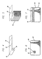
FIG. 6 is a plan view of a plastic card laminated with a full size patch having a precut space for a smart chip; -
FIG. 7 is a plan view of a plastic card laminated with a patch avoiding the area for an encoding stripe; -
FIG. 8 is a schematic of a first patch separation process; -
FIG. 9 is a schematic of a second patch separation process; -
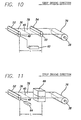
FIG. 10 is a schematic of a third patch separation process; -
FIG. 11 is a schematic of a fourth patch separation process; -
FIG. 12 is a schematic of the cassette loaded with media; -
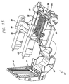
FIG. 13 is a schematic of the cassette with a roller casing removed; -
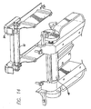
FIG. 14 is a schematic of the underside of the roller casing; -
FIG. 15 is a schematic of the cassette with roller placement; -
FIG. 16 is a schematic of the cassette with the cover opened and media loaded; and -
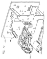
FIG. 17 is a schematic of the cassette and spindle. - The present invention is a new and improved device used to separate perforated media according to claim 1.
- The present invention does not require position markers, as there is no space between the patches. This advantage creates a waste-less process.
- In the first embodiment, perforated, carrier-less media is wound on spools. The media is adapted to be transported through two pairs of adjacent rollers that are used to separate a unit of media from the continuous strip of media by creating a stress on the perforations.
- The embodiment described will refer to 0.0001 inch or 0.00254 mm (i.e.,1 mil.) patches, although other patch thicknesses are available. Further, the invention can easily be adapted to other card and patch thicknesses by persons of ordinary skill in the art.
- The size of the patch (width, length, corner radius and thickness) can be defined according to the dimensions of the card used by a customer and the required level of protection. For example, when using ISO (International Standardization Organization) cards, the patch can be 85 mm by 54 mm.
- Examples of cards using patches are driver's licenses, high security identification badges and tags, student identifications, national identifications, and secure facility access control cards.
-
FIG. 4 is a perspective view of acontinuous strip 76 of pre-cut,carrier-less patches 36 havingperforations 40 and wound to create aconventional spool 38.FIG. 5 is a perspective view of thecontinuous strip 76 of pre-cut,carrier-less patches 36 havingperforations 40 and stacked in accordion fashion. BothFIGS. 4 and 5 show theperforations 40 existing on two ends of eachpatch 36, connecting eachpatch 36 to thenext patch 36 in thestrip 76. - The
patches 36 can both be perforated and linked on either their width or their length. The distance between each perforation between thepatches 36 is defined according to the fragility of theribbon strip 76 material and to achieve the same separation force irrespective of the dimensions of thepatch 36. For example, when the width of the patch is 54 mm, the configuration of the perforation can be 1 mm tie for 4 mm cut. This means that when looking at a perforated edge of a patch, there are a series of 4 mm cut spaces and of 1 mm connected areas that attach one patch to the next patch. The cuts or perforations are parallel to an edge of thepatch 36. -
Figures 6 and 7 show different sized patches.Figure 6 shows apatch 36 having acutout 42 to allow a smart-chip to be placed on acard 44 without being covered by thepatch 36.Figure 7 shows a patch narrower than a full-size card 44 so that thepatch 36 does not cover amagnetic strip 46 on thecard 44. Different types of patches include, but are not limited to: clear full card; clear with magnetic stripe allowance; clear with signature matte; custom holograms; clear with smart chip allowance; and custom OVI (optically variable ink). - In a preferred embodiment the plastic patches are made of polyester or PVC. Temperature-activated glue is then placed on one side to permit the adhesion of the patch to the card. The preferred glue is acrylic and vinylic based, and activated when the card surface reaches around 110 degrees Centigrade. The activation temperature is reached when the patch is placed under a heater roller for lamination.
- In a preferred embodiment the patches are driven and separated by two drive rollers rotating with different speeds to create a stress on the perforated area. By allowing the patches to separate without stopping the driving process, this invention is more efficient.
-
Figure 8 shows a first embodiment having a first set of rollers comprisingupstream drive roller 50 andpressure roller 54 and a second set of rollers comprisingdownstream drive roller 48 andpressure roller 52. Thedrive rollers drive roller 48 is greater than the diameter ofdrive roller 50. For example, if the diameter ofdrive roller 48 is 20mm, then the diameter ofdrive roller 50 is 8mm in order to generate the appropriate tension force of 1 mm tie for 4 mm cut on thestrip 76. - To separate a patch from the strip of patches, the printer or laminator provides a driving torque of 65 N•mm where the linear speed of
drive roller 50 is 200 mm/min and the linear speed ofdrive roller 48 is 500 mm/min. Also, in order to avoid any unexpected separation of the patches, the 4mm cut/1mm tie patch configuration allows a rolling torque of the ribbon supplier of 26 N•mm. - The distance L between driving
roller 48 and drivingroller 50 must be equal to or longer than one patch length, but no longer than two patch lengths to ensure that only oneperforation 40 is always located between the drivingrollers drive rollers perforated areas 40 are betweendrive rollers drive rollers patch 36 which may cause damage to the device. - In the preferred embodiment,
patch 36 separates from the strip when theperforations 40 are betweendrive rollers patch 36 is pulled and driven bydrive roller 48, while thenext patch 78, which is not separated from the strip yet, is pushed and driven bydrive roller 50 to ensure thatpatch 78 is fed betweendrive roller 48 andpressure roller 52. - There are several ways to provide the greater linear speed required by
drive roller 48. The following second, third and fourth embodiments are like the first embodiment with respect to the rollers, the required pressure for patch separation, and the direction the media travels. The second and third embodiments are like the first embodiment with respect to the distance L betweendrive roller 48 and driveroller 50. - The
rollers pressure rollers rollers patches 76. For example, a 60mm pressure roller will exert a force of 1 Kg across the entire length of the pressure roller. -
Figure 9 shows a second embodiment of the separation process where therespective pressure rollers strip 76 as thestrip 76 travels fromupstream drive roller 50 todownstream drive roller 48. -
Motors rollers patches 36 between the sets of rollers. In this embodiment, the diameter ofdrive roller 48 is equal to the diameter ofdrive roller 50. Thepatch 36 travels betweendrive roller 50 andpressure roller 54 and then betweendrive roller 48 andpressure roller 52. The linear speed ofdrive roller 48 is higher than the speed ofdrive roller 50, which creates a tension force on the perforatedarea 40, and causes theadjacent patch 36 to separate at theperforation 40. For example, if the linear speed ofdrive roller 50 is 200mm/min and the linear speed ofdrive roller 48 is 500mm/min, then a tension force of 1mm tie for 4mm cut will cause theperforations 40 between the two sets of rollers to separate. -
Figure 10 shows a third embodiment where a 62 is used to drive thedownstream drive roller 48 so that the linear speed generated bydrive roller 48 is higher than the linear speed generated by drive roller 50 (combined movements), without using two motors. - The
drive roller 48 can be activated by a translator device which can either be linked and driven by a cam or by a trammel and an endless screw. The translator is a device that drives movements. In this case we drive two movements, it moves the roller forward and backwards. For example, if the linear speed ofdrive roller 50 is 200mm/min and the translation speed is 100mm/min, then the linear speed of drive roller 15 is 400mm/min. -
Figure 11 shows a fourth embodiment using a static force to achieve different linear speeds. A tension force may be applied bydownstream rollers first patch 36 while a static pinching device(s) 66 immobilizes the followingpatch 78. The force can be 350g with a speed of 300mm/min. The force and speed may be other values, but the values must take into account the fragility of the perforations on the patch. The distance L betweendrive roller 48 and pinching device(s) 66 must be longer than one patch, but no longer than two patch lengths, to ensure that aperforation 40 is always located between thedrive roller 48 andpressure roller 52 and the pinchingdevice 66. For example, if using an ISO card (85mm by 54mm), then the distance L can be 90mm. -
Figure 12 shows acassette 80 incorporating the embodiment disclosed inFigure 8 , although any of the disclosed separation processes may be incorporated into a cassette. The cassette inFigure 12 shows ahandle 82 to allow a customer access to the interior of thecassette 80. Thecassette 80 can be stored or delivered to a customer separate from a printer or laminator. Customers may use one cassette for each different type of media. In the preferred embodiment, the cassette is made of molded plastic. The molded plastic is less expense than other materials, and allows the customer to receive a consumable cassette. As a consumable cassette, a user can store media within the cassette. The cassette may be made of alternative materials, either metallic or plastic, or a combination of several materials. -
Figure 13 is thecassette 80 ofFigure 12 with thecover 90 open, and shows twobelts 88 coupled to driverollers drive roller 48 has a greater diameter thandrive roller 50. In the preferred embodiment, themotor 60 is coupled to driveroller 48 so that asdrive roller 48 rotates, thebelts 88 will enable driveroller 50 to rotate at the same speed asdrive roller 48. Alternatively, themotor 60 could be coupled to thedrive roller 50 so that asdrive roller 50 rotates, thebelts 88 will enable driveroller 48 to rotate. Thebelts 88 must be long enough to ensure that aperforation 40 is always between thedrive rollers drive roller 48 and driveroller 50 is 90 mm. In the preferred embodiment, having twobelts 88 allow high torque and resistance to fast changes in strength. However, one belt could be used, depending on its material and width. - Between drive
roller 48 and driveroller 50 areridges 86. Theridges 86 help guide the separated patch out of the cassette and also help feed the next patch betweendrive roller 48 and driveroller 50. - When few ridges are used, there are fewer contact points between the
patch 36 and theridges 86, thus the friction between thepatch 36 and theridges 86 is low. The appropriate number ofridges 86 are needed to ensure that the patches remain as flat as possible as the patch travels from the first set of rollers, driveroller 50 andpressure roller 54, to the second set of rollers, driveroller 48 andpressure roller 52. If toofew ridges 86 are used, then a portion of the leading edge of the patch may bump against either driveroller 48 orpressure roller 52 instead of being driven betweendrive roller 48 andpressure roller 52. - In the preferred embodiment, the number of
ridges 86 used allow 20 percent of the area of one side of thepatch 36 to be contacted by theridges 86. - A second set of
ridges 96 is located betweenpressure roller 54 andpressure roller 52 in thecassette cover 90. The second set ofridges 96 perform the same functions as the first set ofridges 86 because the cassette is operable both right side up and upside down. The more flexible the media is, the smaller the distance betweenridges 86 andridges 96 must be when the cassette is closed to ensure the media remains flat and is fed betweendrive roller 48 andpressure roller 52. In the preferred embodiment, this distance is approximately 1 mm. - In the preferred embodiment, the number of
ridges 96 used allow 20 percent of the area of one side of thepatch 36 to be contacted by theridges 96. - When a customer uses the
handle 82 to open thecassette 80, thecassette cover 90 pivots open revealing the interior of thecassette 80. The cassette cover 90 houses pressureroller 54 and the second set ofridges 96. - A roller casing 84 houses pressure
roller 52. Theroller casing 84 is not detachable from thecassette 80 by a user. Many means of attaching the roller casing to the main body of the cassette may be used. In the preferred embodiment, theroller casing 84 is attached to the main body of thecassette 80 by screws (not shown), but clips or other known methods of attachment may be used. Theroller casing 84 has one roundedcover 98 that covers thepressure roller 52. Theroller casing 84 also has twoarms 100 that cover thebelts 88 when theroller casing 84 is attached to thecassette 80. - By enclosing the
belts 88,drive roller 48 andpressure roller 52 with theroller casing 84, dust and debris from thebelts 88 and pulleys (not shown) are prevented from interfering with the patch as it travels from the first set of rollers to the second set of rollers. By enclosing the media with thecover 90, dust and debris from the printer or laminator are prevented from interfering with the media. -
Figure 14 shows thepressure roller 52 coupled to the underside of theroller casing 84. Driveroller 48 is coupled to thecassette 80 andpressure roller 52 is coupled to theroller casing 84 to ensure proper loading of the media. When theroller casing 84 is attached to the main body of thecassette 80,drive roller 48 andpressure roller 52 are offset from each other by approximately 45 degrees.Pressure roller 52 is offset forward of, or further downstream than, driveroller 48. The purpose of having the 45 degree offset is to ensure that thepatch 36 exits from thecassette 80 at a 45 degree angle. Driveroller 48 andpressure roller 52 continue to drive thepatch 36 as it exits thecassette 80. The 45 degree angle is necessary because other mechanisms within the printer using thecassette 80 require an entry angle of 45 degrees. Other printers may not require this offset because the mechanism that thepatch 36 enters after exiting thecassette 80 may not require an entry angle of 45 degrees. - Another reason for the offset is to minimize the sliding between
drive roller 48 andpatch 36 by ensuring that the contact surface betweendrive roller 48 andpatch 36 is large enough when a high driving torque is required to separate thepatch 36 from thestrip 76. In the preferred embodiment, no offset between drivingroller 50 andpressure roller 54 is necessary. -
Figure 15 shows thecassette 80 with theroller casing 84 removed to reveal howdrive roller 48 andpressure roller 52 are offset from each other when theroller casing 84 is attached to thecassette 80. -
Figure 16 shows how a customer loads media into thecassette 80. After the customer has opened thecassette 80 using thehandle 82, the interior of the cassette is exposed. Theroller casing 84 is still attached to thecassette 80. The customer loads a roll of perforated media into amedia support 102. The media is then fed overdrive roller 50. The customer then leaves thefirst patch 36 somewhere betweendrive roller 50 and driveroller 48, but does not feed thefirst patch 36past drive roller 48. - If the customer fed the
first patch 36past drive roller 48, not only would thepatch 36 be exiting thecassette 80 which would cause an interference with the other mechanisms in the printer, but thefirst patch 36 would not separate from the strip ofmedia 76 because separation occurs within thecassette 80 and betweendrive roller 48 and driveroller 50. - After the customer has loaded the media, the
cassette cover 90 must be closed before installing thecassette 80 into the printer. -
Figure 17 shows how thecassette 80 is mounted in the printer. In the preferred embodiment, there are no other special features to thespindle 106 other than ashoulder 108 that axially stops the position of thecassette 80. However, thespindle 106 may be conically shaped for ease of installing or have markings to ensure alignment. - When using the
cassette 80 to laminate cards, the customer must installmedia 76 inside thecassette 80 first, because thecassette 80 is held in the printer or laminator through thecore 110 of thecassette 80 which is also the core of themedia roll 76. The media roll 76 can rotate freely in thecassette 80, but cannot move axially in thecassette 80. When installing thecassette 80 with thestrip 76 inside, thecore 110 is aligned with thespindle 106 of the printer or laminator, and slid onto it until the end of thecore 110 comes in contact with theshoulder 108 of thespindle 106. Then, the customer cannot push thecassette 80 further, and the position of thecassette 80 is properly aligned. - A latching mechanism may be added between the
cassette 80 and the printer, preferably, as far as possible from the spool area. The latching mechanism may be part of the moldedcassette 80 and comprise twolegs 104 having a spring effect. When the customer places thecassette 80 on thespindle 106 and pushes thecassette 80 toward theside wall 112, each of the twolegs 104 will enter a hole (not shown) located on theside wall 112 of the printer. The diameter of the holes is small enough to put a stress on the twolegs 104 as they are being inserted in to the holes and a customer will likely feel some resistance. Before thecassette 80 is completely installed in the printer, the two holes begin to have a larger diameter allowing the twolegs 104 to relax as they continue in the holes. At the entrance the diameter of the hole is 9.2 mm. Then, 3 mm further in is a ring with a diameter of 8.2 mm. This ring is 2mm width. - As soon as the end of the
core 110 comes in contact with theshoulder 108 of thespindle 106, the customer feels thecassette 80 relax as the twolegs 104 enter the two larger holes, then thecassette 80 is properly mounted in the printer. - The latching mechanism holds the
cassette 80 in place with respect to the laminator or printer. The holding force created by thelegs 104 of the latching mechanism is light enough so that removing thecassette 80 manually from the laminator or printer is easy. The easy installation and removal of thecassette 80 have been achieved by rounding the edges of thelegs 104 of the latching mechanism so that they go in and out of the set of holes with a reasonable amount of resistance. Having the latching mechanism as far as possible from thecore 110 allows for a better orientation of thecassette 80 in the laminator or printer, which guarantees that the separated patch will exit thecassette 80 in alignment with other guiding systems of the laminator or printer. - A radial spring loaded system may be implemented between the spindle and the
core 110 to reduce vibrations within thecassette 80. It can be either attached to thespindle 106 or thecore 110. In the preferred embodiment, a leaf spring (not shown) is attached to thespindle 106 to create a radial force on thecore 110. - Other variants include, but are not limited to the following:
- the patches can be linked together by perforations along more than two sides or just one side;
- the patches can be fully separated by the use of a shear stress, such as a guillotine; and
- temperature-activated glue could be applied for the adhesion of both the printed matter and the patch onto the card or on the patch after printing.
- What has been described is a new and improved carrier-less, pre-cut, patch, a method for separating the patches from each other, and a removable cassette for the strip of patches overcoming most, if not all, of the disadvantages inherent in the prior art.
- While certain exemplary embodiments have been described in detail and shown in the accompanying drawings, it is to be understood that such embodiments are merely illustrative of and not restrictive on the broad invention, and that this invention is not to be limited to the specific arrangements and constructions shown and described, since various other modifications may occur to those with ordinary skill in the art.
Claims (26)
- A device used to separate perforated media, the media being in a continuous strip of unsupported patches (24) directly connected to each other by perforations (40), the device comprising:first (50) and second (48) drive rollers, the first drive roller (50) being parallel to and spaced from the second drive roller (48) by a distance L, the distance L being greater than a length of one unit of media, but not more than two units of media;first (54) and second (52) pressure rollers being in communication with the first (50) and second (48) drive rollers, respectively, the first pressure roller (54) being parallel to the second pressure roller (52),wherein the media is adapted to be driven between the first (50) and second (48) drive rollers, respectively, wherein the second drive roller (48) has drive means to drive the second drive roller (48) at a linear speed greater than the linear speed of the first drive roller (50),
characterised in that said device further comprises:a removable cassette body (80) having a media holder (102) and a media exit;wherein
the first drive roller (50) is coupled to the cassette body (80) at a first end adjacent the media holder (102);
the first pressure roller (54) adapted to contact the first drive roller (50); the second drive roller (48) is coupled to the cassette body (80) at a second end adjacent the media exit; and
the second pressure roller (52) is adapted to contact the second drive roller (48). - The device of claim 1 wherein the perforations couple a front end of one patch to the back end of another patch.
- The device according to either of claims 1 or 2, wherein each patch- (24) has rounded edges.
- The device according to any preceding claim 1, wherein the continuous strip (76) of patches is wound around a spool.
- The device according to any of claims 1 to 3, wherein the continuous strip (76) of patches is stacked in accordion fashion.
- The device according to any preceding claim, wherein the configuration of the perforation is 1 mm tie for 4mm cut.
- The device of according to any preceding claim, wherein the patch (24) is narrower than a card the media is to be place on.
- The device according to any preceding claim, wherein the patch (24) has a cutout (42) allowing a portion of a card to remain uncovered after lamination.
- The device according to any preceding claim, wherein the drive means are motors (60).
- The device according to any preceding claim further comprising:a door (90) pivotally coupled to the body (80) adjacent the media holder (102), the door (90) being adapted to pivot between an open loading position and a closed operational position; andthe first pressure roller (54) is coupled to the door (90) and adapted to contact the first drive roller (50) when the door is in the closed operational position, andthe greater linear speed of the second drive roller (48) being adapted to separates- a first patch in surface contact with the second drive roller from a second patch in surface contact with the first drive roller when the door is closed.
- The device according to any preceding claim, wherein the second pressure roller (52) is adapted to contact the second drive roller (48) at an offset from each other to thereby increase the surface contact of the first patch with the second drive roller (48).
- The device according to claim 11, wherein the second pressure roller (52) is adapted to contact the second drive roller (48) 45 degrees, downstream of a media flow, from the first drive roller (50).
- The device of any of claims 10, 11, or 12, wherein the second drive roller (48) has a diameter greater than the first drive roller (50).
- The device of any of claims 10 to 13, further comprising:at least one belt (88) coupled to the first (50) and second (48) drive roller; andat least one motor (60) coupled to the first drive roller and adapted to drive the at least one belt (88) and the second drive roller.
- The device of any of claims 10 to 13, further comprising:at least one belt (88) coupled to the first (50) and second (48) drive roller; andat least one motor (60) coupled to the second drive roller (48) and adapted to drive the at least one belt and the first drive roller.
- The device of claims 14 or 15, further comprising a roller casing (84) having at least one arm to cover (90) the at least one belt (88).
- The device of claim 16, wherein the roller casing (84) is adapted to be removably coupled to the cassette body (80).
- The device of any of claims 10 to 17, further comprising a first set of ridges (86) coupled to the cassette body (80) between the first (50) and second (48) drive rollers and adapted to maintain a media substantially flat and to guide media from the first drive roller (50) to the second driver roller (48).
- The device of claim 18, wherein the first set of ridges (86) are adapted to contact 20% of area of media as it passes over the first set of ridges (86).
- The device of any of claims 10 to 19, further comprising a second set of ridges (96) coupled to the door (90) between an end of the door (90) and the first pressure roller, the second set of ridges cooperating with the first set of ridges (86) to guide media from the first drive (50) roller to the second drive roller (48) when the door is (90) closed.
- The device of claim 20, wherein the second set of ridges (96) are adapted to contact 20% of area of media as a media passes over the second set of ridges (96).
- The device of claims i0 to 21, wherein the device is adapted to be operable in any orientation.
- The device of claims 10 to 22, further comprising a handle (82) coupled to a top of the door (90) and being adapted to open and close the door (90).
- The device of any of claims 10 to 23, wherein the door (90) is adapted to create a core opening through a center of the media holder when the door is in the closed position.
- The device of any of claims 10 to 24, wherein
the first pressure roller (54) is coupled to the door (90) and is adapted to contact the first drive roller (50) only when the door is in the closed position, and
the second pressure roller (52) remains in contact with the second drive roller (48) even when the door is in the open position. - The device of any of claims 10 to 25, wherein the continuous perforated strip (76) of patches is supported by a hollow core (110) inside the cassette body (80) and the device further comprises a -laminator spindle (106) mounted independently of the cassette body (80), the spindle being insertable into the core and having a shoulder (108) for maintaining the core in a predetermined position when the cassette body (80) is mounted in the device with the door in its closed operational position.
Priority Applications (3)
| Application Number | Priority Date | Filing Date | Title |
|---|---|---|---|
| US10/328,287 US20030085248A1 (en) | 2001-04-06 | 2002-12-23 | Carrier-less patch protection including cassette and separation device |
| US10/328,288 US7201343B2 (en) | 2001-04-06 | 2002-12-23 | Carrier-less patch protection including cassette and separation device |
| US10/328,155 US20030089754A1 (en) | 2001-04-06 | 2002-12-23 | Carrier-less patch protection including cassette and separation device |
Applications Claiming Priority (2)
| Application Number | Priority Date | Filing Date | Title |
|---|---|---|---|
| US09/827,646 US20020144770A1 (en) | 2001-04-06 | 2001-04-06 | Carrier-less patch protection including cassette and separation process |
| US827646 | 2001-04-06 |
Publications (3)
| Publication Number | Publication Date |
|---|---|
| EP1247643A2 EP1247643A2 (en) | 2002-10-09 |
| EP1247643A3 EP1247643A3 (en) | 2004-01-21 |
| EP1247643B1 true EP1247643B1 (en) | 2008-04-23 |
Family
ID=25249758
Family Applications (1)
| Application Number | Title | Priority Date | Filing Date |
|---|---|---|---|
| EP20010305552 Expired - Lifetime EP1247643B1 (en) | 2001-04-06 | 2001-06-27 | Device including a cassette for the separation of a carrier-less patch |
Country Status (4)
| Country | Link |
|---|---|
| US (4) | US20020144770A1 (en) |
| EP (1) | EP1247643B1 (en) |
| JP (1) | JP3673492B2 (en) |
| DE (1) | DE60133715D1 (en) |
Families Citing this family (10)
| Publication number | Priority date | Publication date | Assignee | Title |
|---|---|---|---|---|
| US7126716B1 (en) * | 1999-08-20 | 2006-10-24 | Zih Corp. | Printer for printing labels, tags or the like |
| US20020144770A1 (en) | 2001-04-06 | 2002-10-10 | Stephane Mabit | Carrier-less patch protection including cassette and separation process |
| US20070013941A1 (en) * | 2005-07-18 | 2007-01-18 | Zih Corp. | System, printer, and method for distributing data to a plurality of printers |
| GB0515145D0 (en) * | 2005-07-23 | 2005-08-31 | Vivid Lamination Technologies | Improvements in laminating machines |
| US7874509B2 (en) * | 2006-04-12 | 2011-01-25 | Kenney James W | Automated dispenser |
| DE102007058765A1 (en) * | 2007-12-06 | 2009-06-25 | Pago Ag, Grabs | Labeling machine for linerless labels |
| US7603830B2 (en) * | 2008-01-28 | 2009-10-20 | Carol Joyce Witt | Apparatus for automatic belt pressure adjustment for coupon separation |
| US8342374B2 (en) * | 2009-02-11 | 2013-01-01 | Insight Promotions, Llc | Fragile premium separator |
| US10828877B2 (en) | 2016-03-09 | 2020-11-10 | Assa Abloy Ab | Patch lamination device and method |
| CN117140643A (en) * | 2023-09-01 | 2023-12-01 | 中国联合工程有限公司 | A low-temperature insulation composite material drilling and laminating machine and its working method |
Family Cites Families (64)
| Publication number | Priority date | Publication date | Assignee | Title |
|---|---|---|---|---|
| US1790680A (en) | 1931-02-03 | Manifolding machine | ||
| US803574A (en) | 1904-05-03 | 1905-11-07 | Simplex Mfg Company | Stamp-separator. |
| US1268222A (en) * | 1918-01-28 | 1918-06-04 | Joseph F Dwyer | Device for dispensing tickets. |
| US2099314A (en) | 1935-11-07 | 1937-11-16 | Potdevin Machine Co | Cutting-off mechanism for bag making machines and the like |
| US2344720A (en) | 1941-10-18 | 1944-03-21 | United Autographic Register Co | Printing and bursting machine |
| US2513093A (en) | 1945-11-07 | 1950-06-27 | Moore Business Forms Inc | Strip feeding and severing machine |
| US2538425A (en) | 1946-11-27 | 1951-01-16 | Goss Printing Press Co Ltd | Cutting mechanism |
| US2618336A (en) | 1949-11-22 | 1952-11-18 | Standard Register Co | Strip burster |
| FR1106023A (en) | 1955-01-22 | 1955-12-12 | Fomac | Apparatus for separating paper strips along previously established perforation lines |
| US2800180A (en) | 1955-07-06 | 1957-07-23 | Uarco Inc | Method of bursting unequal width portions from continuous stationery |
| US3036751A (en) * | 1958-08-06 | 1962-05-29 | Bartschi Paul | Apparatus for removing as required, tear-off pieces, particularly postage stamps |
| US3481520A (en) * | 1967-01-03 | 1969-12-02 | Gen Time Corp | Digital quantity measuring apparatus |
| US3484031A (en) | 1967-07-20 | 1969-12-16 | Uarco Inc | Stationery burster |
| US3666151A (en) * | 1970-08-18 | 1972-05-30 | Du Pont Canada | Apparatus for and method of severing film |
| US3672551A (en) | 1970-11-04 | 1972-06-27 | Uarco Inc | Burster with interrupted drive |
| US3888399A (en) * | 1972-10-31 | 1975-06-10 | Pitney Bowes Inc | Bursting apparatus |
| US3860192A (en) * | 1973-10-09 | 1975-01-14 | Singer Co | Tape feed mechanism |
| US4022364A (en) | 1974-09-16 | 1977-05-10 | Uarco Incorporated | Burster |
| US3987949A (en) * | 1975-10-20 | 1976-10-26 | International Business Machines Corporation | Forms bursting apparatus |
| US4025023A (en) * | 1975-10-31 | 1977-05-24 | International Business Machines Corporation | Burster apparatus |
| NL7806356A (en) | 1978-06-12 | 1979-12-14 | Handelsmaatschappij Ploeg Mark | Ticket dispensing machine from strip - has driving roller at outlet running faster than roller at inlet |
| US4222511A (en) | 1978-10-06 | 1980-09-16 | Swingline, Inc. | Low noise burster |
| DE2851894A1 (en) * | 1978-11-30 | 1980-06-12 | Agfa Gevaert Ag | DEVICE FOR SEPARATING PRE-PERFORATED TAPES, PREFERABLY CONTINUOUS BAGS |
| US4261497A (en) * | 1979-01-18 | 1981-04-14 | Pitney Bowes Inc. | Bursting apparatus |
| US4375189A (en) * | 1981-04-30 | 1983-03-01 | Hobart Corporation | Label printer |
| US4688708A (en) * | 1984-01-09 | 1987-08-25 | Pitney Bowes Inc. | Bursting machine |
| JPH0330365Y2 (en) * | 1986-02-18 | 1991-06-27 | ||
| US4814216A (en) * | 1986-10-17 | 1989-03-21 | Graphic Controls Corporation | Transparency medium for automatic printers |
| US4982337A (en) * | 1987-12-03 | 1991-01-01 | Burr Robert L | System for distributing lottery tickets |
| IT215262Z2 (en) | 1988-11-21 | 1990-09-11 | Meschi Ind Grafica | STRAPPERINA FOR TAPES OF MATERIALS IN SHEETS SUCH AS PAPER TAPES. |
| US5079901A (en) * | 1989-05-08 | 1992-01-14 | Carol J. Witt | Coupon inserting apparatus and method |
| US5141142A (en) * | 1989-08-28 | 1992-08-25 | Pitney Bowes Inc. | Method and apparatus for bursting perforated web material |
| CA2024481C (en) * | 1990-08-31 | 1995-12-26 | Steven Kunreuther | Apparatus for separating labels from a perforated sheet |
| EP0479385B1 (en) * | 1990-10-03 | 1995-12-27 | Industria Grafica Meschi S.r.l. | Apparatus for the high speed piling up of paper sheets or continuous band with, tearing separation along preperforation lines |
| US5388746A (en) * | 1990-11-09 | 1995-02-14 | Fmc Corporation | Separator/folder bag machine |
| IT1255007B (en) * | 1991-07-01 | 1995-10-11 | Altergon Sa | SOLUBLE SALTS OF IBUPROFEN C0N N- (2-HYDROXYETHYL) PYROLIDINE AND PHARMACEUTICAL COMPOSITIONS CONTAINING THEM. |
| DE59206990D1 (en) * | 1991-08-13 | 1996-10-02 | Agfa Gevaert Ag | Photographic copier with a storage cassette |
| JPH061514A (en) | 1992-06-17 | 1994-01-11 | Canon Inc | Sheet transport device |
| US5375785A (en) * | 1992-12-02 | 1994-12-27 | Georgia-Pacific Corporation | Automatic web transfer mechanism for flexible sheet dispenser |
| US5549233A (en) * | 1993-01-29 | 1996-08-27 | C. Joyce Witt | Coupon inserter |
| US5540369A (en) * | 1993-12-07 | 1996-07-30 | Moore Business Forms, Inc. | Detaching linerless labels |
| US5584962A (en) * | 1994-05-20 | 1996-12-17 | Bradshaw; Franklin C. | Laminating and adhesive transfer apparatus |
| DE4447782C2 (en) | 1994-11-14 | 2000-08-31 | Windmoeller & Hoelscher | Separating device for separating perforated hose sections |
| US6149045A (en) * | 1995-04-26 | 2000-11-21 | Toshiba Tec Kabushiki Kaisha | Paper sheet supplying apparatus having a raised central region for preventing a paper sheet from skewing as the sheet is fed |
| US5853117A (en) * | 1995-10-31 | 1998-12-29 | Moore Business Forms, Inc. | Separator for linerless labels |
| US5836498A (en) * | 1996-04-10 | 1998-11-17 | Interlott Technologies, Inc. | Lottery ticket dispenser |
| US5783024A (en) * | 1996-04-12 | 1998-07-21 | Nbs Imaging Systems, Inc. | Apparatus for applying heat bondable lamina to a substrate |
| US5803261A (en) * | 1996-10-31 | 1998-09-08 | C. Joyce Witt | Three dimensional insert construction |
| US5845462A (en) * | 1996-12-10 | 1998-12-08 | Northfield Corporation | Coupon inserter |
| US5806993A (en) * | 1997-03-18 | 1998-09-15 | Comtec Information Systems, Inc. | Portable interactive miniature printer |
| JP3505960B2 (en) | 1997-06-11 | 2004-03-15 | 株式会社 沖情報システムズ | Ticketing device |
| US5860753A (en) * | 1997-12-18 | 1999-01-19 | Comtec Information Systems, Inc. | Mechanism for centering rolls of paper stock supplied for printing |
| US6019865A (en) * | 1998-01-21 | 2000-02-01 | Moore U.S.A. Inc. | Method of forming labels containing transponders |
| JP3454348B2 (en) * | 1998-06-12 | 2003-10-06 | 富士写真フイルム株式会社 | Conveyor for photosensitive material |
| US6004053A (en) * | 1998-09-11 | 1999-12-21 | Comtec Informationsystems, Inc. | Printer apparatus |
| US6409872B1 (en) * | 1998-11-06 | 2002-06-25 | Fargo Electronics, Inc. | Identification card printer and laminator |
| JP4194205B2 (en) * | 1999-05-14 | 2008-12-10 | キヤノン株式会社 | Inkjet recording device |
| US6431492B1 (en) * | 1999-10-27 | 2002-08-13 | Zih Corp. | Integrated adjustable core support and medium guide device |
| US20020117528A1 (en) | 2000-03-08 | 2002-08-29 | Interlott Technologies, Inc. | Lottery ticket dispenser transport mechanism |
| US20020144770A1 (en) | 2001-04-06 | 2002-10-10 | Stephane Mabit | Carrier-less patch protection including cassette and separation process |
| US6712463B2 (en) * | 2001-09-07 | 2004-03-30 | Canon Kabushiki Kaisha | Recording apparatus |
| US6609844B1 (en) * | 2001-11-09 | 2003-08-26 | Zih Corp. | Portable printer having automatic print alignment |
| JP4073008B2 (en) * | 2002-09-17 | 2008-04-09 | キヤノン株式会社 | Recording device |
| JP4496519B2 (en) * | 2003-09-29 | 2010-07-07 | 富士ゼロックス株式会社 | Sheet conveying apparatus and image forming apparatus |
-
2001
- 2001-04-06 US US09/827,646 patent/US20020144770A1/en not_active Abandoned
- 2001-06-27 EP EP20010305552 patent/EP1247643B1/en not_active Expired - Lifetime
- 2001-06-27 DE DE60133715T patent/DE60133715D1/en not_active Expired - Lifetime
- 2001-11-09 JP JP2001345156A patent/JP3673492B2/en not_active Expired - Fee Related
-
2002
- 2002-12-23 US US10/328,155 patent/US20030089754A1/en not_active Abandoned
- 2002-12-23 US US10/328,287 patent/US20030085248A1/en not_active Abandoned
- 2002-12-23 US US10/328,288 patent/US7201343B2/en not_active Expired - Lifetime
Also Published As
| Publication number | Publication date |
|---|---|
| EP1247643A2 (en) | 2002-10-09 |
| US20030089754A1 (en) | 2003-05-15 |
| JP3673492B2 (en) | 2005-07-20 |
| JP2002312752A (en) | 2002-10-25 |
| DE60133715D1 (en) | 2008-06-05 |
| US20030085248A1 (en) | 2003-05-08 |
| US20030085249A1 (en) | 2003-05-08 |
| US20020144770A1 (en) | 2002-10-10 |
| EP1247643A3 (en) | 2004-01-21 |
| US7201343B2 (en) | 2007-04-10 |
Similar Documents
| Publication | Publication Date | Title |
|---|---|---|
| RU2158202C2 (en) | Device for application and transfer (modifications), feed roller assembly, replaceable cassette | |
| USRE38553E1 (en) | Card laminating apparatus | |
| US6159327A (en) | Apparatus and method for applying heat bondable lamina to a substrate | |
| EP2933102B1 (en) | Indent printing apparatus | |
| JP2002529342A (en) | Identification card printer and stacking device | |
| EP1553036B1 (en) | Tape-like body delivering device, and label tape printing device | |
| US7201343B2 (en) | Carrier-less patch protection including cassette and separation device | |
| EP1955857B1 (en) | Printer with thermal activation device and printing method | |
| RU2368508C2 (en) | Cassette with low friction coefficient | |
| JP4858535B2 (en) | Tape printer | |
| US5690774A (en) | Apparatus and method for maintaining the confidentiality of printed information | |
| US20090266486A1 (en) | Sheet peeling apparatus and method | |
| EP0631541A1 (en) | Apparatus and method for maintaining the confidentiality of printed information | |
| JP3837896B2 (en) | Laminating equipment | |
| JP2010530320A (en) | Method for increasing production amount of transfer film subjected to stamping process and apparatus suitable for the method | |
| WO2025094712A1 (en) | Recording device | |
| JP4529742B2 (en) | Printing device | |
| JPH11348119A (en) | Sheet roll |
Legal Events
| Date | Code | Title | Description |
|---|---|---|---|
| PUAI | Public reference made under article 153(3) epc to a published international application that has entered the european phase |
Free format text: ORIGINAL CODE: 0009012 |
|
| AK | Designated contracting states |
Kind code of ref document: A2 Designated state(s): AT BE CH CY DE DK ES FI FR GB GR IE IT LI LU MC NL PT SE TR |
|
| AX | Request for extension of the european patent |
Free format text: AL;LT;LV;MK;RO;SI |
|
| PUAL | Search report despatched |
Free format text: ORIGINAL CODE: 0009013 |
|
| AK | Designated contracting states |
Kind code of ref document: A3 Designated state(s): AT BE CH CY DE DK ES FI FR GB GR IE IT LI LU MC NL PT SE TR |
|
| AX | Request for extension of the european patent |
Extension state: AL LT LV MK RO SI |
|
| 17P | Request for examination filed |
Effective date: 20040301 |
|
| 17Q | First examination report despatched |
Effective date: 20040817 |
|
| AKX | Designation fees paid |
Designated state(s): DE FR GB IT |
|
| RAP1 | Party data changed (applicant data changed or rights of an application transferred) |
Owner name: ZIH CORPORATION |
|
| RAP1 | Party data changed (applicant data changed or rights of an application transferred) |
Owner name: ZIH CORPORATION |
|
| RIC1 | Information provided on ipc code assigned before grant |
Ipc: B65H 35/10 20060101ALI20070927BHEP Ipc: B26F 3/00 20060101ALI20070927BHEP Ipc: B32B 38/00 20060101AFI20070927BHEP |
|
| RTI1 | Title (correction) |
Free format text: DEVICE INCLUDING A CASSETTE FOR THE SEPARATION OF A CARRIER-LESS PATCH |
|
| GRAP | Despatch of communication of intention to grant a patent |
Free format text: ORIGINAL CODE: EPIDOSNIGR1 |
|
| GRAS | Grant fee paid |
Free format text: ORIGINAL CODE: EPIDOSNIGR3 |
|
| GRAA | (expected) grant |
Free format text: ORIGINAL CODE: 0009210 |
|
| AK | Designated contracting states |
Kind code of ref document: B1 Designated state(s): DE FR GB IT |
|
| REG | Reference to a national code |
Ref country code: GB Ref legal event code: FG4D |
|
| REF | Corresponds to: |
Ref document number: 60133715 Country of ref document: DE Date of ref document: 20080605 Kind code of ref document: P |
|
| PG25 | Lapsed in a contracting state [announced via postgrant information from national office to epo] |
Ref country code: DE Free format text: LAPSE BECAUSE OF FAILURE TO SUBMIT A TRANSLATION OF THE DESCRIPTION OR TO PAY THE FEE WITHIN THE PRESCRIBED TIME-LIMIT Effective date: 20080724 |
|
| EN | Fr: translation not filed | ||
| PLBE | No opposition filed within time limit |
Free format text: ORIGINAL CODE: 0009261 |
|
| STAA | Information on the status of an ep patent application or granted ep patent |
Free format text: STATUS: NO OPPOSITION FILED WITHIN TIME LIMIT |
|
| 26N | No opposition filed |
Effective date: 20090126 |
|
| PG25 | Lapsed in a contracting state [announced via postgrant information from national office to epo] |
Ref country code: IT Free format text: LAPSE BECAUSE OF FAILURE TO SUBMIT A TRANSLATION OF THE DESCRIPTION OR TO PAY THE FEE WITHIN THE PRESCRIBED TIME-LIMIT Effective date: 20080423 |
|
| PG25 | Lapsed in a contracting state [announced via postgrant information from national office to epo] |
Ref country code: FR Free format text: LAPSE BECAUSE OF FAILURE TO SUBMIT A TRANSLATION OF THE DESCRIPTION OR TO PAY THE FEE WITHIN THE PRESCRIBED TIME-LIMIT Effective date: 20090227 |
|
| REG | Reference to a national code |
Ref country code: GB Ref legal event code: 732E Free format text: REGISTERED BETWEEN 20190404 AND 20190410 |
|
| PGFP | Annual fee paid to national office [announced via postgrant information from national office to epo] |
Ref country code: GB Payment date: 20200525 Year of fee payment: 20 |
|
| REG | Reference to a national code |
Ref country code: GB Ref legal event code: PE20 Expiry date: 20210626 |
|
| PG25 | Lapsed in a contracting state [announced via postgrant information from national office to epo] |
Ref country code: GB Free format text: LAPSE BECAUSE OF EXPIRATION OF PROTECTION Effective date: 20210626 |