EP1247603A2 - Casting method and casting apparatus - Google Patents
Casting method and casting apparatus Download PDFInfo
- Publication number
- EP1247603A2 EP1247603A2 EP20020007342 EP02007342A EP1247603A2 EP 1247603 A2 EP1247603 A2 EP 1247603A2 EP 20020007342 EP20020007342 EP 20020007342 EP 02007342 A EP02007342 A EP 02007342A EP 1247603 A2 EP1247603 A2 EP 1247603A2
- Authority
- EP
- European Patent Office
- Prior art keywords
- cavity
- molten metal
- head portion
- feeder head
- molding die
- Prior art date
- Legal status (The legal status is an assumption and is not a legal conclusion. Google has not performed a legal analysis and makes no representation as to the accuracy of the status listed.)
- Withdrawn
Links
Images


Classifications
-
- B—PERFORMING OPERATIONS; TRANSPORTING
- B22—CASTING; POWDER METALLURGY
- B22D—CASTING OF METALS; CASTING OF OTHER SUBSTANCES BY THE SAME PROCESSES OR DEVICES
- B22D27/00—Treating the metal in the mould while it is molten or ductile ; Pressure or vacuum casting
- B22D27/18—Measures for using chemical processes for influencing the surface composition of castings, e.g. for increasing resistance to acid attack
-
- B—PERFORMING OPERATIONS; TRANSPORTING
- B22—CASTING; POWDER METALLURGY
- B22D—CASTING OF METALS; CASTING OF OTHER SUBSTANCES BY THE SAME PROCESSES OR DEVICES
- B22D21/00—Casting non-ferrous metals or metallic compounds so far as their metallurgical properties are of importance for the casting procedure; Selection of compositions therefor
- B22D21/002—Castings of light metals
- B22D21/007—Castings of light metals with low melting point, e.g. Al 659 degrees C, Mg 650 degrees C
-
- B—PERFORMING OPERATIONS; TRANSPORTING
- B22—CASTING; POWDER METALLURGY
- B22D—CASTING OF METALS; CASTING OF OTHER SUBSTANCES BY THE SAME PROCESSES OR DEVICES
- B22D27/00—Treating the metal in the mould while it is molten or ductile ; Pressure or vacuum casting
- B22D27/003—Treating the metal in the mould while it is molten or ductile ; Pressure or vacuum casting by using inert gases
-
- B—PERFORMING OPERATIONS; TRANSPORTING
- B22—CASTING; POWDER METALLURGY
- B22D—CASTING OF METALS; CASTING OF OTHER SUBSTANCES BY THE SAME PROCESSES OR DEVICES
- B22D27/00—Treating the metal in the mould while it is molten or ductile ; Pressure or vacuum casting
- B22D27/006—Treating the metal in the mould while it is molten or ductile ; Pressure or vacuum casting by using reactive gases
Definitions
- the present invention relates to a casting method and a casting apparatus, and more particularly to a casting method and a casting apparatus in which a cast product having a desired shape is cast by allowing molten metal poured into an cavity of a molding die and a reducing compound to be contacted with each other whereby an oxide film formed on a surface of the above-described molten metal is reduced.
- FIG. 8 A molding die to be adopted by this modified aluminum casting method is shown in Fig. 8.
- the molding die 100 thus shown in Fig. 8 is such a molding die made of metal as is used in a gravity casting method; on this occasion, the molding die is of a separate type comprising a lower die 102a and an upper die 102b. By these dies 102a and 102b, formed is a cavity 104 in which a cast product having a desired shape is cast.
- a feeder head portion 108 is formed between a sprue 106 from which molten metal of aluminum or an alloy thereof is poured and the cavity 104, and also air-vent holes 110 from which an air in the cavity 104 is discharged when the molten metal is poured into the cavity 104 is formed.
- a reducing compound that is, a magnesium-nitrogen compound (Mg 3 N 2 ) is introduced into the cavity 104 of the molding die 100, the molten metal of aluminum or the alloy thereof is poured into the sprue 106 of the molding die 100 and, then, the molten metal is filled in the cavity 104 and the feeder head portion 108 while the air is discharged from the air-vent holes 110.
- a magnesium-nitrogen compound Mg 3 N 2
- the molten metal in the cavity 104 is solidified by cooling the molding die 100 in which the molten metal is filled in the cavity 104 and the like as it stands still.
- a void which is caused by shrinkage with solidification of the molten metal is supplemented by allowing a part of the molten metal in the feeder head portion 108 to be flowed down in the cavity 104.
- the improved aluminum casting method is a reduction casting method in which an oxide film formed on a surface of the molten metal of aluminum or the alloy thereof is reduced in the presence of a reducing compound within the cavity 104 of the molding die 100 to decrease a surface tension of the molten metal and, as a result, a flowing property and a running property of the molten metal can be enhanced.
- coating of a coating agent which is to be coated on surfaces of inner walls of the feeder head portion and the cavity aiming for enhancement of a flowing property and the like of the molten metal and the like on which the oxide film is formed can be omitted thereby enabling to promote a reduction of production steps and enhance a transferring property of the molding die 100.
- the cavity 104 of the molding die 100 is forced to have a shape where a narrow portion having a smaller cross-sectional area than that of a terminal portion is formed halfway between the sprue and the terminal portion.
- the cavity 104 is forced to have a shape where a first cavity portion 104a in which a molten metal inlet of the cavity 104 is arranged and a second cavity portion 104b, that is, the terminal portion are connected with a narrow portion 104c which is formed narrower than the first cavity portion 104a and the second cavity portion 104b (hereinafter, also referred to only as cavity portion 104a and cavity portion 104b respectively, or as cavity portions 104a and 104b collectively).
- the reducing compound that is, the magnesium-nitrogen compound (Mg 3 N 2 )
- the molten metal of aluminum or the alloy thereof poured into the sprue 106 is then poured into the first cavity portion 104a and, thereafter, poured into the second cavity portion 104b via the narrow portion 104c.
- Such pouring, i.e., filling of the molten metal in the cavity 104 is performed in a short period of time by allowing an oxide film formed on the surface of the molten metal to be reduced in the presence of the reducing compound.
- the molten metal filled in the narrow portion 104c of the cavity 104 is smaller in quantity than that in the cavity portions 104a and 104b and faster in cooling rate than that filled in the cavity portions 104a and 104b, the molten metal filled in the narrow portion 104c is solidified earlier than that filled in the second cavity portion 104b.
- the second cavity portion 104b is not replenished with the molten metal filled in the first cavity portion 104a and the feeder head portion 108, that is, an effect of feeding the molten metal can not be expected whereupon there is a fear that a shrinkage hole or the like may be generated in an obtained cast product.
- the portion is cut off to be disposed. Even when it is considered that the thus-cut off portion is reused after being melted again, a loss of energy must be expected.
- feeder head portions in a plurality of different places increases a capacity of a part of non-cast product, decreases a yield of the cast product of the molten metal poured into the molding die 100 and, accordingly, increases a loss in workability and energy.
- an object of the present invention is to provide a casting method and a casting apparatus in which, when casting is performed using a molding die in which a number of a feeder head portion to be formed between a sprue and a cavity having a complicated shape is allowed to be as small as possible, a shrinkage hole or the like which is caused by shrinkage with solidification of the molten metal filled in the cavity and which is generated in an obtained cast product can be prevented.
- a cooling rate of molten metal filled in a feeder head portion 108 and a narrow portion 104c of the cavity 104 can be made slower by coating a coating agent having a heat insulating effect only on surfaces of inner walls of the feeder head portion 108 and the narrow portion 104c of the cavity 104, compared with a case in which the surfaces of the inner walls of the feeder head portion 108 and the narrow portion 104c of the cavity 104 are not coated by the coating agent.
- the present inventors have found that the shrinkage hole or the like which is caused by shrinkage with solidification of the molten metal filled in the second cavity portion 104b of the cavity 104 and which is generated in an obtained cast product can be prevented by allowing the feeder head portion 108 and the narrow portion 104c of the molding die 100 to have a higher heat insulating property than other portions of the molding die 100 to attain the present invention.
- a casting method for casting a desired shape of a cast product by allowing molten metal poured into a cavity of a molding die and a reducing compound to be contacted with each other while reducing an oxide film formed on a surface of the molten metal comprising the steps of:
- a casting apparatus for performing a casting while an oxide film formed on a surface of a molten metal is reduced by allowing the molten metal and a reducing compound to be contacted with each other, comprising:
- the present invention can preferably be adopted, when the molding die comprising the feeder head portion, arranged between the sprue from which the molten metal is poured and the cavity, and the cavity in which a narrow portion that has a smaller cross-sectional area than the terminal portion is arranged halfway between an inlet, which is in a side of the feeder head portion, of the cavity connected with the feeder head portion and the terminal portion thereof, wherein the feeder head portion and the narrow portion are formed such that they have a higher heat insulating property than the terminal portion, is used.
- a difference of heat insulation can easily be provided between the feeder head portion and the terminal portion of the cavity by forming a part of the molding die, in which the feeder head portion is arranged, by a material that has a higher heat insulating property than a material that forms the terminal portion of the cavity of the molding die.
- a difference of heat insulation can easily be provided between the narrow portion and the terminal portion even in the cavity by forming a part of the molding die, in which the narrow portion of the cavity is arranged, by a material that has a higher heat insulating property than a material that forms the terminal portion of the cavity.
- a difference of heat insulation can easily be provided between the feeder head portion and the narrow portion of the cavity, and the terminal portion of the cavity by using the molding die in which a heat insulating treatment, such as an application of a heat insulating coating agent or the like that is non-reactive to a reducing compound which contacts the molten metal, is performed on a surface of an inner wall of each of the feeder head portion and the narrow portion of the cavity, and the heat insulating treatment is not performed on a surface of an inner wall of the terminal portion of the cavity.
- a heat insulating treatment such as an application of a heat insulating coating agent or the like that is non-reactive to a reducing compound which contacts the molten metal
- a part of the molding die, in which the feeder head portion is arranged can be used as a common member by using the molding die in which a part of the molding die, in which the feeder head portion is arranged, is constructed such that the part is detachable from a cavity portion of the molding die.
- a magnesium-nitrogen compound which is obtained by allowing a magnesium gas and a nitrogen gas to be reacted with each other as raw materials can preferably be used as the reducing compound.
- blocking or the like by the reducing compound in a halfway of an introducing passage leading to the cavity can be prevented by arranging a molten metal-introducing passage that introduces the molten metal into the feeder head portion and an introducing passage that introduces a raw material of a reducing compound into the cavity such that the reducing compound is generated in the cavity in a part of the molding die in which the feeder head portion is arranged.
- a difference of heat insulation is partially provided in the feeder head portion and the cavity such that the molten metal filled in the feeder head portion, that is formed between the sprue from which the molten metal is poured and the cavity, and the cavity is sequentially solidified in a direction of from a terminal portion of the cavity to the feeder head portion
- FIG. 1 A schematic diagram of a casting apparatus according to the present invention is shown in Fig. 1.
- a molding die 12 that comprises a cavity 18 connected with a sprue 14 from which molten metal of aluminum or an alloy thereof is poured.
- the molding die 12 is connected with a steel cylinder 20 containing a nitrogen gas by a piping system 22 and, by opening a valve 24 of the piping system 22, the nitrogen gas is poured from a nitrogen gas-introducing port 27 into the cavity 18 to allow an inside of the cavity 18 to be in a nitrogen-gas atmosphere, that is, substantially in a non-oxygen atmosphere.
- a steel cylinder 25 containing an argon gas is connected with a furnace 28 as a generator which generates a metallic gas by a piping system 26 and, by opening a valve 30 which is arranged in the piping system 26, the argon gas is poured into the furnace 28 an inside of which is formed such that it can be heated by a heater 32; on this occasion, in order to generate a magnesium gas as a metallic gas to be described below, a temperature inside the furnace 28 is set to be 800°C or more at which magnesium powders are sublimed.
- a quantity of the argon gas to be poured into the furnace 28 can be adjusted by the valve 30 such that a flowing quantity of the argon gas is allowed to be in a predetermined flowing quantity also between the valve 30 of this piping system 26 and the furnace 28.
- Such a steel cylinder 25 containing the argon gas as described above is connected with a tank 36 containing magnesium powders by a piping system 34 in which a valve 33 is interposed.
- the tank 36 is connected with a piping system 26 positioned in a downstream side of the valve 30 by a piping system 38.
- a valve 40 is also interposed in the piping system 38.
- the furnace 28 is connected with a metallic gas-introducing port 17 of the molding die 12 via a piping system 42; on this occasion, the metallic gas which has been gasified in the furnace 28 is introduced into the cavity 18 via the metallic gas-introducing port 17.
- a valve 45 is also interposed in the piping system 42.
- the quantity of the argon gas to be poured into the cavity 18 can be adjusted by the valve 45.
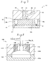
- the molding die 12 used in the casting apparatus shown in Fig. 1 comprises a lower die 21, an upper die 23 and an adaptor 31 as shown in Fig. 2A.
- the upper die 23 comprises a metallic plate 29 and an inserting plate 35 comprising a material, which has a higher heat insulating property than a metal, such as ceramic.
- the adaptor 31 is formed by firing calcium carbonate.
- This molding die 12 is of a separate type in which these members are laminated with one another in a separable manner.
- the cavity 18 in which the cast product having a desired shape is cast is formed by the lower die 21 and the metallic plate 29 of the upper die 23.
- a first cavity portion 18a in which a molten metal inlet of the cavity 18 is arranged and a terminal portion, that is, a second cavity portion 18b are connected with each other by a narrow portion 18c which is formed narrower than the first cavity portion 18a and the second cavity portion 18b (hereinafter also referred to only as cavity portion 18a and cavity portion 18b respectively, or as cavity portions 18a and 18b collectively).
- a molten metal passage 37 which introduces the molten metal poured into a sprue 14 into the cavity 18 and a feeder head portion 16 are arranged between the sprue 14 which is arranged in an adaptor 31 and into which the molten metal of aluminum or the alloy thereof is poured and the cavity 18.
- the feeder head portion 16 is arranged nearest to the molten metal inlet of the first cavity portion 18a and is mainly formed in an inserting plate 35 which constitutes the upper die 23.
- a cross-sectional area of the feeder head portion 16 is larger than that of the molten metal passage 37; further, a capacity of the feeder head portion 16 is preferably set as being from 5% to 20% of a capacity of the cavity 18.
- exhaust holes 39 which discharge a gas in the cavity 18 are formed in the adaptor 31 and the upper die 21.
- introducing passages 41 which introduces a nitrogen gas led from the nitrogen gas-introducing port 27 into the cavity 18 are formed in the lower die 21.
- each of such exhaust holes 39 and introducing passages 41 which is a hole having an annular cross-sectional shape and into which an inserting body 43 having a square pillar cross-sectional shape is inserted, communicates with an inside of the cavity 18 via a vault shape passages 44.
- the sprue 14, the molten metal passage 37, the metallic gas-introducing port 17, the metallic gas-introducing passage 46 and a part of the exhaust hole 39 are arranged in the adaptor 31 which is formed by firing calcium sulfate. It is required to form the molten metal passage 37 and other members in accordance with a shape of the cavity 18 and an arrangement of a pushing pin (not shown) which pushes the cast product out and the like, but such a requirement can be satisfied by arranging the molten metal passage 37 and the like adapted for the cast product to be cast in the adaptor 31.
- the feeder head portion 16 is substantially formed in an inserting plate 35 made of a material such as ceramic which has a substantially higher heat insulating property than a metal.
- the feeder head portion 16 is formed such that it has a higher heat insulating property than the cavity portions 18a and 18b of the cavity 18 in which metallic surfaces are exposed, defined by the metallic lower die 21 and a metallic plate 29 which constitutes the upper die 23.
- a heat insulating treatment such as coating of a heat insulating coating agent and the like is performed on an surface of the inner wall of each of the narrow portions 18c of the cavity 18 whereupon the narrow portions 18c is formed such that they have a higher heat insulating property than the cavity portions 18a and 18b in which metallic surfaces thereof are exposed.
- heat insulating coating agent a high heat insulating coating agent, which is non-reactive to a reducing compound to be described below, is used.
- coating agents include, for example, a non-oxide type coating agent such as ceramic-compounded graphite and the like.
- a treatment which subjects each of the metallic surfaces exposed on the surface of the inner walls thereof to a heating treatment to convert it into iron tetroxide surfaces or another treatment such as nitridation processing can advantageously be adopted.
- the feeder head portion 16 of the molding die 12 and the narrow portions 18c such that each of them has a higher heat insulating property than the cavity portions 18a and 18b, and the cooling rate of the molten metal filled in the feeder head portion 16 and the narrow portions 18c can be made slower than that of the molten metal filled in the cavity portions 18a and 18b whereupon a large difference of cooling rate can be established between the feeder head portion 16 and the cavity portions 18a and 18b.
- the molten metal filled in the feeder head portion 16 can sufficiently exert an effect of feeding the molten metal which flows into the cavity portions 18a and 18b compared with the molding die 100 (Fig. 9) in the related art; such a case as described above will be explained below with reference to Figs. 3A and 3B.
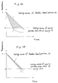
- a point marked as A represents a temperature of the molten metal which is poured into the molding die 12 and a point marked as B represents a temperature of the molten metal which is fully solidified therein. Therefore, an area in which the molten metal filled in the feeder head portion 16 can flows into the cavity portions 18a and 18b to exert a substantial effect of feeding the molten metal is a shaded portion shown in Fig. 3A.
- a molding die 100 of the related art shown in Fig. 9 is coated with a heat insulating coating agent on the surface of the inner wall of the feeder head portion 108 and the surface of the inner wall of each of the cavity portions 104a and 104b, and the molding die 12 is allowed to be a coated die in which thickness of a coating film on the surface of the inner wall of the feeder head portion 108 is larger than that of the coating film on the surface of the inner wall of each of the cavity portions 104a and 104b, the cooling rate of the molten metal filled in the feeder head portion 108 can be made slower than that of the molten metal filled in the cavity portions 104a and 104b, as shown in Fig. 3B.
- the difference of the cooling rate is small compared with the molding die 12 shown in Fig. 3A whereupon the area in which the molten metal filled in the feeder head portion 108 can flow into the cavity portions 104a and 104b to exert a substantial effect of feeding the molten metal is also narrow.
- the difference of the cooling rate is large compared with the molding die 100 of the related art shown in Fig. 3B whereupon, since the area in which the substantial effect of feeding the molten metal can be exerted is wide, even when the feeder head portion is allowed to be smaller in size, the difference of solidification time of molten metal between the molten metal filled in the feeder head portion 16 and that filled in the cavity portions 18a and 18b constituting the cavity 18 can be secured.
- the narrow portion 18c which connects the cavity portion 18a with the cavity portion 18b is formed such that it has a higher heat insulating property than the cavity portions 18a and 18b.
- the molten metal filled in the narrow portion 18c as a part of the molten metal filled in the cavity 18 is solidified earlier than the molten metal filled in the second cavity 18b and that a shrinkage hole and the like caused by shrinkage with solidification of the molten metal filled in the second cavity portion 18b is generated.
- An order of solidification of the molten metal filled in the cavity 18 and the feeder head portion 16 of the molding die 12 shown in Figs. 1 to 2B is changeable in accordance with not only an intense of the heat insulating property in each portion, but also a quantity, a heat releasing area and the like of the molten metal filled in each of the cavity portions 18a and 18b, the narrow portions 18c and the feeder head portion 16.
- the order of solidification of the filled molten metal can be adjusted by adjusting an intense of the heat insulating treatment to be performed on the surface of the inner wall of the narrow portion 18c such that it is set as being from the second cavity portion 18b to the narrow portion 18c to the first cavity portion 18a to the feeder head portion 16 in this order.
- Fig. 3A it can be attained not only by setting the cooling rate of the molten metal filled in the cavity 18 as being 500°C /min or more (preferably 700°C /min or more) but also by setting the cooling rate of the molten metal poured into the feeder head portion 16 as being less than 500°C /min (preferably 300°C /min or less) in order to fully secure the difference of solidification time of the molten metal between the molten metal filled in the feeder head portion 16 and the molten metal filled in the cavity portions 18a and 18b of the cavity 18. Particularly, it is preferable to adjust the difference of the cooling rate therebetween to be 200°C/min or more.
- a space between dendrites of aluminum filled and then solidified in the cavity 18 in which the cooling rate is adjusted to be 500°C/min or more is less than 25 ⁇ m at an average whereas that between dendrites of aluminum filled and then solidified in the feeder head portion 16 in which the cooling rate is adjusted to be less than 500°C/min is less than 25 ⁇ m at an average.
- the space between such dendrites of aluminum is small indicates that a crystal structure of aluminum is dense; this feature is advantageous, since a mechanical strength and the like of an obtained aluminum cast product can be enhanced. For this reason, it is preferable that the space between the dendrites of aluminum is allowed to be 23 ⁇ m or less and particularly 20 ⁇ m or less.
- a space between the dendrites is larger than that in a part of aluminum filled and solidified in the cavity 18 and, accordingly, a mechanical strength in the former part is inferior to that in the latter part; however, since the former part can be cut off from a product which is the latter part, there causes no problem.
- valve 24 When aluminum casting is performed by using a casting apparatus 10 shown in Figs. 1 to 2B, firstly, the valve 24 is opened and a nitrogen gas is introduced from the steel cylinder 20 containing the nitrogen gas into the cavity 18 of the molding die 12 via the piping system 22 thereby discharging an air present in the cavity 18 by the nitrogen gas.
- the air present in the cavity 18 is discharged through exhaust holes 39 whereupon an inside of the cavity 18 is allowed to be in a nitrogen gas atmosphere, that is, substantially in a non-oxygen atmosphere.
- the valve 24 is closed.
- the valve 30 is opened and the argon gas is poured from the steel cylinder 20 containing the argon gas to into the furnace 28 to allow an inside of the furnace 28 to be in a non-oxygen condition.
- valve 30 is closed and, then, the valve 40 is opened to send magnesium powders contained in the tank 38 into the furnace 28 along with the argon gas by an argon gas pressure.
- the furnace 28 is beforehand heated by the heater 32 to a temperature of 800°C or more at which the magnesium powders are sublimed. By taking this arrangement, the magnesium powders sent into the furnace 28 are sublimed to be a magnesium gas.
- valve 40 is closed and, then, the valve 30 and the valve 45 are opened to pour the magnesium gas into the cavity 18 via the piping system 42, the metallic gas-introducing port 17 of the molding die 12, the metallic gas-introducing passage 46, the molten metal passage 37 and the feeder head portion 16 while pressure and a flow rate of the argon gas are adjusted.
- the valve 45 is closed and the valve 24 is opened to pour the nitrogen gas from the nitrogen gas introducing port 17 into the cavity 18 via the introducing passages 41.
- the magnesium gas and the nitrogen gas are allowed to be reacted with each other in the cavity 18 to generate the magnesium-nitrogen compound (Mg 3 N 2 ).
- This magnesium-nitrogen compound is deposited on the surface of the inner wall of the cavity 18 in powder form.
- the nitrogen gas is poured into the cavity 18 while the pressure and the flow rate thereof are appropriately adjusted. It is preferable that the nitrogen gas may be preheated before being poured into the cavity 12 in order that a temperature of the molding die 12 is not decreased such that the nitrogen gas and the magnesium gas can easily be reacted with each other.
- the reaction time may be from about 5 seconds to about 90 seconds (preferably from about 15 seconds to about 60 seconds) . Even when the reaction time is longer than 90 seconds, there is a tendency that the temperature of the molding die 12 is decreased to deteriorate a reaction property.
- the molten metal of aluminum is poured from the sprue 12a into the cavity 18 via the molten metal passage 37 and the feeder head portion 16.
- the molten metal poured into the feeder head portion 16 is poured into the second cavity portion 18b via the first cavity portion 18a and the narrow portion 18c.
- Such a pouring operation of the molten metal is continued until the cavity 18, the feeder head portion 16 and the sprue 14 are all filled with the molten metal.
- the molten which has been poured into the cavity 18 is contacted with the magnesium-nitrogen compound deposited on the surface of the inner wall of the cavity 18, and an oxide film on the surface of the molten metal is deprived of oxygen by the magnesium-nitrogen compound whereupon the surface of the molten metal is reduced to pure aluminum.
- the oxygen remaining in the cavity 18 is reacted with the magnesium-nitrogen compound to generate magnesium hydroxide or magnesium oxide which is then taken in the molten metal. Since the thus-generated magnesium oxide or the like is small in quantity and a safe compound, it will not give an adverse effect on a quality of the aluminum cast product to be obtained.
- the magnesium-nitrogen compound forms pure aluminum by depriving the oxide film on the surface of the molten metal of oxygen whereby casting is performed without forming the oxide film on the surface of the molten metal. For this reason, a case in which a surface tension of the molten metal is increased by the oxide film during casting processing is prevented whereupon a wetting property, a flowing property and a running property of the molten metal are allowed to be favorable. As a result, an advantageous cast product excellent in a transferring property (flatness) of a surface texture relative to the surface of the inner wall of the cavity 18 and having no surface fold and the like can be obtained.
- An order of solidification of the molten metal filled in the cavity 18, the feeder head portion 16 and the like is changeable in accordance with not only an intense of the heat insulating property in each portion, but also a quantity, a heat releasing area of the molten metal filled in each of the cavity portions 18a and 18b of the cavity 18, the narrow portion 18c and the feeder head portion 16 and the like.
- the order of solidification of the filled molten metal can be adjusted by adjusting an intense of the heat insulating treatment performed on the surface of the inner wall of the narrow portion 18c. such that it is set as being from the second cavity portion 18b to the narrow portion 18c to the first cavity portion 18a to the feeder head portion 16 in this order.
- a part of the molten metal filled in the feeder head portion 16 and the cavity 18, that is, the molten metal filled in the second cavity portion 18b starts to be solidified and, even when a void is formed in the second cavity portion 18b by shrinkage with solidification of the molten metal, since the molten metal filled in the narrow portion 18c, the first cavity portion 18a and the feeder head portion 16 can exhibit a flowing property, the molten metal filled in the first cavity portion 18a and the feeder head portion 16 flows into the second cavity portion 18b via the narrow portion 18c to fill the void generated therein.
- the molten metal filled in the first cavity portion 18a starts to be solidified and, even when a void is formed in the first cavity portion 18a by shrinkage with solidification of the molten metal, since the molten metal filled in the feeder head portion 16 can exhibit a flowing property, the molten metal filled in the feeder head portion 16 flows into the first cavity portion 18a to fill the void generated therein.
- the void generated by shrinkage with solidification of the molten metal filled in the cavity portions 18a and 18b can be supplemented with the molten metal and, as a result, a favorable cast product having no shrinkage hole and the like can be cast.
- the feeder head portion 16 is arranged in the inserting plate 35 which has a higher heat insulating property than a metallic plate; however, as shown in Fig. 4A, the feeder head portion 16 may be arranged in the metallic plate 29 which constitutes the upper die 23.
- the surface of the inner wall of the feeder head portion 16 and the surface of the inner wall of the narrow portion 18c is subjected to a heat insulating treatment such as application of a heat insulating coating agent or the like to allow these surfaces to have a higher heat insulating property than the cavity portions 18a and 18b which each has an exposed metallic surface.
- the coating agent which has a high insulating property and is non-reactive to the reducing compound is used.
- coating agents include, for example, a non-oxide type coating agent such as ceramic-compounded graphite and the like.
- the heat insulating coating agent is applied on the surface of the inner wall of each of the feeder head portion 16 and the narrow portion 18c, a starting time of solidification of the molten metal filled in the cavity 18 and the feeder head portion 16 can easily be adjusted by adjusting a coating thickness and the like to set an order thereof as being from the second cavity portion 18b to the narrow portion 18c to the first cavity portion 18a to the feeder head portion 16 in this order.
- the molten metal filled in the feeder head portion 16 is allowed to be flowed into the cavity 18 by a force of gravity; however, it is possible that the adaptor 31 shown in Fig. 4A is arranged to be detachable from the upper die 23 and, when the molten metal filled in the cavity 18 is solidified, the adaptor 31 is detached therefrom and then, by forcibly pushing the molten metal filled in the feeder head portion 16 into a side of the cavity 18, generation of the shrinkage hole or the like in the cast product to be obtained can be reduced.
- Timing of this pushing of the molten metal filled in the feeder head portion 16 is when the molten metal filled in the cavity 18 is substantially in a solidified state and, simultaneously, the molten metal in the feeder head portion 16 maintains a flowing property. It is preferable that the optimum timing of such pushing is preliminarily determined in accordance with each molding die 12 based on experiments, since the optimum timing differs depending on the molding dies 12.
- a piston 47 which can move up and down as shown in Fig. 4B can be used.
- the adaptor 31 may be arranged such that it is detachable or both the inserting plate 35 and the adaptor 31 may be arranged such that thy are detachable.
- the feeder head portion 16 is arranged in the upper die 23; however, since a portion formed by solidifying the molten metal filled in the feeder head portion 16 is a cut-off portion which is to be cut off from the cast product, it is not necessary to arrange it in the upper die 23 made of metal. For this reason, the feeder head portion 16 may be formed through both of the adaptor 31 formed by firing calcium sulfate and the upper die 23. In this case, since the adaptor 31 which has been formed by firing calcium sulfate has a lower heat conductivity, that is, a favorable heat insulating property than the lower and upper dies 21 and 23 made of metal. Therefore, as shown in Fig.
- the feeder head portion 16 is formed such that a capacity of a part of the feeder head portion 16 arranged in the adaptor 31 becomes larger than that of the feeder head portion 16 arranged in the upper die 23, whereby it is possible to improve the heat insulating property of the feeder head portion 16 without applying the heat insulating coating agent on the surface of the inner wall thereof compared with the cavity 18 arranged in the lower and upper dies 21 and 23 made of metal.
- the narrow portions 18c may be arranged in a heat insulating plate 50 comprising a material having a higher heat insulating property than metal, such as ceramic or the like.
- the narrow portions 18c arranged in the heat insulating plate 50 can improve the heat insulating property without applying the heat insulating coating agent on the surface of the inner wall thereof compared with the cavity 18 arranged in the lower and upper dies 21 and 23.
- the furnace 28 shown in Fig. 1, as shown in Fig. 6, may be arranged right above the metallic gas-introducing port 17 of the molding die 12 or a reaction tank 51 in which a magnesium gas as a metallic gas which has been gasified in the furnace 28 and a nitrogen gas as a reactive gas which reacts with the metallic gas are reacted with each other to generate the reducing compound, that is, the magnesium-nitrogen compound (Mg 3 N 2 ) may be arranged right above the metallic gas-introducing port 17 of the molding die 12.
- the magnesium-nitrogen compound Mg 3 N 2
- the first cavity portion 18a which is arranged nearest to the feeder head portion 16 and the second cavity portion 18b as a terminal portion of the cavity 18 are connected with each other by the narrow portion 18c which has been formed narrower than the cavity portions 18a and 18b.
- the molding die 12 in which the feeder head portion 16 and the cavity portions 18b which are terminal portions are connected with each other by narrow portions 18c arranged nearest to the feeder head portion 16 can favorably be adopted.
- the heat insulating coating agent is adapted on the surface of the inner wall of each of the feeder head portion 16 and the narrow portions 18c, the difference of the heat insulation temperature thereon from that on a plurality of cavity portions 18b can easily be provided.
- the feeder head portion 16 may separately be arranged apart from the molten metal passage 37.
- the casting method which uses the molten metal of aluminum or the alloy thereof as molten metal has been described, but the present invention is not limited thereto and can also be applied to a molding method which uses the molten metal of any other metal such as magnesium, iron or the like or an alloy thereof.
Abstract
Description
- The present invention relates to a casting method and a casting apparatus, and more particularly to a casting method and a casting apparatus in which a cast product having a desired shape is cast by allowing molten metal poured into an cavity of a molding die and a reducing compound to be contacted with each other whereby an oxide film formed on a surface of the above-described molten metal is reduced.
- There exist various types of aluminum casting methods such as, for example, a modified aluminum casting method proposed in Japanese Patent Application No. 108078/2000 by two inventors of the present application.
- A molding die to be adopted by this modified aluminum casting method is shown in Fig. 8. The molding die 100 thus shown in Fig. 8 is such a molding die made of metal as is used in a gravity casting method; on this occasion, the molding die is of a separate type comprising a
lower die 102a and anupper die 102b. By thesedies cavity 104 in which a cast product having a desired shape is cast. - Further, in the
upper die 102b, afeeder head portion 108 is formed between asprue 106 from which molten metal of aluminum or an alloy thereof is poured and thecavity 104, and also air-vent holes 110 from which an air in thecavity 104 is discharged when the molten metal is poured into thecavity 104 is formed. - In the improved aluminum casting method using
such molding die 100, after a reducing compound, that is, a magnesium-nitrogen compound (Mg3N2) is introduced into thecavity 104 of themolding die 100, the molten metal of aluminum or the alloy thereof is poured into thesprue 106 of themolding die 100 and, then, the molten metal is filled in thecavity 104 and thefeeder head portion 108 while the air is discharged from the air-vent holes 110. - Next, the molten metal in the
cavity 104 is solidified by cooling themolding die 100 in which the molten metal is filled in thecavity 104 and the like as it stands still. A void which is caused by shrinkage with solidification of the molten metal is supplemented by allowing a part of the molten metal in thefeeder head portion 108 to be flowed down in thecavity 104. - The improved aluminum casting method is a reduction casting method in which an oxide film formed on a surface of the molten metal of aluminum or the alloy thereof is reduced in the presence of a reducing compound within the
cavity 104 of themolding die 100 to decrease a surface tension of the molten metal and, as a result, a flowing property and a running property of the molten metal can be enhanced. - For this feature, in the improved aluminum casting method, coating of a coating agent which is to be coated on surfaces of inner walls of the feeder head portion and the cavity aiming for enhancement of a flowing property and the like of the molten metal and the like on which the oxide film is formed can be omitted thereby enabling to promote a reduction of production steps and enhance a transferring property of the
molding die 100. - Now, depending on the shapes of the cast products, there is a case in which the
cavity 104 of themolding die 100 is forced to have a shape where a narrow portion having a smaller cross-sectional area than that of a terminal portion is formed halfway between the sprue and the terminal portion. For example, there is a case in which thecavity 104 is forced to have a shape where afirst cavity portion 104a in which a molten metal inlet of thecavity 104 is arranged and asecond cavity portion 104b, that is, the terminal portion are connected with anarrow portion 104c which is formed narrower than thefirst cavity portion 104a and thesecond cavity portion 104b (hereinafter, also referred to only ascavity portion 104a andcavity portion 104b respectively, or ascavity portions - In the
cavity 104 shown in Fig. 9, after the reducing compound, that is, the magnesium-nitrogen compound (Mg3N2), is introduced into thecavity 104 of themolding die 100, the molten metal of aluminum or the alloy thereof poured into thesprue 106 is then poured into thefirst cavity portion 104a and, thereafter, poured into thesecond cavity portion 104b via thenarrow portion 104c. Such pouring, i.e., filling of the molten metal in thecavity 104 is performed in a short period of time by allowing an oxide film formed on the surface of the molten metal to be reduced in the presence of the reducing compound. - However, since the molten metal filled in the
narrow portion 104c of thecavity 104 is smaller in quantity than that in thecavity portions cavity portions narrow portion 104c is solidified earlier than that filled in thesecond cavity portion 104b. - For this reason, even when the void is formed while shrinkage is generated with the solidification of the molten metal filled in the
second cavity portion 104b, thesecond cavity portion 104b is not replenished with the molten metal filled in thefirst cavity portion 104a and thefeeder head portion 108, that is, an effect of feeding the molten metal can not be expected whereupon there is a fear that a shrinkage hole or the like may be generated in an obtained cast product. - Meanwhile, though it is possible to solve the shrinkage hole or the like to be generated with the solidification of the molten metal filled in the
second cavity portion 104b by independently arranging the feeder head portion in each of thecavity portions - Further, since a part of the molten metal which is solidified in the
feeder head portion 108 is not a cast product, the portion is cut off to be disposed. Even when it is considered that the thus-cut off portion is reused after being melted again, a loss of energy must be expected. - Therefore, forming feeder head portions in a plurality of different places increases a capacity of a part of non-cast product, decreases a yield of the cast product of the molten metal poured into the
molding die 100 and, accordingly, increases a loss in workability and energy. - Under these circumstances, an object of the present invention is to provide a casting method and a casting apparatus in which, when casting is performed using a molding die in which a number of a feeder head portion to be formed between a sprue and a cavity having a complicated shape is allowed to be as small as possible, a shrinkage hole or the like which is caused by shrinkage with solidification of the molten metal filled in the cavity and which is generated in an obtained cast product can be prevented.
- As a result of an extensive study made by the prevent inventors to solve the above-described problems, it has been found that, in a reduction casting method which allows a reducing compound to be preliminarily present in a
cavity 104 of a molding die 100 (shown in Fig. 8), a cooling rate of molten metal filled in afeeder head portion 108 and anarrow portion 104c of thecavity 104 can be made slower by coating a coating agent having a heat insulating effect only on surfaces of inner walls of thefeeder head portion 108 and thenarrow portion 104c of thecavity 104, compared with a case in which the surfaces of the inner walls of thefeeder head portion 108 and thenarrow portion 104c of thecavity 104 are not coated by the coating agent. - As described above, the present inventors have found that the shrinkage hole or the like which is caused by shrinkage with solidification of the molten metal filled in the
second cavity portion 104b of thecavity 104 and which is generated in an obtained cast product can be prevented by allowing thefeeder head portion 108 and thenarrow portion 104c of themolding die 100 to have a higher heat insulating property than other portions of themolding die 100 to attain the present invention. - Namely, according to the present invention, there is provided a casting method for casting a desired shape of a cast product by allowing molten metal poured into a cavity of a molding die and a reducing compound to be contacted with each other while reducing an oxide film formed on a surface of the molten metal, comprising the steps of:
- using the molding die in which a feeder head portion is arranged between a sprue from which the molten metal is poured and the cavity and a difference of heat insulation is partially provided between the feeder head portion and the cavity such that the molten metal filled in the cavity and the feeder head portion is sequentially solidified in a direction of from a terminal portion of the cavity to the feeder head portion; and
- replenishing the cavity with at least a part of the molten metal filled in the feeder head portion, when a void is formed by shrinkage with solidification of the molten metal filled in the cavity.
-
- Further, according to the present invention, there is provided a casting apparatus for performing a casting while an oxide film formed on a surface of a molten metal is reduced by allowing the molten metal and a reducing compound to be contacted with each other, comprising:
- a molding die having a cavity for receiving the molten metal, a sprue from which the molten metal is poured and a feeder head portion arranged between the sprue and the cavity, wherein a difference of heat insulation is partially provided between the feeder head portion and the cavity such that the molten metal filled in the cavity and the feeder head portion is sequentially solidified in a direction of from a terminal portion of the cavity to the feeder head portion.
-
- The present invention can preferably be adopted, when the molding die comprising the feeder head portion, arranged between the sprue from which the molten metal is poured and the cavity, and the cavity in which a narrow portion that has a smaller cross-sectional area than the terminal portion is arranged halfway between an inlet, which is in a side of the feeder head portion, of the cavity connected with the feeder head portion and the terminal portion thereof, wherein the feeder head portion and the narrow portion are formed such that they have a higher heat insulating property than the terminal portion, is used.
- On this occasion, a difference of heat insulation can easily be provided between the feeder head portion and the terminal portion of the cavity by forming a part of the molding die, in which the feeder head portion is arranged, by a material that has a higher heat insulating property than a material that forms the terminal portion of the cavity of the molding die.
- Further, a difference of heat insulation can easily be provided between the narrow portion and the terminal portion even in the cavity by forming a part of the molding die, in which the narrow portion of the cavity is arranged, by a material that has a higher heat insulating property than a material that forms the terminal portion of the cavity.
- On the other hand, a difference of heat insulation can easily be provided between the feeder head portion and the narrow portion of the cavity, and the terminal portion of the cavity by using the molding die in which a heat insulating treatment, such as an application of a heat insulating coating agent or the like that is non-reactive to a reducing compound which contacts the molten metal, is performed on a surface of an inner wall of each of the feeder head portion and the narrow portion of the cavity, and the heat insulating treatment is not performed on a surface of an inner wall of the terminal portion of the cavity.
- Further, a part of the molding die, in which the feeder head portion is arranged, can be used as a common member by using the molding die in which a part of the molding die, in which the feeder head portion is arranged, is constructed such that the part is detachable from a cavity portion of the molding die.
- According to the present invention, when molten metal of aluminum or an alloy thereof is used as the molten metal, a magnesium-nitrogen compound which is obtained by allowing a magnesium gas and a nitrogen gas to be reacted with each other as raw materials can preferably be used as the reducing compound.
- Further, blocking or the like by the reducing compound in a halfway of an introducing passage leading to the cavity can be prevented by arranging a molten metal-introducing passage that introduces the molten metal into the feeder head portion and an introducing passage that introduces a raw material of a reducing compound into the cavity such that the reducing compound is generated in the cavity in a part of the molding die in which the feeder head portion is arranged.
- In the present invention, a difference of heat insulation is partially provided in the feeder head portion and the cavity such that the molten metal filled in the feeder head portion, that is formed between the sprue from which the molten metal is poured and the cavity, and the cavity is sequentially solidified in a direction of from a terminal portion of the cavity to the feeder head portion
- For this provision, when the molten metal is sequentially solidified in a direction of from the terminal portion of the cavity to the feeder head portion and a void is formed in the cavity caused by shrinkage with solidification of the molten metal, a part of the molten metal filled in the feeder head portion is flowed into the cavity for replenishment, that is, the effect of feeding the molten metal is secured until the molten metal filled in the cavity is fully solidified and, as a result, the shrinkage hole or the like to be generated in the cast product to be obtained can be prevented.
-
- Fig. 1 is a schematic diagram explaining a first embodiment of a casting apparatus according to the present invention;
- Fig. 2A is a cross-sectional view of a molding die used in the casting apparatus shown in Fig. 1;
- Fig. 2B is a partially enlarged view of the molding die shown in Fig. 2A;
- Fig. 3A is a graph showing a cooling rate of molten metal filled in each of a feeder head portion and a cavity of a molding die used in the casting apparatus shown in Fig. 1;
- Fig. 3B is a graph showing a cooling rate of molten metal filled in each of a feeder head portion and a cavity of a conventional molding die used in the casting apparatus shown in Fig. 1;
- Figs. 4a and 4b are each a cross-sectional view explaining a second embodiment of a molding die according to the invention;
- Fig. 5 is a cross-sectional view of a third embodiment of a molding die according to the invention;
- Fig. 6 is a cross-sectional view of a fourth embodiment of a molding die according to the invention;
- Fig. 7 is a cross-sectional view of a fifth embodiment of a molding die according to the invention;
- Fig. 8 is a view explaining an aluminum casting method previously proposed by two of the present inventors; and
- Fig. 9 is a cross-sectional view of a molding die in which a shape of a cavity is complicated whereupon a shrinkage hole or the like is likely to be generated.
-
- A schematic diagram of a casting apparatus according to the present invention is shown in Fig. 1. In the
casting apparatus 10 shown in Fig. 1, arranged is amolding die 12 that comprises acavity 18 connected with asprue 14 from which molten metal of aluminum or an alloy thereof is poured. - The molding die 12 is connected with a
steel cylinder 20 containing a nitrogen gas by apiping system 22 and, by opening avalve 24 of thepiping system 22, the nitrogen gas is poured from a nitrogen gas-introducingport 27 into thecavity 18 to allow an inside of thecavity 18 to be in a nitrogen-gas atmosphere, that is, substantially in a non-oxygen atmosphere. - Further, a
steel cylinder 25 containing an argon gas is connected with afurnace 28 as a generator which generates a metallic gas by apiping system 26 and, by opening avalve 30 which is arranged in thepiping system 26, the argon gas is poured into thefurnace 28 an inside of which is formed such that it can be heated by aheater 32; on this occasion, in order to generate a magnesium gas as a metallic gas to be described below, a temperature inside thefurnace 28 is set to be 800°C or more at which magnesium powders are sublimed. - A quantity of the argon gas to be poured into the
furnace 28 can be adjusted by thevalve 30 such that a flowing quantity of the argon gas is allowed to be in a predetermined flowing quantity also between thevalve 30 of thispiping system 26 and thefurnace 28. - Such a
steel cylinder 25 containing the argon gas as described above is connected with atank 36 containing magnesium powders by apiping system 34 in which avalve 33 is interposed. Thetank 36 is connected with apiping system 26 positioned in a downstream side of thevalve 30 by apiping system 38. Avalve 40 is also interposed in thepiping system 38. Thefurnace 28 is connected with a metallic gas-introducingport 17 of the molding die 12 via apiping system 42; on this occasion, the metallic gas which has been gasified in thefurnace 28 is introduced into thecavity 18 via the metallic gas-introducingport 17. Avalve 45 is also interposed in thepiping system 42. - When the argon gas is poured from the
steel cylinder 25 containing the argon gas into thecavity 18 of the molding die 12 via thefurnace 28, the quantity of the argon gas to be poured into thecavity 18 can be adjusted by thevalve 45. - The molding die 12 used in the casting apparatus shown in Fig. 1 comprises a
lower die 21, anupper die 23 and anadaptor 31 as shown in Fig. 2A. Theupper die 23 comprises ametallic plate 29 and an insertingplate 35 comprising a material, which has a higher heat insulating property than a metal, such as ceramic. Theadaptor 31 is formed by firing calcium carbonate. This molding die 12 is of a separate type in which these members are laminated with one another in a separable manner. - The
cavity 18 in which the cast product having a desired shape is cast is formed by thelower die 21 and themetallic plate 29 of theupper die 23. As shown in Fig. 2A, in thiscavity 18, afirst cavity portion 18a in which a molten metal inlet of thecavity 18 is arranged and a terminal portion, that is, asecond cavity portion 18b are connected with each other by anarrow portion 18c which is formed narrower than thefirst cavity portion 18a and thesecond cavity portion 18b (hereinafter also referred to only ascavity portion 18a andcavity portion 18b respectively, or ascavity portions - Further, a
molten metal passage 37 which introduces the molten metal poured into asprue 14 into thecavity 18 and afeeder head portion 16 are arranged between thesprue 14 which is arranged in anadaptor 31 and into which the molten metal of aluminum or the alloy thereof is poured and thecavity 18. Thefeeder head portion 16 is arranged nearest to the molten metal inlet of thefirst cavity portion 18a and is mainly formed in an insertingplate 35 which constitutes theupper die 23. A cross-sectional area of thefeeder head portion 16 is larger than that of themolten metal passage 37; further, a capacity of thefeeder head portion 16 is preferably set as being from 5% to 20% of a capacity of thecavity 18. - To this
molten metal passage 37, connected is a metallic gas-introducingpassage 46 led from a metallic gas-introducingport 17 into which a metallic gas gasified in thefurnace 28 is introduced. - Further, exhaust holes 39 which discharge a gas in the
cavity 18 are formed in theadaptor 31 and theupper die 21. introducingpassages 41 which introduces a nitrogen gas led from the nitrogen gas-introducingport 27 into thecavity 18 are formed in thelower die 21. - As shown in Fig. 2B, each of such exhaust holes 39 and introducing
passages 41, which is a hole having an annular cross-sectional shape and into which an insertingbody 43 having a square pillar cross-sectional shape is inserted, communicates with an inside of thecavity 18 via avault shape passages 44. - In the molding die 12 shown in Figs. 1 to 2B, the
sprue 14, themolten metal passage 37, the metallic gas-introducingport 17, the metallic gas-introducingpassage 46 and a part of theexhaust hole 39 are arranged in theadaptor 31 which is formed by firing calcium sulfate. It is required to form themolten metal passage 37 and other members in accordance with a shape of thecavity 18 and an arrangement of a pushing pin (not shown) which pushes the cast product out and the like, but such a requirement can be satisfied by arranging themolten metal passage 37 and the like adapted for the cast product to be cast in theadaptor 31. - Further, in the molding die 12 shown in Figs. 1 to 2B, the
feeder head portion 16 is substantially formed in an insertingplate 35 made of a material such as ceramic which has a substantially higher heat insulating property than a metal. Thefeeder head portion 16 is formed such that it has a higher heat insulating property than thecavity portions cavity 18 in which metallic surfaces are exposed, defined by the metallic lower die 21 and ametallic plate 29 which constitutes theupper die 23. - Further, a heat insulating treatment such as coating of a heat insulating coating agent and the like is performed on an surface of the inner wall of each of the
narrow portions 18c of thecavity 18 whereupon thenarrow portions 18c is formed such that they have a higher heat insulating property than thecavity portions - As the heat insulating coating agent, a high heat insulating coating agent, which is non-reactive to a reducing compound to be described below, is used. Examples of such coating agents include, for example, a non-oxide type coating agent such as ceramic-compounded graphite and the like.
- Further, as the heat insulating treatment on the
narrow portions 18c, a treatment which subjects each of the metallic surfaces exposed on the surface of the inner walls thereof to a heating treatment to convert it into iron tetroxide surfaces or another treatment such as nitridation processing can advantageously be adopted. - As described above, by forming the
feeder head portion 16 of the molding die 12 and thenarrow portions 18c such that each of them has a higher heat insulating property than thecavity portions feeder head portion 16 and thenarrow portions 18c can be made slower than that of the molten metal filled in thecavity portions feeder head portion 16 and thecavity portions - As described above, by establishing the large difference of cooling rate between the
feeder head portion 16 and thecavity portions feeder head portion 16 can sufficiently exert an effect of feeding the molten metal which flows into thecavity portions - In Fig. 3A, a point marked as A represents a temperature of the molten metal which is poured into the molding die 12 and a point marked as B represents a temperature of the molten metal which is fully solidified therein. Therefore, an area in which the molten metal filled in the
feeder head portion 16 can flows into thecavity portions - On the other hand, since a molding die 100 of the related art shown in Fig. 9 is coated with a heat insulating coating agent on the surface of the inner wall of the
feeder head portion 108 and the surface of the inner wall of each of thecavity portions feeder head portion 108 is larger than that of the coating film on the surface of the inner wall of each of thecavity portions feeder head portion 108 can be made slower than that of the molten metal filled in thecavity portions - However, in the molding die 100 of the related art shown in Fig. 3B, the difference of the cooling rate is small compared with the molding die 12 shown in Fig. 3A whereupon the area in which the molten metal filled in the
feeder head portion 108 can flow into thecavity portions - To contrast, in the molding die 12 shown in Fig. 3A, the difference of the cooling rate is large compared with the molding die 100 of the related art shown in Fig. 3B whereupon, since the area in which the substantial effect of feeding the molten metal can be exerted is wide, even when the feeder head portion is allowed to be smaller in size, the difference of solidification time of molten metal between the molten metal filled in the
feeder head portion 16 and that filled in thecavity portions cavity 18 can be secured. - Further, in the molding die 12 shown in Figs. 1 to 2B, the
narrow portion 18c which connects thecavity portion 18a with thecavity portion 18b is formed such that it has a higher heat insulating property than thecavity portions narrow portion 18c is solidified earlier than the molten metal filled in thesecond cavity portion 18b. Accordingly, the effect of feeding the molten metal filled in thefeeder head portion 16 is extended not only to thefirst cavity portion 18a which is arranged nearest to thefeeder head portion 16, but also to thesecond cavity portion 18b via thenarrow portion 18c. As a result, it can be prevented that the molten metal filled in thenarrow portion 18c as a part of the molten metal filled in thecavity 18 is solidified earlier than the molten metal filled in thesecond cavity 18b and that a shrinkage hole and the like caused by shrinkage with solidification of the molten metal filled in thesecond cavity portion 18b is generated. - An order of solidification of the molten metal filled in the
cavity 18 and thefeeder head portion 16 of the molding die 12 shown in Figs. 1 to 2B is changeable in accordance with not only an intense of the heat insulating property in each portion, but also a quantity, a heat releasing area and the like of the molten metal filled in each of thecavity portions narrow portions 18c and thefeeder head portion 16. - In the molding die 12 shown in Figs. 1 to 2B, since a capacity of the
first cavity portion 18a is larger than that of thesecond cavity portion 18b, the order of solidification of the filled molten metal can be adjusted by adjusting an intense of the heat insulating treatment to be performed on the surface of the inner wall of thenarrow portion 18c such that it is set as being from thesecond cavity portion 18b to thenarrow portion 18c to thefirst cavity portion 18a to thefeeder head portion 16 in this order. - As shown in Fig. 3A, it can be attained not only by setting the cooling rate of the molten metal filled in the
cavity 18 as being 500°C /min or more (preferably 700°C /min or more) but also by setting the cooling rate of the molten metal poured into thefeeder head portion 16 as being less than 500°C /min (preferably 300°C /min or less) in order to fully secure the difference of solidification time of the molten metal between the molten metal filled in thefeeder head portion 16 and the molten metal filled in thecavity portions cavity 18. Particularly, it is preferable to adjust the difference of the cooling rate therebetween to be 200°C/min or more. - On this occasion, a space between dendrites of aluminum filled and then solidified in the
cavity 18 in which the cooling rate is adjusted to be 500°C/min or more is less than 25µm at an average whereas that between dendrites of aluminum filled and then solidified in thefeeder head portion 16 in which the cooling rate is adjusted to be less than 500°C/min is less than 25µm at an average. - The fact that the space between such dendrites of aluminum is small indicates that a crystal structure of aluminum is dense; this feature is advantageous, since a mechanical strength and the like of an obtained aluminum cast product can be enhanced. For this reason, it is preferable that the space between the dendrites of aluminum is allowed to be 23 µm or less and particularly 20 µm or less.
- Further, in a part of aluminum filled and solidified in the
feeder head portion 16, a space between the dendrites is larger than that in a part of aluminum filled and solidified in thecavity 18 and, accordingly, a mechanical strength in the former part is inferior to that in the latter part; however, since the former part can be cut off from a product which is the latter part, there causes no problem. - When aluminum casting is performed by using a
casting apparatus 10 shown in Figs. 1 to 2B, firstly, thevalve 24 is opened and a nitrogen gas is introduced from thesteel cylinder 20 containing the nitrogen gas into thecavity 18 of the molding die 12 via thepiping system 22 thereby discharging an air present in thecavity 18 by the nitrogen gas. The air present in thecavity 18 is discharged throughexhaust holes 39 whereupon an inside of thecavity 18 is allowed to be in a nitrogen gas atmosphere, that is, substantially in a non-oxygen atmosphere. Thereafter, thevalve 24 is closed. - While the air present in the
cavity 18 of the molding die 12 is being purged, thevalve 30 is opened and the argon gas is poured from thesteel cylinder 20 containing the argon gas to into thefurnace 28 to allow an inside of thefurnace 28 to be in a non-oxygen condition. - Next, the
valve 30 is closed and, then, thevalve 40 is opened to send magnesium powders contained in thetank 38 into thefurnace 28 along with the argon gas by an argon gas pressure. Thefurnace 28 is beforehand heated by theheater 32 to a temperature of 800°C or more at which the magnesium powders are sublimed. By taking this arrangement, the magnesium powders sent into thefurnace 28 are sublimed to be a magnesium gas. - Next, the
valve 40 is closed and, then, thevalve 30 and thevalve 45 are opened to pour the magnesium gas into thecavity 18 via thepiping system 42, the metallic gas-introducingport 17 of the molding die 12, the metallic gas-introducingpassage 46, themolten metal passage 37 and thefeeder head portion 16 while pressure and a flow rate of the argon gas are adjusted. - After the magnesium gas is poured into the
cavity 18, thevalve 45 is closed and thevalve 24 is opened to pour the nitrogen gas from the nitrogengas introducing port 17 into thecavity 18 via the introducingpassages 41. As described above, by pouring the nitrogen gas into the molding die 12, the magnesium gas and the nitrogen gas are allowed to be reacted with each other in thecavity 18 to generate the magnesium-nitrogen compound (Mg3N2). This magnesium-nitrogen compound is deposited on the surface of the inner wall of thecavity 18 in powder form. - The nitrogen gas is poured into the
cavity 18 while the pressure and the flow rate thereof are appropriately adjusted. It is preferable that the nitrogen gas may be preheated before being poured into thecavity 12 in order that a temperature of the molding die 12 is not decreased such that the nitrogen gas and the magnesium gas can easily be reacted with each other. The reaction time may be from about 5 seconds to about 90 seconds (preferably from about 15 seconds to about 60 seconds) . Even when the reaction time is longer than 90 seconds, there is a tendency that the temperature of the molding die 12 is decreased to deteriorate a reaction property. - In a state in which the magnesium-nitrogen compound is deposited on the surface of the inner wall of the
cavity 18, the molten metal of aluminum is poured from the sprue 12a into thecavity 18 via themolten metal passage 37 and thefeeder head portion 16. In thecavity 18, the molten metal poured into thefeeder head portion 16 is poured into thesecond cavity portion 18b via thefirst cavity portion 18a and thenarrow portion 18c. Such a pouring operation of the molten metal is continued until thecavity 18, thefeeder head portion 16 and thesprue 14 are all filled with the molten metal. - When the molten metal is poured, the molten which has been poured into the
cavity 18 is contacted with the magnesium-nitrogen compound deposited on the surface of the inner wall of thecavity 18, and an oxide film on the surface of the molten metal is deprived of oxygen by the magnesium-nitrogen compound whereupon the surface of the molten metal is reduced to pure aluminum. - Further, the oxygen remaining in the
cavity 18 is reacted with the magnesium-nitrogen compound to generate magnesium hydroxide or magnesium oxide which is then taken in the molten metal. Since the thus-generated magnesium oxide or the like is small in quantity and a safe compound, it will not give an adverse effect on a quality of the aluminum cast product to be obtained. - As described above, since the magnesium-nitrogen compound forms pure aluminum by depriving the oxide film on the surface of the molten metal of oxygen whereby casting is performed without forming the oxide film on the surface of the molten metal. For this reason, a case in which a surface tension of the molten metal is increased by the oxide film during casting processing is prevented whereupon a wetting property, a flowing property and a running property of the molten metal are allowed to be favorable. As a result, an advantageous cast product excellent in a transferring property (flatness) of a surface texture relative to the surface of the inner wall of the
cavity 18 and having no surface fold and the like can be obtained. - An order of solidification of the molten metal filled in the
cavity 18, thefeeder head portion 16 and the like is changeable in accordance with not only an intense of the heat insulating property in each portion, but also a quantity, a heat releasing area of the molten metal filled in each of thecavity portions cavity 18, thenarrow portion 18c and thefeeder head portion 16 and the like. - On this point, in the molding die 12 shown in Figs. 1 to 2B, since a capacity of the
first cavity portion 18a is larger than that of thesecond cavity portion 18b, the order of solidification of the filled molten metal can be adjusted by adjusting an intense of the heat insulating treatment performed on the surface of the inner wall of thenarrow portion 18c. such that it is set as being from thesecond cavity portion 18b to thenarrow portion 18c to thefirst cavity portion 18a to thefeeder head portion 16 in this order. - For this reason, a part of the molten metal filled in the
feeder head portion 16 and thecavity 18, that is, the molten metal filled in thesecond cavity portion 18b starts to be solidified and, even when a void is formed in thesecond cavity portion 18b by shrinkage with solidification of the molten metal, since the molten metal filled in thenarrow portion 18c, thefirst cavity portion 18a and thefeeder head portion 16 can exhibit a flowing property, the molten metal filled in thefirst cavity portion 18a and thefeeder head portion 16 flows into thesecond cavity portion 18b via thenarrow portion 18c to fill the void generated therein. - Subsequently, after the molten metal filled in the
second cavity portion 18b and thenarrow portion 18c is solidified, the molten metal filled in thefirst cavity portion 18a starts to be solidified and, even when a void is formed in thefirst cavity portion 18a by shrinkage with solidification of the molten metal, since the molten metal filled in thefeeder head portion 16 can exhibit a flowing property, the molten metal filled in thefeeder head portion 16 flows into thefirst cavity portion 18a to fill the void generated therein. - As described above, in the molding die 12 shown in Figs. 1 to 2B, the void generated by shrinkage with solidification of the molten metal filled in the
cavity portions - In the molding die shown in Figs. 1 to 2B, the
feeder head portion 16 is arranged in the insertingplate 35 which has a higher heat insulating property than a metallic plate; however, as shown in Fig. 4A, thefeeder head portion 16 may be arranged in themetallic plate 29 which constitutes theupper die 23. In this case, the surface of the inner wall of thefeeder head portion 16 and the surface of the inner wall of thenarrow portion 18c is subjected to a heat insulating treatment such as application of a heat insulating coating agent or the like to allow these surfaces to have a higher heat insulating property than thecavity portions - As the heat insulating coating agent to be applied on the surface of the inner wall of the
feeder head portion 16, the coating agent which has a high insulating property and is non-reactive to the reducing compound is used. Examples of such coating agents include, for example, a non-oxide type coating agent such as ceramic-compounded graphite and the like. - As described above, since the heat insulating coating agent is applied on the surface of the inner wall of each of the
feeder head portion 16 and thenarrow portion 18c, a starting time of solidification of the molten metal filled in thecavity 18 and thefeeder head portion 16 can easily be adjusted by adjusting a coating thickness and the like to set an order thereof as being from thesecond cavity portion 18b to thenarrow portion 18c to thefirst cavity portion 18a to thefeeder head portion 16 in this order. - In the molding die 12 shown in Figs. 1 to 2B, the molten metal filled in the
feeder head portion 16 is allowed to be flowed into thecavity 18 by a force of gravity; however, it is possible that theadaptor 31 shown in Fig. 4A is arranged to be detachable from theupper die 23 and, when the molten metal filled in thecavity 18 is solidified, theadaptor 31 is detached therefrom and then, by forcibly pushing the molten metal filled in thefeeder head portion 16 into a side of thecavity 18, generation of the shrinkage hole or the like in the cast product to be obtained can be reduced. - Timing of this pushing of the molten metal filled in the
feeder head portion 16 is when the molten metal filled in thecavity 18 is substantially in a solidified state and, simultaneously, the molten metal in thefeeder head portion 16 maintains a flowing property. It is preferable that the optimum timing of such pushing is preliminarily determined in accordance with each molding die 12 based on experiments, since the optimum timing differs depending on the molding dies 12. - Further, as a device which pushes the molten metal filled in the
feeder head portion 16, apiston 47 which can move up and down as shown in Fig. 4B can be used. - Furthermore, even in the molding die 12 shown in Figs. 1 to 2B, as shown in Figs. 4A and 4B, when the molten metal in the
feeder head portion 16 is pushed by using thepiston 47 which can move up and down as a pushing device, theadaptor 31 may be arranged such that it is detachable or both the insertingplate 35 and theadaptor 31 may be arranged such that thy are detachable. - In the molding die 12 shown in Figs. 1, 2A, 2B, 4A and 4B, the
feeder head portion 16 is arranged in theupper die 23; however, since a portion formed by solidifying the molten metal filled in thefeeder head portion 16 is a cut-off portion which is to be cut off from the cast product, it is not necessary to arrange it in theupper die 23 made of metal. For this reason, thefeeder head portion 16 may be formed through both of theadaptor 31 formed by firing calcium sulfate and theupper die 23. In this case, since theadaptor 31 which has been formed by firing calcium sulfate has a lower heat conductivity, that is, a favorable heat insulating property than the lower and upper dies 21 and 23 made of metal. Therefore, as shown in Fig. 5, thefeeder head portion 16 is formed such that a capacity of a part of thefeeder head portion 16 arranged in theadaptor 31 becomes larger than that of thefeeder head portion 16 arranged in theupper die 23, whereby it is possible to improve the heat insulating property of thefeeder head portion 16 without applying the heat insulating coating agent on the surface of the inner wall thereof compared with thecavity 18 arranged in the lower and upper dies 21 and 23 made of metal. - Further, as shown in Fig. 6, the
narrow portions 18c may be arranged in aheat insulating plate 50 comprising a material having a higher heat insulating property than metal, such as ceramic or the like. Thenarrow portions 18c arranged in theheat insulating plate 50 can improve the heat insulating property without applying the heat insulating coating agent on the surface of the inner wall thereof compared with thecavity 18 arranged in the lower and upper dies 21 and 23. - In a manner as described above, it is possible to allow the transferring property (flatness) of a surface texture relative to the surface of the inner wall of each of the
narrow portions 18c to be favorable by not applying the heat insulating coating agent on the surface of the inner wall of each of thenarrow portions 18c. - However, in the molding die 12 shown in Fig. 6, though the heat insulating coating agent is applied on the surface of the inner wall of the
feeder head portion 16, since a part of the molten metal which is filled and solidified in thefeeder head portion 16 is to be cut off from the product, it is not necessary to consider the transferring property with reference to the part. - Further, the
furnace 28 shown in Fig. 1, as shown in Fig. 6, may be arranged right above the metallic gas-introducingport 17 of the molding die 12 or areaction tank 51 in which a magnesium gas as a metallic gas which has been gasified in thefurnace 28 and a nitrogen gas as a reactive gas which reacts with the metallic gas are reacted with each other to generate the reducing compound, that is, the magnesium-nitrogen compound (Mg3N2) may be arranged right above the metallic gas-introducingport 17 of the molding die 12. - In the
cavity 18 of the molding die 12 shown in Figs. 1 to 2B and 4 to 6, thefirst cavity portion 18a which is arranged nearest to thefeeder head portion 16 and thesecond cavity portion 18b as a terminal portion of thecavity 18 are connected with each other by thenarrow portion 18c which has been formed narrower than thecavity portions - Contrary to such molding die 12 as described above, as shown in Fig. 7, the molding die 12 in which the
feeder head portion 16 and thecavity portions 18b which are terminal portions are connected with each other bynarrow portions 18c arranged nearest to thefeeder head portion 16 can favorably be adopted. In the molding die 12 shown in Fig. 7, since the heat insulating coating agent is adapted on the surface of the inner wall of each of thefeeder head portion 16 and thenarrow portions 18c, the difference of the heat insulation temperature thereon from that on a plurality ofcavity portions 18b can easily be provided. - Further, in the molding die 12 shown in Figs. 1 to 2B and 4 to 6, though the
feeder head portion 16 is arranged in a halfway of themolten metal passage 37, thefeeder head portion 16 may separately be arranged apart from themolten metal passage 37. - Heretofore, the casting method which uses the molten metal of aluminum or the alloy thereof as molten metal has been described, but the present invention is not limited thereto and can also be applied to a molding method which uses the molten metal of any other metal such as magnesium, iron or the like or an alloy thereof.
- According to the present invention, even when casting is performed by using a molding die in which a number of a feeder head portion to be formed between a sprue and a cavity having a complicated shape is allowed to be as small as possible, shrinkage hole or the like which is caused by shrinkage with solidification of the molten metal filled in the cavity can be prevented. For this reason, a cast product having a complicated shape in which a number of shrinkage holes and the like is as small as possible can be cast while attempting energy saving.
Claims (18)
- A casting method for casting a cast product having a desired shape, comprising the steps of:using a molding die having a cavity, a sprue from which a motel metal is poured and a feeder head portion arranged between the sprue and the cavity, the molding die being formed so that a difference of heat insulation is partially provided between the feeder head portion and the cavity such that the molten metal filled in the cavity and the feeder head portion is sequentially solidified in a direction of from a terminal portion of the cavity to the feeder head portion;pouring the molten metal into the cavity of the molding die;reducing an oxide film formed on a surface of the molten metal by allowing the molten metal and a reducing compound to be contacted with each other in the cavity of the molding die; andsolidifying the molten metal filled in the cavity,whereby at least a part of the molten metal filled in the feeder head portion is replenished in the cavity, when a void is formed by shrinkage at the time of the solidifying step.
- The casting method as set forth in claim 1, wherein the cavity of the molding die comprises a narrow portion arranged halfway between a feeder head portion side inlet thereof which is connected with the feeder head portion and the terminal portion thereof and having a smaller cross-sectional area than the terminal portion;
wherein the feeder head portion and the narrow portion are formed such as to have a higher heat insulating property than the terminal portion. - The casting method as set forth in claim 2, wherein a part of the molding die defining the feeder head portion is formed by a material that has a higher heat insulating property than a material defining the terminal portion of the cavity.
- The casting method as set forth in claim 2, wherein a part of the molding die defining the narrow portion of the cavity is formed by a material that has a higher heat insulating property than a material defining the terminal portion of the cavity.
- The casting method as set forth in claim 2, further comprising the step of:wherein an inner wall surface of the terminal portion of the cavity is free from the heat insulating treatment.performing a heat insulating treatment on an inner wall surface of at least one of the feeder head portion and the narrow portion of the cavity by applying a heat insulating coating agent thereto, the heat insulating coating agent being non-reactive to a reducing compound which contacts the molten metal,
- The molding method as set forth in claim 1, wherein a part of the molding die defining the feeder head portion is constructed such as to be detachable from a cavity portion of the molding die.
- The casting method as set forth in claim 1, wherein a part of the molding die defining the feeder head portion forms a molten metal-introducing passage that introduces the molten metal into the feeder head portion, and an introducing passage that introduces raw materials of the reducing compound into the cavity such that the reducing compound is generated in the cavity.
- The casting method as set forth in claim 1, wherein molten metal of aluminum or an alloy thereof is used as the molten metal, and
wherein a magnesium-nitrogen compound which is obtained by allowing a magnesium gas and a nitrogen gas as raw materials to be reacted with each other is used as the reducing compound. - The casting method as set forth in claim 1, wherein in the solidifying step, a difference of a cooling rate between the molten metal filled in the feeder head portion and the molten metal filled in the terminal portion of the cavity is set to be 200°C/min or more.
- A casting apparatus for performing a casting while an oxide film formed on a surface of a molten metal is reduced by allowing the molten metal and a reducing compound to be contacted with each other, comprising:wherein a difference of heat insulation is partially provided between the feeder head portion and the cavity such that the molten metal filled in the cavity and the feeder head portion is sequentially solidified in a direction of from a terminal portion of the cavity to the feeder head portion.a molding die having a cavity for receiving the molten metal, a sprue from which the molten metal is poured and a feeder head portion arranged between the sprue and the cavity,
- The casting apparatus as set forth in claim 10,
wherein the cavity of the molding die comprises a narrow portion arranged halfway between a feeder head portion side inlet thereof which is connected with the feeder head portion and the terminal portion thereof and having a smaller cross-sectional area than the terminal portion;
wherein the feeder head portion and the narrow portion are formed such as to have a higher heat insulating property than the terminal portion. - The casting apparatus as set forth in Claim 11,
wherein a part of the molding die defining the feeder head portion is formed by a material that has a higher heat insulating property than a material defining the terminal portion of the cavity. - The casting apparatus as set forth in claim 11,
wherein a part of the molding die defining the narrow portion of the cavity is formed by a material that has a higher heat insulating property than a material defining the terminal portion of the cavity. - The casting apparatus as set forth in claim 11,
wherein an inner wall surface of at least one of the feeder head portion and the narrow portion of the cavity is subjected to a heat insulating treatment by applying a heat insulating coating agent thereto, and
wherein a surface of an inner wall of the terminal portion of the cavity is free from the heat insulating treatment. - The casting apparatus as set forth in claim 14,
wherein the heat insulating coating agent is non-reactive to a reducing compound which contacts the molten metal poured in the cavity. - The casting apparatus as set forth in claim 10,
wherein a part of the molding die defining the feeder head portion is constructed such as to be detachable from a cavity portion of the molding die. - The casting apparatus as set forth in claim 10,
wherein a part of the molding die defining the feeder head portion forms a molten metal-introducing passage that introduces the molten metal into the feeder head portion, and an introducing passage that introduces raw materials of the reducing compound into the cavity such that the reducing compound is generated in the cavity. - The casting apparatus as set forth in claim 10,
wherein the molding die is formed such that a difference of a cooling rate between the molten metal filled in the feeder head portion and the molten metal filled in the terminal portion of the cavity at the time of solidification of the molten metal is set to be 200°C/min or more.
Applications Claiming Priority (2)
| Application Number | Priority Date | Filing Date | Title |
|---|---|---|---|
| JP2001107085 | 2001-04-05 | ||
| JP2001107085A JP3592252B2 (en) | 2001-04-05 | 2001-04-05 | Casting method and casting apparatus |
Publications (2)
| Publication Number | Publication Date |
|---|---|
| EP1247603A2 true EP1247603A2 (en) | 2002-10-09 |
| EP1247603A3 EP1247603A3 (en) | 2004-10-27 |
Family
ID=18959465
Family Applications (1)
| Application Number | Title | Priority Date | Filing Date |
|---|---|---|---|
| EP02007342A Withdrawn EP1247603A3 (en) | 2001-04-05 | 2002-04-05 | Casting method and casting apparatus |
Country Status (5)
| Country | Link |
|---|---|
| US (2) | US6745817B2 (en) |
| EP (1) | EP1247603A3 (en) |
| JP (1) | JP3592252B2 (en) |
| CN (1) | CN1191901C (en) |
| BR (1) | BR0201092A (en) |
Families Citing this family (12)
| Publication number | Priority date | Publication date | Assignee | Title |
|---|---|---|---|---|
| BR0201679A (en) | 2001-03-15 | 2002-12-10 | Nissin Kogyo Kk | Deoxidation casting method and deoxidation casting machine |
| JP3606848B2 (en) * | 2002-03-13 | 2005-01-05 | 日信工業株式会社 | Reduction casting method |
| JP4328891B2 (en) * | 2002-09-30 | 2009-09-09 | Dowaメタルテック株式会社 | Metal-ceramic composite member mold and manufacturing method |
| US8307881B2 (en) * | 2009-01-06 | 2012-11-13 | General Electric Company | Casting molds for use in directional solidification processes and methods of making |
| WO2011049698A2 (en) | 2009-10-19 | 2011-04-28 | Micropyretics Heaters International, Inc. | Clean green energy electric protectors for materials |
| CN102069160B (en) * | 2011-01-31 | 2012-09-12 | 中冶京诚工程技术有限公司 | Ultra-large rectangular ingot blank sloping casting combined manufacturing device and method |
| US8714233B2 (en) * | 2011-03-29 | 2014-05-06 | General Electric Company | Casting process, materials and apparatus, and castings produced therewith |
| CN103121097A (en) * | 2011-11-17 | 2013-05-29 | 孔德选 | Casting quantitative controllable feeding production method |
| JP5560497B2 (en) * | 2012-04-11 | 2014-07-30 | 有限会社ファンドリーテック・コンサルティング | Structure of the feeder |
| US9246443B2 (en) * | 2013-11-26 | 2016-01-26 | Skyworks Solutions, Inc | Multi-mode power amplifier |
| KR102535983B1 (en) * | 2020-06-05 | 2023-05-25 | 삼영기계(주) | Method for Designing a Thin-wall Casting and a Thin-wall Casting Thereof |
| CN113458364A (en) * | 2021-06-29 | 2021-10-01 | 安徽古月机械制造有限公司 | Preparation method of thick and large-section aluminum alloy casting |
Citations (4)
| Publication number | Priority date | Publication date | Assignee | Title |
|---|---|---|---|---|
| JPH07155897A (en) * | 1993-12-02 | 1995-06-20 | Enkei Kk | Mold structure and casting method |
| US5934355A (en) * | 1996-12-24 | 1999-08-10 | Honda Giken Kogyo Kabushiki Kaisha | Method of manufacturing metal ceramic composite material |
| JP2000167646A (en) * | 1998-12-07 | 2000-06-20 | Honda Motor Co Ltd | Structure of feeder head in metallic mold for casting |
| EP1153678A1 (en) * | 2000-05-10 | 2001-11-14 | Nissin Kogyo Kabushiki Kaisha | Method of casting and casting machine |
Family Cites Families (18)
| Publication number | Priority date | Publication date | Assignee | Title |
|---|---|---|---|---|
| US2770860A (en) * | 1952-07-23 | 1956-11-20 | Gen Motors Corp | Casting readily oxidizable alloys |
| BE627229A (en) * | 1962-04-02 | |||
| US3460605A (en) * | 1965-11-12 | 1969-08-12 | Abex Corp | Method for casting in a permanent mold a casting having thick and thin sections |
| US3302919A (en) * | 1965-11-12 | 1967-02-07 | Abex Corp | Apparatus for casting metal wheels |
| GB1240301A (en) * | 1968-10-03 | 1971-07-21 | Foseco Int | Production of metal castings |
| USRE31972E (en) * | 1972-12-22 | 1985-08-20 | Caterpillar Tractor Co. | Casting mold with constricting device |
| US4424853A (en) * | 1981-02-02 | 1984-01-10 | Abex Corporation | Foundry practices |
| AU1869583A (en) * | 1983-09-05 | 1985-03-14 | Aikoh Co. Ltd. | Heat-retaining of blind riser and an agent thereof |
| US4907640A (en) * | 1986-11-28 | 1990-03-13 | Marie-Therese Simian | Foundry gating system |
| AU601315B2 (en) * | 1988-01-30 | 1990-09-06 | Foseco International Limited | Moulds for metal casting and sleeves containing filters for use therein |
| CH676094A5 (en) * | 1988-02-12 | 1990-12-14 | Fischer Ag Georg | |
| US5205340A (en) * | 1989-06-27 | 1993-04-27 | Brown Foundry System, Inc. | Insulated paper sleeve for casting metal articles in sand molds |
| JPH03230843A (en) | 1990-02-07 | 1991-10-14 | Komatsu Ltd | Method for improving fluidity of molten cast steel |
| AU7928394A (en) * | 1993-10-07 | 1995-05-01 | Hayes Wheels International, Inc. | Method and apparatus for controlled directional solidification of a wheel casting |
| US5896912A (en) * | 1995-04-27 | 1999-04-27 | Hayes Wheels International, Inc. | Method and apparatus for casting a vehicle wheel in a pressurized mold |
| DE19531551A1 (en) * | 1995-08-28 | 1997-03-06 | Bruehl Eisenwerk | Process for producing castings from light metal and lost mold based on sand therefor |
| US6171363B1 (en) * | 1998-05-06 | 2001-01-09 | H. C. Starck, Inc. | Method for producing tantallum/niobium metal powders by the reduction of their oxides with gaseous magnesium |
| JP2000280063A (en) * | 1999-03-31 | 2000-10-10 | Nissin Kogyo Co Ltd | Aluminum casting method |
-
2001
- 2001-04-05 JP JP2001107085A patent/JP3592252B2/en not_active Expired - Fee Related
-
2002
- 2002-04-04 US US10/115,141 patent/US6745817B2/en not_active Expired - Lifetime
- 2002-04-05 CN CNB021062242A patent/CN1191901C/en not_active Expired - Fee Related
- 2002-04-05 BR BR0201092-5A patent/BR0201092A/en not_active Application Discontinuation
- 2002-04-05 EP EP02007342A patent/EP1247603A3/en not_active Withdrawn
-
2003
- 2003-12-04 US US10/726,685 patent/US6848496B2/en not_active Expired - Fee Related
Patent Citations (4)
| Publication number | Priority date | Publication date | Assignee | Title |
|---|---|---|---|---|
| JPH07155897A (en) * | 1993-12-02 | 1995-06-20 | Enkei Kk | Mold structure and casting method |
| US5934355A (en) * | 1996-12-24 | 1999-08-10 | Honda Giken Kogyo Kabushiki Kaisha | Method of manufacturing metal ceramic composite material |
| JP2000167646A (en) * | 1998-12-07 | 2000-06-20 | Honda Motor Co Ltd | Structure of feeder head in metallic mold for casting |
| EP1153678A1 (en) * | 2000-05-10 | 2001-11-14 | Nissin Kogyo Kabushiki Kaisha | Method of casting and casting machine |
Non-Patent Citations (2)
| Title |
|---|
| PATENT ABSTRACTS OF JAPAN vol. 1995, no. 09, 31 October 1995 (1995-10-31) & JP 7 155897 A (ENKEI KK), 20 June 1995 (1995-06-20) -& JP 07 155897 A (ENKEI KK) 20 June 1995 (1995-06-20) * |
| PATENT ABSTRACTS OF JAPAN vol. 2000, no. 09, 13 October 2000 (2000-10-13) & JP 2000 167646 A (HONDA MOTOR CO LTD), 20 June 2000 (2000-06-20) * |
Also Published As
| Publication number | Publication date |
|---|---|
| JP2002301562A (en) | 2002-10-15 |
| US20020144799A1 (en) | 2002-10-10 |
| CN1382543A (en) | 2002-12-04 |
| EP1247603A3 (en) | 2004-10-27 |
| US6745817B2 (en) | 2004-06-08 |
| JP3592252B2 (en) | 2004-11-24 |
| US20040108091A1 (en) | 2004-06-10 |
| BR0201092A (en) | 2003-05-27 |
| CN1191901C (en) | 2005-03-09 |
| US6848496B2 (en) | 2005-02-01 |
Similar Documents
| Publication | Publication Date | Title |
|---|---|---|
| US6848496B2 (en) | Casting method and casting apparatus | |
| US6745816B2 (en) | Method of casting and casting machine | |
| US7273085B1 (en) | Method of deoxidation casting and deoxidation casting machine | |
| EP1145787B1 (en) | Deoxidation casting, aluminium casting and casting machine | |
| EP1245312B1 (en) | Reduction casting method, reduction casting apparatus and molding die using same | |
| JP3592239B2 (en) | Casting method and casting apparatus | |
| JP2002331351A (en) | Reducing casting method | |
| EP1344590A2 (en) | Reduction casting method | |
| EP1346785A2 (en) | Reduction casting method | |
| JPH0623484A (en) | Production of billet for thixocasting | |
| JP3592286B2 (en) | Reduction casting method | |
| JP3576498B2 (en) | Reduction casting method and reduction casting apparatus | |
| JP2003053513A (en) | Method for casting aluminum with casting metallic mold | |
| JP4448628B2 (en) | Aluminum casting method with casting mold | |
| JP2002336956A (en) | Reduction casting method and reduction casting apparatus | |
| JP2003033860A (en) | Molding method and molding equipment | |
| JP2003053511A (en) | Reduction-casting method | |
| JP2003053512A (en) | Reduction-casting method |
Legal Events
| Date | Code | Title | Description |
|---|---|---|---|
| PUAI | Public reference made under article 153(3) epc to a published international application that has entered the european phase |
Free format text: ORIGINAL CODE: 0009012 |
|
| 17P | Request for examination filed |
Effective date: 20020405 |
|
| AK | Designated contracting states |
Kind code of ref document: A2 Designated state(s): AT BE CH CY DE DK ES FI FR GB GR IE IT LI LU MC NL PT SE TR |
|
| AX | Request for extension of the european patent |
Free format text: AL;LT;LV;MK;RO;SI |
|
| PUAL | Search report despatched |
Free format text: ORIGINAL CODE: 0009013 |
|
| AK | Designated contracting states |
Kind code of ref document: A3 Designated state(s): AT BE CH CY DE DK ES FI FR GB GR IE IT LI LU MC NL PT SE TR |
|
| AX | Request for extension of the european patent |
Extension state: AL LT LV MK RO SI |
|
| AKX | Designation fees paid |
Designated state(s): CH DE GB IT LI |
|
| STAA | Information on the status of an ep patent application or granted ep patent |
Free format text: STATUS: THE APPLICATION IS DEEMED TO BE WITHDRAWN |
|
| 18D | Application deemed to be withdrawn |
Effective date: 20091103 |