EP1247480B1 - Coffee extraction system - Google Patents
Coffee extraction system Download PDFInfo
- Publication number
- EP1247480B1 EP1247480B1 EP01107800A EP01107800A EP1247480B1 EP 1247480 B1 EP1247480 B1 EP 1247480B1 EP 01107800 A EP01107800 A EP 01107800A EP 01107800 A EP01107800 A EP 01107800A EP 1247480 B1 EP1247480 B1 EP 1247480B1
- Authority
- EP
- European Patent Office
- Prior art keywords
- extraction
- chamber
- coffee
- container
- water
- Prior art date
- Legal status (The legal status is an assumption and is not a legal conclusion. Google has not performed a legal analysis and makes no representation as to the accuracy of the status listed.)
- Expired - Lifetime
Links
Images


Classifications
-
- A—HUMAN NECESSITIES
- A47—FURNITURE; DOMESTIC ARTICLES OR APPLIANCES; COFFEE MILLS; SPICE MILLS; SUCTION CLEANERS IN GENERAL
- A47J—KITCHEN EQUIPMENT; COFFEE MILLS; SPICE MILLS; APPARATUS FOR MAKING BEVERAGES
- A47J31/00—Apparatus for making beverages
- A47J31/24—Coffee-making apparatus in which hot water is passed through the filter under pressure, i.e. in which the coffee grounds are extracted under pressure
- A47J31/34—Coffee-making apparatus in which hot water is passed through the filter under pressure, i.e. in which the coffee grounds are extracted under pressure with hot water under liquid pressure
- A47J31/36—Coffee-making apparatus in which hot water is passed through the filter under pressure, i.e. in which the coffee grounds are extracted under pressure with hot water under liquid pressure with mechanical pressure-producing means
-
- A—HUMAN NECESSITIES
- A47—FURNITURE; DOMESTIC ARTICLES OR APPLIANCES; COFFEE MILLS; SPICE MILLS; SUCTION CLEANERS IN GENERAL
- A47J—KITCHEN EQUIPMENT; COFFEE MILLS; SPICE MILLS; APPARATUS FOR MAKING BEVERAGES
- A47J31/00—Apparatus for making beverages
- A47J31/06—Filters or strainers for coffee or tea makers ; Holders therefor
- A47J31/0657—Filters or strainers for coffee or tea makers ; Holders therefor for brewing coffee under pressure, e.g. for espresso machines
- A47J31/0668—Filters or strainers for coffee or tea makers ; Holders therefor for brewing coffee under pressure, e.g. for espresso machines specially adapted for cartridges
- A47J31/0673—Means to perforate the cartridge for creating the beverage outlet
-
- A—HUMAN NECESSITIES
- A47—FURNITURE; DOMESTIC ARTICLES OR APPLIANCES; COFFEE MILLS; SPICE MILLS; SUCTION CLEANERS IN GENERAL
- A47J—KITCHEN EQUIPMENT; COFFEE MILLS; SPICE MILLS; APPARATUS FOR MAKING BEVERAGES
- A47J31/00—Apparatus for making beverages
- A47J31/24—Coffee-making apparatus in which hot water is passed through the filter under pressure, i.e. in which the coffee grounds are extracted under pressure
- A47J31/34—Coffee-making apparatus in which hot water is passed through the filter under pressure, i.e. in which the coffee grounds are extracted under pressure with hot water under liquid pressure
- A47J31/36—Coffee-making apparatus in which hot water is passed through the filter under pressure, i.e. in which the coffee grounds are extracted under pressure with hot water under liquid pressure with mechanical pressure-producing means
- A47J31/3604—Coffee-making apparatus in which hot water is passed through the filter under pressure, i.e. in which the coffee grounds are extracted under pressure with hot water under liquid pressure with mechanical pressure-producing means with a mechanism arranged to move the brewing chamber between loading, infusing and ejecting stations
- A47J31/3623—Cartridges being employed
- A47J31/3633—Means to perform transfer from a loading position to an infusing position
Definitions
- the invention relates to a coffee extraction system according to claim 1 and to a coffee extraction method according to claim 14.
- the object of the present invention is to improve on the coffee extract quality of the first kind of systems with water permeable containers.
- the claimed coffee machine of the system is provided with an extraction chamber and pierces the container in this chamber.
- the extraction elements are provided on the surface on the chamber wall, so that upon closing of the chamber to enclose the container is automatically pierced and the channels are provided.
- the extraction elements can be introduced into the chamber separately and are thus designed to be introduced movably through the chamber wall or walls.
- the water and coffee extract is prevented from leaving the extraction chamber until a predetermined pressure has been reached in this chamber. This avoids a mere percolating of the water through the container and puts the coffee under the sought for water pressure for a certain, well-defined time, which has heretofore not been the case.
- the object is further met by the extraction method of claim 14.
- Figures 1a to 1d show in a very general way the extraction of coffee according to the aspects of the invention.
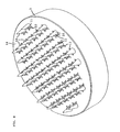
- Figure 1a shows a container 1 which may be a water permeable container according to EP-B-0 717 603. This has to be understood as an example only, all kinds and shapes of water permeable containers are possible, for example a cylindrical shape with permeable upper and lower faces or a cubic shape.
- the water permeable parts of the container are usually made of filter paper or the like and the container contains a dose of ground coffee, for example in an amount sufficient for preparing one cup of coffee.
- the coffee extract is then produced by pressing hot water through inlet openings 8 of the part 2 which water flows through the filter paper of the container 1, the ground coffee 7 and out of the chamber 5 through outlet openings 9 in the other part 3 which is provided with a multitude of openings 9 as in a filter plate, although the filtering is mainly done by the filter paper of the container resting against the surface 14 of the part 3 forming the inner extraction chamber wall.
- the coffee extract flowing out of outlets 9 is collected in a conduit, which finally ends above the cup. Water flows in this known way as long as the pump of the coffee machine is working and the pressure generated in the container depends mainly from the compactness of the coffee powder in the container and the number and diameter of the openings 9.
- elements 10 which enter into the container being in the extraction chamber and which provide extraction channels 11 reaching into the container (these channels are better visible in Figs. 2 and 4). Accordingly, the container is pierced by the elements 10, which makes it preferable to provide them with a conical or pyramidal shape or other shape allowing a piercing of the container wall without tearing it too much, so that the elements 10 are inserted in the container 1 without destroying the filter paper of the permeable container except for the piercing area.
- the elements 10 are shown in the examples as being solid with the part 3 and thus with the wall of the extraction chamber 5. This is a preferred embodiment which lead automatically to the piercing of the container as the parts 2, 3 move together to close the chamber 5. It is, however, possible as well to have separate elements 10 which are moved into the chamber 5 after the chamber has been closed, for example needle-like shaped or conical elements 10 that are inserted into the chamber 5 and thus into the container through openings in part 3 which may or may not be the outlet openings 9 at the same time. These outlet openings 9 may in this case be provided within the elements 10 as well.
- the piercing elements move in any case into the space of the chamber provided for the container and thus actively pierce this container before water is fed therein.
- FIG. 1 shows an enlarged part sectional view of part 3 and an element 10 with channel 11.
- This channel 11 may open directly in an outlet opening 9 or there may be provided as shown in Figures 2 and 4 channel sections 13 that are grooves in the surface 14 of the chamber wall or part 3, respectively.
- the outlet openings 9 may preferably be shaped as a nozzle as shown in Figure 2 or more generally as having a smaller diameter section along their length or may be straight openings.
- the nozzle shaped outlet openings 9 enhance this effect by making it possible to make the smallest opening diameters smaller than straight openings without excessive danger of clogging of the openings.
- Figure 4 which just shows the extraction surface 14 of the part 3 without the flange thereof for forming a closed chamber 5, shows again elements 10 with channels 11 and preferred grooves 13.
- elements 10 and the number of channels 11 and grooves 14 and their shapes are only to be understood as an example.
- FIG. 1c shows the closed extraction state of chamber 5, which would allow extraction as explained above, a preferred embodiment of the present invention is explained.
- the outlet openings 9 are blocked by a blocking element 16 which prevents flow of the water through the extraction chamber 5 and container 1. Since the pump is working and water can enter the chamber 5 through openings 8, the pressure in the chamber is raising depending on the power of the pump. A force A is acting on the blocking element 16, which counteracts the force of the coffee extract wanting to exit through outlet openings 9.
- the blocking means is removed, for example by reversing force A, and the outlet openings are opened so that coffee extract can flow out of the chamber and into the cup as explained above, as shown in Figure 1d.
- This blocking of the extraction chamber is preferably done at its outlet openings as shown, but it would as well be possible to arrange blocking means in flow direction nearer to the final outlet above the cup.
- the blocking of the extraction chamber enhances extraction pressure therein, which improves the perceived coffee extract quality.
- FIG 3 shows schematically the hydraulic circuit of a coffee machine according to an embodiment of the invention.
- the chamber 5 is shown in open state and in this schematic view without the elements 10 and the openings for water and extract. Parts 2 and 3 are shown and part 2 is fixed whereas part 3 is movable along directions B and C to open and close the chamber 5.
- a pump 20 sucks water from a tank 21 by conduit 22.
- the pump feeds water through conduit 23 to an electric heating element from which the water is fed via conduit 25 to the openings in wall 2 (not shown) into chamber 5 when it is in closed state.
- the pump feeds water on the other hand via line 25 and an electrically controlled valve 26 into a chamber 27.
- Valve 26 is at this time operated to let water pass by line 25 but no water passes through line 28, which can lead water back to the tank 21.
- the extraction unit 30, which bears at its one end the part 3 of the chamber 5 is moved in direction C to close the chamber 5 into which a container 1 (not shown) has been inserted beforehand. Accordingly, this container is enclosed in the chamber 5.
- the closing of the chamber 5 is provided by the water pressure in chamber 27 against the force of spring 31 (only schematically shown), so that this spring is compressed by the closing movement of extraction unit 30.
- Line 25 feeds as well the pressure sensitive switch valve 40 which at a pressure below a predetermined level directs water via line 33 to a chamber 35 while line 34 leading water back to the tank 21 remains closed.
- a piston 36 with the blocking plate 37 adapted to block the outlet openings 9 (not shown) in part 3 is moved forward in direction C in addition to the movement of the whole unit 30, so that the outlet openings are blocked.
- This movement of piston 36 acts against spring 38 (shown only schematically).
- the chamber 5 closes and the outlet openings thereof are closed. Meanwhile water is heated in heating element 24 and is then, after the closing of chamber and openings, fed to the chamber 5 by a controllable valve.
- valve 26 is controlled to connect line 25 to line 28, so that water from chamber 27 flows back into tank 21 which allows spring 31 to press back the extraction 30 unit in direction B which opens chamber 5 so that the container can be removed and disposed.
- the machine is then ready for a new extraction cycle as described.
- the pressure sensitive valve 40 is preferably a valve employing a piston fed by water under pump pressure, which piston is displaced by the water pressure against a spring. During a first travel period the piston allows connection of lines 25 and 33 and when a certain displacement is reached (depending on the water pressure) lines 33 and 34 are connected as explained.
- FIG. 5 shows a more detailed sectional view through parts of Figure 3 wherein same reference numerals designate same elements.
- lower part 3 of the extraction chamber 5 is shown with the extraction elements, which can be moved by pressure in chamber 27.
- chamber 35 for moving piston 36 with blocking surface 37 is shown.
- the collection means 42 lead the coffee extract towards spout 43 from where the extract is delivered to the cup.
Abstract
Description
- The invention relates to a coffee extraction system according to
claim 1 and to a coffee extraction method according toclaim 14. - It is known by example from EP-B-0 717 603, to enclose a dose of ground coffee in a water permeable container and to extract coffee therefrom in an extraction chamber by pressing hot water through the container. The water permeable container is usually made of coffee filter paper and therefore allows water to enter the container through the paper on one side and provides the coffee filtering means by itself on the other side.
- On the other hand different systems are known where ground coffee is enclosed in a closed, completely water impermeable container which has to be pierced on one side by water injection means and which bursts open on the other side by the pressure of the water in the container which acts on a container membrane. This bursting may be promoted by a filter plate having cone shaped elements resulting in local stress areas on the membrane stressed and bursted by the water pressure; such a system is for example known from EP-B-0 604 615. By US-A-2 899 886 and US-A-2 968 560 it is known to pierce water impermeable containers upon closing the extraction chamber.
- The object of the present invention is to improve on the coffee extract quality of the first kind of systems with water permeable containers.
- This object is met by the features of
claim 1. - Surprisingly, it has been found that a piercing of the water permeable container in the extraction chamber - which seems to be in contradiction to this system since the container is water permeable per se - and the providing of extraction channels gives a better defined extraction at higher pressures which results in a better perceived coffee extract quality. The claimed coffee machine of the system is provided with an extraction chamber and pierces the container in this chamber.
- Preferably the extraction elements are provided on the surface on the chamber wall, so that upon closing of the chamber to enclose the container is automatically pierced and the channels are provided. In an alternative embodiment, the extraction elements can be introduced into the chamber separately and are thus designed to be introduced movably through the chamber wall or walls.
- According to a preferred embodiment of the invention the water and coffee extract is prevented from leaving the extraction chamber until a predetermined pressure has been reached in this chamber. This avoids a mere percolating of the water through the container and puts the coffee under the sought for water pressure for a certain, well-defined time, which has heretofore not been the case.
- The object is further met by the extraction method of
claim 14. - In the following preferred embodiments are described as examples with reference to the drawings wherein
- Figures 1a to 1d show a general schematic overview on the extraction steps;
- Figure 2 shows a sectional view of a part of the extraction chamber and the container;
- Figure 3 shows a general overview on the hydraulic system of a coffee machine according to the invention;
- Figure 4 shows a perspective view of an inner surface of the extraction chamber; and
- Figure 5 shows more detailed a sectional view through the one extraction chamber part and the driving pistons for closing the chamber and blocking fluid flow therethrough.
-
- Figures 1a to 1d show in a very general way the extraction of coffee according to the aspects of the invention. Figure 1a shows a
container 1 which may be a water permeable container according to EP-B-0 717 603. This has to be understood as an example only, all kinds and shapes of water permeable containers are possible, for example a cylindrical shape with permeable upper and lower faces or a cubic shape. The water permeable parts of the container are usually made of filter paper or the like and the container contains a dose of ground coffee, for example in an amount sufficient for preparing one cup of coffee. - For producing the coffee extract from the ground coffee contained in the
container 1, it is known, and is the case in the present invention as well, to insert this container into an extraction chamber 5, which can be done manually or by automatic feeding means depending on the actual type of coffee machine. For insertion of thecontainer 1 the extraction chamber is in an open state as shown in Figure 1b. It is known to then close the extraction chamber which is adapted in its shape, to the type of container used, and specifically to its shape so that the container is enclosed by the extraction chamber. Enclosed in the context of the present invention means that the container is in a closed chamber more or less held tightly therein. It is possible that flanges or a flange 4 of the container are thereby pinched between twoparts inlet openings 8 of thepart 2 which water flows through the filter paper of thecontainer 1, the ground coffee 7 and out of the chamber 5 throughoutlet openings 9 in theother part 3 which is provided with a multitude ofopenings 9 as in a filter plate, although the filtering is mainly done by the filter paper of the container resting against thesurface 14 of thepart 3 forming the inner extraction chamber wall. The coffee extract flowing out ofoutlets 9 is collected in a conduit, which finally ends above the cup. Water flows in this known way as long as the pump of the coffee machine is working and the pressure generated in the container depends mainly from the compactness of the coffee powder in the container and the number and diameter of theopenings 9. - According to one aspect of the invention and still with reference to Figs. 1a to 1d, there are provided
elements 10 which enter into the container being in the extraction chamber and which provideextraction channels 11 reaching into the container (these channels are better visible in Figs. 2 and 4). Accordingly, the container is pierced by theelements 10, which makes it preferable to provide them with a conical or pyramidal shape or other shape allowing a piercing of the container wall without tearing it too much, so that theelements 10 are inserted in thecontainer 1 without destroying the filter paper of the permeable container except for the piercing area. - The
elements 10 are shown in the examples as being solid with thepart 3 and thus with the wall of the extraction chamber 5. This is a preferred embodiment which lead automatically to the piercing of the container as theparts separate elements 10 which are moved into the chamber 5 after the chamber has been closed, for example needle-like shaped orconical elements 10 that are inserted into the chamber 5 and thus into the container through openings inpart 3 which may or may not be theoutlet openings 9 at the same time. Theseoutlet openings 9 may in this case be provided within theelements 10 as well. The piercing elements move in any case into the space of the chamber provided for the container and thus actively pierce this container before water is fed therein. - The water is pressed through the
openings 8 ofpart 2 and enters thecontainer 1 through its permeable paper wall. The coffee extract on the other hand leaves thecontainer 1 mainly bychannels 11 being in connection withoutlet openings 9. Figure 2 shows an enlarged part sectional view ofpart 3 and anelement 10 withchannel 11. Thischannel 11 may open directly in an outlet opening 9 or there may be provided as shown in Figures 2 and 4channel sections 13 that are grooves in thesurface 14 of the chamber wall orpart 3, respectively. Theoutlet openings 9 may preferably be shaped as a nozzle as shown in Figure 2 or more generally as having a smaller diameter section along their length or may be straight openings. - By providing
defined channels 11 and preferably 13, a more even and predictable flow of water is resulting and the pressure generated in the chamber 5 andcontainer 1, respectively, is greater and better defined as in the prior art coffee machines, extraction systems and methods, which results in a better and from dose to dose more uniform coffee extract quality. - The nozzle shaped
outlet openings 9 enhance this effect by making it possible to make the smallest opening diameters smaller than straight openings without excessive danger of clogging of the openings. - Figure 4, which just shows the
extraction surface 14 of thepart 3 without the flange thereof for forming a closed chamber 5, shows againelements 10 withchannels 11 andpreferred grooves 13. Of course, the number ofelements 10 and the number ofchannels 11 andgrooves 14 and their shapes are only to be understood as an example. - With reference to Figure 1c which shows the closed extraction state of chamber 5, which would allow extraction as explained above, a preferred embodiment of the present invention is explained. As can be seen in Figure 1c, the
outlet openings 9 are blocked by a blockingelement 16 which prevents flow of the water through the extraction chamber 5 andcontainer 1. Since the pump is working and water can enter the chamber 5 throughopenings 8, the pressure in the chamber is raising depending on the power of the pump. A force A is acting on the blockingelement 16, which counteracts the force of the coffee extract wanting to exit throughoutlet openings 9. As soon as the pressure build up by the pump has reached a predetermined level, the blocking means is removed, for example by reversing force A, and the outlet openings are opened so that coffee extract can flow out of the chamber and into the cup as explained above, as shown in Figure 1d. - This blocking of the extraction chamber is preferably done at its outlet openings as shown, but it would as well be possible to arrange blocking means in flow direction nearer to the final outlet above the cup.
- The blocking of the extraction chamber enhances extraction pressure therein, which improves the perceived coffee extract quality.
- With reference to Figures 3 and 5 the coffee machine and coffee extracting system and method are now explained more in detail. Figure 3 shows schematically the hydraulic circuit of a coffee machine according to an embodiment of the invention. The chamber 5 is shown in open state and in this schematic view without the
elements 10 and the openings for water and extract.Parts part 2 is fixed whereaspart 3 is movable along directions B and C to open and close the chamber 5. Apump 20 sucks water from atank 21 byconduit 22. The pump feeds water throughconduit 23 to an electric heating element from which the water is fed viaconduit 25 to the openings in wall 2 (not shown) into chamber 5 when it is in closed state. The pump feeds water on the other hand vialine 25 and an electrically controlledvalve 26 into achamber 27. Valve 26 is at this time operated to let water pass byline 25 but no water passes throughline 28, which can lead water back to thetank 21. When water under pressure enterschamber 27, theextraction unit 30, which bears at its one end thepart 3 of the chamber 5 is moved in direction C to close the chamber 5 into which a container 1 (not shown) has been inserted beforehand. Accordingly, this container is enclosed in the chamber 5. The closing of the chamber 5 is provided by the water pressure inchamber 27 against the force of spring 31 (only schematically shown), so that this spring is compressed by the closing movement ofextraction unit 30.Line 25 feeds as well the pressuresensitive switch valve 40 which at a pressure below a predetermined level directs water vialine 33 to achamber 35 whileline 34 leading water back to thetank 21 remains closed. By the water pressure in chamber 35 apiston 36 with the blockingplate 37 adapted to block the outlet openings 9 (not shown) inpart 3 is moved forward in direction C in addition to the movement of thewhole unit 30, so that the outlet openings are blocked. This movement ofpiston 36 acts against spring 38 (shown only schematically). - Accordingly, when the pump starts working and the water flow is enabled as described, the chamber 5 closes and the outlet openings thereof are closed. Meanwhile water is heated in
heating element 24 and is then, after the closing of chamber and openings, fed to the chamber 5 by a controllable valve. - Pressure in the lines and in chamber 5 raises. As soon as the pressure reaches a level that corresponds to the
predetermined switch valve 40 pressure level, thisvalve 40 deconnects line 33 fromline 25 and connectsline 33 withline 34, so that the water inchamber 35 will flow back intotank 21 thereby allowingpiston 36 with blockingsurface 37 to move back by spring force ofspring 38 in direction B, thereby opening outlet openings 9 (not shown) which allows the flow of coffee extract from chamber 5 (still closed) into a collecting conduit (not shown) and into the cup. When the predetermined amount of water has thus flown through chamber 5 and the container, further water flow is stopped by stopping the pump to avoid overfilling of the cup. Since the extraction is now complete, thevalve 26 is controlled to connectline 25 toline 28, so that water fromchamber 27 flows back intotank 21 which allowsspring 31 to press back theextraction 30 unit in direction B which opens chamber 5 so that the container can be removed and disposed. The machine is then ready for a new extraction cycle as described. - The pressure
sensitive valve 40 is preferably a valve employing a piston fed by water under pump pressure, which piston is displaced by the water pressure against a spring. During a first travel period the piston allows connection oflines lines - Figure 5 shows a more detailed sectional view through parts of Figure 3 wherein same reference numerals designate same elements. In particular
lower part 3 of the extraction chamber 5 is shown with the extraction elements, which can be moved by pressure inchamber 27. As wellchamber 35 for movingpiston 36 with blockingsurface 37 is shown. The collection means 42 lead the coffee extract towardsspout 43 from where the extract is delivered to the cup.
Claims (15)
- A coffee extraction system comprising a coffee machine and at least partly water permeable containers containing a dose of ground coffee, wherein the coffee machine is adapted to enclose a container by an extraction chamber characterised in that it is further adapted to pierce the container while enclosing it and to provide extraction channels reaching into the container.
- A coffee extraction system according to claim 1 wherein the extraction chamber forms a water-thight enclosure around said container except for said extraction channels and water feeding means for feeding water into said container.
- A coffee extraction system according to claim 1 wherein the containers have walls made of filter paper.
- A coffee extraction system according to one of claims 1 to 3, wherein the coffee machine comprises water heating means, a pump, a coffee extract outlet and the extraction chamber (5) being adapted for taking up the container in an open inserting state of the chamber and enclosing it in a closed extraction state of the chamber, the extraction chamber being connected on the one hand to the heating means and the pump so that hot water under pressure can enter the extraction chamber through openings (8) in a first wall (2) thereof, said extraction chamber being connected on the other hand to the coffee extract outlet by openings (9) in a second chamber wall (3), and wherein several extraction elements are provided that reach in closed extraction state of the chamber into the chamber such that a container is pierced by the elements and the extraction channels are provided reaching on the one hand into the container space of the extraction chamber and being connected on the other hand to the openings of the second wall.
- A coffee extraction system according to claim 4 wherein the extraction elements form part of the second chamber wall or wherein the extraction elements are separate, movable elements.
- A coffee extraction system according to claim 4, wherein the extraction elements each form two or more channels being in connection with one or more of the openings.
- A coffee extraction system according to any of claims 1 to 6 wherein the extraction channels further comprise grooves in the second chamber wall surface adjacent the elements.
- A coffee extraction system according to any of claims 1 to 7, wherein the openings in the second chamber wall are nozzle-shaped.
- A coffee extraction system according to any of claims 1 to 8 wherein the extraction chamber is closed and preferably the extraction elements are introduced into the container by a first water pressure operatable piston.
- A coffee extraction system according to claim 1, characterized by controllable blocking means for preventing coffee extract flow from the extraction chamber or the coffee extract outlet until a predetermined water pressure has been reached in the coffee machine.
- A coffee extraction system according to claim 10 wherein said blocking means blocks the outlet of the openings in the second chamber wall.
- A coffee extraction system according to claim 10 or 11 wherein the blocking means are controlled by a second water operatable piston.
- A coffee extraction system according to claim 12 wherein the second piston is controlled by a pressure sensitive valve relieving water pressure from the second piston when a predetermined pump pressure has been reached.
- A method for producing coffee extract from an at least partly water permeable container containing pre-dosed ground coffee using a coffee extraction system according to claim 1 wherein the container is pierced in an extraction chamber surrounding the container by elements reaching into the container and providing extraction channels.
- A method for producing coffee extract according to claim 14, wherein the outlet of coffee extract from the chamber is blocked by a controllable blocking means until the water pressure in the extraction chamber has reached a predetermined level.
Priority Applications (4)
| Application Number | Priority Date | Filing Date | Title |
|---|---|---|---|
| DE60111920T DE60111920T2 (en) | 2001-04-05 | 2001-04-05 | Kaffeeextrahierungssystem |
| EP01107800A EP1247480B1 (en) | 2001-04-05 | 2001-04-05 | Coffee extraction system |
| AT01107800T ATE299348T1 (en) | 2001-04-05 | 2001-04-05 | COFFEE EXTRACTION SYSTEM |
| DK01107800T DK1247480T3 (en) | 2001-04-05 | 2001-04-05 | coffee extraction |
Applications Claiming Priority (1)
| Application Number | Priority Date | Filing Date | Title |
|---|---|---|---|
| EP01107800A EP1247480B1 (en) | 2001-04-05 | 2001-04-05 | Coffee extraction system |
Publications (2)
| Publication Number | Publication Date |
|---|---|
| EP1247480A1 EP1247480A1 (en) | 2002-10-09 |
| EP1247480B1 true EP1247480B1 (en) | 2005-07-13 |
Family
ID=8176981
Family Applications (1)
| Application Number | Title | Priority Date | Filing Date |
|---|---|---|---|
| EP01107800A Expired - Lifetime EP1247480B1 (en) | 2001-04-05 | 2001-04-05 | Coffee extraction system |
Country Status (4)
| Country | Link |
|---|---|
| EP (1) | EP1247480B1 (en) |
| AT (1) | ATE299348T1 (en) |
| DE (1) | DE60111920T2 (en) |
| DK (1) | DK1247480T3 (en) |
Cited By (6)
| Publication number | Priority date | Publication date | Assignee | Title |
|---|---|---|---|---|
| USD637484S1 (en) | 2010-09-02 | 2011-05-10 | Keurig, Incorporated | Beverage cartridge |
| USD647399S1 (en) | 2010-09-02 | 2011-10-25 | Keurig, Incorporated | Beverage cartridge |
| USD647398S1 (en) | 2010-09-02 | 2011-10-25 | Keurig Incorporated | Beverage cartridge |
| US8361527B2 (en) | 2010-09-02 | 2013-01-29 | Keurig, Incorporated | Beverage cartridge |
| EP3730007A1 (en) | 2019-03-22 | 2020-10-28 | SAGA COFFEE S.p.A. | Brewing device for producing a beverage from a single-serve capsule |
| IT201900013458A1 (en) | 2019-07-31 | 2021-01-31 | Saga Coffee S P A | INFUSER DEVICE FOR THE PREPARATION OF DRINKS FROM DISPOSABLE CAPSULES |
Families Citing this family (20)
| Publication number | Priority date | Publication date | Assignee | Title |
|---|---|---|---|---|
| US7640843B2 (en) | 2003-01-24 | 2010-01-05 | Kraft Foods R & D, Inc. | Cartridge and method for the preparation of beverages |
| ES2315665T3 (en) * | 2003-08-05 | 2009-04-01 | Gaillard, Jean-Paul | DEVICE FOR THE PREPARATION OF A COFFEE DRINK. |
| DE602004028375D1 (en) * | 2003-08-18 | 2010-09-09 | Koninkl Philips Electronics Nv | BEVERAGE MANUFACTURER WITH ADVANCES ON THE UPPER WALL OF THE INFUSION CHAMBER |
| EP1704803A1 (en) * | 2005-03-22 | 2006-09-27 | Tuttoespresso S.p.a. | Beverage cartridge and system |
| ITMO20070241A1 (en) * | 2007-07-20 | 2009-01-21 | Saeco Ipr Ltd | DEVICE FOR DRILLING PORTIONED CAPS |
| WO2010137955A1 (en) * | 2009-06-17 | 2010-12-02 | Sara Lee/De N.V. | System, apparatus and method for preparing a beverage |
| ITMI20091633A1 (en) * | 2009-09-24 | 2011-03-25 | Brasilia Spa | START-UP DEVICE FOR AN AROMATIC DRINK PRODUCTION MACHINE |
| CA2776298C (en) * | 2009-10-05 | 2017-08-22 | Nestec S.A. | Cartridge extraction device |
| AU2010326758B2 (en) * | 2009-12-01 | 2014-09-18 | Nestec S.A. | Cartridge extraction device |
| FR2960400B1 (en) * | 2010-05-25 | 2013-01-18 | Cie Mediterraneenne Des Cafes | BEVERAGE INFUSION MACHINE |
| WO2012083743A1 (en) * | 2010-12-24 | 2012-06-28 | 中山市诚泰金属有限公司 | Filter screen, manufacturing method of filter screen, and coffee maker applying filter screen |
| ITRM20110329A1 (en) * | 2011-06-23 | 2012-12-24 | Gardosi Massimiliano | COMPENSATOR FOR APPLIANCES HOT SPREADERS, PREFERABLY PRE-DOSED, IN PARTICULAR FOR PODS COFFEE MACHINES. |
| WO2013114294A1 (en) * | 2012-01-30 | 2013-08-08 | Ethical Coffee Company Sa | Movable puncture needle for a device for preparing a beverage extracted from a capsule |
| US10004248B2 (en) | 2012-07-06 | 2018-06-26 | Conopco, Inc. | Package recognition system |
| CA3093758A1 (en) * | 2018-03-14 | 2019-09-19 | Societe Des Produits Nestle S.A. | Beverage extraction unit with movable outflow obstructor |
| WO2019175228A1 (en) * | 2018-03-14 | 2019-09-19 | Societe Des Produits Nestle S.A. | Beverage machine with a controlled outflow aperture |
| CN111770710B (en) * | 2018-03-14 | 2023-11-28 | 雀巢产品有限公司 | Beverage machine with partially closed dispensing face |
| NL2022165B1 (en) * | 2018-12-10 | 2020-07-02 | Douwe Egberts Bv | Dispensing module for a beverage preparation machine |
| EP3735873A1 (en) * | 2019-05-06 | 2020-11-11 | Koninklijke Philips N.V. | An apparatus for releasing an ingredient from a capsule |
| DE102021123553A1 (en) | 2021-09-10 | 2023-03-16 | Eugster / Frismag Ag | Brewing unit with hydraulic infusion means and method of operating such a brewing unit |
Family Cites Families (7)
| Publication number | Priority date | Publication date | Assignee | Title |
|---|---|---|---|---|
| US2968560A (en) * | 1959-02-06 | 1961-01-17 | Sealpak Corp | Infusion package for producing a coffee beverage |
| US5897899A (en) * | 1991-05-08 | 1999-04-27 | Nestec S.A. | Cartridges containing substances for beverage preparation |
| KR100303614B1 (en) | 1992-07-20 | 2001-11-22 | 뷜르 로망 엘. | Extraction method of sealed flexible bag and apparatus thereof |
| EP0622039A1 (en) * | 1993-04-27 | 1994-11-02 | ESSEGIELLE S.r.l | Percolator cup for espresso coffee machines |
| FR2709655B1 (en) | 1993-09-06 | 1995-11-24 | Cafes Cie Mediterraneenne | Express coffee machine using ground coffee packaging of the pre-dosed tablet type. |
| CH689753A5 (en) * | 1995-02-08 | 1999-10-15 | Lough J Ltd | Process for the preparation of a coffee-type beverage expressed and device for its implementation. |
| EP1016364A3 (en) * | 1998-12-18 | 2000-11-02 | Antica Torref. del Borgo Bardassano snc di Boido Aldo e C. | Device and process for the formation of cream, usable on machines for the preparation of infusions, in particular coffee |
-
2001
- 2001-04-05 DE DE60111920T patent/DE60111920T2/en not_active Expired - Lifetime
- 2001-04-05 AT AT01107800T patent/ATE299348T1/en active
- 2001-04-05 EP EP01107800A patent/EP1247480B1/en not_active Expired - Lifetime
- 2001-04-05 DK DK01107800T patent/DK1247480T3/en active
Cited By (7)
| Publication number | Priority date | Publication date | Assignee | Title |
|---|---|---|---|---|
| USD637484S1 (en) | 2010-09-02 | 2011-05-10 | Keurig, Incorporated | Beverage cartridge |
| USD647399S1 (en) | 2010-09-02 | 2011-10-25 | Keurig, Incorporated | Beverage cartridge |
| USD647398S1 (en) | 2010-09-02 | 2011-10-25 | Keurig Incorporated | Beverage cartridge |
| US8361527B2 (en) | 2010-09-02 | 2013-01-29 | Keurig, Incorporated | Beverage cartridge |
| US9555957B2 (en) | 2010-09-02 | 2017-01-31 | Keurig Green Mountain, Inc. | Beverage cartridge |
| EP3730007A1 (en) | 2019-03-22 | 2020-10-28 | SAGA COFFEE S.p.A. | Brewing device for producing a beverage from a single-serve capsule |
| IT201900013458A1 (en) | 2019-07-31 | 2021-01-31 | Saga Coffee S P A | INFUSER DEVICE FOR THE PREPARATION OF DRINKS FROM DISPOSABLE CAPSULES |
Also Published As
| Publication number | Publication date |
|---|---|
| DK1247480T3 (en) | 2005-10-24 |
| ATE299348T1 (en) | 2005-07-15 |
| EP1247480A1 (en) | 2002-10-09 |
| DE60111920T2 (en) | 2006-01-12 |
| DE60111920D1 (en) | 2005-08-18 |
Similar Documents
| Publication | Publication Date | Title |
|---|---|---|
| EP1247480B1 (en) | Coffee extraction system | |
| RU2349244C2 (en) | Production method of capsule beverage and device for method performing | |
| JP5073684B2 (en) | Beverage ingredient capsule | |
| EP1554958B1 (en) | Coffee machine for brewing ground coffee packed in a cartridge | |
| KR101367552B1 (en) | Method for preparing a beverage from a capsule | |
| JPH067251A (en) | Method and device for preparing coffee drink | |
| CA2677495C (en) | Brewing apparatus with a drainage valve | |
| CN100493428C (en) | A beverage-making device comprising a brewing chamber and pressure release means | |
| JP2006142015A (en) | Hot beverage making machine for cooking and extracting substance contained in cartridge | |
| CN104244779A (en) | Coffee maker and method for operating same | |
| JP2013514852A (en) | Beverage infusion unit with hydraulic closure system | |
| EP1961351A2 (en) | Heating element of a drink preparation device | |
| US4505191A (en) | Dispensing unit for espresso coffee machines | |
| DE202005021174U1 (en) | Beverage machine, has stock chamber bottom part moved together with capsule during closing of chamber, where capsule cover is lanced by lancing unit, when capsule base is deformed by another lancing unit towards capsule cover | |
| DE102011102733A1 (en) | Apparatus and method for preparing a cold beverage | |
| EP2881016B1 (en) | Electric coffee machine with easier pressing of wet grounds | |
| US11045037B2 (en) | Brewing unit, machine and system for the preparation of a beverage using prepackaged capsules | |
| EP2862486B1 (en) | Dispenser unit for an espresso coffee machine of capsule type, for professional use | |
| EP3764853B1 (en) | Beverage extraction unit for selectively providing orifices of different types in a capsule for extraction of the beverage | |
| EP3763257A1 (en) | Brewing unit for a beverage maker and beverage maker | |
| EP1625815B1 (en) | Apparatus and method for filling and emtying a brewing chaber | |
| KR200245702Y1 (en) | device for oil guide in oil press | |
| KR100308371B1 (en) | an oil press |
Legal Events
| Date | Code | Title | Description |
|---|---|---|---|
| PUAI | Public reference made under article 153(3) epc to a published international application that has entered the european phase |
Free format text: ORIGINAL CODE: 0009012 |
|
| AK | Designated contracting states |
Kind code of ref document: A1 Designated state(s): AT BE CH CY DE DK ES FI FR GB GR IE IT LI LU MC NL PT SE TR |
|
| AX | Request for extension of the european patent |
Free format text: AL;LT;LV;MK;RO;SI |
|
| 17P | Request for examination filed |
Effective date: 20030324 |
|
| AKX | Designation fees paid |
Designated state(s): AT BE CH CY DE DK ES FI FR GB GR IE IT LI LU MC NL PT SE TR |
|
| 17Q | First examination report despatched |
Effective date: 20030728 |
|
| GRAP | Despatch of communication of intention to grant a patent |
Free format text: ORIGINAL CODE: EPIDOSNIGR1 |
|
| GRAS | Grant fee paid |
Free format text: ORIGINAL CODE: EPIDOSNIGR3 |
|
| GRAA | (expected) grant |
Free format text: ORIGINAL CODE: 0009210 |
|
| AK | Designated contracting states |
Kind code of ref document: B1 Designated state(s): AT BE CH CY DE DK ES FI FR GB GR IE IT LI LU MC NL PT SE TR |
|
| PG25 | Lapsed in a contracting state [announced via postgrant information from national office to epo] |
Ref country code: TR Free format text: LAPSE BECAUSE OF FAILURE TO SUBMIT A TRANSLATION OF THE DESCRIPTION OR TO PAY THE FEE WITHIN THE PRESCRIBED TIME-LIMIT Effective date: 20050713 Ref country code: FI Free format text: LAPSE BECAUSE OF FAILURE TO SUBMIT A TRANSLATION OF THE DESCRIPTION OR TO PAY THE FEE WITHIN THE PRESCRIBED TIME-LIMIT Effective date: 20050713 |
|
| REG | Reference to a national code |
Ref country code: GB Ref legal event code: FG4D |
|
| REG | Reference to a national code |
Ref country code: CH Ref legal event code: EP Ref country code: CH Ref legal event code: NV Representative=s name: E. BLUM & CO. PATENTANWAELTE |
|
| REG | Reference to a national code |
Ref country code: IE Ref legal event code: FG4D |
|
| REF | Corresponds to: |
Ref document number: 60111920 Country of ref document: DE Date of ref document: 20050818 Kind code of ref document: P |
|
| PG25 | Lapsed in a contracting state [announced via postgrant information from national office to epo] |
Ref country code: SE Free format text: LAPSE BECAUSE OF FAILURE TO SUBMIT A TRANSLATION OF THE DESCRIPTION OR TO PAY THE FEE WITHIN THE PRESCRIBED TIME-LIMIT Effective date: 20051013 Ref country code: GR Free format text: LAPSE BECAUSE OF FAILURE TO SUBMIT A TRANSLATION OF THE DESCRIPTION OR TO PAY THE FEE WITHIN THE PRESCRIBED TIME-LIMIT Effective date: 20051013 |
|
| REG | Reference to a national code |
Ref country code: DK Ref legal event code: T3 |
|
| PG25 | Lapsed in a contracting state [announced via postgrant information from national office to epo] |
Ref country code: PT Free format text: LAPSE BECAUSE OF FAILURE TO SUBMIT A TRANSLATION OF THE DESCRIPTION OR TO PAY THE FEE WITHIN THE PRESCRIBED TIME-LIMIT Effective date: 20051219 |
|
| PG25 | Lapsed in a contracting state [announced via postgrant information from national office to epo] |
Ref country code: GB Free format text: LAPSE BECAUSE OF NON-PAYMENT OF DUE FEES Effective date: 20060405 Ref country code: IE Free format text: LAPSE BECAUSE OF NON-PAYMENT OF DUE FEES Effective date: 20060405 |
|
| ET | Fr: translation filed | ||
| PG25 | Lapsed in a contracting state [announced via postgrant information from national office to epo] |
Ref country code: MC Free format text: LAPSE BECAUSE OF NON-PAYMENT OF DUE FEES Effective date: 20060430 |
|
| PGFP | Annual fee paid to national office [announced via postgrant information from national office to epo] |
Ref country code: IT Payment date: 20060430 Year of fee payment: 6 |
|
| PG25 | Lapsed in a contracting state [announced via postgrant information from national office to epo] |
Ref country code: DK Free format text: LAPSE BECAUSE OF NON-PAYMENT OF DUE FEES Effective date: 20060501 |
|
| PLBE | No opposition filed within time limit |
Free format text: ORIGINAL CODE: 0009261 |
|
| STAA | Information on the status of an ep patent application or granted ep patent |
Free format text: STATUS: NO OPPOSITION FILED WITHIN TIME LIMIT |
|
| 26N | No opposition filed |
Effective date: 20060418 |
|
| REG | Reference to a national code |
Ref country code: DK Ref legal event code: EBP |
|
| GBPC | Gb: european patent ceased through non-payment of renewal fee |
Effective date: 20060405 |
|
| REG | Reference to a national code |
Ref country code: IE Ref legal event code: MM4A |
|
| REG | Reference to a national code |
Ref country code: FR Ref legal event code: ST Effective date: 20061230 |
|
| REG | Reference to a national code |
Ref country code: CH Ref legal event code: PFA Owner name: MOEVENPICK - HOLDING Free format text: MOEVENPICK - HOLDING#SINSERSTRASSE 47#6330 CHAM (CH) -TRANSFER TO- MOEVENPICK - HOLDING#SINSERSTRASSE 47#6330 CHAM (CH) |
|
| PG25 | Lapsed in a contracting state [announced via postgrant information from national office to epo] |
Ref country code: FR Free format text: LAPSE BECAUSE OF NON-PAYMENT OF DUE FEES Effective date: 20060502 |
|
| PG25 | Lapsed in a contracting state [announced via postgrant information from national office to epo] |
Ref country code: CY Free format text: LAPSE BECAUSE OF FAILURE TO SUBMIT A TRANSLATION OF THE DESCRIPTION OR TO PAY THE FEE WITHIN THE PRESCRIBED TIME-LIMIT Effective date: 20050713 |
|
| PG25 | Lapsed in a contracting state [announced via postgrant information from national office to epo] |
Ref country code: ES Free format text: LAPSE BECAUSE OF NON-PAYMENT OF DUE FEES Effective date: 20060430 |
|
| PG25 | Lapsed in a contracting state [announced via postgrant information from national office to epo] |
Ref country code: IT Free format text: LAPSE BECAUSE OF NON-PAYMENT OF DUE FEES Effective date: 20070405 |
|
| PGFP | Annual fee paid to national office [announced via postgrant information from national office to epo] |
Ref country code: NL Payment date: 20120413 Year of fee payment: 12 Ref country code: BE Payment date: 20120412 Year of fee payment: 12 Ref country code: DE Payment date: 20120419 Year of fee payment: 12 Ref country code: CH Payment date: 20120412 Year of fee payment: 12 Ref country code: LU Payment date: 20120426 Year of fee payment: 12 |
|
| PGFP | Annual fee paid to national office [announced via postgrant information from national office to epo] |
Ref country code: AT Payment date: 20120327 Year of fee payment: 12 |
|
| BERE | Be: lapsed |
Owner name: *MOVENPICK - HOLDING Effective date: 20130430 |
|
| REG | Reference to a national code |
Ref country code: NL Ref legal event code: V1 Effective date: 20131101 |
|
| REG | Reference to a national code |
Ref country code: CH Ref legal event code: PL |
|
| REG | Reference to a national code |
Ref country code: AT Ref legal event code: MM01 Ref document number: 299348 Country of ref document: AT Kind code of ref document: T Effective date: 20130430 |
|
| PG25 | Lapsed in a contracting state [announced via postgrant information from national office to epo] |
Ref country code: CH Free format text: LAPSE BECAUSE OF NON-PAYMENT OF DUE FEES Effective date: 20130430 Ref country code: DE Free format text: LAPSE BECAUSE OF NON-PAYMENT OF DUE FEES Effective date: 20131101 Ref country code: LI Free format text: LAPSE BECAUSE OF NON-PAYMENT OF DUE FEES Effective date: 20130430 Ref country code: BE Free format text: LAPSE BECAUSE OF NON-PAYMENT OF DUE FEES Effective date: 20130430 Ref country code: AT Free format text: LAPSE BECAUSE OF NON-PAYMENT OF DUE FEES Effective date: 20130430 |
|
| REG | Reference to a national code |
Ref country code: DE Ref legal event code: R119 Ref document number: 60111920 Country of ref document: DE Effective date: 20131101 |
|
| PG25 | Lapsed in a contracting state [announced via postgrant information from national office to epo] |
Ref country code: NL Free format text: LAPSE BECAUSE OF NON-PAYMENT OF DUE FEES Effective date: 20131101 |
|
| PG25 | Lapsed in a contracting state [announced via postgrant information from national office to epo] |
Ref country code: LU Free format text: LAPSE BECAUSE OF NON-PAYMENT OF DUE FEES Effective date: 20130405 |
|
| REG | Reference to a national code |
Ref country code: DE Ref legal event code: R082 Ref document number: 60111920 Country of ref document: DE Representative=s name: FRIESE GOEDEN PATENTANWAELTE PARTGMBB, DE |
|
| REG | Reference to a national code |
Ref country code: DE Ref legal event code: R082 Ref document number: 60111920 Country of ref document: DE Representative=s name: FRIESE GOEDEN PATENTANWAELTE PARTGMBB, DE |