EP1247417B1 - Method for preparing an interfrequency handover, a network element and a mobile station - Google Patents
Method for preparing an interfrequency handover, a network element and a mobile station Download PDFInfo
- Publication number
- EP1247417B1 EP1247417B1 EP01901229A EP01901229A EP1247417B1 EP 1247417 B1 EP1247417 B1 EP 1247417B1 EP 01901229 A EP01901229 A EP 01901229A EP 01901229 A EP01901229 A EP 01901229A EP 1247417 B1 EP1247417 B1 EP 1247417B1
- Authority
- EP
- European Patent Office
- Prior art keywords
- transmission
- duration
- transmission gap
- data
- gap
- Prior art date
- Legal status (The legal status is an assumption and is not a legal conclusion. Google has not performed a legal analysis and makes no representation as to the accuracy of the status listed.)
- Expired - Lifetime
Links
Images


Classifications
-
- H—ELECTRICITY
- H04—ELECTRIC COMMUNICATION TECHNIQUE
- H04W—WIRELESS COMMUNICATION NETWORKS
- H04W36/00—Hand-off or reselection arrangements
- H04W36/06—Reselecting a communication resource in the serving access point
-
- H—ELECTRICITY
- H04—ELECTRIC COMMUNICATION TECHNIQUE
- H04W—WIRELESS COMMUNICATION NETWORKS
- H04W36/00—Hand-off or reselection arrangements
- H04W36/0005—Control or signalling for completing the hand-off
- H04W36/0083—Determination of parameters used for hand-off, e.g. generation or modification of neighbour cell lists
- H04W36/0085—Hand-off measurements
- H04W36/0088—Scheduling hand-off measurements
-
- H—ELECTRICITY
- H04—ELECTRIC COMMUNICATION TECHNIQUE
- H04W—WIRELESS COMMUNICATION NETWORKS
- H04W52/00—Power management, e.g. TPC [Transmission Power Control], power saving or power classes
- H04W52/04—TPC
- H04W52/38—TPC being performed in particular situations
- H04W52/44—TPC being performed in particular situations in connection with interruption of transmission
-
- H—ELECTRICITY
- H04—ELECTRIC COMMUNICATION TECHNIQUE
- H04W—WIRELESS COMMUNICATION NETWORKS
- H04W56/00—Synchronisation arrangements
Landscapes
- Engineering & Computer Science (AREA)
- Computer Networks & Wireless Communication (AREA)
- Signal Processing (AREA)
- Mobile Radio Communication Systems (AREA)
- Time-Division Multiplex Systems (AREA)
Abstract
Description
- The invention relates in general to handovers in cellular networks. In particular it relates to transmitting data on one frequency and performing measurements on another frequency during or for an interfrequency handover.
- In cellular networks, where the communication connections are separated from each other using code division multiple access (CDMA) technique, a mobile station having an active communication connection with the cellular network should be able to receive data at the radio frequency related to that communication connection practically all the time. In an interfrequency handover the frequency on which an active communication connection exists is changed. A cell change may accompany the interfrequency handover, in which case the maneuver is an intercell-interfrequency handover, or the frequency change may take place within a single cell meaning that an intracell-interfrequency handover is performed. The present invention is equally applicable to all interfrequency handover types. During an interfrequency handover, a mobile station should be able to receive data on the first frequency and simultaneously to perform measurements and/or receive data on a second frequency.
- A mobile station, which has two receivers, may simultaneously listen to two frequencies. For allowing a mobile station, which has only one receiver, to receive data related to the active communication connection uninterruptedly on a first frequency and to receive data also on a second frequency, transmission gaps can be left to the radio transmission on the first frequency. During the transmission gaps, no data is transmitted to the mobile station using the first frequency. Compressed mode transmission refers to a transmitting data in such a way there are breaks (transmission gaps) in the transmission.
- Usually data to be transmitted over a radio interface is processed in such a way that the actually transmitted data has more redundancy than the original data. This way it is possible, for example, to detect transmission errors and to recover from them. Especially when the data to be transmitted is related to a real-time application, it may be desirable to transmit the user data at an unchanged data rate even during a compressed mode transmission. In this case a compromise usually has to be made for ensuring, on the one hand, the quality of the transmitted data and, on the other hand, enough time for listening to radio transmission on a second frequency.
- Typically data is transmitted over the radio interface in frames, which have a certain number of time slots. The time slots comprise a certain number of symbols. The number of time slots in a frame, the number of symbols in a time slot and the duration of a symbol are usually defined in the applicable cellular system specifications. For example, the Universal Terrestrial Radio Access network (UTRA) of the Universal Mobile Telecommunication System (UMTS) employs 15 time slots in each frame in the UTRA Frequency Division Duplex (FDD) system. UTRA FDD employs CDMA technique.
- Figure 1 illustrates a
sequence 100 of frames during a continuous mode transmission. The frames follow immediately each other in time.Sequence 101 in Figure 1 presents an example of a compressed mode transmission. Insequence 101, the transmission of frames number N and N+2 lasts as long as the transmission of frames in the continuous transmission. The transmission of frames number N+1 and N+3 insequence 101 lasts a shorter time than that of frames N and N+2 in the same sequence. The frames N+1 and N+3,whose transmission takes a shorter time, may carry a smaller amount of user data as frames N and N+2. It is also possible that all frames in compressed mode carry the same amount of user data. - Usually the compressed mode transmission lasts many frames. Figure 2 illustrates an example of periodically repeated
transmission gaps 211 according to UTRA specification 3G TS 25.215 [1]. The transmission gap length (TGL) is the duration of thetransmission gaps 211. Usually TGL is expressed in numbers of time slots. According to 3G TS 25.215 specification, there are up to two transmission gaps within a transmission gap period (TGP). The repeated transmission gap periods are presented in Figure 2 with rectangulars 220a, 220b and 220c. The transmission gaps within a transmission period are separated from each other by a transmission gap distance (TGD). The duration of the transmission gap period is an integer number of frames, and the duration of the transmission gap distance is an integer number of time slots. During the compressed mode operation, the transmission gap period is repeated for a certain number of times, and the pattern duration (PD) is a multiple of the number of frames in one TGP. - A system frame number (SFN) is the parameter specifying the frame in which compressed mode transmission starts. The slot number (SN) specifies the time slot in which the first transmission gap within a transmission gap period starts. A cellular network can tell to a mobile station the frames where transmission gaps are by, for example, signaling the values for SFN, SN, PD, TGP, TGD and TGL to the mobile station. It is also possible to define the transmission gap pattern using other parameters, but this set of parameters, which complies with the 3G TS 25.215 specification, is used here as an example.
- According to 3G TS 25.215 specification, within a transmission pattern two transmission gap periods having different durations can be repeated alternatingly. Parameter TGP1 defines the duration of the odd-numbered transmission gap periods, and parameter TGP2 defines the duration of the even-numbered transmission gap periods. All transmission gap periods are similar from the beginning of the transmission gap period to the end of the second transmission gap within a transmission gap period (or to the end of the only transmission gap, if there is only one transmission gap within each transmission gap period). The difference in the transmission gap periods having a first duration TGP1 and those having a second duration TGP2 is that in the end of the longer transmission periods there are more frames, which are similar to those transmitted during continuous operation. If only one value duration TGP of the transmission gap period is defined, then all transmission gap periods have this duration.
- In a handover situation it is important that the mobile station can receive synchronization information from the target cell. In UTRA FDD, for example, the synchronization channel (SCH) is the logical channel that carries this information, and physically there are certain synchronization symbols in each time slot. The synchronization symbols of a frame indicate, in addition to the timing of the transmission, the long scrambling code group which the target cell is using for downlink transmissions. The long scrambling codes are grouped into a certain number of groups, and each group has a certain number of scrambling codes. For successfully receiving control information from the target cell, the mobile station has to find out the long scrambling code of that cell. The larger number of synchronization symbols which the mobile station can receive from the target cell, the larger the probability to successfully determine the long scrambling code.
- The periodical compressed mode enables the determination of certain number of synchronization symbols. The length and position of the transmission gap defines the indexes of the time slots (in the target cell) whose synchronization symbols the mobile station can receive. It is advisable to choose the transmission gap distance so that the as many time slot indexes as possible are selected. The repetition of the transmission gap pattern allows the synchronization symbols to be received multiple times, and thus the value of the symbols can be determined more accurately than based just on receipt of the symbols.
- When user data is transmitted over the radio interface, it is typically first coded (to increase redundancy and resistance to bit errors in transmission) and then interleaved (to increase resistance to bursty transmission errors). The coding and interleaving are usually done in the first protocol layer. There are at least three ways to create the transmission gaps. The first alternative is to limit the amount of user data delivered from the upper protocol layers to the first protocol layer. This approach does not work for delay-sensitive applications, such as real-time applications, where there is no time, for example, to buffer the data. A second alternative to create a transmission gap is to reduce the spreading factor used to spread the data of the communication connection according to the CDMA technique. Symbols carry an information stream whose rate is the chip rate divided by the spreading factor. Reducing the spreading factor by two means that the symbol rate of the information stream is doubled. This means that it is possible to carry the same amount of user data in half of the time slots. A third alternative to create a transmission gap is to puncture the coded data so that the rate of the coded data is less in the compressed mode than in the continuous transmission mode. Rate matching is usually performed between coding and interleaving. Rate matching means either repeating certain selected bits of the coded data or ignoring certain selected bits of the data, in order to produce a coded data flow having a certain rate. Puncturing refers to ignoring certain bits of the coded data. Using puncturing, it is possible to carry the same amount of user data in all frames, despite of the transmission gaps. There is a certain maximum duration of a transmission gap that is feasible to create using puncturing. If too much bits of the coded data are punctured, the quality of the transmission deteriorates drastically.
- For data related to real-time applications, it is thus possible create transmission gaps by reducing the spreading factor or by puncturing the coded data. In general, the transmission power of the frames, during which the transmission gap occurs, needs to be increased to ensure the quality of the transmission, when puncturing or reduction of the spreading factor is used to create the transmission gaps.
- Reducing the spreading factor by two means that the transmission gap length can be 7 time slots in a system where there are 15 time slots per frame. 3G TS 25.215 specification allows one or two transmission gaps of 7 time slots to be placed in isolation (i.e. one or two transmission gaps of 7 time slots within a transmission gap period), or two transmission gaps may be placed next to each other in two consequent frames within a transmission gap period. Using the latter double frame approach, it is thus possible to have within a transmission gap period one transmission gap of 14 time slots. The switching of the receiver from a frequency to another frequency and back may take a time of about one or two time slots. Table 1 presents the number of synchronization symbols, which are transmitted by the target cell and which the mobile station can capture, when transmission gaps are created by reducing the spreading factor by two.
Table 1 Number of captured synchronization symbols when transmission gaps are created by reducing the spreading factor by two. Transmission gap duration Switching time Number of captured synchronization symbols 7 time slots 1 time slot 2*(7-1) = 12 2 time slots 2*(7-2) = 10 14 time slots 1 time slot 14-1= 13 2 time slots 14-2 = 12 - In UTRA FDD, each cell has a primary scrambling code which is used as long as there are available channelization codes related to said primary scrambling code. The channelization codes are orthogonal and their spreading factor varies typically from 4 to 512 chips per user data bit. Each downlink communication connection is given a specific channelization code. The use of a channelization code having a small spreading factor prevents the use of a certain number of channelization codes having a larger spreading factor. When creating transmission gaps by reducing the spreading factor by two, there may occur a situation, where it is not possible to change a first channelization code to a second channelization code whose spreading factor is smaller, because there are not enough free channelization codes whose spreading factor is smaller. This situation is usually called code limited.
- In a code limited situation it is possible to reduce the spreading factor by two by using a secondary scrambling code with the new channelization code [2]. The problem in using a secondary scrambling code is that the orthogonality of the channelization codes within a cell is lost. The interference caused by the transmission in the own cell P intra is increased compared to the interference caused by the surrounding cell P inter. The target value for the signal-to-interference (SIR) in the transmission power control has to be increased considerably to ensure the quality of the transmission. As can be seen in Table 2, the required increase in the target value for SIR depends on the ratio P intra/ P inter and on the channel impulse response profile, which defines the orthogonality factor for the primary scrambling code. When the own cell interference is about the same as the interference caused by surrounding cells, i.e. P intra/ P inter = 0 dB, the increase in the target SIR value is smaller than when P intra l P inter is larger, i.e. when the mobile station is nearer the base station. A 3 dB increase in the target value for SIR is due to reduction of the spreading factor by two.
Table 2 Required increase in the target value of SIR when a secondary scrambling code is taken into use Pintra / Pinter Increase in target SIR Indoor 10 dB 4.7 dB + 3 dB = 7.7 dB 5 dB 2.5 dB + 3 dB = 5.5 dB 0 dB 0.9 dB + 3 dB = 3.9 dB Vehicular 10 dB 3.7 dB + 3 dB = 6.7 dB 5 dB 2.7 dB + 3 dB = 5.7 dB 0 dB 1.6 dB + 3 dB = 4.6 dB - Creating transmission gaps by reducing the spreading factor by two may thus cause many problems in a code limited situation. Firstly, the transmission power of certain frames during the compressed mode transmission has to be increased, and it has to be increased typically more than 4 dB. This causes more interference to the other transmissions in the cell. In addition, in a code limited situation the base station cannot necessarily increase the transmission power of the compressed mode transmission as much as required because of all the other active communication connections. Secondly, a required increase for the target value of SIR needs to be estimated. This is difficult, because the increase in SIR depends on the position and velocity of the mobile station and because it is not possible to measure the ratio P intra / P inter. If the increase in SIR is always chosen to be large enough, for example 7.7 dB, to ensure a successful interfrequency handover, then unnecessary interference is caused at least in some cases.
- It is possible to use puncturing for creating transmission gaps. The transmission power of the frames which contain the transmission gaps needs to be increases also in this case. The 3G TS 25.215 specification allows transmission gaps whose length is 7 time slots for interfrequency handover. It is not feasible to create this long transmission gaps using puncturing, because the quality of transmitted data deteriorates. Table 3 presents the estimated increase in the target SIR when puncturing is used to create transmission gaps, whose length is 5 time slots. Compressed transmission in 10 time slots instead of 15 time slots causes a 1.7 dB increase to the target values of SIR.
Table 3 Required increase in the target value of SIR when puncturing is used P intra/ P inter Coding Increase in target SIR Pedestrian 6 dB Convolutional 1.0 dB + 1.7 dB = 2.7 dB 6 dB Turbo 0.5 dB + 1.7 dB = 2.2 dB Vehicular 6 dB Convolutional 2.0 dB + 1.7 dB = 3.7 dB 6 dB Turbo 1.5 dB + 1.7 dB = 3.2 dB - When puncturing is used, the compressed transmission may use the primary scrambling code. The interference cause by the own cell is roughly the same thoughout the cell, and therefore only one value for the ratio Pintral Pinter is shown in Table 3. The increase in the target value of SIR is less than when the spreading factor is reduced. The increase in the target value of SIR depends on the channel model and on the velocity of the mobile station, but even if the largest value for the increase in Table 3 is 3.7 dB. If turbo coding, which is less sensitive to puncturing and/or transmission errors than convolutional coding, is used in the compressed transmission, even a smaller increase in target SIR is enough.
- In a code limited situation using puncturing to create transmission gaps causes a smaller increase in transmission power than reducing the spreading factor. The problem in puncturing is that it is not possible to capture enough synchronization symbols on the second frequency. Table 4 shows the number of captured synchronization symbols. At maximum 9 synchronization symbols can be captured using the double frame method. This provides a much smaller probability for determining the scrambling code group, and further a smaller probability for carrying out a successful handover, than the 12 synchronization symbols that can be determined when transmission gaps are created by reducing the spreading factor by two (see Table 1). Thus, although puncturing is preferred over reduction of spreading factor from the view-point of transmission power, its use in not feasible.
Table 4 Number of captured synchronization symbols when transmission gaps are created by puncturing. Transmission gap duration Switching time Number of captured synchronization symbols 5 time slots 1 time slot 2*(5-1) = 8 2 time slots 2*(5-2) = 6 10 time slots 1 time slot 10-1 = 9 2 time slots 10-2 = 8 -
EP 11081979 -
GB 2331205 -
WO 9740593 - The object of the invention is to present a flexible method for preparing an interfrequency handover. A further object of the invention is to present a method using which an adequate number of synchronization symbols can be captured when the transmission gaps are created by puncturing. Even a further object of the invention is to present a method, which can be supported in the existing systems with small modifications.
- The objects of the invention may be achieved by letting the transmission gaps have different durations during an interfrequency handover.
- According to one aspect of the present invention, there is provided a method for preparing an interfrequency handover of a communication connection from a first frequency to a second frequency, comprising the following steps of periodically intermitting the transmission/receipt of data on the first frequency for transmission gaps, where the number of transmission gaps is at least one during each transmission gap period and where a transmission gap pattern comprising a sequence of transmission gap periods is used, and performing measurements on the second frequency during the transmission gaps on the first frequency, characterized in that the said step of intermitting the transmission/receipt of data comprises a substep of intermitting the transmission/receipt of data during at least one transmission gap period for a transmission gap having a first duration and for a second transmission gap having a second duration, which second duration is different from the first duration
- In a method according to the invention, measurements are performed for or during an interfrequency handover. The transmission and/or receipt of data on a first frequency is intermitted periodically by repeating certain transmission periods, where there is at least two transmission gap in each transmission gap period. In a method according to the invention, the transmission/receipt of data is intermitted according to a certain sequence of transmission periods. The different transmission periods may, for example, be repeated cyclically. For example, if there are three different transmission periods A, B and C, the repetition order may be A, B, C, A, B, C, A, B, C, A, .... It is also possible that in a method according to the invention all transmission periods are different.
- During the transmission/receipt gaps a mobile station, for example, performs measurement on a second frequency. In at least one transmission period, there are two transmission gaps having different durations. There can be, for example, two transmission gaps, one longer and one shorter, in one transmission period. It is also possible that within one transmission period, for example, each transmission gap has a specific duration or that all transmission gaps except one have the same duration.
- It is also possible that all subsequent transmission periods have the same number of transmission gaps, and the transmission periods are similar from the beginning of the first transmission gap within a transmission period to the end of the last transmission gap within the transmission period. In this case, in the end of longer transmission periods, transmission is typically carried out similarly as during continuous mode transmission. In a method according to the invention, the number of different cyclically repeated transmission periods is at least one.
- The method used for creating the transmission gaps is not restricted. Any method using which transmission gaps are created in prior art methods is applicable. Typically the data to be transmitted is coded before transmission, and puncturing the coded data, i.e. ignoring certain bits of the coded data, is one way to create the transmission gaps. When using puncturing, a longer transmission gap is preferably placed to overlap two frames and a shorter transmission gap is placed within a frame. This way an adequate number of synchronization symbols can be captured while having a tolerable increase in transmission power. This is one of the advantages of the method embodying the invention. Further advantages are discussed in connection with the preferred embodiments of the invention.
- According to a second aspect of the invention, there is provided a mobile station, which comprises means for receiving data on a first frequency, means for intermitting periodically the receipt of data on the first frequency during transmission gaps, where the number of transmission gaps is at least one during each transmission gap period and a transmission gap pattern comprising a sequence of transmission periods is used, and means for performing measurements on a second frequency during the transmission gaps, characterized in that the means for intermitting the receipt of data comprise means for intermitting the receipt of data within at least one transmission gap period for a transmission gap having a first duration and for a second transmission gap having a second duration, where the first duration is different from the second duration and in that the mobile station further comprises means for receiving information about the durations of at least two transmission gaps.
- According to a third aspect of the invention, there is provided a network element, which comprises means for transmitting data on a frequency and means for intermitting periodically the transmission of data related to a communication connection during transmission gaps, where the number of transmission gaps is at least one during each transmission gap period and where a transmission gap pattern comprising a sequence of transmission periods is used, characterized in that - the means for intermitting the transmission of data comprise means for intermitting the receipt of data within at least one transmission gap period for a transmission gap having a first duration and for a second transmission gap having a second duration, where the first duration is different from the second duration, and in that the network element further comprises means for receiving information about the duration of at least two transmission gaps within one transmission gap period.
- According to a further aspect of the invention, there is provided A network control element, which comprises means for defining a transmitting gap pattern comprising a sequence of transmission gap periods, where the number of transmission gaps is at least one during each transmission period, and means for transmitting information about the transmission periods, characterized in that the means for deciding the transmission gap periods comprise means for deciding a first duration for at least a transmission gap and a second duration of a second transmission gap, where the first duration is different from the second duration and said transmission gaps are within at least one transmission period, and in that the network control element further comprises means for transmitting information about the duration of at least two transmission gaps within one transmission gap period.
- The novel features which are considered as characteristic of the invention are set forth in particular in the appended claims. The invention itself, however, both as to its construction and its method of operation, together with additional objects and advantages thereof, will be best understood from the following description of specific embodiments when read in connection with the accompanying drawings.
- Figure 1
- illustrates the known concept of compressed mode,
- Figure 2
- illustrates a known way to specify the positions of transmission gaps during compressed mode,
- Figure 3
- illustrates a transmission period according to a first preferred embodiment of the invention,
- Figure 4
- illustrates a transmission gap pattern according to a second preferred embodiment of the invention,
- Figure 5
- illustrates a transmission gap pattern according to a third preferred embodiment of the invention,
- Figure 6
- illustrates a flowchart of a method according to the invention, and
- Figure 7
- presents two network elements and a mobile station according to the invention.
- Figures 1 and 2 have been treated in the description of prior art, so the following description of the embodiments of the invention will focus on Figures 3-7. Same reference designators in the drawings relate to similar parts.
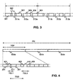
- Figure 3 illustrates an example of a compressed mode transmission according to the first preferred embodiment of the invention, where a certain transmission period is repeated. The repeated period is marked with arrows in Figure 3. The transmission period comprises three transmission gaps 311, 312 and 313. The transmission gap 311 is longer than the transmission gaps 312 and 313, which in Figure 3 have the same duration by the way of example. The
frames 301 are similar frames as the frames sent during continuous transmission mode. The transmission gap 311 is in the middle of a frame, covering the time slots in the middle of a frame. Data related toframe 302 is transmitted in the first time slots of a frame and in the last time slots of a frame. The transmission gap 312 covers a certain number of the first time slots of a frame, and the transmission gap 313 covers a certain number of the last time slots of a frame. Data related to frame 303 is sent in the end of a frame, and data related to frame 304 is sent in the beginning of a frame. - It is preferable to select the durations of the transmission gaps and the distances of the transmission gaps within a transmission period so that the transmission/receipt is intermitted during different time slots in each transmission gap. This way as many different synchronization symbols as possible can be captured on another frequency. If possible, the transmission gaps should cover all time slots in a frame. A preferred number of transmission gaps within a transmission period and the preferred durations of the transmission gaps depends, for example, on the method which is used to create the transmission gaps. The transmission gaps can be created, for example, by puncturing coded data, by reducing the spreading factor or by transmitting less data in the frames which overlap the transmission gaps in time.
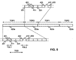
- Figure 4 illustrates an example of a transmission period according to a second preferred embodiment of the invention. In a method according to the second preferred embodiment of the invention, there are two
transmission gaps shorter transmission gap 411 is placed in the middle of theframe 401 and thelonger transmission gap 412 is overlapping twoframes - The transmission gap pattern presented in Figure 4 can be defined using, for example, the following parameters: duration of the first transmission gap (TGL1), duration of the second transmission gap (TGL2), distance between the transmission gaps (TGD), duration of the transmission gap period (TGP), duration of the transmission gap pattern (PD), the number of the frame in which the first transmission gap starts (SFN) and the number of the time slot in which the first transmission gap starts (SN). When compared to the 3G TS 25.215 specification, only a parameter defining the duration of the other transmission gap (TGL2) has to be added to the parameter list defined there. Only one additional parameter needs to be signaled between the network elements in the cellular network and from the cellular network to a mobile station. A method according to the second preferred embodiment of the invention can thus be supported with small changes in the existing system.
- When puncturing is used, about one third of the coded data bits can be ignored without a drastic deterioration of the quality of the transmission. In UTRA FDD system, where there are 15 time slots per frame, the maximum feasible length of a transmission gap is thus 5 time slots. In a method according to the second preferred embodiment, the duration of the shorter transmission gap, which is within a frame, is thus preferably 5 time slots in UTRA FDD system. The maximum feasible length for the longer time slot, which overlaps two sequential frames, is 10 time slots in UTRA FDD system. The switching time from one frequency to another and back is either one or two time slots. Table 5 summarizes the maximum numbers of synchronization symbols a mobile station can capture from a neighboring cell during an interfrequency handover when a method according to the second preferred embodiment is employed.
Table 5 Number of captured synchronization symbols when a method according to the second preferred embodiment of the invention is used Transmission gap duration Switching time Number of captured synchronization symbols 5+10 time slots 1 time slot (5-1) + (10-1) = 13 2 time slots (5-2) + (10-2) =11 - The numbers of captured synchronization symbols in Table 5 can be compared to the numbers of captured synchronization symbols presented in Table 1. Using a method according to the second preferred embodiment of the invention, it is possible to capture more synchronization symbols than when the spreading factor is reduced by two and the transmission gap length is 7 time slots. When compared to one transmission gap of 14 time slots, either the same amount of synchronization symbols (switching time is one time slot) or one less (switching time is two time slots) is captured. Even in the latter alternative, 11 synchronization symbols can be captured. This is enough for performing an interfrequency handover.
- In addition, in a code limited situation, when a secondary scrambling code may need to be taken into use, a method according to the second preferred embodiment of the invention requires smaller increase in the transmission power, when puncturing is used to create the transmission gaps. The method according to the second preferred embodiment of the invention is thus very suitable for handovers in code limited situations.
- Figure 5 illustrates the beginning of a transmission gap pattern according to a third preferred embodiment of the invention. In Figure 5, two transmission gap periods 420 and 520 are repeated alternatingly. The
transmission gaps - As discussed above, it is also possible that some of the cyclically repeated transmission periods comprise only one transmission gap or that the transmission gaps in some of the transmission gap periods have equal durations.
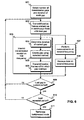
- Figure 6 presents a flowchart of a method according to the invention. This method illustrates, how in a certain communication connection data is transmitted in compressed mode. In
step 601 the transmission gap periods, the order for their cyclical repetition and, especially, the number of the transmission gaps within each transmission gap period and the duration of each gap are defined. Typically, in a handover these are defined by the network and the information is then usually signaled to a mobile station. This way the mobile station can receive properly the information transmitted in compressed mode. - In compressed mode the steps 602-610 are repeated. In
step 602 information related to the communication connection is transmitted/received in frames similarly as during continuous mode operation. This is done until the first transmission gap of the first transmission gap period is reached. Thereafter instep 603 the transmission/receipt of information of the communication connection is intermitted. Instep 604 the duration of the transmission gap is determined, and instep 605 the transmission gap is created with a selected method, for example, using puncturing or by reducing the spreading factor by two. In step 606, the frames which overlap with the transmission gap are transmitted/received. The transmission power of these frames is typically larger than the transmission power of the frames transmitted instep 602. - When the transmission gap is passed, in
step 609 it is checked, if the current transmission gap is the last in the current transmission gap period. If it is not, then frames are instep 602 again transmitted/received similarly as in continuous mode operation, until the next transmission gap within the current transmission gap period is reached. If the transmission gap is the last one within the current transmission gap period, then instep 610 it is checked if the current transmission gap period is the last in the compressed mode. If the compressed mode still continues, then again frames are transmitted/received similarly as in continuous mode, until the first transmission gap in the next transmission gap period is reached (step 602). If the transmission gap period(s) is (are) already repeated as many times as specified when entering the compressed mode operation, then the compressed mode transmission is terminated instep 611. - During the transmission gaps on the first frequency, it is possible to perform measurements on a second frequency (step 607). Further, data can be received on the second frequency (step 608). The data may be, for example, the synchronization symbols of a neighboring cell.
- Figure 7 presents examples of a
mobile station 700 and twonetwork elements mobile station 700, in thenetwork element 710 and in thenetwork control element 720. - The
mobile station 700 comprises a user interface (UI) 701, acontrol unit 702, abaseband unit 703 and a radio frequency (RF)unit 704. The RF unit is a receiver/transmitter that handles frequency separation, possible frequency conversion to/from intermediate frequencies or to baseband, and analog/digital conversion. The baseband unit is responsible of the physical (first) layer processing, such as the channel coding, interleaving and multiplexing. It may be implemented using hardware (typically ASICs), software (typically digital signal processing DSP), or both. The baseband unit may also implement part or all of thelayer 2 radio protocols.Layer 3 protocols and possible also part oflayer 2 protocols are implemented in the control unit. - For the
mobile station 700 to be able to operate during a handover where a method according to the invention is used, the compressedmode reception block 706 inbaseband unit 703 may have to be modified. The modification is related, first, to receiving compressed data on a first frequency and, secondly, to determining the synchronization symbols from data received on a second frequency. Thesignaling unit 705 in thecontrol unit 702 may also need modification. For example, the signaling unit needs to understand a signaling message where more than one duration of a transmission gap within a transmission gap periods defined. - Term mobile terminal refers here to a wireless terminal of a cellular system. It may be a portable terminal, which a person may carry, or a wireless terminal installed in some other equipment. For example, in UMTS a mobile terminal is usually called User Equipment (UE).
- The
network element 710 is the network element with which the mobile station has a communication connection over the radio interface. It is thus usually called a base station, but in UTRA it is also called a node-B. This network element has the radio frequency (RF)unit 711, abaseband unit 712, acontrol unit 713 and aninterface unit 714, via which communication with rest of the cellular network occurs. In order to support the compressed mode transmission according to the invention, thesignaling unit 716 in the control unit needs to understand signaling, where more than one duration of a transmission gap within a transmission gap period is defined. Further, the compressedmode transmission unit 715 has to be able to create the transmission gaps of various durations within a transmission gap period. - The
network control element 720 is the network element which is responsible, for example, for the control and allocation of radio resources in the cellular network. This control element decides, for example, when a certain communication connection enters compressed mode transmission and the transmission gap pattern used in said compressed mode transmission. Therefore, in order to support a method according to the invention, thecontrol unit 712 of the network control element may have to be modified to be able to make compressed mode decisions according to the invention. The modifications are presented in Figure 6 with the compressedmode decision unit 723. Further, thenetwork control element 720 typically signals information about the transmission gap pattern both to a base station and to a mobile station. Therefore thesignaling unit 724 has to implement signaling which supports methods according to the invention. - The
network control element 720 comprises also aninterface unit 722 via which it communicates with thenetwork element 710. Further, it may comprise various units related to the multiplexing of connections and routing of information in the radio access network. - The
network control element 720 may be, for example, the radio network controller (RNC) of a UTRA. It is also possible that the decision about the transmission gap period and transmission gap durations in done in the same network element which transmits the data over the radio interface. - In this description a transmission pattern during a compressed mode transmission is defined using the following parameters: the duration of each transmission gap within transmission periods, the distance between two consequent transmission gaps within a transmission period, the duration(s) of the transmission period(s), the duration of the transmission pattern, and the numbers of the frame and of the time slot where the first transmission gap of the first transmission period starts. This set of parameters is used as an example, and the method according to the invention is not restricted to methods, where the positions of transmission gaps during a compressed mode operation is defined using these parameters. The names of the parameters may be different, or the positions of transmission gaps during a compressed mode operation may be defined using other parameters. The invention applies to all methods where certain transmission gaps are periodically repeated during the compressed mode operation.
- Further, the method according to the invention is applicable to any cellular system employing CDMA technique for multiplexing communication connections. The UTRA FDD system is presented as an example of such systems.
- [1] 3G TS.25.215 Physical layer measurements
- [2] TSGR1#7(99)b27, Ericsson: "Use of multiple scrambling codes in compressed mode" TSG-
RAN Working Group 1 meeting 7, Hannover, Germany, Aug. 30 - Sep. 3, 1999.
Claims (23)
- A method (600) for preparing an interfrequency handover of a communication connection from a first frequency to a second frequency, comprising the following steps of- periodically intermitting (603) the transmission/receipt of data on the first frequency for transmission gaps, where the number of transmission gaps is at least one during each transmission gap period and where a transmission gap pattern comprising a sequence of transmission gap periods (420, 520) is used, and- performing (607) measurements on the second frequency during the transmission gaps on the first frequency,characterized in that the said step of intermitting the transmission/receipt of data comprises a substep of intermitting (604, 606) the transmission/receipt of data during at least one transmission gap period for a transmission gap (311, 411) having a first duration and for a second transmission gap (312, 412) having a second duration, which second duration is different from the first duration.
- A method according to claim 1, further comprising the step of receiving (608) system information on the second frequency during a transmission gap on the first frequency.
- A method according to claim 1 or 2, wherein in the step of intermitting the transmission/receipt of data, all the transmission gap periods (420, 520) of the transmission gap pattern are identical from the beginning of the first transmission gap within a transmission period to the end of the last transmission gap within the same transmission period.
- A method according to claim 1 or claim 2, wherein in the step of intermitting the transmission/receipt of data, in said transmission gap pattern, a certain number of transmission periods (420, 520) is repeated cyclically.
- A method according any preceding claim, further comprising the steps of- coding original data before transmission and- transmitting coded data in first frames (201, 301), during which the transmission is continuous,wherein in the step of intermitting the transmission/receipt of data comprises the substep of transmitting, coded data in second frames (302, 303, 304, 401, 402), during which the transmission/receipt of coded data is intermitted.
- A method according to claim 5, comprising the step of, before transmission, puncturing (605) the coded data transmitted in the second frames, so that the amount of transmitted coded data in the first frames and in the second frames corresponds to a certain fixed amount of original data.
- A method according to claim 5, wherein the amount of coded data transmitted in the first frames and in the second frames corresponds to a certain fixed amount of original data.
- A method according to claim 7, wherein the step of intermitting the transmission/receipt of data comprises puncturing (605) the coded data transmitted in the second frames, so that the amount of transmitted coded data in the first frames and in the second frames corresponds to said fixed amount of original data.
- A method according to any of claims 5 to 8, wherein the frames comprise a certain number of time slots, and- in the substep of intermitting the transmission/receipt of data, transmission/receipt is intermitted during said transmission gap having the first duration during certain first time slots of a frame (311, 411) and during said transmission gap having the second duration during certain second time slots of a frame (312, 313, 412), which second time slots are not the same time slots as the first time slots.
- A method according to claim 9, wherein in the substep of intermitting the transmission/receipt of data, the transmission gap (412) having a first duration occurs during two sequential frames and the transmission gap (411) having a second duration occurs within one frame.
- A method according to claim 10, wherein the second duration (411) is shorter than the first duration (412).
- A method according to claim 11, wherein the first duration (412) is substantially twice the second duration (411).
- A method according to claim 12, wherein substantially half of the transmission gap (412) having the first duration occurs during in the previous frame of said two subsequent frames.
- A method according to any preceding claim, comprising the following steps of- deciding (601) the number of transmission gaps within each transmission gap period,- deciding (601) the duration of each transmission gap period,- deciding (601) the duration of each transmission gap,- deciding (601) the durations between the transmission gaps, and- transmitting information about the duration of each transmission gap and the durations between the transmission gaps from a cellular network to a mobile station.
- A method according to any of claims 1 to 14, wherein there are two transmission gap periods (420, 520) having different durations.
- A method according to any of claim 1 to 14, wherein all transmission gap periods (420) have the same duration.
- A mobile station (700), which comprises- means (704) for receiving data on a first frequency,- means (703) for intermitting periodically the receipt of data on the first frequency during transmission gaps, where the number of transmission gaps is at least one during each transmission gap period and a transmission gap pattern comprising a sequence of transmission periods (420, 520) is used, and- means (703, 704) for performing measurements on a second frequency during the transmission gaps, characterized in that- the means for intermitting the receipt of data comprise means (706) for intermitting the receipt of data within at least one transmission gap period for a transmission gap having a first duration and for a second transmission gap having a second duration, where the first duration is different from the second duration and in that- the mobile station further comprises means (705) for receiving information about the durations of at least two transmission gaps.
- A mobile station according to claim 17, comprising- means for receiving system information on the second frequency during the transmission gaps on the first frequency, and- means for determining a scrambling code group using the received system information.
- A mobile station according to claim 17 or 18, wherein said mobile station is a UMTS mobile station.
- A network element (710), which comprises- means (711) for transmitting data on a frequency and- means (712) for intermitting periodically the transmission of data related to a communication connection during transmission gaps, where the number of transmission gaps is at least one during each transmission gap period and where a transmission gap pattern comprising a sequence of transmission periods (420, 520) is used, characterized in that- the means for intermitting the transmission of data comprise means (715) for intermitting the receipt of data within at least one transmission gap period for a transmission gap having a first duration and for a second transmission gap having a second duration, where the first duration is different from the second duration, and in that- the network element further comprises means (714, 716) for receiving information about the duration of at least two transmission gaps within one transmission gap period.
- A network element according to claim 20, wherein said network element is a base station of the UTRA network.
- A network control element (720), which comprises- means (721) for defining a transmitting gap pattern comprising a sequence of transmission gap periods, where the number of transmission gaps is at least one during each transmission period, and- means (722) for transmitting information about the transmission periods, characterized in that- the means for deciding the transmission gap periods comprise means (723) for deciding a first duration for at least a transmission gap and a second duration of a second transmission gap, where the first duration is different from the second duration and said transmission gaps are within at least one transmission period, and in that- the network control element further comprises means (724) for transmitting information about the duration of at least two transmission gaps within one transmission gap period.
- A network element according to claim 22, wherein said network element is a radio network controller of the UTRA network.
Priority Applications (1)
| Application Number | Priority Date | Filing Date | Title |
|---|---|---|---|
| DE60131066T DE60131066T3 (en) | 2000-01-10 | 2001-01-09 | METHOD FOR PREPARING AN INTERFACE TRANSMITTER, NETWORK ELEMENT AND MOBILE STATION |
Applications Claiming Priority (3)
| Application Number | Priority Date | Filing Date | Title |
|---|---|---|---|
| FI20000043A FI109862B (en) | 2000-01-10 | 2000-01-10 | Procedure for preparing a handover between frequencies, a network element and a mobile station |
| FI20000043 | 2000-01-10 | ||
| PCT/FI2001/000016 WO2001052585A1 (en) | 2000-01-10 | 2001-01-09 | Method for preparing an interfrequency handover, a network element and a mobile station |
Publications (3)
| Publication Number | Publication Date |
|---|---|
| EP1247417A1 EP1247417A1 (en) | 2002-10-09 |
| EP1247417B1 true EP1247417B1 (en) | 2007-10-24 |
| EP1247417B2 EP1247417B2 (en) | 2011-07-27 |
Family
ID=8557012
Family Applications (1)
| Application Number | Title | Priority Date | Filing Date |
|---|---|---|---|
| EP01901229A Expired - Lifetime EP1247417B2 (en) | 2000-01-10 | 2001-01-09 | Method for preparing an interfrequency handover, a network element and a mobile station |
Country Status (14)
| Country | Link |
|---|---|
| US (1) | US7020108B2 (en) |
| EP (1) | EP1247417B2 (en) |
| JP (3) | JP2001224053A (en) |
| KR (1) | KR100661452B1 (en) |
| CN (1) | CN1223235C (en) |
| AT (1) | ATE376757T1 (en) |
| AU (1) | AU2001226839A1 (en) |
| BR (2) | BRPI0107398B1 (en) |
| CA (1) | CA2395756C (en) |
| DE (1) | DE60131066T3 (en) |
| ES (1) | ES2295127T5 (en) |
| FI (1) | FI109862B (en) |
| WO (1) | WO2001052585A1 (en) |
| ZA (1) | ZA200205455B (en) |
Families Citing this family (42)
| Publication number | Priority date | Publication date | Assignee | Title |
|---|---|---|---|---|
| FI112772B (en) * | 2000-02-18 | 2003-12-31 | Nokia Corp | Reduction of interference in inter-frequency measurement |
| FI112562B (en) * | 2000-02-29 | 2003-12-15 | Nokia Corp | Determination of measurement apertures in mutual frequency measurement |
| KR100384899B1 (en) * | 2001-01-10 | 2003-05-23 | 한국전자통신연구원 | Method for seamless inter frequency hard handover in wireless telecommunication system |
| KR100592597B1 (en) * | 2001-01-10 | 2006-06-26 | 한국전자통신연구원 | A Method for Handover using Compressed Mode and Common Frequency between Neighbor Cells |
| FI111110B (en) * | 2001-02-20 | 2003-05-30 | Nokia Corp | Method and arrangement for increasing the versatility of the compressed state for measurements between systems |
| JP3462476B2 (en) | 2001-03-28 | 2003-11-05 | 株式会社東芝 | Wireless communication system and base station |
| JP3918477B2 (en) * | 2001-09-03 | 2007-05-23 | 日本電気株式会社 | Handover system |
| JP2003143639A (en) * | 2001-11-07 | 2003-05-16 | Nec Corp | Mobile communication system, base station, mobile device and inter-frequency hho method used for them |
| EP1320271B1 (en) * | 2001-12-04 | 2004-02-25 | Alcatel | Basestation for UMTS for transmission of time slot types |
| FR2838019B1 (en) * | 2002-03-29 | 2004-08-27 | Evolium Sas | COMPRESSED MODE CONFIGURATION METHOD IN A MOBILE RADIO COMMUNICATION SYSTEM |
| JP3999567B2 (en) * | 2002-05-23 | 2007-10-31 | 株式会社エヌ・ティ・ティ・ドコモ | Wireless communication system, wireless terminal, wireless base station, control device, and communication method |
| FI114275B (en) * | 2002-05-31 | 2004-09-15 | Nokia Corp | Control of handover between frequencies |
| JP2004088522A (en) * | 2002-08-28 | 2004-03-18 | Nec Corp | Mobile communication system, inter-frequency ho method therefor, mobile station, base station, base station control apparatus and program |
| JP2004153316A (en) * | 2002-10-28 | 2004-05-27 | Ntt Docomo Inc | Method for handover controlling, mobile communication system and controller |
| JP4197266B2 (en) * | 2003-04-10 | 2008-12-17 | 株式会社エヌ・ティ・ティ・ドコモ | Radio control apparatus and handover control method |
| SE0303031D0 (en) * | 2003-11-12 | 2003-11-12 | Ericsson Telefon Ab L M | Inter-Frequency and inter-rat handover measurements |
| CN101095365B (en) * | 2003-12-23 | 2011-01-26 | 艾利森电话股份有限公司 | Controlling reconfiguration in a celluar communication system |
| WO2005064971A1 (en) * | 2003-12-29 | 2005-07-14 | Telefonaktiebolaget Lm Ericsson (Publ) | Method, terminal unit and base station unit for providing data communication in a code division multiple access (cdma) telecommunications system |
| WO2005064972A1 (en) * | 2003-12-29 | 2005-07-14 | Telefonaktiebolaget Lm Ericsson (Publ) | Method, terminal unit and base station unit for providing data communication in a code division multiple access (cdma) telecommunications system |
| JP5049463B2 (en) * | 2004-12-14 | 2012-10-17 | 富士通株式会社 | Wireless communication system, base station, mobile station, and wireless communication method |
| GB0506539D0 (en) * | 2005-03-31 | 2005-05-04 | Koninkl Philips Electronics Nv | Method and apparatus for transmitting data, and a communication system |
| US8068835B2 (en) | 2005-10-27 | 2011-11-29 | Qualcomm Incorporated | Tune-away and cross paging systems and methods |
| US9247467B2 (en) * | 2005-10-27 | 2016-01-26 | Qualcomm Incorporated | Resource allocation during tune-away |
| US8134977B2 (en) * | 2005-10-27 | 2012-03-13 | Qualcomm Incorporated | Tune-away protocols for wireless systems |
| US8229433B2 (en) * | 2005-10-27 | 2012-07-24 | Qualcomm Incorporated | Inter-frequency handoff |
| WO2007132861A1 (en) * | 2006-05-16 | 2007-11-22 | Sharp Kabushiki Kaisha | Mobile communication system, mobile station apparatus, base station apparatus and mobile communication method |
| US9036607B2 (en) | 2006-05-23 | 2015-05-19 | Sharp Kabushiki Kaisha | Method, mobile station device, base station device, and mobile communication system for gap-generation determination |
| EP1860814A1 (en) * | 2006-05-26 | 2007-11-28 | Nokia Siemens Networks Gmbh & Co. Kg | Method for interference reduction |
| US8014343B2 (en) | 2006-09-20 | 2011-09-06 | Interdigital Technology Corporation | Method for enhanced dedicated channel (E-DCH) transmission overlap detection for compressed mode gap slots |
| EP1909523A1 (en) * | 2006-10-02 | 2008-04-09 | Matsushita Electric Industrial Co., Ltd. | Improved acquisition of system information of another cell |
| US20080085710A1 (en) * | 2006-10-05 | 2008-04-10 | Samsung Electronics Co., Ltd. | Gap scheduling method based on minimum gap patterns in long term evolution system |
| US20080176546A1 (en) * | 2007-01-23 | 2008-07-24 | Qualcomm Incorporated | Application programming interface (api) for a receiver in a wireless communications device |
| CN101682853A (en) * | 2007-05-31 | 2010-03-24 | 松下电器产业株式会社 | Gap support measuring method |
| GB0712702D0 (en) * | 2007-06-29 | 2007-08-08 | Nokia Corp | A method for providing measurement gaps |
| US20090191883A1 (en) * | 2008-01-25 | 2009-07-30 | Infineon Technologies Ag | Method and device for transmitting data |
| WO2009116907A1 (en) * | 2008-03-20 | 2009-09-24 | Telefonaktiebolaget L M Ericsson (Publ) | Methods for provision of system information, computer programs, network node, terminal, and radio access network |
| EP2271010A1 (en) * | 2008-04-22 | 2011-01-05 | Osaka University | Wireless communication system, transmitter apparatus, receiver apparatus, and communication method |
| US20100034141A1 (en) * | 2008-08-06 | 2010-02-11 | Qualcomm Incorporated | Method and apparatus for initiating random access procedure in wireless networks |
| US9204347B2 (en) * | 2009-06-23 | 2015-12-01 | Google Technology Holdings LLC | HARQ adaptation for acquisition of neighbor cell system information |
| CN103404199B (en) * | 2010-10-29 | 2017-05-24 | 华为技术有限公司 | Design and method to enable single radio handover |
| CN103220702B (en) * | 2012-01-19 | 2016-11-02 | 华为技术有限公司 | A kind of alien-frequency district measuring method, device and system |
| US20130223428A1 (en) * | 2012-02-28 | 2013-08-29 | Qualcomm Incorporated | Method and apparatus for irat measurement when in td-scdma connected mode |
Family Cites Families (17)
| Publication number | Priority date | Publication date | Assignee | Title |
|---|---|---|---|---|
| JP3296822B2 (en) | 1993-06-14 | 2002-07-02 | テレフオンアクチーボラゲツト エル エム エリクソン | Time alignment of transmission in downlink of CDMA system |
| TW306102B (en) * | 1993-06-14 | 1997-05-21 | Ericsson Telefon Ab L M | |
| US5883899A (en) * | 1995-05-01 | 1999-03-16 | Telefonaktiebolaget Lm Ericsson | Code-rate increased compressed mode DS-CDMA systems and methods |
| US5896368A (en) * | 1995-05-01 | 1999-04-20 | Telefonaktiebolaget Lm Ericsson | Multi-code compressed mode DS-CDMA systems and methods |
| FI105252B (en) * | 1997-07-14 | 2000-06-30 | Nokia Mobile Phones Ltd | A method for allocating time to a mobile station |
| KR100252932B1 (en) * | 1997-11-06 | 2000-04-15 | 서평원 | Method and System for Providing a Inter-frequency Handoff in a CDMA Cellular Telephone System |
| EP1612960B8 (en) | 1998-03-26 | 2010-05-19 | Mitsubishi Denki Kabushiki Kaisha | Spread spectrum communication method |
| DE69938979D1 (en) | 1998-04-23 | 2008-08-07 | Mitsubishi Electric Corp | System and transmitter used in a mobile radio communication system for monitoring frequencies in another system |
| GB2338377A (en) * | 1998-06-12 | 1999-12-15 | Fujitsu Ltd | Hand-off in cellular mobile communications networks |
| FI108270B (en) * | 1998-11-09 | 2001-12-14 | Nokia Corp | Method and arrangement for optimized timing of measurements in co-operation with interval frame procedure in a cellular radio system |
| US6507582B1 (en) * | 1999-05-27 | 2003-01-14 | Qualcomm Incorporated | Radio link protocol enhancements for dynamic capacity wireless data channels |
| KR100680070B1 (en) * | 1999-06-29 | 2007-02-09 | 유티스타콤코리아 유한회사 | Method for transmitting data inter-frequency/inter-system in mobile communication system |
| EP1081979A1 (en) * | 1999-08-31 | 2001-03-07 | TELEFONAKTIEBOLAGET L M ERICSSON (publ) | Subscriber station, network control means and method for carrying out inter-frequency measurements in a mobile communication system |
| EP1081978A1 (en) * | 1999-08-31 | 2001-03-07 | TELEFONAKTIEBOLAGET L M ERICSSON (publ) | Subscriber station and method for carrying out inter-frequency measurement in a mobile communication system |
| US6868075B1 (en) * | 1999-09-28 | 2005-03-15 | Telefonaktiebolaget Lm Ericsson (Publ) | Method and apparatus for compressed mode communications over a radio interface |
| US6597679B1 (en) * | 1999-12-01 | 2003-07-22 | Telefonaktiebolat Lm Ericsson | Control of compressed mode transmission in WCDMA |
| US6501744B1 (en) * | 1999-12-22 | 2002-12-31 | Koninklijke Philips Electronics N.V. | Slotted mode in wireless CDMA systems |
-
2000
- 2000-01-10 FI FI20000043A patent/FI109862B/en not_active IP Right Cessation
-
2001
- 2001-01-09 BR BRPI0107398A patent/BRPI0107398B1/en unknown
- 2001-01-09 DE DE60131066T patent/DE60131066T3/en not_active Expired - Lifetime
- 2001-01-09 CN CNB018035957A patent/CN1223235C/en not_active Expired - Lifetime
- 2001-01-09 AT AT01901229T patent/ATE376757T1/en active
- 2001-01-09 KR KR1020027008843A patent/KR100661452B1/en active IP Right Grant
- 2001-01-09 AU AU2001226839A patent/AU2001226839A1/en not_active Abandoned
- 2001-01-09 EP EP01901229A patent/EP1247417B2/en not_active Expired - Lifetime
- 2001-01-09 WO PCT/FI2001/000016 patent/WO2001052585A1/en active IP Right Grant
- 2001-01-09 ES ES01901229T patent/ES2295127T5/en not_active Expired - Lifetime
- 2001-01-09 BR BR0107398-2A patent/BR0107398A/en active IP Right Grant
- 2001-01-09 CA CA002395756A patent/CA2395756C/en not_active Expired - Lifetime
- 2001-01-10 US US09/757,917 patent/US7020108B2/en not_active Expired - Lifetime
- 2001-01-10 JP JP2001002770A patent/JP2001224053A/en not_active Withdrawn
-
2002
- 2002-07-09 ZA ZA200205455A patent/ZA200205455B/en unknown
-
2005
- 2005-10-20 JP JP2005305975A patent/JP2006094550A/en not_active Withdrawn
-
2009
- 2009-07-06 JP JP2009159890A patent/JP2009268142A/en active Pending
Also Published As
| Publication number | Publication date |
|---|---|
| ATE376757T1 (en) | 2007-11-15 |
| JP2009268142A (en) | 2009-11-12 |
| US7020108B2 (en) | 2006-03-28 |
| KR100661452B1 (en) | 2006-12-27 |
| WO2001052585A1 (en) | 2001-07-19 |
| ES2295127T3 (en) | 2008-04-16 |
| ZA200205455B (en) | 2004-10-27 |
| BR0107398A (en) | 2002-10-22 |
| CN1395803A (en) | 2003-02-05 |
| JP2006094550A (en) | 2006-04-06 |
| ES2295127T5 (en) | 2011-12-12 |
| CA2395756A1 (en) | 2001-07-19 |
| DE60131066D1 (en) | 2007-12-06 |
| EP1247417A1 (en) | 2002-10-09 |
| KR20030004319A (en) | 2003-01-14 |
| EP1247417B2 (en) | 2011-07-27 |
| FI109862B (en) | 2002-10-15 |
| CA2395756C (en) | 2008-11-18 |
| US20010008521A1 (en) | 2001-07-19 |
| BRPI0107398B1 (en) | 2018-09-18 |
| DE60131066T3 (en) | 2012-02-09 |
| CN1223235C (en) | 2005-10-12 |
| JP2001224053A (en) | 2001-08-17 |
| DE60131066T2 (en) | 2008-08-07 |
| FI20000043A0 (en) | 2000-01-10 |
| FI20000043A (en) | 2001-07-11 |
| AU2001226839A1 (en) | 2001-07-24 |
Similar Documents
| Publication | Publication Date | Title |
|---|---|---|
| EP1247417B1 (en) | Method for preparing an interfrequency handover, a network element and a mobile station | |
| JP2994527B2 (en) | Wireless connection handover procedure | |
| EP1099357B1 (en) | Method and system for providing personal base station communications | |
| EP0872052B1 (en) | Method and apparatus for performing handoff in a spread-spectrum communication system | |
| US7003296B2 (en) | Method of signaling compressed mode parameters to a mobile station | |
| JP4313061B2 (en) | A method for switching cells by a system device of a wireless communication system. | |
| CA2052960C (en) | Handoff procedure that minimizes disturbances to dtmf signalling in a cellular radio system | |
| EP1041850A1 (en) | Method and apparatus for changing radio link configurations in a mobile telecommunications system with soft handover | |
| EP0472511A2 (en) | Handoff of a mobile station between half rate and full rate channels | |
| JP3392630B2 (en) | Spread spectrum communication equipment | |
| US20030153313A1 (en) | Method for controlling an intersystem link transfer | |
| EP1219129B1 (en) | Reporting communication link information | |
| WO2003081931A1 (en) | Control of frame timing on handover | |
| AU762090B2 (en) | System and method for sending intermittent messages on the A-interface | |
| CN100450267C (en) | Preparation of an intersystem connection transfer | |
| EP1351535B1 (en) | Control of frame timing on handover | |
| WO1996042174A1 (en) | Changing a service option in a cdma communication system | |
| WO1998054916A1 (en) | Method and apparatus for performing mobile station handoff in a code division multiple access communication system | |
| KR20000000723A (en) | Softer handoff method within cellular mobile telecommunication system | |
| MXPA97004857A (en) | Method of switching enabled |
Legal Events
| Date | Code | Title | Description |
|---|---|---|---|
| PUAI | Public reference made under article 153(3) epc to a published international application that has entered the european phase |
Free format text: ORIGINAL CODE: 0009012 |
|
| 17P | Request for examination filed |
Effective date: 20020725 |
|
| AK | Designated contracting states |
Kind code of ref document: A1 Designated state(s): AT BE CH CY DE DK ES FI FR GB GR IE IT LI LU MC NL PT SE TR |
|
| AX | Request for extension of the european patent |
Free format text: AL;LT;LV;MK;RO;SI |
|
| GRAP | Despatch of communication of intention to grant a patent |
Free format text: ORIGINAL CODE: EPIDOSNIGR1 |
|
| GRAS | Grant fee paid |
Free format text: ORIGINAL CODE: EPIDOSNIGR3 |
|
| GRAA | (expected) grant |
Free format text: ORIGINAL CODE: 0009210 |
|
| AK | Designated contracting states |
Kind code of ref document: B1 Designated state(s): AT BE CH CY DE DK ES FI FR GB GR IE IT LI LU MC NL PT SE TR |
|
| REG | Reference to a national code |
Ref country code: GB Ref legal event code: FG4D |
|
| REG | Reference to a national code |
Ref country code: CH Ref legal event code: EP |
|
| REG | Reference to a national code |
Ref country code: IE Ref legal event code: FG4D |
|
| REG | Reference to a national code |
Ref country code: CH Ref legal event code: NV Representative=s name: E. BLUM & CO. AG PATENT- UND MARKENANWAELTE VSP |
|
| REF | Corresponds to: |
Ref document number: 60131066 Country of ref document: DE Date of ref document: 20071206 Kind code of ref document: P |
|
| REG | Reference to a national code |
Ref country code: SE Ref legal event code: TRGR |
|
| ET | Fr: translation filed | ||
| REG | Reference to a national code |
Ref country code: ES Ref legal event code: FG2A Ref document number: 2295127 Country of ref document: ES Kind code of ref document: T3 |
|
| PG25 | Lapsed in a contracting state [announced via postgrant information from national office to epo] |
Ref country code: PT Free format text: LAPSE BECAUSE OF FAILURE TO SUBMIT A TRANSLATION OF THE DESCRIPTION OR TO PAY THE FEE WITHIN THE PRESCRIBED TIME-LIMIT Effective date: 20080324 |
|
| PG25 | Lapsed in a contracting state [announced via postgrant information from national office to epo] |
Ref country code: DK Free format text: LAPSE BECAUSE OF FAILURE TO SUBMIT A TRANSLATION OF THE DESCRIPTION OR TO PAY THE FEE WITHIN THE PRESCRIBED TIME-LIMIT Effective date: 20071024 |
|
| PLBI | Opposition filed |
Free format text: ORIGINAL CODE: 0009260 |
|
| PLAX | Notice of opposition and request to file observation + time limit sent |
Free format text: ORIGINAL CODE: EPIDOSNOBS2 |
|
| PG25 | Lapsed in a contracting state [announced via postgrant information from national office to epo] |
Ref country code: BE Free format text: LAPSE BECAUSE OF FAILURE TO SUBMIT A TRANSLATION OF THE DESCRIPTION OR TO PAY THE FEE WITHIN THE PRESCRIBED TIME-LIMIT Effective date: 20071024 Ref country code: MC Free format text: LAPSE BECAUSE OF NON-PAYMENT OF DUE FEES Effective date: 20080131 |
|
| 26 | Opposition filed |
Opponent name: QUALCOMM INCORPORATED Effective date: 20080724 |
|
| PLBP | Opposition withdrawn |
Free format text: ORIGINAL CODE: 0009264 |
|
| NLR1 | Nl: opposition has been filed with the epo |
Opponent name: QUALCOMM INCORPORATED |
|
| PLAF | Information modified related to communication of a notice of opposition and request to file observations + time limit |
Free format text: ORIGINAL CODE: EPIDOSCOBS2 |
|
| PG25 | Lapsed in a contracting state [announced via postgrant information from national office to epo] |
Ref country code: GR Free format text: LAPSE BECAUSE OF FAILURE TO SUBMIT A TRANSLATION OF THE DESCRIPTION OR TO PAY THE FEE WITHIN THE PRESCRIBED TIME-LIMIT Effective date: 20080125 Ref country code: IE Free format text: LAPSE BECAUSE OF NON-PAYMENT OF DUE FEES Effective date: 20080109 |
|
| PG25 | Lapsed in a contracting state [announced via postgrant information from national office to epo] |
Ref country code: FI Free format text: LAPSE BECAUSE OF FAILURE TO SUBMIT A TRANSLATION OF THE DESCRIPTION OR TO PAY THE FEE WITHIN THE PRESCRIBED TIME-LIMIT Effective date: 20071024 |
|
| PLBB | Reply of patent proprietor to notice(s) of opposition received |
Free format text: ORIGINAL CODE: EPIDOSNOBS3 |
|
| PG25 | Lapsed in a contracting state [announced via postgrant information from national office to epo] |
Ref country code: CY Free format text: LAPSE BECAUSE OF FAILURE TO SUBMIT A TRANSLATION OF THE DESCRIPTION OR TO PAY THE FEE WITHIN THE PRESCRIBED TIME-LIMIT Effective date: 20071024 |
|
| PG25 | Lapsed in a contracting state [announced via postgrant information from national office to epo] |
Ref country code: LU Free format text: LAPSE BECAUSE OF NON-PAYMENT OF DUE FEES Effective date: 20080109 |
|
| REG | Reference to a national code |
Ref country code: DE Ref legal event code: R079 Ref document number: 60131066 Country of ref document: DE Free format text: PREVIOUS MAIN CLASS: H04Q0007380000 Ipc: H04W0036000000 |
|
| RIC2 | Information provided on ipc code assigned after grant |
Ipc: H04W 36/00 20090101AFI20110309BHEP |
|
| REG | Reference to a national code |
Ref country code: CH Ref legal event code: PUE Owner name: NOKIA 2011 PATENT TRUST Free format text: NOKIA CORPORATION#KEILALAHDENTIE 4#02150 ESPOO (FI) -TRANSFER TO- NOKIA 2011 PATENT TRUST#919 NORTH MARKET STREET SUITE 1600#WILMINGTON, DE 19801 (US) |
|
| PUAH | Patent maintained in amended form |
Free format text: ORIGINAL CODE: 0009272 |
|
| STAA | Information on the status of an ep patent application or granted ep patent |
Free format text: STATUS: PATENT MAINTAINED AS AMENDED |
|
| REG | Reference to a national code |
Ref country code: FR Ref legal event code: TP |
|
| 27A | Patent maintained in amended form |
Effective date: 20110727 |
|
| AK | Designated contracting states |
Kind code of ref document: B2 Designated state(s): AT BE CH CY DE DK ES FI FR GB GR IE IT LI LU MC NL PT SE TR |
|
| REG | Reference to a national code |
Ref country code: DE Ref legal event code: R102 Ref document number: 60131066 Country of ref document: DE |
|
| REG | Reference to a national code |
Ref country code: CH Ref legal event code: AEN Free format text: BREVET MAINTENU DANS UNE FORME MODIFIEE |
|
| REG | Reference to a national code |
Ref country code: DE Ref legal event code: R102 Ref document number: 60131066 Country of ref document: DE Effective date: 20110727 |
|
| REG | Reference to a national code |
Ref country code: CH Ref legal event code: PFA Owner name: 2011 INTELLECTUAL PROPERTY ASSET TRUST Free format text: NOKIA 2011 PATENT TRUST#919 NORTH MARKET STREET SUITE 1600#WILMINGTON, DE 19801 (US) -TRANSFER TO- 2011 INTELLECTUAL PROPERTY ASSET TRUST#919 NORTH MARKET STREET SUITE 1600#WILMINGTON, DE 19801 (US) |
|
| REG | Reference to a national code |
Ref country code: DE Ref legal event code: R135 Ref document number: 60131066 Country of ref document: DE |
|
| REG | Reference to a national code |
Ref country code: NL Ref legal event code: T3 |
|
| REG | Reference to a national code |
Ref country code: SE Ref legal event code: RPEO |
|
| REG | Reference to a national code |
Ref country code: NL Ref legal event code: TD Effective date: 20111111 Ref country code: NL Ref legal event code: SD Effective date: 20111111 |
|
| REG | Reference to a national code |
Ref country code: ES Ref legal event code: DC2A Ref document number: 2295127 Country of ref document: ES Kind code of ref document: T5 Effective date: 20111212 |
|
| REG | Reference to a national code |
Ref country code: FR Ref legal event code: CD Owner name: 2011 INTELLECTUAL PROPERTY ASSET TRUST, US Effective date: 20111123 |
|
| REG | Reference to a national code |
Ref country code: AT Ref legal event code: PC Ref document number: 376757 Country of ref document: AT Kind code of ref document: T Owner name: SISVEL INTERNATIONAL S.A., LU Effective date: 20111213 |
|
| REG | Reference to a national code |
Ref country code: DE Ref legal event code: R082 Ref document number: 60131066 Country of ref document: DE Representative=s name: EISENFUEHR, SPEISER & PARTNER, DE |
|
| REG | Reference to a national code |
Ref country code: ES Ref legal event code: PC2A Owner name: 2011 INTELLECTUAL PROPERTY ASSET TRUST Effective date: 20120314 |
|
| REG | Reference to a national code |
Ref country code: DE Ref legal event code: R081 Ref document number: 60131066 Country of ref document: DE Owner name: SISVEL INTERNATIONAL S.A., LU Free format text: FORMER OWNER: NOKIA CORP., ESPOO, FI Effective date: 20120215 Ref country code: DE Ref legal event code: R082 Ref document number: 60131066 Country of ref document: DE Representative=s name: EISENFUEHR, SPEISER & PARTNER, DE Effective date: 20120215 Ref country code: DE Ref legal event code: R082 Ref document number: 60131066 Country of ref document: DE Representative=s name: TBK, DE Effective date: 20120215 Ref country code: DE Ref legal event code: R081 Ref document number: 60131066 Country of ref document: DE Owner name: CORE WIRELESS LICENSING S.A.R.L., LU Free format text: FORMER OWNER: NOKIA CORP., ESPOO, FI Effective date: 20120215 Ref country code: DE Ref legal event code: R082 Ref document number: 60131066 Country of ref document: DE Representative=s name: EISENFUEHR SPEISER PATENTANWAELTE RECHTSANWAEL, DE Effective date: 20120215 Ref country code: DE Ref legal event code: R081 Ref document number: 60131066 Country of ref document: DE Owner name: SISVEL INTERNATIONAL S.A., LU Free format text: FORMER OWNER: NOKIA CORP., 02610 ESPOO, FI Effective date: 20120215 |
|
| REG | Reference to a national code |
Ref country code: GB Ref legal event code: 732E Free format text: REGISTERED BETWEEN 20120322 AND 20120328 |
|
| REG | Reference to a national code |
Ref country code: DE Ref legal event code: R082 Ref document number: 60131066 Country of ref document: DE Representative=s name: TBK, DE |
|
| REG | Reference to a national code |
Ref country code: DE Ref legal event code: R082 Ref document number: 60131066 Country of ref document: DE Representative=s name: EISENFUEHR, SPEISER & PARTNER, DE Effective date: 20120511 Ref country code: DE Ref legal event code: R081 Ref document number: 60131066 Country of ref document: DE Owner name: SISVEL INTERNATIONAL S.A., LU Free format text: FORMER OWNER: 2011 INTELLECTUAL PROPERTY ASSET TRUST, WILMINGTON, US Effective date: 20120511 Ref country code: DE Ref legal event code: R082 Ref document number: 60131066 Country of ref document: DE Representative=s name: TBK, DE Effective date: 20120511 Ref country code: DE Ref legal event code: R082 Ref document number: 60131066 Country of ref document: DE Representative=s name: EISENFUEHR SPEISER PATENTANWAELTE RECHTSANWAEL, DE Effective date: 20120511 Ref country code: DE Ref legal event code: R081 Ref document number: 60131066 Country of ref document: DE Owner name: SISVEL INTERNATIONAL S.A., LU Free format text: FORMER OWNER: 2011 INTELLECTUAL PROPERTY ASSET TRUST, WILMINGTON, DEL., US Effective date: 20120511 |
|
| REG | Reference to a national code |
Ref country code: CH Ref legal event code: PUE Owner name: SISVEL INTERNATIONAL S.A. Free format text: 2011 INTELLECTUAL PROPERTY ASSET TRUST#919 NORTH MARKET STREET SUITE 1600#WILMINGTON, DE 19801 (US) -TRANSFER TO- SISVEL INTERNATIONAL S.A.#44, RUE DE LA VALLEE#2661 LUXEMBOURG (LU) |
|
| REG | Reference to a national code |
Ref country code: DE Ref legal event code: R081 Ref document number: 60131066 Country of ref document: DE Owner name: SISVEL INTERNATIONAL S.A., LU Free format text: FORMER OWNER: CORE WIRELESS LICENSING S.A.R.L., LUXEMBOURG, LU Effective date: 20120906 Ref country code: DE Ref legal event code: R081 Ref document number: 60131066 Country of ref document: DE Owner name: SISVEL INTERNATIONAL S.A., LU Free format text: FORMER OWNER: 2011 INTELLECTUAL PROPERTY ASSET TRUST, WILMINGTON, US Effective date: 20121001 Ref country code: DE Ref legal event code: R082 Ref document number: 60131066 Country of ref document: DE Representative=s name: EISENFUEHR, SPEISER & PARTNER, DE Effective date: 20120906 Ref country code: DE Ref legal event code: R082 Ref document number: 60131066 Country of ref document: DE Representative=s name: EISENFUEHR, SPEISER & PARTNER, DE Effective date: 20121001 Ref country code: DE Ref legal event code: R082 Ref document number: 60131066 Country of ref document: DE Representative=s name: TBK, DE Effective date: 20120906 Ref country code: DE Ref legal event code: R082 Ref document number: 60131066 Country of ref document: DE Representative=s name: TBK, DE Effective date: 20121001 Ref country code: DE Ref legal event code: R082 Ref document number: 60131066 Country of ref document: DE Representative=s name: EISENFUEHR SPEISER PATENTANWAELTE RECHTSANWAEL, DE Effective date: 20121001 Ref country code: DE Ref legal event code: R082 Ref document number: 60131066 Country of ref document: DE Representative=s name: EISENFUEHR SPEISER PATENTANWAELTE RECHTSANWAEL, DE Effective date: 20120906 Ref country code: DE Ref legal event code: R081 Ref document number: 60131066 Country of ref document: DE Owner name: SISVEL INTERNATIONAL S.A., LU Free format text: FORMER OWNER: 2011 INTELLECTUAL PROPERTY ASSET TRUST, WILMINGTON, DEL., US Effective date: 20121001 |
|
| REG | Reference to a national code |
Ref country code: ES Ref legal event code: PC2A Owner name: SISVEL INTERNATIONAL S.A. Effective date: 20121204 |
|
| REG | Reference to a national code |
Ref country code: NL Ref legal event code: SD Effective date: 20121219 |
|
| REG | Reference to a national code |
Ref country code: FR Ref legal event code: TP Owner name: SISVEL INTERNATIONAL S.A., LU Effective date: 20121213 |
|
| REG | Reference to a national code |
Ref country code: GB Ref legal event code: 732E Free format text: REGISTERED BETWEEN 20130110 AND 20130116 |
|
| REG | Reference to a national code |
Ref country code: AT Ref legal event code: PC Ref document number: 376757 Country of ref document: AT Kind code of ref document: T Owner name: SISVEL INTERNATIONAL S.A., LU Effective date: 20130201 |
|
| PG25 | Lapsed in a contracting state [announced via postgrant information from national office to epo] |
Ref country code: DE Free format text: LAPSE BECAUSE OF FAILURE TO SUBMIT A TRANSLATION OF THE DESCRIPTION OR TO PAY THE FEE WITHIN THE PRESCRIBED TIME-LIMIT Effective date: 20111028 |
|
| REG | Reference to a national code |
Ref country code: DE Ref legal event code: R082 Ref document number: 60131066 Country of ref document: DE Representative=s name: EISENFUEHR SPEISER PATENTANWAELTE RECHTSANWAEL, DE Ref country code: DE Ref legal event code: R082 Ref document number: 60131066 Country of ref document: DE Representative=s name: EISENFUEHR, SPEISER & PARTNER, DE |
|
| REG | Reference to a national code |
Ref country code: DE Ref legal event code: R119 Ref document number: 60131066 Country of ref document: DE Ref country code: DE Ref legal event code: R409 Ref document number: 60131066 Country of ref document: DE |
|
| REG | Reference to a national code |
Ref country code: DE Ref legal event code: R073 Ref document number: 60131066 Country of ref document: DE |
|
| REG | Reference to a national code |
Ref country code: DE Ref legal event code: R074 Ref document number: 60131066 Country of ref document: DE |
|
| REG | Reference to a national code |
Ref country code: FR Ref legal event code: PLFP Year of fee payment: 16 |
|
| PG25 | Lapsed in a contracting state [announced via postgrant information from national office to epo] |
Ref country code: DE Free format text: LAPSE BECAUSE OF FAILURE TO SUBMIT A TRANSLATION OF THE DESCRIPTION OR TO PAY THE FEE WITHIN THE PRESCRIBED TIME-LIMIT Effective date: 20130801 |
|
| REG | Reference to a national code |
Ref country code: DE Ref legal event code: R409 Ref document number: 60131066 Country of ref document: DE |
|
| PGRI | Patent reinstated in contracting state [announced from national office to epo] |
Ref country code: DE Effective date: 20160216 |
|
| REG | Reference to a national code |
Ref country code: FR Ref legal event code: PLFP Year of fee payment: 17 |
|
| REG | Reference to a national code |
Ref country code: FR Ref legal event code: PLFP Year of fee payment: 18 |
|
| PGFP | Annual fee paid to national office [announced via postgrant information from national office to epo] |
Ref country code: DE Payment date: 20200203 Year of fee payment: 20 Ref country code: IT Payment date: 20200131 Year of fee payment: 20 Ref country code: GB Payment date: 20200128 Year of fee payment: 20 Ref country code: NL Payment date: 20200128 Year of fee payment: 20 Ref country code: ES Payment date: 20200210 Year of fee payment: 20 Ref country code: SE Payment date: 20200121 Year of fee payment: 20 Ref country code: AT Payment date: 20200121 Year of fee payment: 20 |
|
| PGFP | Annual fee paid to national office [announced via postgrant information from national office to epo] |
Ref country code: CH Payment date: 20200122 Year of fee payment: 20 |
|
| PGFP | Annual fee paid to national office [announced via postgrant information from national office to epo] |
Ref country code: FR Payment date: 20200128 Year of fee payment: 20 Ref country code: TR Payment date: 20200108 Year of fee payment: 20 |
|
| REG | Reference to a national code |
Ref country code: DE Ref legal event code: R071 Ref document number: 60131066 Country of ref document: DE |
|
| REG | Reference to a national code |
Ref country code: NL Ref legal event code: MK Effective date: 20210108 |
|
| REG | Reference to a national code |
Ref country code: CH Ref legal event code: PL |
|
| REG | Reference to a national code |
Ref country code: GB Ref legal event code: PE20 Expiry date: 20210108 |
|
| REG | Reference to a national code |
Ref country code: AT Ref legal event code: MK07 Ref document number: 376757 Country of ref document: AT Kind code of ref document: T Effective date: 20210109 |
|
| REG | Reference to a national code |
Ref country code: SE Ref legal event code: EUG |
|
| PG25 | Lapsed in a contracting state [announced via postgrant information from national office to epo] |
Ref country code: GB Free format text: LAPSE BECAUSE OF EXPIRATION OF PROTECTION Effective date: 20210108 |
|
| REG | Reference to a national code |
Ref country code: ES Ref legal event code: FD2A Effective date: 20210625 |
|
| PG25 | Lapsed in a contracting state [announced via postgrant information from national office to epo] |
Ref country code: ES Free format text: LAPSE BECAUSE OF EXPIRATION OF PROTECTION Effective date: 20210110 |