EP1247355B1 - System and method for detecting imperfect connections in optical systems - Google Patents
System and method for detecting imperfect connections in optical systems Download PDFInfo
- Publication number
- EP1247355B1 EP1247355B1 EP01903066A EP01903066A EP1247355B1 EP 1247355 B1 EP1247355 B1 EP 1247355B1 EP 01903066 A EP01903066 A EP 01903066A EP 01903066 A EP01903066 A EP 01903066A EP 1247355 B1 EP1247355 B1 EP 1247355B1
- Authority
- EP
- European Patent Office
- Prior art keywords
- light signal
- laser
- reflected light
- power
- connector
- Prior art date
- Legal status (The legal status is an assumption and is not a legal conclusion. Google has not performed a legal analysis and makes no representation as to the accuracy of the status listed.)
- Expired - Lifetime
Links
- 238000000034 method Methods 0.000 title claims description 15
- 230000003287 optical effect Effects 0.000 title description 22
- 238000012544 monitoring process Methods 0.000 claims abstract description 29
- 238000012423 maintenance Methods 0.000 claims description 5
- 239000000835 fiber Substances 0.000 description 51
- 239000013307 optical fiber Substances 0.000 description 8
- 238000010586 diagram Methods 0.000 description 7
- 238000004891 communication Methods 0.000 description 4
- 238000011109 contamination Methods 0.000 description 4
- 238000012545 processing Methods 0.000 description 4
- 229910052691 Erbium Inorganic materials 0.000 description 2
- 238000001514 detection method Methods 0.000 description 2
- 239000002019 doping agent Substances 0.000 description 2
- 230000013011 mating Effects 0.000 description 2
- 239000011149 active material Substances 0.000 description 1
- 230000003321 amplification Effects 0.000 description 1
- 230000005540 biological transmission Effects 0.000 description 1
- 229910003460 diamond Inorganic materials 0.000 description 1
- 239000010432 diamond Substances 0.000 description 1
- 239000000428 dust Substances 0.000 description 1
- 230000000694 effects Effects 0.000 description 1
- UYAHIZSMUZPPFV-UHFFFAOYSA-N erbium Chemical compound [Er] UYAHIZSMUZPPFV-UHFFFAOYSA-N 0.000 description 1
- 238000010348 incorporation Methods 0.000 description 1
- 238000003199 nucleic acid amplification method Methods 0.000 description 1
- 239000003921 oil Substances 0.000 description 1
- 229910052761 rare earth metal Inorganic materials 0.000 description 1
- 239000004065 semiconductor Substances 0.000 description 1
- 230000008054 signal transmission Effects 0.000 description 1
- 238000012546 transfer Methods 0.000 description 1
Images




Classifications
-
- H—ELECTRICITY
- H04—ELECTRIC COMMUNICATION TECHNIQUE
- H04B—TRANSMISSION
- H04B10/00—Transmission systems employing electromagnetic waves other than radio-waves, e.g. infrared, visible or ultraviolet light, or employing corpuscular radiation, e.g. quantum communication
- H04B10/07—Arrangements for monitoring or testing transmission systems; Arrangements for fault measurement of transmission systems
- H04B10/071—Arrangements for monitoring or testing transmission systems; Arrangements for fault measurement of transmission systems using a reflected signal, e.g. using optical time domain reflectometers [OTDR]
Definitions
- the present invention relates generally to optical fiber systems and, more particularly, to systems and methods that detect an imperfect connection of fibers of an optical pump.
- optical communication systems have replaced other communication mediums due to their many advantages.
- optical communication systems typically have wide bandwidth and low attenuation, are immune to electrical noise, offer relatively secure transmission of signals, and can transmit signals over long distances.
- the most widely used amplifier includes an optical fiber doped with an optically active material, such as erbium or other rare earth elements.
- the core region of the optical fiber contains the dopant, which is optically excited to provide optical gain to an optical signal having a suitable wavelength.
- the dopant may be excited by subjecting it to an optical pump signal of a suitable pump wavelength.
- an erbium-doped fiber amplifier amplifies optical signals of wavelengths in the range of 1520 nm to 1580 nm when pumped by an optical pump signal of wavelength 980 nm or 1480 nm.
- optical pump lasers to generate the pump signal.
- the lasers generate optical pump signals of high power density in the pump fibers and the connectors.
- Imperfect connections caused, for example, by imperfect mating of fibers or by surface contamination on the fiber ends, such as oils, dust, or dirt, can absorb some of the optical pump power and cause a hot spot, which could irreparably damage the connector. Once damaged, the connector must be replaced.
- JP 05 327 622 discloses an optical transmitter having a reflection light detection function which monitors whether the optical output connector is connected or separated.
- JP 08 307 350 discloses an optical transmission system which uses Fresnel reflection to detect the disconnection of an optical connector.
- a system as claimed in claim 1 The system is characterised over D1 by the characterising portion of claim 1.
- the system prevents damage to at least one component of a laser apparatus including a laser that emits a light signal of increasing power during power up.
- At least one connector is also provided that receives the light signal from the laser, and reflects at least a portion of the light signal when an imperfect connection exists.
- the system includes a detector and a monitoring circuit.
- the detector detects the reflected light signal from the connector, and the monitoring circuit receives the reflected light signal, determines an amount of power in the reflected light signal, calculates a ratio of the power of the light signal emitted by the laser to the power in the reflected light signal, compares the ratio to a predetermined threshold to determine whether the imperfect connection exists, and shuts down the laser when the imperfect connection exists.
- a system detects an imperfect connection in a laser component.
- the system includes a laser, a connector, and a monitoring circuit.
- the laser emits a light signal;
- the connector transmits the light signal external to the laser component and reflects at least a portion of the light signal when an imperfect connection exists; and
- the monitoring circuit detects an amount of the reflected light signal and determines that the imperfect connection exists when the detected amount of the reflected light signal exceeds a predetermined amount.
- an optical amplifier in another arrangement disclosed herein, includes an active optical fiber and at least one laser component.
- the laser component provides power to the active optical fiber.
- the laser component includes a laser, a connector, and a monitoring circuit.
- the laser outputs a light signal.
- the connector transmits the light signal to the active optical fiber and reflects at least a portion of the light signal when an imperfect connection exists.
- the monitoring circuit determines whether the imperfect connection exists using the reflected light signal.
- Systems and methods in accordance with the preferred embodiment detect imperfect connection of fibers coupled to pump lasers to prevent damage to laser components due to the imperfect connection.
- the systems and methods monitor back reflection from the pump connector, as the pump laser gradually powers up, to determine whether an imperfect connection exists before the pump laser reaches an output power level that can damage the laser components.
- Fig. 1 is an exemplary system 100 in which systems and methods consistent with the preferred embodiment may be implemented.
- the system 100 includes two amplifiers 110 and 120 and a pump 130.
- Each of the amplifiers 110 and 120 may include an active amplifier, such as an Erbium-doped fiber amplifier that amplifies signals travelling along the fiber with a wavelength of approximately 1550 nm.
- the amplifier 110 amplifies signals travelling in one direction and the amplifier 120 amplifies signals travelling in the opposite direction.
- the pump 130 supplies power to the amplifiers 110 and 120.
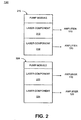
- Fig. 2 is a detailed diagram of the pump 130 in an implementation consistent with the preferred embodiment.
- the pump 130 includes two pump modules 210 and 220.
- Each of the pump modules 210 and 220 typically includes two laser components 212 and 214 and 222 and 224, respectively, for redundancy.
- the pump 130 may include a different number of pump modules and the pump modules may include a different number of laser components.
- Fig. 3 is a detailed diagram of a laser component 300, such as laser components 212, 214, 222, and 224, in an implementation consistent with the preferred embodiment.
- the laser 310 typically includes a conventional semiconductor laser emitting light in a continuous wave (CW) mode at a wavelength of 980 or 1480 nm.
- the power associated with light output from the laser 310 is typically sufficient to excite the erbium ion in the optical amplifier 110 (Fig. 1), and is often in a ragne of 100-500 mW.
- the laser 310 emits light of a different power and/or of a different wavelength.
- the power fiber 320 (320A and 320B) includes an optical fiber that connects the laser 310 to the connector 330.
- the connector 330 may include a conventional connector, such as an E2000 style connector manufactured by Diamond.
- Figs. 4A and 4B are exemplary diagrams of types of connections that may be provided by the connector 330.
- Fig. 4A illustrates a straight connection in which the fiber ends 410 and 420 have a straight cut.
- Fig. 4B illustrates an angled connection in which the fiber ends 430 and 440 have an angled cut, such as a seven degree cut. In general, straight-cut connections cause more reflection of incident light than angled-cut connections.
- the back reflection fiber 340 includes an optical fiber with one end connected to the coupler 350 and the other end connected to the detector 360 and the monitoring circuit 370.
- the coupler 350 may include a conventional directional coupler that splits a signal received on the power fiber 320A to both the power fiber 320B and a terminated fiber 342, and splits a reflected signal received on the power fiber 320B to both the power fiber 320A and the reflection fiber 340. The amount of split may vary.
- the split amount is a 99 percent to 1 percent split (i.e., the coupler 350 has a 1 percent tap). In this case, the coupler 350 transmits 99 percent of the signal received from the pump fiber 320A to the pump fiber 320B and the remaining 1 percent of the signal to the terminated fiber 342, and transmits 99 percent of the reflected signal received from the pump fiber 320B to the pump fiber 320A and the remaining 1 percent of the signal to the reflection fiber 340. In another implementation consistent with the preferred embodiment, the split amount is a 100 percent to 0 percent split.
- the coupler 350 transmits 100 percent of the signal received from the pump fiber 320A to the pump fiber 320B, and transmits 100 percent of the reflected signal received from the pump fiber 320B to the reflection fiber 340.
- the coupler 350 transmits 100 percent of the signal received from the pump fiber 320A to the pump fiber 320B, and transmits 100 percent of the reflected signal received from the pump fiber 320B to the reflection fiber 340.
- split amounts may also be possible.
- the coupler 350 When the laser 310 emits a signal, 100 percent of the signal enters the coupler 350 via pump fiber 320A. At this time, no signal enters the coupler 350 via the reflection fiber 340. If the coupler has a 1 percent tap, then the coupler 350 outputs 99 percent of the signal on pump fiber 320B and 1 percent of the signal on terminated fiber 342. Upon reflection at the connector 330 due to surface contamination, for example, 100 percent of the reflected signal enters the coupler 350 on the pump fiber 320B. No signal enters the coupler 350 via the terminated fiber 342 due to a conventional termination at the end thereof. The coupler 350 outputs 99 percent of the reflected signal back to the laser 310 on the pump fiber 320A and 1 percent of the reflected signal to the detector 360 on reflection fiber 340.
- the detector 360 may include a photodiode that generates an electrical signal in response to the back-reflected signal on the reflection fiber 340.
- the electrical signal is then fed to monitoring circuit 370, which may include a conventional transimpedance amplifier.
- the electrical signal may be in the form of a current, which causes the transimpedance amplifier to output a voltage signal that shuts down the laser 310 when the detected amount of back reflectance is more than a predetermined amount.
- the monitoring circuit 370 includes a computer, microprocessor, or similar circuitry.
- the monitoning circuit 370 shuts down the laser 310 and flags the laser component for maintenance, using, for example, a notification signal, when the amount of back reflectance is more than the predetermined amount.
- the monitoring circuit 370 may use a threshold to determine whether an imperfect connection exists at the connector.
- a clean connection will have minimal back reflection - an amount typically specified by the connector manufacturer.
- An imperfect connection due, for example, to the presence of surface contamination causes some back reflection beyond the "clean" value.
- a linear relationship often exists between the amount of power output by the laser 310 and the amount of back-reflected power from an imperfect ("unclean") connection.
- the monitoring circuit 370 calculates a ratio of the amount of power output by the laser 310 to the amount of back-reflected power. If the ratio exceeds a predetermined threshold, then the monitoring circuit 370 shuts down the laser 310 and flags the laser component for maintenance. The monitoring circuit 370 detects the presence of the imperfect connection as the laser 310 gradually powers up, allowing the monitoring circuit 370 to detect the imperfect connection before the amount of power output by the laser 310 reaches an amount that can damage the connector.
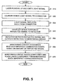
- Fig. 5 is a flowchart of exemplary processing for detecting an imperfect connection in a manner consistent with the preferred embodiment. Processing begins when the laser 310 (Fig. 3) begins to power up [step 510]. At this time, the laser 310 emits a light signal of low power. Over time, the laser 310 ramps up to emit a light signal of high power, such as 100-500 mW.
- the laser 310 As the laser 310 ramps up, it transmits the light signal to the coupler 350 via the pump fiber 320A. Assume that the coupler 350 has a 1 percent tap. The coupler 350 transmits 99 percent of the received signal to the connector 330 over pump fiber 320B and the remaining 1 percent of the signal on the terminated fiber 342 [step 520]. If the connection provided by the connector 330 is imperfect through, for example, an imperfect mating of fibers or surface contamination on the fiber ends, a portion of the signal transmitted on the pump fiber 320B reflects back from the connector 330 [step 530]. The amount of signal reflection depends on the degree of imperfection in the connection.
- the pump fiber 320B transmits the reflected signal to the coupler 350. Because the coupler 350 has a 1 percent tap, it transmits 99 percent of the reflected signal back to the laser 310 via the pump fiber 320A. The reflected signal has no effect on the laser 310. The coupler 350 transmits the remaining 1 percent of the reflected signal to the detector 360 via the reflection fiber 340 [step 540]. The detector 360 detects the reflected signal and outputs a signal indicative of the detection to the monitoring circuit 370 [step 550].
- the monitoring circuit 370 determines whether an imperfect connection exists [step 560]. To make this determination, the monitoring circuit 370 tracks the power output of the laser 310 as it ramps up. The monitoring circuit 370 determines the ratio of the amount of power output from laser 310 to the amount of power in the reflected signal. If the ratio exceeds a predetermined threshold, the monitoring circuit 370 shuts down the laser 310 and may flag the laser component for maintenance [step 570]. In one implementation consistent with the present preferred embodiment, the monitoring circuit 370 uses a table or equation relating laser 310 output power to threshold amount for its comparison.
- a three-port circulator 600 can be used in place of coupler 350.
- light output from laser 310 is supplied to a first port of circulator 600 by fiber 320A, and circulated to a second output port coupled to fiber 320B for output to connector 330. Any light reflected from connector 320 reenters the second port, and is circulated to a third output port of circulator 600 to fiber 340 for output to photodetector 360.
- Systems and methods consistent with the preferred embodiment detect imperfect connections in laser components, as the laser powers up, to prevent damage caused by the imperfect connections to the laser components.
Landscapes
- Physics & Mathematics (AREA)
- Electromagnetism (AREA)
- Engineering & Computer Science (AREA)
- Computer Networks & Wireless Communication (AREA)
- Signal Processing (AREA)
- Lasers (AREA)
- Optical Communication System (AREA)
- Laser Beam Processing (AREA)
Abstract
Description
- This application claims priority of U.S. Non-Provisional Application Serial No. 09/481,826 filed January 12, 2000.
- The present invention relates generally to optical fiber systems and, more particularly, to systems and methods that detect an imperfect connection of fibers of an optical pump.
- Optical communication systems have replaced other communication mediums due to their many advantages. For example, optical communication systems typically have wide bandwidth and low attenuation, are immune to electrical noise, offer relatively secure transmission of signals, and can transmit signals over long distances.
- Despite the low attenuation of optical communication systems, the optical signals they transmit nevertheless require amplification. Although many types of optical amplifiers currently exist, the most widely used amplifier includes an optical fiber doped with an optically active material, such as erbium or other rare earth elements. Generally, the core region of the optical fiber contains the dopant, which is optically excited to provide optical gain to an optical signal having a suitable wavelength. The dopant may be excited by subjecting it to an optical pump signal of a suitable pump wavelength. For example, an erbium-doped fiber amplifier amplifies optical signals of wavelengths in the range of 1520 nm to 1580 nm when pumped by an optical pump signal of wavelength 980 nm or 1480 nm.
- Conventional systems typically use optical pump lasers to generate the pump signal. The lasers generate optical pump signals of high power density in the pump fibers and the connectors. Imperfect connections, caused, for example, by imperfect mating of fibers or by surface contamination on the fiber ends, such as oils, dust, or dirt, can absorb some of the optical pump power and cause a hot spot, which could irreparably damage the connector. Once damaged, the connector must be replaced.
- JP 05 327 622 (D1) discloses an optical transmitter having a reflection light detection function which monitors whether the optical output connector is connected or separated. JP 08 307 350 (D2) discloses an optical transmission system which uses Fresnel reflection to detect the disconnection of an optical connector.
- Accordingly, there exists a need for a system which detects an imperfect connection before damage occurs to the connector.
- Systems and methods consistent with the present invention address this need by monitoring back reflection from the pump connector to detect an imperfect connection before damage can occur.
- In accordance with the present invention as embodied and broadly described herein, there is provided a system as claimed in claim 1. The system is characterised over D1 by the characterising portion of claim 1. The system prevents damage to at least one component of a laser apparatus including a laser that emits a light signal of increasing power during power up. At least one connector is also provided that receives the light signal from the laser, and reflects at least a portion of the light signal when an imperfect connection exists. The system includes a detector and a monitoring circuit. The detector detects the reflected light signal from the connector, and the monitoring circuit receives the reflected light signal, determines an amount of power in the reflected light signal, calculates a ratio of the power of the light signal emitted by the laser to the power in the reflected light signal, compares the ratio to a predetermined threshold to determine whether the imperfect connection exists, and shuts down the laser when the imperfect connection exists. In accordance with the present invention there is also provided a method that prevents damage to a laser component as claimed in claim 5. The method is characterised over D1 by the characterising portion of claim 5.
- In an arrangement disclosed herein, a system detects an imperfect connection in a laser component. The system includes a laser, a connector, and a monitoring circuit. The laser emits a light signal; the connector transmits the light signal external to the laser component and reflects at least a portion of the light signal when an imperfect connection exists; and the monitoring circuit detects an amount of the reflected light signal and determines that the imperfect connection exists when the detected amount of the reflected light signal exceeds a predetermined amount.
- In another arrangement disclosed herein, an optical amplifier includes an active optical fiber and at least one laser component. The laser component provides power to the active optical fiber. The laser component includes a laser, a connector, and a monitoring circuit. The laser outputs a light signal. The connector transmits the light signal to the active optical fiber and reflects at least a portion of the light signal when an imperfect connection exists. The monitoring circuit determines whether the imperfect connection exists using the reflected light signal.
- The accompanying drawings, which are incorporated in and constitute a part of this specification, illustrate a preferred embodiment of the invention and, together with the description, explain the invention. In the drawings,
- Fig. 1 is a diagram of an exemplary system in which systems and methods consistent with the present invention may be implemented;
- Fig. 2 is a detailed diagram of the pump of Fig. 1 in an implementation consistent with the present invention;
- Fig. 3 is a detailed diagram of the laser component of Fig. 2 in an implementation consistent with the present invention;
- Figs. 4A and 4B are exemplary diagrams of types of connections that may be provided by the connector of Fig. 3;
- Fig. 5 is a flowchart of exemplary processing for detecting an imperfect connection; and
- Fig. 6 illustrates a circulator for incorporation into an alternative embodiment of the present invention.
-
- The following detailed description of the preferred embodiment refers to the accompanying drawings. The same reference numbers in different drawings identify the same or similar elements.
- Systems and methods in accordance with the preferred embodiment detect imperfect connection of fibers coupled to pump lasers to prevent damage to laser components due to the imperfect connection. The systems and methods monitor back reflection from the pump connector, as the pump laser gradually powers up, to determine whether an imperfect connection exists before the pump laser reaches an output power level that can damage the laser components.
- Fig. 1 is an
exemplary system 100 in which systems and methods consistent with the preferred embodiment may be implemented. Thesystem 100 includes twoamplifiers pump 130. Each of theamplifiers amplifier 110 amplifies signals travelling in one direction and theamplifier 120 amplifies signals travelling in the opposite direction. - The
pump 130 supplies power to theamplifiers pump 130 in an implementation consistent with the preferred embodiment. In this implementation, thepump 130 includes twopump modules pump modules laser components pump 130 may include a different number of pump modules and the pump modules may include a different number of laser components. - Fig. 3 is a detailed diagram of a
laser component 300, such aslaser components laser component 300,laser 310, a pump fiber 320, aconnector 330, aback reflection fiber 340, an optical transfer device, such as a circulator orcoupler 350, adetector 360, and amonitoring circuit 370. Thelaser 310 typically includes a conventional semiconductor laser emitting light in a continuous wave (CW) mode at a wavelength of 980 or 1480 nm. Moreover, the power associated with light output from thelaser 310 is typically sufficient to excite the erbium ion in the optical amplifier 110 (Fig. 1), and is often in a ragne of 100-500 mW. In other implementations consistent with the preferred embodiment, thelaser 310 emits light of a different power and/or of a different wavelength. - The power fiber 320 (320A and 320B) includes an optical fiber that connects the
laser 310 to theconnector 330. Theconnector 330 may include a conventional connector, such as an E2000 style connector manufactured by Diamond. Figs. 4A and 4B are exemplary diagrams of types of connections that may be provided by theconnector 330. Fig. 4A illustrates a straight connection in which the fiber ends 410 and 420 have a straight cut. Fig. 4B illustrates an angled connection in which the fiber ends 430 and 440 have an angled cut, such as a seven degree cut. In general, straight-cut connections cause more reflection of incident light than angled-cut connections. - Returning to Fig. 3, the
back reflection fiber 340 includes an optical fiber with one end connected to thecoupler 350 and the other end connected to thedetector 360 and themonitoring circuit 370. Thecoupler 350 may include a conventional directional coupler that splits a signal received on thepower fiber 320A to both thepower fiber 320B and a terminatedfiber 342, and splits a reflected signal received on thepower fiber 320B to both thepower fiber 320A and thereflection fiber 340. The amount of split may vary. - In one implementation consistent with the preferred embodiment, the split amount is a 99 percent to 1 percent split (i.e., the
coupler 350 has a 1 percent tap). In this case, thecoupler 350 transmits 99 percent of the signal received from thepump fiber 320A to thepump fiber 320B and the remaining 1 percent of the signal to the terminatedfiber 342, and transmits 99 percent of the reflected signal received from thepump fiber 320B to thepump fiber 320A and the remaining 1 percent of the signal to thereflection fiber 340. In another implementation consistent with the preferred embodiment, the split amount is a 100 percent to 0 percent split. In this case, thecoupler 350 transmits 100 percent of the signal received from thepump fiber 320A to thepump fiber 320B, and transmits 100 percent of the reflected signal received from thepump fiber 320B to thereflection fiber 340. One skilled in the art would recognize that other split amounts may also be possible. - When the
laser 310 emits a signal, 100 percent of the signal enters thecoupler 350 viapump fiber 320A. At this time, no signal enters thecoupler 350 via thereflection fiber 340. If the coupler has a 1 percent tap, then thecoupler 350 outputs 99 percent of the signal onpump fiber 320B and 1 percent of the signal on terminatedfiber 342. Upon reflection at theconnector 330 due to surface contamination, for example, 100 percent of the reflected signal enters thecoupler 350 on thepump fiber 320B. No signal enters thecoupler 350 via the terminatedfiber 342 due to a conventional termination at the end thereof. Thecoupler 350 outputs 99 percent of the reflected signal back to thelaser 310 on thepump fiber 320A and 1 percent of the reflected signal to thedetector 360 onreflection fiber 340. - The
detector 360 may include a photodiode that generates an electrical signal in response to the back-reflected signal on thereflection fiber 340. The electrical signal is then fed tomonitoring circuit 370, which may include a conventional transimpedance amplifier. According to an arrangement which does not fall within the scope of the invention the electrical signal may be in the form of a current, which causes the transimpedance amplifier to output a voltage signal that shuts down thelaser 310 when the detected amount of back reflectance is more than a predetermined amount. In other implementations consistent with the preferred embodiment, themonitoring circuit 370 includes a computer, microprocessor, or similar circuitry. According to an arrangement which does not fall within the scope of the invention, themonitoning circuit 370 shuts down thelaser 310 and flags the laser component for maintenance, using, for example, a notification signal, when the amount of back reflectance is more than the predetermined amount. - The
monitoring circuit 370 may use a threshold to determine whether an imperfect connection exists at the connector. A clean connection will have minimal back reflection - an amount typically specified by the connector manufacturer. An imperfect connection due, for example, to the presence of surface contamination causes some back reflection beyond the "clean" value. A linear relationship often exists between the amount of power output by thelaser 310 and the amount of back-reflected power from an imperfect ("unclean") connection. - According to the preferred embodiment the
monitoring circuit 370 calculates a ratio of the amount of power output by thelaser 310 to the amount of back-reflected power. If the ratio exceeds a predetermined threshold, then themonitoring circuit 370 shuts down thelaser 310 and flags the laser component for maintenance. Themonitoring circuit 370 detects the presence of the imperfect connection as thelaser 310 gradually powers up, allowing themonitoring circuit 370 to detect the imperfect connection before the amount of power output by thelaser 310 reaches an amount that can damage the connector. - Fig. 5 is a flowchart of exemplary processing for detecting an imperfect connection in a manner consistent with the preferred embodiment. Processing begins when the laser 310 (Fig. 3) begins to power up [step 510]. At this time, the
laser 310 emits a light signal of low power. Over time, thelaser 310 ramps up to emit a light signal of high power, such as 100-500 mW. - As the
laser 310 ramps up, it transmits the light signal to thecoupler 350 via thepump fiber 320A. Assume that thecoupler 350 has a 1 percent tap. Thecoupler 350 transmits 99 percent of the received signal to theconnector 330 overpump fiber 320B and the remaining 1 percent of the signal on the terminated fiber 342 [step 520]. If the connection provided by theconnector 330 is imperfect through, for example, an imperfect mating of fibers or surface contamination on the fiber ends, a portion of the signal transmitted on thepump fiber 320B reflects back from the connector 330 [step 530]. The amount of signal reflection depends on the degree of imperfection in the connection. - The
pump fiber 320B transmits the reflected signal to thecoupler 350. Because thecoupler 350 has a 1 percent tap, it transmits 99 percent of the reflected signal back to thelaser 310 via thepump fiber 320A. The reflected signal has no effect on thelaser 310. Thecoupler 350 transmits the remaining 1 percent of the reflected signal to thedetector 360 via the reflection fiber 340 [step 540]. Thedetector 360 detects the reflected signal and outputs a signal indicative of the detection to the monitoring circuit 370 [step 550]. - Using the signal from the
detector 360, themonitoring circuit 370 determines whether an imperfect connection exists [step 560]. To make this determination, themonitoring circuit 370 tracks the power output of thelaser 310 as it ramps up. Themonitoring circuit 370 determines the ratio of the amount of power output fromlaser 310 to the amount of power in the reflected signal. If the ratio exceeds a predetermined threshold, themonitoring circuit 370 shuts down thelaser 310 and may flag the laser component for maintenance [step 570]. In one implementation consistent with the present preferred embodiment, themonitoring circuit 370 uses a table orequation relating laser 310 output power to threshold amount for its comparison. - As seen in Fig. 6, a three-
port circulator 600 can be used in place ofcoupler 350. In which case, light output fromlaser 310 is supplied to a first port ofcirculator 600 byfiber 320A, and circulated to a second output port coupled tofiber 320B for output toconnector 330. Any light reflected from connector 320 reenters the second port, and is circulated to a third output port ofcirculator 600 tofiber 340 for output tophotodetector 360. - Systems and methods consistent with the preferred embodiment detect imperfect connections in laser components, as the laser powers up, to prevent damage caused by the imperfect connections to the laser components.
Claims (8)
- A system that prevents damage to at least one component of a laser apparatus (300) that includes a laser (310) that emits a light signal of increasing power during power up and at least one connector (330) that receives the light signal from the laser (310) and reflects at least a portion of the light signal when an imperfect connection exists, the system comprising:characterised in thata detector (360) configured to detect the reflected light signal from the connector (330), anda monitoring circuit (370) connected to the detector (360) and configured to receive the reflected light signal,
the monitoring circuit is adapted to determine an amount of power in the reflected light signal, calculate a ratio of the power of the light signal emitted by the laser (310) to the power in the reflected light signal, compare the ratio to a predetermined threshold to determine whether the imperfect connection exists, and shut down the laser (310) when the imperfect connection exists. - The system of claim 1, further comprising:a coupler (350) configured to receive the reflected light signal from the connector (330) and transmit a first portion of the reflected light signal to the laser (310) and a second portion of the reflected light signal to the monitoring circuit (370).
- The system of claim 2, wherein the monitoring circuit (370) is further configured to use the second portion of the reflected light signal in determining whether the imperfect connection exists.
- The system of claim 1, wherein the monitoring circuit (370) is further configured to flag the laser components for maintenance when the imperfect connection exists.
- A method that prevents damage to at least one component of a laser apparatus (300) that includes a laser (310) that outputs a light signal of increasing power during power up and a connector (330) that receives the light signal from the laser (310) and reflects at least a portion of the light signal when an imperfect connection exists, the method comprising:and characterised by the steps of:detecting the reflected light signal from the connector (330);determining an amount of power in the reflected light signal;calculating a ratio of the power of the light signal emitted by the laser (310) to the power in the reflected light signal;comparing the ratio to a predetermined threshold to determine whether the imperfect connection exists; andterminating the light signal output by the laser (310) when the imperfect connection exists.
- The method of claim 5, further comprising:receiving the reflected light signal from the connector (330) and splitting the reflected light signal into first and second portions of the reflected light signal.
- The method of claim 6, wherein the determining step includes:detecting an amount of power in the second portion of the reflected light signal.
- The method of claim 5, further comprising:notifying that the laser components require maintenance when the imperfect connection exists.
Priority Applications (1)
| Application Number | Priority Date | Filing Date | Title |
|---|---|---|---|
| EP05005478A EP1542379A3 (en) | 2000-01-12 | 2001-01-12 | System and method for detecting imperfect connections in optical systems |
Applications Claiming Priority (3)
| Application Number | Priority Date | Filing Date | Title |
|---|---|---|---|
| US481826 | 2000-01-12 | ||
| US09/481,826 US6305851B1 (en) | 2000-01-12 | 2000-01-12 | Systems and methods for detecting imperfect connections in optical systems |
| PCT/US2001/001207 WO2001051970A2 (en) | 2000-01-12 | 2001-01-12 | System and method for detecting imperfect connections in optical systems |
Related Child Applications (1)
| Application Number | Title | Priority Date | Filing Date |
|---|---|---|---|
| EP05005478A Division EP1542379A3 (en) | 2000-01-12 | 2001-01-12 | System and method for detecting imperfect connections in optical systems |
Publications (2)
| Publication Number | Publication Date |
|---|---|
| EP1247355A2 EP1247355A2 (en) | 2002-10-09 |
| EP1247355B1 true EP1247355B1 (en) | 2005-10-19 |
Family
ID=23913532
Family Applications (2)
| Application Number | Title | Priority Date | Filing Date |
|---|---|---|---|
| EP05005478A Withdrawn EP1542379A3 (en) | 2000-01-12 | 2001-01-12 | System and method for detecting imperfect connections in optical systems |
| EP01903066A Expired - Lifetime EP1247355B1 (en) | 2000-01-12 | 2001-01-12 | System and method for detecting imperfect connections in optical systems |
Family Applications Before (1)
| Application Number | Title | Priority Date | Filing Date |
|---|---|---|---|
| EP05005478A Withdrawn EP1542379A3 (en) | 2000-01-12 | 2001-01-12 | System and method for detecting imperfect connections in optical systems |
Country Status (5)
| Country | Link |
|---|---|
| US (2) | US6305851B1 (en) |
| EP (2) | EP1542379A3 (en) |
| CA (1) | CA2368324A1 (en) |
| DE (1) | DE60114143D1 (en) |
| WO (1) | WO2001051970A2 (en) |
Families Citing this family (55)
| Publication number | Priority date | Publication date | Assignee | Title |
|---|---|---|---|---|
| US6305851B1 (en) | 2000-01-12 | 2001-10-23 | Ciena Corporation | Systems and methods for detecting imperfect connections in optical systems |
| JP2002182253A (en) * | 2000-12-12 | 2002-06-26 | Sumitomo Electric Ind Ltd | Light source safety device, Raman amplifier and optical transmission system |
| JP3904835B2 (en) * | 2001-01-29 | 2007-04-11 | 株式会社日立製作所 | Optical amplifier, optical fiber Raman optical amplifier, and optical system |
| US6885954B2 (en) * | 2001-03-16 | 2005-04-26 | Mindspeed Technologies, Inc. | Sequence time domain reflectometry using complementary golay codes |
| US6934655B2 (en) * | 2001-03-16 | 2005-08-23 | Mindspeed Technologies, Inc. | Method and apparatus for transmission line analysis |
| US6807001B1 (en) * | 2001-04-17 | 2004-10-19 | Sycamore Networks, Inc. | Auto shutdown for distributed raman amplifiers on optical communication systems |
| SE522103C2 (en) * | 2001-08-15 | 2004-01-13 | Permanova Lasersystem Ab | Device for detecting damage of an optical fiber |
| US20030068024A1 (en) * | 2001-10-05 | 2003-04-10 | Jones William W. | Communication system activation |
| EP1330056A1 (en) * | 2002-01-16 | 2003-07-23 | Lucent Technologies Inc. | Method and contrivance for applying Raman amplification in an optical device |
| EP1335508B1 (en) * | 2002-02-11 | 2007-03-07 | Alcatel | Safety procedure for optical fiber systems and according safety interface to carry out such safety procedure |
| DE60334036D1 (en) * | 2002-03-21 | 2010-10-14 | United Parcel Service Inc | Telematic programmable logic controller |
| CN1313877C (en) * | 2002-11-08 | 2007-05-02 | 中兴通讯股份有限公司 | Method and device for controlling light amplification safely |
| EP1610475B1 (en) * | 2003-03-28 | 2008-12-24 | Fujitsu Limited | Optical transmission path failure detection system |
| US7361171B2 (en) | 2003-05-20 | 2008-04-22 | Raydiance, Inc. | Man-portable optical ablation system |
| US9022037B2 (en) | 2003-08-11 | 2015-05-05 | Raydiance, Inc. | Laser ablation method and apparatus having a feedback loop and control unit |
| US7206123B2 (en) * | 2003-09-08 | 2007-04-17 | The Furukawa Electric Co. Ltd. | Raman amplifier, pump source for use in a raman amplifier and method for amplifying an optical signal |
| US7226975B2 (en) * | 2004-05-12 | 2007-06-05 | Acushnet Company | Golf ball core compositions |
| US7157514B2 (en) * | 2004-05-12 | 2007-01-02 | Acushnet Company | Golf ball core compositions |
| US20060140633A1 (en) * | 2004-12-28 | 2006-06-29 | Sanmina-Sci Corporation | Systems and methods for optical pump redundancy |
| US7218442B2 (en) * | 2005-03-04 | 2007-05-15 | Jds Uniphase Corporation | Optical communications system with fiber break detection in the presence of Raman amplification |
| US8135050B1 (en) | 2005-07-19 | 2012-03-13 | Raydiance, Inc. | Automated polarization correction |
| US7444049B1 (en) | 2006-01-23 | 2008-10-28 | Raydiance, Inc. | Pulse stretcher and compressor including a multi-pass Bragg grating |
| US9130344B2 (en) | 2006-01-23 | 2015-09-08 | Raydiance, Inc. | Automated laser tuning |
| US8232687B2 (en) * | 2006-04-26 | 2012-07-31 | Raydiance, Inc. | Intelligent laser interlock system |
| US7822347B1 (en) | 2006-03-28 | 2010-10-26 | Raydiance, Inc. | Active tuning of temporal dispersion in an ultrashort pulse laser system |
| US7526154B2 (en) * | 2006-06-16 | 2009-04-28 | Verizon Services Corp. | Cover for optical fibers and/or optical devices |
| WO2008036468A2 (en) * | 2006-07-28 | 2008-03-27 | Em4, Inc. | System and method for built-in testing of a fiber optic transceiver |
| JP5070874B2 (en) * | 2007-02-14 | 2012-11-14 | 住友電気工業株式会社 | Measuring device, abnormality detection device and abnormality detection method |
| EP1995835A1 (en) | 2007-05-25 | 2008-11-26 | Heidelberger Druckmaschinen AG | Method of protecting a laser from damage through unwanted light entering a resonator |
| US8509624B2 (en) * | 2007-11-28 | 2013-08-13 | Cisco Technology, Inc. | Transceiver module sleep mode |
| US7903326B2 (en) | 2007-11-30 | 2011-03-08 | Radiance, Inc. | Static phase mask for high-order spectral phase control in a hybrid chirped pulse amplifier system |
| US8750341B2 (en) | 2008-01-04 | 2014-06-10 | Mindspeed Technologies, Inc. | Method and apparatus for reducing optical signal speckle |
| US8498538B2 (en) * | 2008-11-14 | 2013-07-30 | Raydiance, Inc. | Compact monolithic dispersion compensator |
| US8103807B2 (en) | 2009-02-27 | 2012-01-24 | Research In Motion Limited | Optical detection of a component for an electronic device |
| WO2012037465A1 (en) | 2010-09-16 | 2012-03-22 | Raydiance, Inc. | Laser based processing of layered materials |
| DE102011014751A1 (en) * | 2011-03-22 | 2012-09-27 | Sigmann Delta Gmbh | Connection module for optical waveguides in data transmission system for transmitting electronic data between electronic devices, has limiter module for limiting power of light beam guided by fiber optic cable |
| US10239160B2 (en) | 2011-09-21 | 2019-03-26 | Coherent, Inc. | Systems and processes that singulate materials |
| DE102011089482A1 (en) * | 2011-12-21 | 2013-06-27 | Jenoptik Laser Gmbh | Laser with monitored fiber optic path |
| WO2013172822A1 (en) | 2012-05-15 | 2013-11-21 | Hewlett-Packard Development Company, L.P. | Optical communication techniques |
| US8817245B2 (en) | 2012-08-23 | 2014-08-26 | Ciena Corporation | High-powered optical module safety systems and methods |
| US9654233B2 (en) | 2013-04-04 | 2017-05-16 | Nokia Solutions And Networks Oy | VSWR estimation using spectral analysis to suppress external interference |
| US10250326B2 (en) * | 2013-05-24 | 2019-04-02 | Ciena Corporation | Embedded apparatus to monitor simulated brillouin scattering from Raman amplifier in fiber optics transmission system |
| US20170026292A1 (en) * | 2015-07-20 | 2017-01-26 | Schweitzer Engineering Laboratories, Inc. | Communication link failure detection in a software defined network |
| US10911052B2 (en) | 2018-05-23 | 2021-02-02 | Macom Technology Solutions Holdings, Inc. | Multi-level signal clock and data recovery |
| FI3805727T3 (en) * | 2018-06-04 | 2025-08-13 | Sumitomo Electric Optifrontier Co Ltd | Inspection system |
| US11005573B2 (en) | 2018-11-20 | 2021-05-11 | Macom Technology Solutions Holdings, Inc. | Optic signal receiver with dynamic control |
| US11193801B2 (en) * | 2019-05-22 | 2021-12-07 | Nec Corporation | Amplifier dynamics compensation for brillouin optical time-domain reflectometry |
| US12199664B2 (en) * | 2020-05-28 | 2025-01-14 | Nippon Telegraph And Telephone Corporation | Light leakage confirmation method, light leakage confirmation apparatus and program |
| US12013423B2 (en) | 2020-09-30 | 2024-06-18 | Macom Technology Solutions Holdings, Inc. | TIA bandwidth testing system and method |
| US11652545B2 (en) * | 2020-11-24 | 2023-05-16 | Ciena Corporation | Avoiding fiber damage on non-supervisory optical fiber links |
| US11658630B2 (en) | 2020-12-04 | 2023-05-23 | Macom Technology Solutions Holdings, Inc. | Single servo loop controlling an automatic gain control and current sourcing mechanism |
| JP6962627B1 (en) * | 2021-02-08 | 2021-11-05 | 株式会社日本ビデオシステム | Adapter for optical transmission system |
| US12191862B2 (en) | 2021-12-24 | 2025-01-07 | Macom Technology Solutions Holdings, Inc. | Hybrid phase-interpolator |
| US12487686B2 (en) | 2023-09-29 | 2025-12-02 | Apple Inc. | Systems, methods, and devices including optical occlusion detection |
| US12532041B2 (en) * | 2024-06-26 | 2026-01-20 | At&T Intellectual Property I, L.P. | User premises fiber interconnect as-a-service |
Family Cites Families (8)
| Publication number | Priority date | Publication date | Assignee | Title |
|---|---|---|---|---|
| US5311525A (en) * | 1992-03-31 | 1994-05-10 | The Board Of Trustees Of The Leland Stanford University | Nonlinear optical coupler using a doped optical waveguide |
| JP3214893B2 (en) * | 1992-05-27 | 2001-10-02 | 松下電器産業株式会社 | Optical transmitter |
| US5463710A (en) * | 1992-09-09 | 1995-10-31 | Hobart Laser Products, Inc. | Laser - optical fiber tuning and control system |
| US5528409A (en) * | 1994-10-13 | 1996-06-18 | Nt International, Inc. | Fiber-optic interface system |
| JPH08307350A (en) * | 1995-05-08 | 1996-11-22 | Matsushita Electric Ind Co Ltd | Optical connector disconnection detection method and detection device |
| JP3224344B2 (en) | 1996-06-10 | 2001-10-29 | 安藤電気株式会社 | Multi-branch optical line test equipment |
| US6205266B1 (en) * | 1998-10-06 | 2001-03-20 | Trw Inc. | Active alignment photonics assembly |
| US6305851B1 (en) | 2000-01-12 | 2001-10-23 | Ciena Corporation | Systems and methods for detecting imperfect connections in optical systems |
-
2000
- 2000-01-12 US US09/481,826 patent/US6305851B1/en not_active Expired - Lifetime
- 2000-08-30 US US09/651,501 patent/US6547453B1/en not_active Expired - Fee Related
-
2001
- 2001-01-12 WO PCT/US2001/001207 patent/WO2001051970A2/en not_active Ceased
- 2001-01-12 EP EP05005478A patent/EP1542379A3/en not_active Withdrawn
- 2001-01-12 EP EP01903066A patent/EP1247355B1/en not_active Expired - Lifetime
- 2001-01-12 DE DE60114143T patent/DE60114143D1/en not_active Expired - Lifetime
- 2001-01-12 CA CA002368324A patent/CA2368324A1/en not_active Abandoned
Also Published As
| Publication number | Publication date |
|---|---|
| US6305851B1 (en) | 2001-10-23 |
| EP1542379A2 (en) | 2005-06-15 |
| EP1247355A2 (en) | 2002-10-09 |
| CA2368324A1 (en) | 2001-07-19 |
| WO2001051970A2 (en) | 2001-07-19 |
| DE60114143D1 (en) | 2005-11-24 |
| WO2001051970A3 (en) | 2001-12-20 |
| US6547453B1 (en) | 2003-04-15 |
| EP1542379A3 (en) | 2008-10-01 |
Similar Documents
| Publication | Publication Date | Title |
|---|---|---|
| US6305851B1 (en) | Systems and methods for detecting imperfect connections in optical systems | |
| US5875054A (en) | Bidirectional optical amplifier circuit | |
| US6304371B1 (en) | Optical amplifier and an optical amplification method | |
| US5448059A (en) | Optical time domain relectometry with optical amplifier for extended range and/or sensitivity | |
| JP3000948B2 (en) | Optical amplifier | |
| JP4322714B2 (en) | Optical fiber amplifier and method of detecting connector disconnection of transmission optical fiber connected thereto, optical fiber amplifier, optical fiber amplifier, and transmission optical fiber connected thereto | |
| US6469824B2 (en) | Bi-directional pumped optical fiber amplifier with fault detection means and novel pump control | |
| US20090257115A1 (en) | Optical amplifier and abnormality detection method for the same | |
| WO1992005642A1 (en) | An optical fibre amplifier with coupling of pump energy from several pump sources | |
| JPH07147565A (en) | Optical fiber amplifier with device for monitoring pump power and input power | |
| EP1480305B1 (en) | Semiconductor optical amplifier module | |
| JPH05291667A (en) | Optical fiber amplifier | |
| Matsuda et al. | Operational issues facing commercial Raman amplifier system: Safety measures and system designs | |
| JP2004240278A (en) | Optical fiber communication system using distributed Raman amplification | |
| JP3187071B2 (en) | High optical output protection circuit of optical amplifier | |
| JPH09321373A (en) | Optical signal monitor circuit and optical amplifier | |
| Smart et al. | Experimental comparison of 980 nm and 1480 nm-pumped saturated in-line erbium-doped fiber amplifiers suitable for long-haul soliton transmission systems | |
| JP2988114B2 (en) | Optical fiber amplifier | |
| JP2005019567A (en) | Optical fiber amplifier and optical output connector disconnection detection method | |
| JPH09130331A (en) | Optical device for monitoring | |
| GB2326996A (en) | Optical fibre amplifier with absorption medium to reduce noise | |
| KR19990025546A (en) | Performance monitoring device of optical fiber amplifier |
Legal Events
| Date | Code | Title | Description |
|---|---|---|---|
| PUAI | Public reference made under article 153(3) epc to a published international application that has entered the european phase |
Free format text: ORIGINAL CODE: 0009012 |
|
| 17P | Request for examination filed |
Effective date: 20010927 |
|
| AK | Designated contracting states |
Kind code of ref document: A2 Designated state(s): AT BE CH CY DE DK ES FI FR GB GR IE IT LI LU MC NL PT SE TR |
|
| RBV | Designated contracting states (corrected) |
Designated state(s): DE FR GB IT |
|
| 17Q | First examination report despatched |
Effective date: 20040811 |
|
| GRAP | Despatch of communication of intention to grant a patent |
Free format text: ORIGINAL CODE: EPIDOSNIGR1 |
|
| GRAS | Grant fee paid |
Free format text: ORIGINAL CODE: EPIDOSNIGR3 |
|
| GRAA | (expected) grant |
Free format text: ORIGINAL CODE: 0009210 |
|
| AK | Designated contracting states |
Kind code of ref document: B1 Designated state(s): DE FR GB IT |
|
| PG25 | Lapsed in a contracting state [announced via postgrant information from national office to epo] |
Ref country code: IT Free format text: LAPSE BECAUSE OF FAILURE TO SUBMIT A TRANSLATION OF THE DESCRIPTION OR TO PAY THE FEE WITHIN THE PRESCRIBED TIME-LIMIT;WARNING: LAPSES OF ITALIAN PATENTS WITH EFFECTIVE DATE BEFORE 2007 MAY HAVE OCCURRED AT ANY TIME BEFORE 2007. THE CORRECT EFFECTIVE DATE MAY BE DIFFERENT FROM THE ONE RECORDED. Effective date: 20051019 |
|
| REG | Reference to a national code |
Ref country code: GB Ref legal event code: FG4D |
|
| REF | Corresponds to: |
Ref document number: 60114143 Country of ref document: DE Date of ref document: 20051124 Kind code of ref document: P |
|
| PG25 | Lapsed in a contracting state [announced via postgrant information from national office to epo] |
Ref country code: DE Free format text: LAPSE BECAUSE OF FAILURE TO SUBMIT A TRANSLATION OF THE DESCRIPTION OR TO PAY THE FEE WITHIN THE PRESCRIBED TIME-LIMIT Effective date: 20060120 |
|
| PLBE | No opposition filed within time limit |
Free format text: ORIGINAL CODE: 0009261 |
|
| STAA | Information on the status of an ep patent application or granted ep patent |
Free format text: STATUS: NO OPPOSITION FILED WITHIN TIME LIMIT |
|
| 26N | No opposition filed |
Effective date: 20060720 |
|
| EN | Fr: translation not filed | ||
| PG25 | Lapsed in a contracting state [announced via postgrant information from national office to epo] |
Ref country code: FR Free format text: LAPSE BECAUSE OF FAILURE TO SUBMIT A TRANSLATION OF THE DESCRIPTION OR TO PAY THE FEE WITHIN THE PRESCRIBED TIME-LIMIT Effective date: 20061208 |
|
| PG25 | Lapsed in a contracting state [announced via postgrant information from national office to epo] |
Ref country code: FR Free format text: LAPSE BECAUSE OF FAILURE TO SUBMIT A TRANSLATION OF THE DESCRIPTION OR TO PAY THE FEE WITHIN THE PRESCRIBED TIME-LIMIT Effective date: 20060131 |
|
| PG25 | Lapsed in a contracting state [announced via postgrant information from national office to epo] |
Ref country code: FR Free format text: LAPSE BECAUSE OF FAILURE TO SUBMIT A TRANSLATION OF THE DESCRIPTION OR TO PAY THE FEE WITHIN THE PRESCRIBED TIME-LIMIT Effective date: 20051019 |
|
| PGFP | Annual fee paid to national office [announced via postgrant information from national office to epo] |
Ref country code: GB Payment date: 20090107 Year of fee payment: 9 |
|
| GBPC | Gb: european patent ceased through non-payment of renewal fee |
Effective date: 20100112 |
|
| PG25 | Lapsed in a contracting state [announced via postgrant information from national office to epo] |
Ref country code: GB Free format text: LAPSE BECAUSE OF NON-PAYMENT OF DUE FEES Effective date: 20100112 |