EP1246496B1 - Multiple-protocol home location register and method of use - Google Patents
Multiple-protocol home location register and method of use Download PDFInfo
- Publication number
- EP1246496B1 EP1246496B1 EP02251234A EP02251234A EP1246496B1 EP 1246496 B1 EP1246496 B1 EP 1246496B1 EP 02251234 A EP02251234 A EP 02251234A EP 02251234 A EP02251234 A EP 02251234A EP 1246496 B1 EP1246496 B1 EP 1246496B1
- Authority
- EP
- European Patent Office
- Prior art keywords
- protocol
- wireless communication
- message
- hlr
- communication protocol
- Prior art date
- Legal status (The legal status is an assumption and is not a legal conclusion. Google has not performed a legal analysis and makes no representation as to the accuracy of the status listed.)
- Expired - Lifetime
Links
Images


Classifications
-
- H—ELECTRICITY
- H04—ELECTRIC COMMUNICATION TECHNIQUE
- H04W—WIRELESS COMMUNICATION NETWORKS
- H04W88/00—Devices specially adapted for wireless communication networks, e.g. terminals, base stations or access point devices
- H04W88/18—Service support devices; Network management devices
-
- H—ELECTRICITY
- H04—ELECTRIC COMMUNICATION TECHNIQUE
- H04L—TRANSMISSION OF DIGITAL INFORMATION, e.g. TELEGRAPHIC COMMUNICATION
- H04L61/00—Network arrangements, protocols or services for addressing or naming
- H04L61/45—Network directories; Name-to-address mapping
- H04L61/4588—Network directories; Name-to-address mapping containing mobile subscriber information, e.g. home subscriber server [HSS]
-
- H—ELECTRICITY
- H04—ELECTRIC COMMUNICATION TECHNIQUE
- H04W—WIRELESS COMMUNICATION NETWORKS
- H04W8/00—Network data management
- H04W8/02—Processing of mobility data, e.g. registration information at HLR [Home Location Register] or VLR [Visitor Location Register]; Transfer of mobility data, e.g. between HLR, VLR or external networks
- H04W8/04—Registration at HLR or HSS [Home Subscriber Server]
Definitions
- This invention relates to communication systems, including but not limited to home location register operation in communication systems.
- Various types of cellular communication systems are known to provide radio telephone service to a large number of mobile subscribers using a relatively small number of frequencies. Such service is provided by dividing a service area into a number of cells and reusing the frequencies in non-adjacent cells. This cellular principle has permitted a large growth in the amount of wireless telecommunications that may be carried over the allocated radio spectrum thus providing significant expansion in the number of wireless communication subscribers.
- Various different cellular protocols include analog, time division multiple access (TDMA), code division multiple access (CDMA), Global System for Mobile Communications (GSM).
- wireline protocols and services include mobile or voice over IP (internet protocol), Authentication, Authorization, and Accounting (AAA), Session Initiation Protocol (SIP), and H.323 protocol that provides packet-based multimedia communication systems.
- IP Internet Protocol
- AAA Authentication, Authorization, and Accounting
- SIP Session Initiation Protocol
- H.323 protocol H.323 protocol that provides packet-based multimedia communication systems.
- HLRs Home Location Registers
- VLRs Visitor Location Registers
- HLRs and VLRs potentially may reside anywhere in the network.
- An HLR contains profile information for each of its mobile subscribers and the address of the current VLRs for each mobile.
- Each Mobile Switching Center (MSC) has a VLR that tracks mobiles currently receiving service in the serving MSC's coverage area. Whenever a mobile enters an area served by a new VLR and registers there, the latter informs the mobile's HLR of the change in the mobile's location.
- the VLR downloads the service profile of the roaming mobile as well as other information necessary for call termination at the mobile.
- the location and profile information in the HLR is utilized to route incoming calls to the mobile.
- a universal location service register is known from WO-A-00 79 827.
- a method and system provide seamless wireless telecommunications for customers that move between disparate networks that use different protocols.
- inputs into the universal location service register are shown going first to a network discriminator function to determine the type of network and the type of network protocol for each input message. Once that determination is made, the input is switched to a respective message handler of a number of message handlers for the network and network protocol type. This arrangement always takes time to do network discrimination, which in essence puts a discrimination time penalty on each input.
- An integrated home location register and IP-SS7 gateway is known from WO-A-00 74 409.
- the integrated home location register and IP-SS7 gateway is used for transmitting and receiving messages in a wireless communication network.
- the system comprises a processing system including a home location register (HLR) storing wireless user subscriber information.
- a first interface is in communication with a wireless office system (WOS) network for routing messages using a TCP/IP protocol.
- WOS wireless office system
- PLMN public land mobile network
- MTP message transfer part
- a gateway function is operatively connected to the HLR and the first and second interfaces for controlling message transmission.
- This gateway is between a wireless network and an internet protocol-SS-7 of a public land-mobile network.
- the wireless part of this invention is called a wireless office system (WOS).
- the wireless office system is a dedicated and limited wireless protocol (e.g. ANSI 41) and signaling services number 7 protocol system and stack operations.
- a multiple-protocol home location register comprises a receiver for receiving, from a requesting network of at least two networks, a network request according to one of at least two network protocols.
- a processor within the home location register, is arranged and constructed to generate network messages according to the at least two network protocols and to process the network request to obtain information requested by the network request.
- a transmitter operably coupled to the processor, relays the requested information to at least one of the requesting network and a destination network.
- the MP HLR comprises a processor, that is preferably distributed among various elements of the MP HLR although it may be a single processor, is arranged and constructed to generate network messages according to two or more network protocols and to process network requests and other messages to obtain information requested by two or more networks that support the two or more network protocols.
- An embodiment of an MP HLR is described herein.
- a example for understanding the the embodiment utilizes protocol gateways that interpret network requests and generate, utilizing a common control procedures for multiple network protocols, queries to a database that provides a common source of data for all networks.
- the embodiment which comprises an exemplary implementation, utilizes a mediation device that generates and/or translates network messages according to multiple different network protocols and is coupled to multiple HLRs, each supporting a different one of the multiple network protocols.
- a multiple-protocol home location register comprises a first HLR arranged and constructed to provide a first network protocol and a second HLR arranged and constructed to provide a second network protocol.
- a mediation device is operably coupled to the first HLR and the second HLR and is arranged and constructed to generate network messages according to the first network protocol and the second network protocol, such that the multiple-protocol HLR provides HLR capability for a plurality of communication devices utilizing any of the first network protocol and the second network protocol.
- a system utilizing a multiple-protocol home location register comprises a first infrastructure device arranged and constructed to generate at least one query according to a first network protocol and a second infrastructure device arranged and constructed to function according to a second network protocol.
- the multiple-protocol home location register operably coupled to the first infrastructure device and the second infrastructure device, wherein the multiple-protocol home location register is arranged and constructed to function according to the first network protocol and the second protocol, such that a call request according to the first network protocol and related to the at least one query is completed according to the second network protocol.
- At least one query is generated in response to a communication device request to communicate with a serving network.
- a profile for the communication device is sent to the serving network and the profile is formatted according to the serving network's protocol.
- a method comprises the steps of generating, by a first infrastructure device, a query according to a first network protocol and sending the first network protocol query to a multiple-protocol home location register functioning according to the first network protocol and a second network protocol.
- the multiple-protocol home location register processes the first network protocol query, thereby generating a second network protocol message.
- the second network protocol message is sent to a second infrastructure device functioning according to the second network protocol
- FIG. 1 A block diagram of illustrating multiple communication networks interfaced to a multiple-protocol home location register (MP HLR) is shown in FIG. 1.
- MP HLR multiple-protocol home location register
- the MP HLR 101 performs mobility/user location management, user authentication/security control, and user profile management functions for various different network protocols.
- the various components of the MP HLR 101 may be geographically distributed.
- GSM Global System for Mobile Communications
- MS mobile subscriber unit or mobile station
- BSS base station system
- GMSC Gateway Mobile Switching Center
- SGSN Serving GPRS Service Node
- the VMSCs 109 are coupled to a GSM Service Control Point (SCP) 114, a GSM Message Center (MC) 115, also known as an Short Message Service Center (SMSC), and a GSM Voice Message System (VMS) 116.
- SCP GSM Service Control Point
- MC GSM Message Center
- VMS GSM Voice Message System
- the GSM MC 115 and VMS 116 are operably coupled, and may be co-located.
- the VMSCs 109, GMSC 111, SGSN 113, SCP 114, and MC 115 each connect to the MP HLR 101. Similarly, networks utilizing other types of wireless protocols may also be connected to the HLR.
- An ANSI communication system 117 and its interfaces to the MP HLR 101 are also shown in FIG. 1.
- ANSI-41 is utilized as the communication standard for infrastructure messages
- ANSI-136 is utilized as the communication standard for the air interface.
- An MS 119 communications with an ANSI base site system 121 comprised of a plurality of base stations distributed throughout a plurality of coverage areas, each serviced by one of a plurality of ANSI Visited Mobile Switching Centers (VMSCs) 123.
- the BSS 121 is operably coupled to ANSI VMSCs 123, an ANSI GMSC, which is known as an originating MSC, 125, and an ANSI SGSN 127.
- the ANSI VMSCs 123 are coupled to an ANSI Service Control Point (SCP) 128, an ANSI MC (message center) 129, and an ANSI VMS 130.
- SCP Service Control Point
- ANSI MC messages center
- VMS 130 an ANSI VMS 130.
- the GMSC 125, SGSN 127, VMSCs 123, SCP 128, MC 129, and VMS 130 each connect to the MP HLR 101.
- the GSM MC 115 and ANSI MC 129 are operably coupled.
- the PSTN (public switch telephone network) 131 provides telephone service between wireline (conventional) phones 133 and wireless devices.
- the GSM GMSC 111, GSM MC 115, GSM VMS 116, ANSI GMSC 123, ANSI MC 129, and ANSI VMS 130 are coupled to the PSTN 131 to enable wireline and wireless interconnections.
- Wireline communication networks may also be coupled to the MP HLR 101.
- the MP HLR 101 provides home agent and foreign agent functionality for wireline networks.
- Such systems may be coupled through servers such as a AAA server 135, which provides authentication and related services utilizing the current de facto standard RADIUS, a Voice over IP (Internet Protocol) server 137 utilizing, for example, the Session Initiation Protocol (SIP) that provides an SIP registrar and proxy server, and an H.323 protocol server 139.
- Each of these servers 135, 137, and 139 interface to a data network 141, including wide area and/or local area networks that interconnect the computing devices 143 and 145 to the servers 135, 137, and 139.
- These computing devices may be personal computers (PCs), telemetry gathering devices, and wireless devices that connect to the computer, such as voice over IP or other types of devices that interconnect through wireline systems.
- An application server 147 is shown connected to the MP HLR 101. The application server 147 accesses user data in the MP HLR 101 for use with third party applications, such as provisioning, mobility service, and geo-location based applications.
- the multiple-protocol home location register of FIG. 1 is applicable to other wireless and wireline systems.
- Other applicable systems include, for example, Code Division Multiple Access (CDMA), High Data Rate (HDR) for CDMA data, Universal Mobile Telecommunications System (UMTS), and General Packet Radio Service (GPRS). Additional coupling between devices is possible, although not shown for the sake of simplicity.
- CDMA Code Division Multiple Access
- HDR High Data Rate
- UMTS Universal Mobile Telecommunications System
- GPRS General Packet Radio Service
- User or subscriber devices 105 or 119 may be wireline and/or wireless based, may be fixed or mobile, may be voice, data and/or multimedia, and may be packet or circuit switched, including voice over IP.
- Such devices include, for example, pagers, cellular phones, telephones, and personal computers, and are often known generally as mobile subscribers, mobile units, and computing devices. All such devices are referred to collectively or individually herein as communication devices.
- Infrastructure devices provide switching, packet relay, internet protocol, gateway, and/or interworking functions for their associated networks for both wireless and wireline networks.
- infrastructure devices include packet gateways, internet protocol gateways, GGSNs (Gateway GPRS Service Nodes), and MSCs, such as gateway MSCs, originating MSCs, and terminating MSCs.
- FIG. 2 A block diagram of a multiple-protocol HLR provided as an example for understanding the embodiment in accordance with the invention is shown in FIG. 2.
- the MP HLR 101 provides a service provider with unified user provisioning and service profile management interface, which is shared across protocols.
- the example of the MP HLR 101 includes common data types, a common source of data, and common control procedures that are centralized and projected in different formats to different network types to support user mobility across the different network types.
- a service provider may, for example, manage the profiles of different network types for a single user.
- a database component 201 comprises user locations 203, integrated user profiles 205, and security information 207 as well as access procedures used by a database manager 209 to access the data via one or more connections to the database component 201.
- the database component 201 comprises at least one relational database.
- the database 201 may include information other than user locations, profiles, and security information, which data may not belong to any particular protocol or network, such as user data relating to other applications.
- Each data element includes information to sustain all network protocols that the MP HLR supports.
- Unified management of user location information 203 facilitates call delivery between different types of networks.
- Unified management of security information 207 facilitates authentication between different types of networks.
- the integrated user profile database 205 of the MP HLR 101 keeps the profile of users who have access capabilities to one or more network types.
- a service provider may uniformly manage the profiles of different network types for a single user through the MP HLR 101
- the integrated user profile database 205 also includes common user data, e.g., user name, user identification, and directory number for a user, and common service information, e.g., call forwarding directory numbers, that are shared.
- the integrated user profile 205 in the MP HLR 101 further plays a broader role as a central repository of user and service data. Currently, various data is scattered between somewhat separate components of the network, such as the HLR, SCP, and AAA.
- the MP HLR 101 promotes the simplification and consolidation of these complex interconnected components into a single repository of subscriber and service data, upon which feed multiple services and applications.
- the database manager 209 uses common procedures and exchanges common control commands and operations with one or more protocol gateways (PG), performs interworking functions across multiple different protocols, and manages, accesses, and updates data stored in the database 201.
- the database manager 209 provides services as a user location database 203 manager, an integrated user profile database 205 manager, and a security database 207 manager.
- the user location database 203 manager keeps track of the location of a user who may be at ce!lular terminals and/or at IP ⁇ terminals. The information is used for delivery of voice call, data session, and a short message to a user.
- the security database 207 manager manages user authentication control for wireless as well as IP systems.
- the user profile database 205 manager manages integrated user profile database and exposes the MP HLR database management interface to other functionalities of the database manager 209.
- the database manager 209 comprises a plurality of core servers that access the database 201 through one or more connections.
- the database manager 209 and database 201 may be considered a single database entity.
- the PG queries the database, the PG sends the queries to the database manager 209 to obtain the relevant information from the database.
- the database manager 209 may be a database application such as Database Views that provides, for example, SQL (Structured Query Language) or LDAP (Lightweight Directory Access Protocol) queries to the database element 201.
- the database manager 209 interfaces with a number of protocol gateways.
- Each protocol gateway (PG) receives messages, including requests and queries, from a particular network.
- the PG may relay the message if no further processing is required, interpret and/or translate the message, and/or generate one or more queries that are sent to the database 201 via the database manager 209.
- All PGs utilize the same set of common procedures and commands when querying the database manager 209.
- the PGs uses common procedures to convert network messages into common commands or operations, such as the examples shown in TABLE 1 below. In other words, the same set of common messages is utilized between each PG and the database manager 209, regardless of the protocol supported by the PG.
- the MP HLR 101 utilizes a Register Terminal message when an ANSI network sends a Registration Notification, when a GSM network sends an Update Location, and when an SIP network sends a Register (Location Lookup) message.
- the MP HLR 101 utilizes a Request Location message when an ANSI network sends a Location Request, when a GSM network sends a Send Routing Information message, and when an SIP network sends an Invite message.
- each protocol gateway supports a single network and the protocol that network utilizes, and translates or interprets messages from that protocol to one of the common messages, such as commands or operations.
- Examples of PGs shown in FIG. 2 include a GSM PG 211 supporting a GSM network 103, an ANSI-41 PG 213 supporting an ANSI-41 network 117, a AAA PG 215 supporting a AAA (RADIUS) server 135, an SIP PG 217 supporting a SIP server 137, and an H.323 PG supporting an H.323 server 139.
- the various wireless networks and wire line servers that are shown are examples only, as additional networks, both wire line and wireless, voice, data (packet or circuit based), and/or multimedia, and so forth, may be additionally included in the MP HLR.
- the MP HLR 101 may also include one or more application gateways (AGs), such as the one 221 shown in FIG. 2.
- AGs provide an interface through which information in the MP HLR 101 is accessed and notification of events, such as a mobile unit powering on or arrival of a mobile at a certain location, may be received.
- the AGs utilize the same common procedures, commands, and operations to access the database that the PGs utilize, including interpreting messages and requests from the application server 147 and generating queries to the database manager 209 and relaying the database 201 responses to the application server 147.
- the AGs 221 include one or more APIs (Application Programming Interfaces) that interface to one or more application servers 147.
- the AGs may support management APIs and programming APIs for the MP HLR 101.
- AGs provide services through a non-standard interface.
- a provisioning AG provides service providers with an interface to provision user profiles through web-based interfaces as well as CORBA (Common Object Request Broker Architecture) based programming interface to the provider's provisioning center.
- CORBA Common Object Request Broker Architecture
- Other types of interfaces such as LDAP may be sought when needed by introduction of another type of AG.
- the interface may also be used by an end-user to update the user's database entries though a web browser, e.g., supplementary service activation, call forwarding number update, and prepaid service updates, in which case the AG acts as a web server.
- a mobility service AG provides third party software vendors with programming API for mobility services. The API may be used to develop location-based service systems for users with cellular and/or internet access capabilities.
- the AG is an independent logical entity and employs the MP HLR 101 common operation interface to communicate with the database manager 209 and integrated user profile database.
- FIG. 3 A flowchart showing operation of a protocol gateway in an MP HLR is shown in FIG. 3.
- a network message such as the examples shown in TABLE I below, as sourced by a network, is received.
- the protocol for the requesting network is terminated at the receiving step 301 by the PG.
- the network message is interpreted by the PG.
- the message is interpreted according to rules associated with the network protocol under which the PG operates. These rules and the network protocol may comply with a communication standard, such as, for example, ANSI-41, GSM, SIP, H.323, AAA, and Mobile IP (M-IP), that supports the network protocol.
- a common procedure is followed, and as appropriate a common command or operation is generated.
- the PG generates a common procedure or command, such as one shown in TABLE I, based on the interpretation of the network message at step 303, and sends the common command or operation to the database manager 209.
- one or more database queries are generated based on the network message and relayed to the database 201.
- the database manager 209 generates one or more queries based on the common procedure or command (which is based on the network message), and sends the queries to the database 201.
- a response to the one or more queries is received from the database 201.
- the database manager 209 obtains the information from the database 201 by queries particular to the database 201 structures.
- the database manager 209 utilizes a common procedure to generate a response based on the response received from the database 201.
- the PG generates a response based on the response from the database manager 209 and sends that response to the requesting network that received the network message.
- FIG. 2 An example of a call flow that utilizes multiple protocol gateways in an MP HLR is shown in FIG. 2.
- the numbers in circles represent the call flow, in chronological order, for call delivery through an MP HLR 101.
- FIG. 2 shows a GSM originating call that terminates in ANSI-41
- calls may be delivered through any combination of originating and terminating networks.
- the call flow is described as follows. A message is received from a first network via a first protocol gateway. The message was generated, for example, because a call has been received for a mobile unit presently located in a second network. The message is processed according to a procedure common to the first protocol gateway and a second protocol gateway.
- At least one database query is generated based on the processed message
- the at least one database query is relayed to a database comprising data common to a first network associated with the first protocol gateway and a second network associated with the second protocol gateway.
- a response to the at least one database query is received, and a request to the second protocol gateway is generated.
- the response identifies a location for a mobile unit, both physical and logical, and this information identifies the second protocol gateway.
- a reply to the request to the second protocol gateway is received, which reply may include, for example, routing information within the second network.
- a message based on the reply is generated and relayed to the first protocol gateway.
- the information in the message particularly routing information, is utilized to route a call to a mobile unit located in a coverage area of the second network.
- a (1) call such as an IAM (Initial Address Message) or SIP invite, is delivered to the call processing entity governing the called party number. If the called party number is an SIP URL, the call is delivered to an SIP proxy. If the called party number is a GSM or ANSI-41 wireless phone number, the call is delivered to a GSM GMSC or an ANSI-41 home MSC, respectively.
- An appropriate (2) location query message such as a Location Request for ANSI, a Send Routing Information for GSM (as shown), or an SIP location lookup, is sent to the corresponding PG 211 from the originating network.
- the PG 211 translates the location query message into a (3) request location message that is relayed to the database manager 209.
- the database manager 209 processes the request into a (4A) database query that is relayed to the database 201, which determines the requested information and relays that (4B) requested information back to the database manager 209.
- the database manager 209 looks up the user's location database to determine the current location of the user.
- the database manager 209 sends a (5) request route information message through the PG 213 that manages the network where the user is currently located or roaming, i.e., the terminating network. That PG 213 contacts an entity within the terminating network to (6) obtain routing information for that user For example, a Route Request is sent to an ANSI MSC (as shown in the example in FIG. 2) or a Provide Roaming Number (PRN) message is sent to a GSM MSC.
- a (7) routing return message such as a route request with a TLDN (Temporary Location Directory Number) from an ANSI-41 MSC (as shown in FIG.
- a PRN ACK with an MSRN (Mobile Subscriber Roaming Number) from GSM MSC, or routing information used to reach a signaling and media gateway complex that has SIP user agent functionality for a call from an SIP network via the PSTN is returned to the terminating PG 213.
- the PG 213 processes the routing return message into a (8) requested route information response that is relayed to the database manager 209.
- the database manager 209 processes the requested route information response into a (9) request location response, including the relevant information from the routing return message, and sends the request location response to the PG 211 for originating call processing entity.
- the PG 211 converts the request location response to an appropriate (10) network response, such as a location request for ANSI, an SRI ACK for GSM (as shown in FIG. 2), or an SIP location lookup response for SIP.
- the originating network relays the (11) call (IAM or SIP invite) to a device in the terminating network that delivers the (12) call to the appropriate end user.
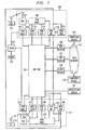
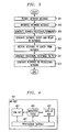
- FIG. 4 A block diagram of the embodiment of a multiple-protocol HLR is shown in FIG. 4.
- This embodiment of the MP HLR 101 includes an HLR for each type of wireless communication system and a server for each type of wireline network supported by the MP HLR 101.
- a GSM HLR 401 and an ANSI-41 HLR 403 are shown.
- Each of the HLRs 401 and 403 are interfaced to a mediation device 405.
- the mediation device (MD) 405 provides a number of functions, including generating network messages, translating network messages, and emulating GMSCs, VMSCs, and MCs.
- various tables including translation information are included in the MP HLR 101.
- the MD may also convert messages.
- the MD 405 may convert a Provide Roaming Number message to a Location Request message or a Routing Request message to a Send Routing Information message.
- the MP HLR 101 converts a Location Request message to a Provide Roaming Number message, and also converts a Send Routing Information message to a Routing Request message.
- the MP HLR 101 works with serving networks, i.e., networks where communication devices are currently registered, to update registration information, generate queries in response to requests, and route calls to users where they are located and in a manner that users access their communication devices, such as formatting profiles and messages according to the serving or terminating network's protocol.
- serving networks i.e., networks where communication devices are currently registered, to update registration information, generate queries in response to requests, and route calls to users where they are located and in a manner that users access their communication devices, such as formatting profiles and messages according to the serving or terminating network's protocol.
- the MP HLR 101 routes a call according to the protocol of the infrastructure device to which the call is directed.
- a provisioning gateway 407 preferably distributes user data for each of the devices within the MP HLR 101.
- the provisioning gateway 407 is interconnected to a database (not shown) that is part of or external to the MP HLR 101, or distributed among one or more of the MP HLR 101 components. Only two HLRs are shown part of the MP HLR in FIG. 4 for the sake of simplicity. If additional HLRs or home agents were to be added to the MP HLR, each such device would be interfaced to the mediation device 405 and the provisioning gateway 407.
- the database includes user information such as user profile, locations, and security information, such as the data stored in the database 201 as described above.
- Other stored data includes protocol types and addresses for communication devices, serving networks, and infrastructure devices such as gateway MSCs, terminating MSCs, visited MSCs, packet gateways, and internet protocol gateways. This data may be distributed as needed among the elements that require the information or may be stored for access as needed at various devices, such as the provisioning gateway 407 or the mediation device.
- FIG. 5 through FIG. 19 Various types of information flow and timing diagrams for the MP HLR 101 are shown in FIG. 5 through FIG. 19. These call flows may be utilized with the MP HLR of FIG. 2 or FIG. 4, although the flows of FIG. 5 through FIG. 17 are tailored to call flows within the MLP HLR 101 of FIG. 4 in order to show the interactions between the various HLRs 401 and 403 and the mediation device 405, which interactions may not take place in the MP HLR 101 of FIG. 2.
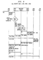
- a flowchart and timing diagram showing GSM registration in native mode is shown in FIG. 5.
- the native mode of a communication device is typically the same as the protocol type of the service center, message center, VMS, or GMSC associated with the communication device.
- the native mode In single-mode HLRs, the native mode is often the same as the protocol type of the HLR or home agent associated with the communication device.
- Foreign modes are modes that are not the native mode.
- a location update request is relayed from a mobile station to a GSM VMSC.
- the update location, including MSC number, VLR number, and MSC ID is relayed to the GSM HLR 401 of the MP HLR 101.
- the GSM HLR stores the MSC number and VLR number and sends an insert subscriber data message to the GSM GMSC, which sends an ACK to the GSM HLR 401.
- the GSM HLR 401 determines whether the mobile subscriber is a dual mode subscriber. When the mobile is not a dual mode subscriber, normal GSM processing is provided. When the mobile is a dual-mode mobile, the previous and new VMSC type of GSM is stored at the GSM HLR. An update location primitive (internal message) including an MSC type equal to GSM is sent to the mediation device, which converts the update location message to a registration notification message with an MSC type of GSM and relays that message to the ANSI HLR 403. The ANSI HLR stores the new VMSC type and the previous VMSC type and sends an ACK with no profile to the mediation device. A profile need not be sent because the mediation device has access to the profile information, thereby saving time and bandwidth by not sending the profile between the devices of the MP HLR 101. This ACK is relayed to the GSM HLR 401.
- the GSM HLR 401 determines if the previous VMSC type is of the HLR's type, i.e., GSM. If the previous VMSC type is GSM, a Cancel Location message is sent from the GSM HLR 401 to the previous GSM MSC, which deletes its VLR for the mobile 105.
- the process is completed, but if the previous VMSC type is ANSI and the native mode of the MS is not ANSI, the process is completed, but if the previous type is ANSI and the native mode is also ANSI, a cancel location request is sent from the GSM HLR 401 to the mediation device 405, which converts the cancel location to a registration cancellation that is sent to the previous ANSI MSC, which deletes its VLR for the mobile 105.
- the ANSI HLR also determines if a previous VMSC type is ANSI. If the previous VMSC type is not ANSI, the process is done, otherwise an ANSI registration cancellation is sent from the ANSI HLR 403 to the previous ANSI MSC, and the process is complete.
- FIG. 6 A flowchart and timing diagram showing ANSI registration in native mode is shown in FIG. 6.
- a registration request with an Electronic Serial Number (ESN) and Mobile Identification Number (MIN) is sent to an ANSI-136 GMSC, which sends an authentication request to the ANSI HLR 403 of the MP HLR 101.
- An ACK is sent back to the ANSI GMSC, which sends a registration notification including the ESN, MIN, and MSC ID to the ANSI HLR 403.
- the ANSI HLR stores the new MSC ID and sends an ACK with a profile to the GMSC.
- the ANSI HLR 403 determines whether the mobile is dual mode.
- the ANSI HLR 403 stores a new VMSC type equal to ANSI plus the previous MSC type.
- the ANSI HLR sends a registration notification with an MSC type of ANSI to the mediation device 405, which converts the registration notification to an update location message with an MSC type of ANSI to the GSM HLR for processing.
- the GSM HLR 401 stores the new VMSC type and the previous MSC type and sends an ACK without a profile ACK to the mediation device, which relays the ACK to the ANSI HLR 403.
- the GSM HLR determines whether the previous VMSC type is of its type, i.e., GSM.
- the process is complete, but if the previous VMSC type is GSM, a cancel location message is sent to the previous GSM MSC from the GSM HLR 401.
- the ANSI HLR determines if the previous VMSC type is ANSI, and if so, sends a registration cancellation message to the previous ANSI MSC.
- the ANSI HLR 403 sends a registration cancellation to the mediation device 405, which converts the registration cancellation to a cancel location request that is sent to the previous GSM MSC, and the process ends.
- FIG. 7 A flowchart and timing diagram showing call delivery originated in GSM and terminated in ANSI is shown in FIG. 7.
- An IAM including a called party number (PN) is sent to a GSM GMSC, which sends routing information to the GSM HLR 401 of the MP HLR 101.
- the GSM HLR 401 determines the VMSC type for the called party. When the type is GSM, normal GSM termination is provided. When the type is not GSM, the GSM HLR relays a provide roaming number messages with the GMSC address and type to the mediation device 405.
- the mediation device 405 stores the GMSC address and type, converts the provide roaming number message to a location request with the GMSC ID equal to the mediation device (MD), and sends the message to the ANSI HLR 403.
- MD mediation device
- the ANSI HLR sends a route request message to the ANSI VMSC with an MSC ID of MD indicating the mediation device 405.
- the ANSI VMSC sends an ACK including a TLDN or busy ACK to the ANSI HLR 403, which relays an ACK with a TLDN, absent, or busy to the mediation device 405.
- a PRN ACK with an MSRN, absent, or busy is relayed to the GSM HLR, which generates a SRI ACK including the MSRN or FTN and the IAM with the MSRN is relayed from the GSM GMSC to the ANSI VMSC processing to the mobile station.
- a late call forwarding invocation by the MS prevents the call from being completed from the ANSI VMSC.
- a redirection request including a redirection reason is relayed from the ANSI VMSC to the mediation device, which queries the GSM HLR for the FTN (Forward To Number).
- a resume call handling message including the FTN and forwarding reason is sent to the GSM GMSC, which sends an ACK to the mediation device, which sends an ACK to the ANSI VMSC, and the IAM with the FTN is sent to the FTN VMSC.
- This method is advantageous because, by granting the mediation device 405 access to the FTN, processing for call forwarded communications takes place at the originating GMSC, which saves trunking resources.
- the redirection reason may be relayed to the mediation device 405, which rejects the redirection request, causing a TRANUM (Transfer Number) request with a busy to be sent to the ANSI HLR.
- the ANSI HLR sends an ACK to the ANSI VMSC with the FTN, and the ANSI VMSC relays the IAM message with the FTN to the FTN VMSC.
- This method is advantageous because processing for call forwarded communications takes place between the MP HLR 101, and in particular the mediation device 405, and the terminating mobile switching center without having to involve the originating MSC, which may not have the ability to process a Resume.Call Handling (RCH).
- RCH Resume.Call Handling
- FIG. 8 A flowchart and timing diagram showing call delivery originated in ANSI and terminated in GSM is shown in FIG. 8.
- An IAM is relayed to an ANSI GMSC, which sends a location request to the ANSI HLR 403.
- the ANSI HLR 403 determines whether the VMSC type is ANSI or GSM. When the type is ANSI, normal ANSI termination is provided. When the type is GSM, a route request including the GMSC address and type is relayed to the mediation device 405.
- the mediation device 405 stores the GMSC address (which is useful for optimal routing for late call forwarding) and the GMSC type (which is useful for Intelligent Networking (IN) interaction), and sends an SRI to the GSM HLR 401.
- the GSM HLR 401 issues a PRN including a GMSC address equal to the MD and sends it to the GSM VMSC, which relays an ACK with the MSRN to the GSM HLR 401, which relays the ACK with MSRN to the mediation device 405.
- the mediation device converts the ACK with an MSRN to an ACK with a TLDN that is relayed to the ANSI HLR 401 and to the ANSI GMSC, which relays the IAM with the TLDN to the terminating GSM VMSC.
- a late call forwarding invocation by the MS prevents the call from being completed from the ANSI VMSC.
- the GSM VMSC sends an RCH (Resume Call Handling) including an FTN and forwarding reason to the mediation device 405 that converts the RCH to a redirection request including a redirection reason that is relayed to the ANSI GMSC, which requests a forward-to number from the ANSI HLR by sending a TRANUM request, and receives the FTN in the response, acknowledges the redirection request to the Mediation Device, and sends the [AM to the FTN VMSC.
- the MD acknowledges the RCH, and the process ends.
- This method is advantageous because, by granting the mediation device 405 access to the FTN, processing for call forwarded communications takes place between the MP HLR 101, and in particular the mediation device 405, and the originating gateway mobile switching center without having to involve an extra trunk between the originating MSC and the terminating MSC.
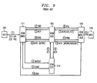
- FIG. 9 A block diagram with a signal flow for a GSM terminated call with terminating prepaid triggers, as known in the art, is shown in FIG. 9.
- a first mobile MS 1 105 elects to communicate with a second mobile MS2 119 that is a prepaid mobile user.
- the GSM GMSC 11 1 exchanges information with the GSM HLR 901, which communicates with the GSM SCP 114 to verify service for the particular user. Once the service is verified by the SCP 114, the HLR 901 proceeds with call handling through the GSM MSC/VLR, where the call is terminated with the second mobile 119.
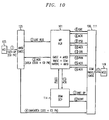
- FIG. 10 A block diagram with a signal flow for a GSM foreign mode terminated call utilizing an MP HLR is shown in FIG. 10.
- ANSI systems communicate with an SCP at the terminating MSC
- GSM systems communicate with an SCP at the (originating) GMSC.
- the first mobile 105 originates a call to a second mobile that utilizes prepaid service.
- the called party number (CD PN) is relayed to the ANSI GMSC 125, and a location request is relayed to the MP HLR 101.
- CD PN called party number
- the MP HLR 101 Because the MP HLR 101 knows the GMSC is ANSI, the VMSC is GSM, and the native mode of the mobile 105 is ANSI, the MP HLR 101 directs the call through the ANSI GMSC 111 to one of either the coupled terminating GSM VMSC/GMSC 109, 111 or a GMSC of the same protocol type as the VMSC, where normal GSM prepaid termination for the call takes place between the VMSC/GMSC 109/111, the MP HLR 101, and GSM SCP 114. Directing the call to the GMSC coupled with the VMSC has the advantage of saving trunking resources.
- the mediation device When the mediation device directs a call to a destination GMSC, the mediation device is able to send a called party number that may be different than the original called party number.
- the receiving GMSC must, however, recognize the called party number (which may include one of either a prefix followed by the original called party number or a different number).
- Directing the call to the GMSC of the same protocol type as the VMSC has the advantage that this GMSC may be in the same network as the ANSI GMSC 111 and is thus able to recognize one of either a prefix followed by the original called party number or a different number. Similarly (see FIG.
- the mediation device 405 when the mediation device 405 directs a Short Message to an SMSC/MC, the mediation device is able to both recognize and generate a called party number that may be different than the original called party number.
- the SMSC/MC and VMS must, however, recognize the called party number (which may include one of either a prefix followed by the original called party number or a different number).
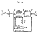
- FIG. 11 A block diagram with a signal flow for an ANSI foreign mode terminated call utilizing an MP HLR is shown in FIG. 11.
- the first mobile 105 originates a call, utilizing prepaid service, to a second mobile 119.
- An IAM is received at an ANSI MSC 123, which sends the IAM message to a GSM GMSC 111 that queries the database 101.
- the call is set up between the GSM GMSC 111, MP HLR 101, and GSM SCP (that determines payment authorization), and the GMSC 111 relays the IAM with the MSRN to the ANSI MSC that terminates the call with the second mobile 119.
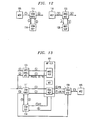
- FIG. 12 A block diagram with a signal flow for mobile originated prepaid calls is shown in FIG. 12.
- the mobile In the event that there is no combined SCP, the mobile is able to have multiple SCPs (one per each protocol) and communication between the SCPs is optional. In these cases, mobile originating prepaid service is utilized.
- the MP HLR 101 relays the call to the appropriate GMSC or ANSI terminating MSC which communicates with the appropriate SCP, as shown in Figures 13 and 14. In these cases, mobile terminating prepaid service is utilized.
- FIG. 13 A block diagram with a signal flow for mobile terminated prepaid call with GSM termination is shown in FIG. 13 for one of either native or foreign mode.
- operations with the MP HLR are shown for the case when the MP HLR 101 of FIG. 4 is utilized.
- the process (a) through (d) goes through the ANSI originating MSC 123 through the ANSI HLR 403 in the MP HLR 101, which routes the call ACK through the originating MSC 123 and to the GSM GMSC 111 for completion of processing via signal flow (1) through (11).
- the process originates (1) at the GSM GMSC 111.
- the call proceeds through setup between the GSM GMSC 11 1 and the GSM HLR 401, which authorizes service through the GSM SCP 114, and the call is terminated by the GSM MSC 109 to the second mobile 105.
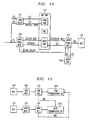
- FIG. 14 A block diagram of the signal flow for mobile terminated prepaid call with an ANSI termination is shown in FIG. 14 for one of either native or foreign mode.
- the call process (a) through (d) goes through the GSM GMSC 111 through the GSM HLR 401 and back through the GSM GMSC 111 to the ANSI originating MSC 123 for completion of processing via signal flow (1) through (9).
- the process begins (1) at the ANSI originating MSC 123.
- the ANSI originating MSC 123 sends a location request to the ANSI HLR 403, which sends a route request to the terminating ANSI MSC and the call flow proceeds as a normal ANSI originated and terminated call for a prepaid user.
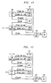
- a block diagram with a signal flow for a mobile originated SMS is shown in FIG. 15.
- a mobile originates SMS at its native MSC, which operates with the native protocol MC (Message Center), also known as a Service Center (SC) or an SMSC (Short Messaging Service Center), and terminates the service with a terminating MC 1501 or 1503 for that particular protocol.
- MC Message Center
- SC Service Center
- SMSC Short Messaging Service Center
- MC Short Messaging Service Center
- FIG. 16 and FIG. 17 A block diagram with a signal flow for a mobile terminated SMS using an MP HLR is shown in FIG. 16 and FIG. 17.
- an ANSI native mode SMS message is terminated in GSM foreign mode.
- the message is relayed to the ANSI HLR, which provides the mediation device 405 as MSC ID to the ANSI message center (MC) 129, which works with the mediation device 405 to generate an FSM (Forward Short Message) that is sent to the GSM MC 115.
- the GSM GMSC/MC works with the GSM HLR 401 to relay the message to the GSM MSC 109, which sends the message to the target mobile 105.
- a GSM native mode SMS message is terminated in ANSI foreign mode.
- the message is relayed to the GSM HLR, which provides the mediation device 405 as MSC ID to the GSM MC, which works with the mediation device 405 to generate an SMDPP (Short Message Direct Point to Point) that is sent to the ANSI MC.
- the ANSI MC works with the ANSI HLR to relay the message to the ANSI MSC, which sends the message to the target mobile 105.
- FIG. 18 A block diagram with a signal flow for an ANSI VMS (Voice Message System) Message Waiting Notification procedure is shown in FIG. 18.
- the MP HLR 101 generates a GSM mobile terminated SMS utilizing an MP HLR, in particular a mediation device, for an ANSI native mode terminating in GSM native mode.
- the ANSI VMS 130 sends an MWN (Message Waiting Notification) to an ANSI HLR, which communicates with the mediation device 405 to send an FSM to the GSM MC 115, that operates with the GSM HLR to relay the message to the appropriate GSM MSC 109 or GSM SGSN 113 for termination with the appropriate mobile 105 or 119.
- MWN Message Waiting Notification
- the MP HLR 101 knows the terminating MSC type, and is thus able to immediately direct the call to the appropriate message centers, thereby avoiding excess translation of messages through the MD 405.
- the GSM MC and/or ANSI MC functionality may be co-located within the MP HLR 101.
- FIG. 19 A block diagram with a signal flow for mobile originated and terminated SMS is shown in FIG. 19.
- An SMS message from an MS 105 to the GSM MSC 109 is routed to the GSM MC 115, regardless of the native mode of the Called Party.
- the GSM MC 115 routes the SMS message to the appropriate MC for termination, which is an ANSI MC 129 in this case.
- the ANSI MC 129 relays an FSM to the MD 405, which converts or translates the message to the desired protocol, e.g., from GSM to ANSI, and returns the MD address with the converted message.
- the ANSI MC 129 sends an SRI (with the MD address) to the ANSI HLR 403, which relays the message to the MD 405, which effectuates, for example via SMDPP or GHOST (GSM HOsted SMS Teleservice), termination from the ANSI MSC 123 to the end mobile 129.
- SRI with the MD address
- GHOST GSM HOsted SMS Teleservice
- the called party may have two MCs, one GSM and one ANSI.
- the VMSC routes the originating SMS message to the MC of its same protocol type, regardless of the subscriber's native mode. Whenever possible the originating MC routes to the called party's MC of the same protocol type.
- the call is routed to a mediation device 405 for protocol conversion to its native mode.
- the foreign mode MC sends the SMS message to an MD for protocol conversion to the terminating MSC.
- An MP HLR 101 is more efficient than an Interoperability Interworking Function (IIF) for a number of reasons. No mapping is required for profile information and less external network signaling is required for cross-technology registration because messages may be sent directly to the MP HLR 101.
- Call termination is more optimal because the originating MSC may query an HLR of the terminating technology through the mediation device, without having to route the call to the home network.
- Optimal routing particularly for late call forwarding, reduces international trunking in MP HLR 101 applications. SMS conversions are maximized at one, regardless of the originating or terminating user's protocol with the MP HLR 101.
- ANSI systems communicate with an SCP at the terminating MSC
- GSM systems communicate with an SCP at the (originating) GMSC
- the MP HLR 101 provides for termination triggers for ANSI subscribers operating in GSM foreign mode.
- the present invention provides a single HLR that supports multiple protocols of various types, including wireless and/or wireline and voice, data, and/or multimedia.
- the MP HLR replaces HLRs, home agents, and foreign agents for a number of network protocols.
- the MP HLR performs mobility/user location management, user authentication/security control, and user profile management functions for various different network protocols. These functions are required in traditional cellular networks, 3 rd generation wireless voice and data networks, and the internet, and have been previously deployed over separate functional entities.
- the MP HLR 101 embodies these functions of different entities in one entity by supporting multiple standard protocol interfaces.
- the MP HLR 101 promotes seamless evolution from today's first generation and second generation wireless networks based on a single HLR supporting a single network protocol to next generation wireless networks based on an HLR/IP server complex to future all-IP based wireless networks.
- the MP HLR 101 is advantageous in environments where users subscribe to more than one wireless and/or wireline service and enables seamless roaming of a multi-mode phone between different networks, e.g., between GSM and TDMA.
- a unified HLR provides cost reduction benefits to the service provider, such as savings gained from synchronizing and updating one HLR instead of many HLRs.
- the MP HLR 101 knows one of either the Gateway MSC or originating MSC type as well as the visiting MSC type. This knowledge allows the MP HLR 101 to direct the call to a Gateway MSC of the same type as the visiting MSC. Additionally, because the MP HLR 101 knows the true MSC on which the subscriber is registered, the MP HLR 101 may perform normal protocol procedures, e.g., call barring, call forwarding interactions with outgoing call barring, normal HLR restoration procedures, and regional zone subscription. The MP HLR 101 is able to offer a wider variety of services to multi-mode subscribers than just those that may be interworked. The subscriber is able to obtain true services according to whatever protocol the subscriber is currently registered.
- normal protocol procedures e.g., call barring, call forwarding interactions with outgoing call barring, normal HLR restoration procedures, and regional zone subscription.
- the MP HLR 101 is able to offer a wider variety of services to multi-mode subscribers than just those that may be interworked. The subscriber is able to obtain true services
- TABLE 2 comprises a list of acronyms utilized in the above description.
- AA Authentication, Authorization, and Accounting
- a AC Acknowledgment K Application Gateway API Application Programming Interface ATI Any Time Interrogation BOIC Barring of Outgoing International Calls
- BSS Base Station System
- CAMEL Customized Application for Mobile Network Enhanced Logic CDMA Code Division Multiple Access CF Call Forwarding
- CFB Call Forward Busy
- CFNRG Call Forwarding on Mobile Subscriber Not Reachable CONT
- EDGE Enhanced Data Rates for GPRS Evolution FTN Forward to Number GGSN Gateway GPRS Service Node GMSC Gateway Mobile Switching Center GPRS General Packet (Data) Radio Service
- GSM Group Special Mobile/Global System for Mobile Communications HDR High Data Rate HLR Home Location Register
- IAM Initial Address Message IN Intelligent Networking InitDP Initial Detection Point IP Internet Protocol LOC/ST Location/State MC
- Message Center MD Mediation Device M-IP Mobile IP MP HLR Multiple-Protocol Home Location Register MS
Description
- This invention relates to communication systems, including but not limited to home location register operation in communication systems.
- Various types of cellular communication systems are known to provide radio telephone service to a large number of mobile subscribers using a relatively small number of frequencies. Such service is provided by dividing a service area into a number of cells and reusing the frequencies in non-adjacent cells. This cellular principle has permitted a large growth in the amount of wireless telecommunications that may be carried over the allocated radio spectrum thus providing significant expansion in the number of wireless communication subscribers. Various different cellular protocols include analog, time division multiple access (TDMA), code division multiple access (CDMA), Global System for Mobile Communications (GSM).
- Similarly, various types of wireline systems and protocols provide different wireline services to a large number of users who typically utilize personal computers and other types of computing devices to access these services. Different wireline protocols and services include mobile or voice over IP (internet protocol), Authentication, Authorization, and Accounting (AAA), Session Initiation Protocol (SIP), and H.323 protocol that provides packet-based multimedia communication systems.
- In many wireless communication systems, Home Location Registers (HLRs) and Visitor Location Registers (VLRs) are used to handle mobility management. HLRs and VLRs potentially may reside anywhere in the network. An HLR contains profile information for each of its mobile subscribers and the address of the current VLRs for each mobile. Each Mobile Switching Center (MSC) has a VLR that tracks mobiles currently receiving service in the serving MSC's coverage area. Whenever a mobile enters an area served by a new VLR and registers there, the latter informs the mobile's HLR of the change in the mobile's location. In addition, the VLR downloads the service profile of the roaming mobile as well as other information necessary for call termination at the mobile. During call delivery, the location and profile information in the HLR is utilized to route incoming calls to the mobile.
- A universal location service register is known from WO-A-00 79 827. A method and system provide seamless wireless telecommunications for customers that move between disparate networks that use different protocols. At the location register unit level (i.e. the universal location service register), inputs into the universal location service register are shown going first to a network discriminator function to determine the type of network and the type of network protocol for each input message. Once that determination is made, the input is switched to a respective message handler of a number of message handlers for the network and network protocol type. This arrangement always takes time to do network discrimination, which in essence puts a discrimination time penalty on each input.
- An integrated home location register and IP-SS7 gateway is known from WO-A-00 74 409. The integrated home location register and IP-SS7 gateway is used for transmitting and receiving messages in a wireless communication network. The system comprises a processing system including a home location register (HLR) storing wireless user subscriber information. A first interface is in communication with a wireless office system (WOS) network for routing messages using a TCP/IP protocol. A second interface is in communication with a public land mobile network (PLMN) for routing messages using a message transfer part (MTP) protocol of signaling service number seven. A gateway function is operatively connected to the HLR and the first and second interfaces for controlling message transmission. This gateway is between a wireless network and an internet protocol-SS-7 of a public land-mobile network. The wireless part of this invention is called a wireless office system (WOS). The wireless office system is a dedicated and limited wireless protocol (e.g. ANSI 41) and
signaling services number 7 protocol system and stack operations. - As communication systems evolve and provide increased services, mobile users require more services, including roaming between and access to each different system. Issues regarding mobility management between these systems need to be resolved.
- Accordingly, there is a need for a method and apparatus to provide mobility management for users between multiple systems utilizing different protocols.
- A multiple-protocol home location register comprises a receiver for receiving, from a requesting network of at least two networks, a network request according to one of at least two network protocols. A processor, within the home location register, is arranged and constructed to generate network messages according to the at least two network protocols and to process the network request to obtain information requested by the network request. A transmitter, operably coupled to the processor, relays the requested information to at least one of the requesting network and a destination network.
-
- FIG. 1 is a block diagram showing multiple communication networks interfaced to a multiple-protocol HLR.
- FIG. 2 is a block diagram of a multiple-protocol HLR provided as an example for understanding the embodiment in accordance with the invention.
- FIG. 3 is a flowchart showing operation of a protocol gateway in a multiple-protocol HLR.
- FIG. 4 is a block diagram of an embodiment of a multiple-protocol HLR in accordance with the invention.
- FIG. 5 is a flowchart and timing diagram showing GSM registration in native mode in accordance with the invention.
- FIG. 6 is a flowchart and timing diagram showing ANSI registration in native mode in accordance with the invention.
- FIG. 7 is a flowchart and timing diagram showing call delivery originated in GSM and terminated in ANSI in accordance with the invention.
- FIG. 8 is a flowchart and timing diagram showing call delivery originated in ANSI and terminated in GSM in accordance with the invention.
- FIG. 9 is a block diagram with a signal flow for a GSM terminated call with terminating prepaid triggers.
- FIG. 10 is a block diagram with a signal flow for a GSM foreign mode terminated call utilizing a MP HLR in accordance with the invention.
- FIG. 11 is a block diagram with a signal flow for an ANSI foreign mode terminated call utilizing a MP HLR in accordance with the invention.
- FIG. 12 is a block diagram with a signal flow for a mobile originated prepaid calls in accordance with the invention.
- FIG. 13 and FIG. 14 each show a block diagram with a signal flow for a mobile terminated prepaid call utilizing a MP HLR in accordance with the invention.
- FIG. 15 is a block diagram with a signal flow for mobile originated short messaging service (SMS) in accordance with the invention.
- FIG. 16, FIG. 17, and FIG. 18 each show a block diagram with a signal flow for mobile terminated SMS utilizing a MP HLR in accordance with the invention.
- FIG. 19 is a block diagram with a signal flow for mobile originated and terminated SMS in accordance with the invention.
- The following describes an apparatus for and method of providing mobility management for users between multiple systems utilizing different protocols through use of a multiple-protocol home location register (MP HLR). The MP HLR comprises a processor, that is preferably distributed among various elements of the MP HLR although it may be a single processor, is arranged and constructed to generate network messages according to two or more network protocols and to process network requests and other messages to obtain information requested by two or more networks that support the two or more network protocols. An embodiment of an MP HLR is described herein. A example for understanding the the embodiment, utilizes protocol gateways that interpret network requests and generate, utilizing a common control procedures for multiple network protocols, queries to a database that provides a common source of data for all networks. The embodiment, which comprises an exemplary implementation, utilizes a mediation device that generates and/or translates network messages according to multiple different network protocols and is coupled to multiple HLRs, each supporting a different one of the multiple network protocols.
- A multiple-protocol home location register (HLR) comprises a first HLR arranged and constructed to provide a first network protocol and a second HLR arranged and constructed to provide a second network protocol. A mediation device is operably coupled to the first HLR and the second HLR and is arranged and constructed to generate network messages according to the first network protocol and the second network protocol, such that the multiple-protocol HLR provides HLR capability for a plurality of communication devices utilizing any of the first network protocol and the second network protocol.
- A system utilizing a multiple-protocol home location register comprises a first infrastructure device arranged and constructed to generate at least one query according to a first network protocol and a second infrastructure device arranged and constructed to function according to a second network protocol. The multiple-protocol home location register, operably coupled to the first infrastructure device and the second infrastructure device, wherein the multiple-protocol home location register is arranged and constructed to function according to the first network protocol and the second protocol, such that a call request according to the first network protocol and related to the at least one query is completed according to the second network protocol. At least one query is generated in response to a communication device request to communicate with a serving network. A profile for the communication device is sent to the serving network and the profile is formatted according to the serving network's protocol.
- A method comprises the steps of generating, by a first infrastructure device, a query according to a first network protocol and sending the first network protocol query to a multiple-protocol home location register functioning according to the first network protocol and a second network protocol. The multiple-protocol home location register processes the first network protocol query, thereby generating a second network protocol message. The second network protocol message is sent to a second infrastructure device functioning according to the second network protocol
- A block diagram of illustrating multiple communication networks interfaced to a multiple-protocol home location register (MP HLR) is shown in FIG. 1. At the center of the system is an
MP HLR 101 that is capable of supporting multiple different communication protocols. These protocols may be of many varied types, including wireless and/or wireline; voice, data, and/or multimedia; and circuit and/or packet basedThe MP HLR 101 performs mobility/user location management, user authentication/security control, and user profile management functions for various different network protocols. The various components of theMP HLR 101 may be geographically distributed. - One of the different types of protocols that interfaces with the
MP HLR 101 is Global System for Mobile Communications (GSM), as part of aGSM system 103 shown interfaced to theMP HLR 101. A mobile subscriber unit or mobile station (MS) 105 communicates with a base station system (BSS) 107 comprised of a plurality of base stations distributed throughout a plurality of coverage areas, each serviced by one of a plurality of Visited Mobile Switching Centers (VMSCs) 109. TheBSS 107 is operably coupled to theVMSCs 109, a Gateway Mobile Switching Center (GMSC) 111, and a Serving GPRS Service Node (SGSN) 113, all of which operate according to the GSM protocol. TheVMSCs 109 are coupled to a GSM Service Control Point (SCP) 114, a GSM Message Center (MC) 115, also known as an Short Message Service Center (SMSC), and a GSM Voice Message System (VMS) 116. TheGSM MC 115 andVMS 116 are operably coupled, and may be co-located. TheVMSCs 109,GMSC 111,SGSN 113,SCP 114, andMC 115 each connect to theMP HLR 101. Similarly, networks utilizing other types of wireless protocols may also be connected to the HLR. - An
ANSI communication system 117 and its interfaces to theMP HLR 101 are also shown in FIG. 1. ANSI-41 is utilized as the communication standard for infrastructure messages, and ANSI-136 is utilized as the communication standard for the air interface. AnMS 119 communications with an ANSIbase site system 121 comprised of a plurality of base stations distributed throughout a plurality of coverage areas, each serviced by one of a plurality of ANSI Visited Mobile Switching Centers (VMSCs) 123. TheBSS 121 is operably coupled toANSI VMSCs 123, an ANSI GMSC, which is known as an originating MSC, 125, and anANSI SGSN 127. TheANSI VMSCs 123 are coupled to an ANSI Service Control Point (SCP) 128, an ANSI MC (message center) 129, and anANSI VMS 130. TheGMSC 125,SGSN 127,VMSCs 123,SCP 128,MC 129, andVMS 130 each connect to theMP HLR 101. TheGSM MC 115 andANSI MC 129 are operably coupled. - The PSTN (public switch telephone network) 131 provides telephone service between wireline (conventional)
phones 133 and wireless devices. TheGSM GMSC 111,GSM MC 115,GSM VMS 116,ANSI GMSC 123,ANSI MC 129, andANSI VMS 130 are coupled to thePSTN 131 to enable wireline and wireless interconnections. - Wireline communication networks may also be coupled to the
MP HLR 101. TheMP HLR 101 provides home agent and foreign agent functionality for wireline networks. Such systems may be coupled through servers such as aAAA server 135, which provides authentication and related services utilizing the current de facto standard RADIUS, a Voice over IP (Internet Protocol)server 137 utilizing, for example, the Session Initiation Protocol (SIP) that provides an SIP registrar and proxy server, and an H.323protocol server 139. Each of theseservers data network 141, including wide area and/or local area networks that interconnect thecomputing devices servers application server 147 is shown connected to theMP HLR 101. Theapplication server 147 accesses user data in theMP HLR 101 for use with third party applications, such as provisioning, mobility service, and geo-location based applications. - Although examples of two wireless systems and three wireline networks are shown in FIG. 1, the multiple-protocol home location register of FIG. 1 is applicable to other wireless and wireline systems. Other applicable systems include, for example, Code Division Multiple Access (CDMA), High Data Rate (HDR) for CDMA data, Universal Mobile Telecommunications System (UMTS), and General Packet Radio Service (GPRS). Additional coupling between devices is possible, although not shown for the sake of simplicity.
- User or
subscriber devices - Infrastructure devices provide switching, packet relay, internet protocol, gateway, and/or interworking functions for their associated networks for both wireless and wireline networks. Examples of infrastructure devices include packet gateways, internet protocol gateways, GGSNs (Gateway GPRS Service Nodes), and MSCs, such as gateway MSCs, originating MSCs, and terminating MSCs.
- A block diagram of a multiple-protocol HLR provided as an example for understanding the embodiment in accordance with the invention is shown in FIG. 2. The
MP HLR 101 provides a service provider with unified user provisioning and service profile management interface, which is shared across protocols. The example of theMP HLR 101 includes common data types, a common source of data, and common control procedures that are centralized and projected in different formats to different network types to support user mobility across the different network types. Using this provisioning interface, a service provider may, for example, manage the profiles of different network types for a single user. - A
database component 201 comprisesuser locations 203, integrateduser profiles 205, andsecurity information 207 as well as access procedures used by adatabase manager 209 to access the data via one or more connections to thedatabase component 201. In the example thedatabase component 201 comprises at least one relational database. Optionally, thedatabase 201 may include information other than user locations, profiles, and security information, which data may not belong to any particular protocol or network, such as user data relating to other applications. Each data element includes information to sustain all network protocols that the MP HLR supports. Unified management ofuser location information 203 facilitates call delivery between different types of networks. Unified management ofsecurity information 207 facilitates authentication between different types of networks. - The integrated
user profile database 205 of theMP HLR 101 keeps the profile of users who have access capabilities to one or more network types. A service provider may uniformly manage the profiles of different network types for a single user through theMP HLR 101 The integrateduser profile database 205 also includes common user data, e.g., user name, user identification, and directory number for a user, and common service information, e.g., call forwarding directory numbers, that are shared. The integrateduser profile 205 in theMP HLR 101 further plays a broader role as a central repository of user and service data. Currently, various data is scattered between somewhat separate components of the network, such as the HLR, SCP, and AAA. TheMP HLR 101 promotes the simplification and consolidation of these complex interconnected components into a single repository of subscriber and service data, upon which feed multiple services and applications. - The
database manager 209 uses common procedures and exchanges common control commands and operations with one or more protocol gateways (PG), performs interworking functions across multiple different protocols, and manages, accesses, and updates data stored in thedatabase 201. Thedatabase manager 209 provides services as auser location database 203 manager, an integrateduser profile database 205 manager, and asecurity database 207 manager. Theuser location database 203 manager keeps track of the location of a user who may be at ce!lular terminals and/or at IP·terminals. The information is used for delivery of voice call, data session, and a short message to a user. Thesecurity database 207 manager manages user authentication control for wireless as well as IP systems. Theuser profile database 205 manager manages integrated user profile database and exposes the MP HLR database management interface to other functionalities of thedatabase manager 209. In the example, thedatabase manager 209 comprises a plurality of core servers that access thedatabase 201 through one or more connections. - The
database manager 209 anddatabase 201 may be considered a single database entity. When a PG queries the database, the PG sends the queries to thedatabase manager 209 to obtain the relevant information from the database. Thedatabase manager 209 may be a database application such as Database Views that provides, for example, SQL (Structured Query Language) or LDAP (Lightweight Directory Access Protocol) queries to thedatabase element 201. - The
database manager 209 interfaces with a number of protocol gateways. Each protocol gateway (PG) receives messages, including requests and queries, from a particular network. The PG may relay the message if no further processing is required, interpret and/or translate the message, and/or generate one or more queries that are sent to thedatabase 201 via thedatabase manager 209. All PGs utilize the same set of common procedures and commands when querying thedatabase manager 209. The PGs uses common procedures to convert network messages into common commands or operations, such as the examples shown in TABLE 1 below. In other words, the same set of common messages is utilized between each PG and thedatabase manager 209, regardless of the protocol supported by the PG. For example, theMP HLR 101 utilizes a Register Terminal message when an ANSI network sends a Registration Notification, when a GSM network sends an Update Location, and when an SIP network sends a Register (Location Lookup) message. In another example, theMP HLR 101 utilizes a Request Location message when an ANSI network sends a Location Request, when a GSM network sends a Send Routing Information message, and when an SIP network sends an Invite message. - In the example, each protocol gateway supports a single network and the protocol that network utilizes, and translates or interprets messages from that protocol to one of the common messages, such as commands or operations. Examples of PGs shown in FIG. 2 include a
GSM PG 211 supporting aGSM network 103, an ANSI-41PG 213 supporting an ANSI-41network 117, aAAA PG 215 supporting a AAA (RADIUS)server 135, anSIP PG 217 supporting aSIP server 137, and an H.323 PG supporting an H.323server 139. The various wireless networks and wire line servers that are shown are examples only, as additional networks, both wire line and wireless, voice, data (packet or circuit based), and/or multimedia, and so forth, may be additionally included in the MP HLR. - The
MP HLR 101 may also include one or more application gateways (AGs), such as the one 221 shown in FIG. 2. The AGs provide an interface through which information in theMP HLR 101 is accessed and notification of events, such as a mobile unit powering on or arrival of a mobile at a certain location, may be received. The AGs utilize the same common procedures, commands, and operations to access the database that the PGs utilize, including interpreting messages and requests from theapplication server 147 and generating queries to thedatabase manager 209 and relaying thedatabase 201 responses to theapplication server 147. - The
AGs 221 include one or more APIs (Application Programming Interfaces) that interface to one ormore application servers 147. The AGs may support management APIs and programming APIs for theMP HLR 101. Typically, AGs provide services through a non-standard interface. A provisioning AG provides service providers with an interface to provision user profiles through web-based interfaces as well as CORBA (Common Object Request Broker Architecture) based programming interface to the provider's provisioning center. Other types of interfaces such as LDAP may be sought when needed by introduction of another type of AG. The interface may also be used by an end-user to update the user's database entries though a web browser, e.g., supplementary service activation, call forwarding number update, and prepaid service updates, in which case the AG acts as a web server. A mobility service AG provides third party software vendors with programming API for mobility services. The API may be used to develop location-based service systems for users with cellular and/or internet access capabilities. The AG is an independent logical entity and employs theMP HLR 101 common operation interface to communicate with thedatabase manager 209 and integrated user profile database. - A flowchart showing operation of a protocol gateway in an MP HLR is shown in FIG. 3. At
step 301, a network message such as the examples shown in TABLE I below, as sourced by a network, is received. In the example, the protocol for the requesting network is terminated at the receivingstep 301 by the PG. Atstep 303, the network message is interpreted by the PG. The message is interpreted according to rules associated with the network protocol under which the PG operates. These rules and the network protocol may comply with a communication standard, such as, for example, ANSI-41, GSM, SIP, H.323, AAA, and Mobile IP (M-IP), that supports the network protocol. Atstep 305, a common procedure is followed, and as appropriate a common command or operation is generated. In the example the PG generates a common procedure or command, such as one shown in TABLE I, based on the interpretation of the network message atstep 303, and sends the common command or operation to thedatabase manager 209. Atstep 307, one or more database queries are generated based on the network message and relayed to thedatabase 201. In the example, thedatabase manager 209 generates one or more queries based on the common procedure or command (which is based on the network message), and sends the queries to thedatabase 201. Atstep 309, a response to the one or more queries is received from thedatabase 201. In the example, thedatabase manager 209 obtains the information from thedatabase 201 by queries particular to thedatabase 201 structures. Atstep 311, thedatabase manager 209 utilizes a common procedure to generate a response based on the response received from thedatabase 201. Atstep 313, the PG generates a response based on the response from thedatabase manager 209 and sends that response to the requesting network that received the network message. - An example of a call flow that utilizes multiple protocol gateways in an MP HLR is shown in FIG. 2. The numbers in circles represent the call flow, in chronological order, for call delivery through an
MP HLR 101. Although the example in FIG. 2 shows a GSM originating call that terminates in ANSI-41, calls may be delivered through any combination of originating and terminating networks. Generally, the call flow is described as follows. A message is received from a first network via a first protocol gateway. The message was generated, for example, because a call has been received for a mobile unit presently located in a second network. The message is processed according to a procedure common to the first protocol gateway and a second protocol gateway. At least one database query is generated based on the processed message The at least one database query is relayed to a database comprising data common to a first network associated with the first protocol gateway and a second network associated with the second protocol gateway. A response to the at least one database query is received, and a request to the second protocol gateway is generated. In the example, the response identifies a location for a mobile unit, both physical and logical, and this information identifies the second protocol gateway. A reply to the request to the second protocol gateway is received, which reply may include, for example, routing information within the second network. A message based on the reply is generated and relayed to the first protocol gateway. The information in the message, particularly routing information, is utilized to route a call to a mobile unit located in a coverage area of the second network. - More specifically, the call flow of FIG. 2 is described as follows. A (1) call, such as an IAM (Initial Address Message) or SIP invite, is delivered to the call processing entity governing the called party number. If the called party number is an SIP URL, the call is delivered to an SIP proxy. If the called party number is a GSM or ANSI-41 wireless phone number, the call is delivered to a GSM GMSC or an ANSI-41 home MSC, respectively. An appropriate (2) location query message, such as a Location Request for ANSI, a Send Routing Information for GSM (as shown), or an SIP location lookup, is sent to the
corresponding PG 211 from the originating network. ThePG 211 translates the location query message into a (3) request location message that is relayed to thedatabase manager 209. Thedatabase manager 209 processes the request into a (4A) database query that is relayed to thedatabase 201, which determines the requested information and relays that (4B) requested information back to thedatabase manager 209. - The
database manager 209 looks up the user's location database to determine the current location of the user. Thedatabase manager 209 sends a (5) request route information message through thePG 213 that manages the network where the user is currently located or roaming, i.e., the terminating network. ThatPG 213 contacts an entity within the terminating network to (6) obtain routing information for that user For example, a Route Request is sent to an ANSI MSC (as shown in the example in FIG. 2) or a Provide Roaming Number (PRN) message is sent to a GSM MSC. A (7) routing return message, such as a route request with a TLDN (Temporary Location Directory Number) from an ANSI-41 MSC (as shown in FIG. 2), a PRN ACK with an MSRN (Mobile Subscriber Roaming Number) from GSM MSC, or routing information used to reach a signaling and media gateway complex that has SIP user agent functionality for a call from an SIP network via the PSTN, is returned to the terminatingPG 213. ThePG 213 processes the routing return message into a (8) requested route information response that is relayed to thedatabase manager 209. Thedatabase manager 209 processes the requested route information response into a (9) request location response, including the relevant information from the routing return message, and sends the request location response to thePG 211 for originating call processing entity. ThePG 211 converts the request location response to an appropriate (10) network response, such as a location request for ANSI, an SRI ACK for GSM (as shown in FIG. 2), or an SIP location lookup response for SIP. The originating network relays the (11) call (IAM or SIP invite) to a device in the terminating network that delivers the (12) call to the appropriate end user. - A block diagram of the embodiment of a multiple-protocol HLR is shown in FIG. 4. This embodiment of the
MP HLR 101 includes an HLR for each type of wireless communication system and a server for each type of wireline network supported by theMP HLR 101. In the particular example shown, aGSM HLR 401 and an ANSI-41HLR 403 are shown. Each of theHLRs mediation device 405. The mediation device (MD) 405 provides a number of functions, including generating network messages, translating network messages, and emulating GMSCs, VMSCs, and MCs. As part of the translation function, various tables including translation information are included in theMP HLR 101. An example of such a translation table is shown in TABLE I, which translates messages between GSM and ANSI-41/ANSI-136. The MD may also convert messages. For example, theMD 405 may convert a Provide Roaming Number message to a Location Request message or a Routing Request message to a Send Routing Information message. When looking at conversion external to theMP HLR 101, theMP HLR 101 converts a Location Request message to a Provide Roaming Number message, and also converts a Send Routing Information message to a Routing Request message. TheMP HLR 101 works with serving networks, i.e., networks where communication devices are currently registered, to update registration information, generate queries in response to requests, and route calls to users where they are located and in a manner that users access their communication devices, such as formatting profiles and messages according to the serving or terminating network's protocol. TheMP HLR 101 routes a call according to the protocol of the infrastructure device to which the call is directed. - In the embodiment, a
provisioning gateway 407 preferably distributes user data for each of the devices within theMP HLR 101. Theprovisioning gateway 407 is interconnected to a database (not shown) that is part of or external to theMP HLR 101, or distributed among one or more of theMP HLR 101 components. Only two HLRs are shown part of the MP HLR in FIG. 4 for the sake of simplicity. If additional HLRs or home agents were to be added to the MP HLR, each such device would be interfaced to themediation device 405 and theprovisioning gateway 407. The database includes user information such as user profile, locations, and security information, such as the data stored in thedatabase 201 as described above. Other stored data includes protocol types and addresses for communication devices, serving networks, and infrastructure devices such as gateway MSCs, terminating MSCs, visited MSCs, packet gateways, and internet protocol gateways. This data may be distributed as needed among the elements that require the information or may be stored for access as needed at various devices, such as theprovisioning gateway 407 or the mediation device. - Various types of information flow and timing diagrams for the
MP HLR 101 are shown in FIG. 5 through FIG. 19. These call flows may be utilized with the MP HLR of FIG. 2 or FIG. 4, although the flows of FIG. 5 through FIG. 17 are tailored to call flows within theMLP HLR 101 of FIG. 4 in order to show the interactions between thevarious HLRs mediation device 405, which interactions may not take place in theMP HLR 101 of FIG. 2. - A flowchart and timing diagram showing GSM registration in native mode is shown in FIG. 5. The native mode of a communication device is typically the same as the protocol type of the service center, message center, VMS, or GMSC associated with the communication device. In single-mode HLRs, the native mode is often the same as the protocol type of the HLR or home agent associated with the communication device. Foreign modes are modes that are not the native mode. A location update request is relayed from a mobile station to a GSM VMSC. The update location, including MSC number, VLR number, and MSC ID is relayed to the
GSM HLR 401 of theMP HLR 101. The GSM HLR stores the MSC number and VLR number and sends an insert subscriber data message to the GSM GMSC, which sends an ACK to theGSM HLR 401. - The
GSM HLR 401 determines whether the mobile subscriber is a dual mode subscriber. When the mobile is not a dual mode subscriber, normal GSM processing is provided. When the mobile is a dual-mode mobile, the previous and new VMSC type of GSM is stored at the GSM HLR. An update location primitive (internal message) including an MSC type equal to GSM is sent to the mediation device, which converts the update location message to a registration notification message with an MSC type of GSM and relays that message to theANSI HLR 403. The ANSI HLR stores the new VMSC type and the previous VMSC type and sends an ACK with no profile to the mediation device. A profile need not be sent because the mediation device has access to the profile information, thereby saving time and bandwidth by not sending the profile between the devices of theMP HLR 101. This ACK is relayed to theGSM HLR 401. - Upon receipt of the ACK, the
GSM HLR 401 determines if the previous VMSC type is of the HLR's type, i.e., GSM. If the previous VMSC type is GSM, a Cancel Location message is sent from theGSM HLR 401 to the previous GSM MSC, which deletes its VLR for the mobile 105. Optionally, if the previous VMSC type is ANSI and the native mode of the MS is not ANSI, the process is completed, but if the previous type is ANSI and the native mode is also ANSI, a cancel location request is sent from theGSM HLR 401 to themediation device 405, which converts the cancel location to a registration cancellation that is sent to the previous ANSI MSC, which deletes its VLR for the mobile 105. The ANSI HLR also determines if a previous VMSC type is ANSI. If the previous VMSC type is not ANSI, the process is done, otherwise an ANSI registration cancellation is sent from theANSI HLR 403 to the previous ANSI MSC, and the process is complete. - A flowchart and timing diagram showing ANSI registration in native mode is shown in FIG. 6. A registration request with an Electronic Serial Number (ESN) and Mobile Identification Number (MIN) is sent to an ANSI-136 GMSC, which sends an authentication request to the
ANSI HLR 403 of theMP HLR 101. An ACK is sent back to the ANSI GMSC, which sends a registration notification including the ESN, MIN, and MSC ID to theANSI HLR 403. The ANSI HLR stores the new MSC ID and sends an ACK with a profile to the GMSC. TheANSI HLR 403 determines whether the mobile is dual mode. When the mobile is not dual mode, normal ANSI processing for the registration takes place, otherwise theANSI HLR 403 stores a new VMSC type equal to ANSI plus the previous MSC type. The ANSI HLR sends a registration notification with an MSC type of ANSI to themediation device 405, which converts the registration notification to an update location message with an MSC type of ANSI to the GSM HLR for processing. TheGSM HLR 401 stores the new VMSC type and the previous MSC type and sends an ACK without a profile ACK to the mediation device, which relays the ACK to theANSI HLR 403. The GSM HLR determines whether the previous VMSC type is of its type, i.e., GSM. If the previous VMSC type is not GSM, the process is complete, but if the previous VMSC type is GSM, a cancel location message is sent to the previous GSM MSC from theGSM HLR 401. The ANSI HLR determines if the previous VMSC type is ANSI, and if so, sends a registration cancellation message to the previous ANSI MSC. Optionally, when the previous VMSC type is GSM and if mobile is in its native mode, there is no further processing, but if the mobile's native mode is GSM, theANSI HLR 403 sends a registration cancellation to themediation device 405, which converts the registration cancellation to a cancel location request that is sent to the previous GSM MSC, and the process ends. - A flowchart and timing diagram showing call delivery originated in GSM and terminated in ANSI is shown in FIG. 7. An IAM including a called party number (PN) is sent to a GSM GMSC, which sends routing information to the
GSM HLR 401 of theMP HLR 101. TheGSM HLR 401 determines the VMSC type for the called party. When the type is GSM, normal GSM termination is provided. When the type is not GSM, the GSM HLR relays a provide roaming number messages with the GMSC address and type to themediation device 405. Themediation device 405 stores the GMSC address and type, converts the provide roaming number message to a location request with the GMSC ID equal to the mediation device (MD), and sends the message to theANSI HLR 403. - The ANSI HLR sends a route request message to the ANSI VMSC with an MSC ID of MD indicating the
mediation device 405. The ANSI VMSC sends an ACK including a TLDN or busy ACK to theANSI HLR 403, which relays an ACK with a TLDN, absent, or busy to themediation device 405. A PRN ACK with an MSRN, absent, or busy is relayed to the GSM HLR, which generates a SRI ACK including the MSRN or FTN and the IAM with the MSRN is relayed from the GSM GMSC to the ANSI VMSC processing to the mobile station. In this example, a late call forwarding invocation by the MS prevents the call from being completed from the ANSI VMSC. In one embodiment, a redirection request including a redirection reason is relayed from the ANSI VMSC to the mediation device, which queries the GSM HLR for the FTN (Forward To Number). A resume call handling message including the FTN and forwarding reason is sent to the GSM GMSC, which sends an ACK to the mediation device, which sends an ACK to the ANSI VMSC, and the IAM with the FTN is sent to the FTN VMSC. This method is advantageous because, by granting themediation device 405 access to the FTN, processing for call forwarded communications takes place at the originating GMSC, which saves trunking resources. Alternatively, the redirection reason may be relayed to themediation device 405, which rejects the redirection request, causing a TRANUM (Transfer Number) request with a busy to be sent to the ANSI HLR. The ANSI HLR sends an ACK to the ANSI VMSC with the FTN, and the ANSI VMSC relays the IAM message with the FTN to the FTN VMSC. This method is advantageous because processing for call forwarded communications takes place between theMP HLR 101, and in particular themediation device 405, and the terminating mobile switching center without having to involve the originating MSC, which may not have the ability to process a Resume.Call Handling (RCH). - A flowchart and timing diagram showing call delivery originated in ANSI and terminated in GSM is shown in FIG. 8. An IAM is relayed to an ANSI GMSC, which sends a location request to the
ANSI HLR 403. TheANSI HLR 403 determines whether the VMSC type is ANSI or GSM. When the type is ANSI, normal ANSI termination is provided. When the type is GSM, a route request including the GMSC address and type is relayed to themediation device 405. Themediation device 405 stores the GMSC address (which is useful for optimal routing for late call forwarding) and the GMSC type (which is useful for Intelligent Networking (IN) interaction), and sends an SRI to theGSM HLR 401. TheGSM HLR 401 issues a PRN including a GMSC address equal to the MD and sends it to the GSM VMSC, which relays an ACK with the MSRN to theGSM HLR 401, which relays the ACK with MSRN to themediation device 405. The mediation device converts the ACK with an MSRN to an ACK with a TLDN that is relayed to theANSI HLR 401 and to the ANSI GMSC, which relays the IAM with the TLDN to the terminating GSM VMSC. In this example, a late call forwarding invocation by the MS prevents the call from being completed from the ANSI VMSC. The GSM VMSC sends an RCH (Resume Call Handling) including an FTN and forwarding reason to themediation device 405 that converts the RCH to a redirection request including a redirection reason that is relayed to the ANSI GMSC, which requests a forward-to number from the ANSI HLR by sending a TRANUM request, and receives the FTN in the response, acknowledges the redirection request to the Mediation Device, and sends the [AM to the FTN VMSC. The MD acknowledges the RCH, and the process ends. This method is advantageous because, by granting themediation device 405 access to the FTN, processing for call forwarded communications takes place between theMP HLR 101, and in particular themediation device 405, and the originating gateway mobile switching center without having to involve an extra trunk between the originating MSC and the terminating MSC. - A block diagram with a signal flow for a GSM terminated call with terminating prepaid triggers, as known in the art, is shown in FIG. 9. A first
mobile MS 1 105 elects to communicate with a secondmobile MS2 119 that is a prepaid mobile user. In this example, theGSM GMSC 11 1 exchanges information with theGSM HLR 901, which communicates with theGSM SCP 114 to verify service for the particular user. Once the service is verified by theSCP 114, theHLR 901 proceeds with call handling through the GSM MSC/VLR, where the call is terminated with the second mobile 119. - A block diagram with a signal flow for a GSM foreign mode terminated call utilizing an MP HLR is shown in FIG. 10. For prepaid users, ANSI systems communicate with an SCP at the terminating MSC, whereas GSM systems communicate with an SCP at the (originating) GMSC. In the example shown, the first mobile 105 originates a call to a second mobile that utilizes prepaid service. The called party number (CD PN) is relayed to the
ANSI GMSC 125, and a location request is relayed to theMP HLR 101. Because theMP HLR 101 knows the GMSC is ANSI, the VMSC is GSM, and the native mode of the mobile 105 is ANSI, theMP HLR 101 directs the call through theANSI GMSC 111 to one of either the coupled terminating GSM VMSC/GMSC GMSC 109/111, theMP HLR 101, andGSM SCP 114. Directing the call to the GMSC coupled with the VMSC has the advantage of saving trunking resources. When the mediation device directs a call to a destination GMSC, the mediation device is able to send a called party number that may be different than the original called party number. The receiving GMSC must, however, recognize the called party number (which may include one of either a prefix followed by the original called party number or a different number). Directing the call to the GMSC of the same protocol type as the VMSC has the advantage that this GMSC may be in the same network as theANSI GMSC 111 and is thus able to recognize one of either a prefix followed by the original called party number or a different number. Similarly (see FIG. 16, 17, and 18), when themediation device 405 directs a Short Message to an SMSC/MC, the mediation device is able to both recognize and generate a called party number that may be different than the original called party number. The SMSC/MC and VMS must, however, recognize the called party number (which may include one of either a prefix followed by the original called party number or a different number). - A block diagram with a signal flow for an ANSI foreign mode terminated call utilizing an MP HLR is shown in FIG. 11. In this situation, the first mobile 105 originates a call, utilizing prepaid service, to a second mobile 119. An IAM is received at an
ANSI MSC 123, which sends the IAM message to aGSM GMSC 111 that queries thedatabase 101. The call is set up between theGSM GMSC 111,MP HLR 101, and GSM SCP (that determines payment authorization), and theGMSC 111 relays the IAM with the MSRN to the ANSI MSC that terminates the call with the second mobile 119. - A block diagram with a signal flow for mobile originated prepaid calls is shown in FIG. 12. In the event that there is no combined SCP, the mobile is able to have multiple SCPs (one per each protocol) and communication between the SCPs is optional. In these cases, mobile originating prepaid service is utilized. For mobile terminated prepaid calls, the
MP HLR 101 relays the call to the appropriate GMSC or ANSI terminating MSC which communicates with the appropriate SCP, as shown in Figures 13 and 14. In these cases, mobile terminating prepaid service is utilized. - A block diagram with a signal flow for mobile terminated prepaid call with GSM termination is shown in FIG. 13 for one of either native or foreign mode. In this example, operations with the MP HLR are shown for the case when the
MP HLR 101 of FIG. 4 is utilized. When the terminating mobile operates in foreign mode compared to the originating MSC, the process (a) through (d) goes through theANSI originating MSC 123 through theANSI HLR 403 in theMP HLR 101, which routes the call ACK through the originatingMSC 123 and to theGSM GMSC 111 for completion of processing via signal flow (1) through (11). When the mobile operates in its native GSM mode, the process originates (1) at theGSM GMSC 111. The call proceeds through setup between theGSM GMSC 11 1 and theGSM HLR 401, which authorizes service through theGSM SCP 114, and the call is terminated by theGSM MSC 109 to the second mobile 105. - A block diagram of the signal flow for mobile terminated prepaid call with an ANSI termination is shown in FIG. 14 for one of either native or foreign mode. When the terminating mobile operates in foreign mode compared to the originating MSC, the call process (a) through (d) goes through the
GSM GMSC 111 through theGSM HLR 401 and back through theGSM GMSC 111 to theANSI originating MSC 123 for completion of processing via signal flow (1) through (9). When the mobile operates in its native mode, the process begins (1) at theANSI originating MSC 123. TheANSI originating MSC 123 sends a location request to theANSI HLR 403, which sends a route request to the terminating ANSI MSC and the call flow proceeds as a normal ANSI originated and terminated call for a prepaid user. - A block diagram with a signal flow for a mobile originated SMS is shown in FIG. 15. A mobile originates SMS at its native MSC, which operates with the native protocol MC (Message Center), also known as a Service Center (SC) or an SMSC (Short Messaging Service Center), and terminates the service with a terminating
MC message center - A block diagram with a signal flow for a mobile terminated SMS using an MP HLR is shown in FIG. 16 and FIG. 17. In the example of FIG. 16, an ANSI native mode SMS message, is terminated in GSM foreign mode. The message is relayed to the ANSI HLR, which provides the
mediation device 405 as MSC ID to the ANSI message center (MC) 129, which works with themediation device 405 to generate an FSM (Forward Short Message) that is sent to theGSM MC 115. The GSM GMSC/MC works with theGSM HLR 401 to relay the message to theGSM MSC 109, which sends the message to the target mobile 105. In the example of FIG. 17, a GSM native mode SMS message is terminated in ANSI foreign mode. The message is relayed to the GSM HLR, which provides themediation device 405 as MSC ID to the GSM MC, which works with themediation device 405 to generate an SMDPP (Short Message Direct Point to Point) that is sent to the ANSI MC. The ANSI MC works with the ANSI HLR to relay the message to the ANSI MSC, which sends the message to the target mobile 105. - A block diagram with a signal flow for an ANSI VMS (Voice Message System) Message Waiting Notification procedure is shown in FIG. 18. The
MP HLR 101 generates a GSM mobile terminated SMS utilizing an MP HLR, in particular a mediation device, for an ANSI native mode terminating in GSM native mode. TheANSI VMS 130 sends an MWN (Message Waiting Notification) to an ANSI HLR, which communicates with themediation device 405 to send an FSM to theGSM MC 115, that operates with the GSM HLR to relay the message to theappropriate GSM MSC 109 orGSM SGSN 113 for termination with the appropriate mobile 105 or 119. In the situations shown in FIG. 16 and FIG. 17, theMP HLR 101 knows the terminating MSC type, and is thus able to immediately direct the call to the appropriate message centers, thereby avoiding excess translation of messages through theMD 405. The GSM MC and/or ANSI MC functionality may be co-located within theMP HLR 101. - A block diagram with a signal flow for mobile originated and terminated SMS is shown in FIG. 19. An SMS message from an
MS 105 to theGSM MSC 109 is routed to theGSM MC 115, regardless of the native mode of the Called Party. TheGSM MC 115 routes the SMS message to the appropriate MC for termination, which is anANSI MC 129 in this case. TheANSI MC 129 relays an FSM to theMD 405, which converts or translates the message to the desired protocol, e.g., from GSM to ANSI, and returns the MD address with the converted message. TheANSI MC 129 sends an SRI (with the MD address) to theANSI HLR 403, which relays the message to theMD 405, which effectuates, for example via SMDPP or GHOST (GSM HOsted SMS Teleservice), termination from theANSI MSC 123 to the end mobile 129. Utilizing theMP HLR 101 in this manner maximizes SMS conversion to one conversion for any call, no matter what the native protocol, originating protocol, or terminating protocol is - With the MP HLR solution, the called party may have two MCs, one GSM and one ANSI. The VMSC routes the originating SMS message to the MC of its same protocol type, regardless of the subscriber's native mode. Whenever possible the originating MC routes to the called party's MC of the same protocol type. When the called party is not a dual mode subscriber, the call is routed to a
mediation device 405 for protocol conversion to its native mode. Likewise, if the dual mode called party is operating in foreign mode, the foreign mode MC sends the SMS message to an MD for protocol conversion to the terminating MSC. - An
MP HLR 101 is more efficient than an Interoperability Interworking Function (IIF) for a number of reasons. No mapping is required for profile information and less external network signaling is required for cross-technology registration because messages may be sent directly to theMP HLR 101. Call termination is more optimal because the originating MSC may query an HLR of the terminating technology through the mediation device, without having to route the call to the home network. Optimal routing, particularly for late call forwarding, reduces international trunking inMP HLR 101 applications. SMS conversions are maximized at one, regardless of the originating or terminating user's protocol with theMP HLR 101. Although ANSI systems communicate with an SCP at the terminating MSC, and GSM systems communicate with an SCP at the (originating) GMSC, theMP HLR 101 provides for termination triggers for ANSI subscribers operating in GSM foreign mode. - The present invention provides a single HLR that supports multiple protocols of various types, including wireless and/or wireline and voice, data, and/or multimedia. The MP HLR replaces HLRs, home agents, and foreign agents for a number of network protocols. The MP HLR performs mobility/user location management, user authentication/security control, and user profile management functions for various different network protocols. These functions are required in traditional cellular networks, 3rd generation wireless voice and data networks, and the internet, and have been previously deployed over separate functional entities. The
MP HLR 101 embodies these functions of different entities in one entity by supporting multiple standard protocol interfaces. With multiple-protocol support, theMP HLR 101 promotes seamless evolution from today's first generation and second generation wireless networks based on a single HLR supporting a single network protocol to next generation wireless networks based on an HLR/IP server complex to future all-IP based wireless networks. TheMP HLR 101 is advantageous in environments where users subscribe to more than one wireless and/or wireline service and enables seamless roaming of a multi-mode phone between different networks, e.g., between GSM and TDMA. A unified HLR provides cost reduction benefits to the service provider, such as savings gained from synchronizing and updating one HLR instead of many HLRs. - Additionally, the
MP HLR 101 knows one of either the Gateway MSC or originating MSC type as well as the visiting MSC type. This knowledge allows theMP HLR 101 to direct the call to a Gateway MSC of the same type as the visiting MSC. Additionally, because theMP HLR 101 knows the true MSC on which the subscriber is registered, theMP HLR 101 may perform normal protocol procedures, e.g., call barring, call forwarding interactions with outgoing call barring, normal HLR restoration procedures, and regional zone subscription. TheMP HLR 101 is able to offer a wider variety of services to multi-mode subscribers than just those that may be interworked. The subscriber is able to obtain true services according to whatever protocol the subscriber is currently registered. - The present invention may be embodied in other specific forms without departing from its essential characteristics. The described embodiments are to be considered in all respects only as illustrative and not restrictive. The scope of the invention is, therefore, indicated by the appended claims rather than by the foregoing description.
TABLE 1 MP HLR COMMON OPERATION ANSI-41/ANSI-136 GSM Register Terminal Registration Notification Update Location Deregister Terminal MS Inactive Purge MS Request Location SMS Request Send Routing Info for GPRS/SM Request Location Location Request Provide Roaming Number Perform DB Operation Feature Request Register SS Erase SS Active SS Deactive SS Interrogate SS Register Password Cancel Terminal Regis. Registration Cancellation Cancel Location Retrieve Profile Qualification Directive Insert Subscriber Data Insert Profile Qualification Directive Delete Subscriber Data Request Route Info. Route Request Send Routing Info. Notify Events OAM OAM Report Terminal Status (Registration Notification) Ready for SM Report SM Delivery Status Failure Report Notify Terminal Status SMS Notification Note MS GPRS Present Change Alert Service Center Obtain Authorization Info. Authorization Request Send Authentication Authorization Directive Information Verify Authorization Info. Authorization Request challenge BS Challenge - TABLE 2 comprises a list of acronyms utilized in the above description.
TABLE 2 AA Authentication, Authorization, and Accounting A AC Acknowledgment K AG Application Gateway API Application Programming Interface ATI Any Time Interrogation BOIC Barring of Outgoing International Calls BSS Base Station System CAMEL Customized Application for Mobile Network Enhanced Logic CDMA Code Division Multiple Access CF Call Forwarding CFB Call Forward Busy CFNRG Call Forwarding on Mobile Subscriber Not Reachable CONT Continue EDGE Enhanced Data Rates for GPRS Evolution FTN Forward to Number GGSN Gateway GPRS Service Node GMSC Gateway Mobile Switching Center GPRS General Packet (Data) Radio Service GSM Group Special Mobile/Global System for Mobile Communications HDR High Data Rate HLR Home Location Register IAM Initial Address Message IN Intelligent Networking InitDP Initial Detection Point IP Internet Protocol LOC/ST Location/State MC Message Center MD Mediation Device M-IP Mobile IP MP HLR Multiple-Protocol Home Location Register MS Mobile Station MSC Mobile Switching Center MSRN Mobile Subscribing Roaming Number OAM PG Protocol Gateway Party Number PN Party Number PRN Provide Roaming Number PSI Provide Subscriber Information PSTN Public Switch Telephone Network RCH Resume Call Handling SC Service Center SCP Service Control Point SGSN Serving GPRS Service Node SIP Session Initiation Protocol SMSC Short Message Service Center SPA Service Package Application SRI Send Routing Information SS7 Standard Signaling System 7TDMA Time Division Multiple Access TLDN Temporary Location Directory Number UMTS Universal Mobile Telecommunications System VLR Visitor Location Register VMS Voice Message System VMSC Visited Mobile Switching Center
Claims (9)
- A multiple-protocol home location register (101) connected to a plurality of networks that serve wireless and/or wireline stations through employment of a plurality of wireless communication protocols and/or wireline communication protocols, characterized in that the multiple-protocol home location register comprises:a plurality of home location registers with a home location register for each type of wireless communication protocol served by the multiple protocol home location register;a mediation device (405) interfaced to each of the plurality of home location registers (401, 403);the mediation device is adapted to translate network messages from a first wireless communication protocol, of the plurality of wireless communication protocols, to a second wireless communication protocol, of the plurality of wireless communication protocols, using look-up tables to call from a first station using the first wireless communication protocol to a second station using the second wireless communication protocol;wherein the mediation device is adapted to emulate at least one of a group of network equipment: a gateway mobile switching center, a visited mobile switching center, and a message center as the mediation device mediates between the first wireless communication protocol and the second wireless communication protocol.
- The multiple-protocol home location register of claim 1, wherein the second station is a wireline station.
- The multiple-protocol home location register of claim 1, wherein the wherein the second station is a wireless station.
- The multiple-protocol home location register of claim 1, 2 or 3, further characterized in that the plurality of wireless communication protocols comprise global system for mobile communications (401) and American National Standards Institute 41 (403).
- The multiple protocol home location register of claim 1, 2, 3, or 4 wherein the mediation device receives a short message service message from a mobile station in one protocol and the message terminates in a different protocol in which case the mediation device provides an interworking and interoperability function to convert the message to the different protocol and relays the converted message to a terminating message center (1501 or 1503).
- The multiple protocol home location register of claim 1, wherein the mediation device has a processor and memory to provide mediation between different communication protocols.
- A method for call delivery of a call using one wireless communication protocol to originate the call and using a second wireless communication protocol to terminate the call through a use of a multiple protocol home location register (101), characterized by:sending an initial address message which includes a called party number to a mobile switching center in the first wireless communication protocol;in response to the initial address message, sending routing information in the first wireless communication protocol to a first home location register (401) of the multiple protocol home location register (101);determining a visited mobile switching center type for the called party by the first home location register;if the visited mobile switching center type is the same wireless communication protocol type as the first wireless communication protocol type, providing normal first wireless communication protocol termination to the called party;if the visited mobile switching center type is not the same wireless communication protocol type as the first wireless communication protocol type, sending a provide roaming number message with the initial mobile switching center address and wireless communication protocol type to a mediation device (405);storing the mobile switching center address and wireless communication protocol type by the mediation device;converting by the mediation device the provide roaming number message to a location request message in a second wireless communication protocol, the location request message having a mobile switching center identification indicating the mediation device;sending the location request message in a second wireless communication protocol from the mediation device to a second home location register (403);sending a route request message by the second home location register to a second visited mobile switching center in the second wireless communication protocol, the route message request having a mobile switching center identification indicating the mediation device;in response to the route request message, sending an acknowledgement message in the second wireless communication protocol by the second visited mobile switching center including a temporary location directory number to the second home location register,in response to the acknowledgement, relaying the acknowledgement with the temporary location directory number to the mediation device;sending a provide roaming number acknowledgement with a mobile subscribing roaming number in the first wireless communication protocol from the mediation device to the first home location register;generating a send routing information acknowledgement in the first wireless communication protocol by the first home location register including the mobile subscribing roaming number;sending the initial address message with the mobile subscribing roaming number from the first mobile switching center to the visited mobile switching center; andcompleting the call from the visited mobile switching center to the called party at the terminating mobile station.
- The method of claim 7 wherein the first wireless communication protocol is global system for mobile communication (GSM) and the second wireless communication protocol is Americian National Standards Institute (ANSI) 41 for infrastructure messages and Americian National Standards Institute 136 over the air messages,
- The method of claim 7 or 8 wherein instead of the step of completing the call from the visited mobile switching center to the called party, a call forwarding invocation by the called party mobile station prevents the call from being completed from the visited mobile switching center and causes a redirection request including a redirection reason is relayed from the visited mobile switching center to the mediation device, which queries the first home location register for the forward to number, a resume call handling message including the forward to number and forwarding reason is then sent to the first mobile switching center, which sends an acknowledgement to the mediation device and the mediation device sends another acknowledgement the visited mobile switching center, and the initial address message with the forward to number is then sent to a visited mobile switching center of the forward to number to complete the call, whereby granting the mediation device access to the forward to number provides processing for call forwarded communications to take place at the originating mobile switching center advantageously saving trunking resources.
Applications Claiming Priority (2)
| Application Number | Priority Date | Filing Date | Title |
|---|---|---|---|
| US812401 | 2001-03-19 | ||
| US09/812,401 US6950876B2 (en) | 2001-03-19 | 2001-03-19 | Multiple-protocol home location register and method of use |
Publications (2)
| Publication Number | Publication Date |
|---|---|
| EP1246496A1 EP1246496A1 (en) | 2002-10-02 |
| EP1246496B1 true EP1246496B1 (en) | 2006-04-26 |
Family
ID=25209449
Family Applications (1)
| Application Number | Title | Priority Date | Filing Date |
|---|---|---|---|
| EP02251234A Expired - Lifetime EP1246496B1 (en) | 2001-03-19 | 2002-02-22 | Multiple-protocol home location register and method of use |
Country Status (4)
| Country | Link |
|---|---|
| US (1) | US6950876B2 (en) |
| EP (1) | EP1246496B1 (en) |
| JP (1) | JP4606686B2 (en) |
| DE (1) | DE60210855T2 (en) |
Families Citing this family (111)
| Publication number | Priority date | Publication date | Assignee | Title |
|---|---|---|---|---|
| US7903029B2 (en) * | 1996-09-09 | 2011-03-08 | Tracbeam Llc | Wireless location routing applications and architecture therefor |
| US7714778B2 (en) | 1997-08-20 | 2010-05-11 | Tracbeam Llc | Wireless location gateway and applications therefor |
| US7162528B1 (en) * | 1998-11-23 | 2007-01-09 | The United States Of America As Represented By The Secretary Of The Navy | Collaborative environment implemented on a distributed computer network and software therefor |
| US8135413B2 (en) | 1998-11-24 | 2012-03-13 | Tracbeam Llc | Platform and applications for wireless location and other complex services |
| WO2002000316A1 (en) | 1999-09-24 | 2002-01-03 | Goldberg Sheldon F | Geographically constrained network services |
| US9875492B2 (en) | 2001-05-22 | 2018-01-23 | Dennis J. Dupray | Real estate transaction system |
| US10684350B2 (en) | 2000-06-02 | 2020-06-16 | Tracbeam Llc | Services and applications for a communications network |
| US10641861B2 (en) | 2000-06-02 | 2020-05-05 | Dennis J. Dupray | Services and applications for a communications network |
| US7653377B1 (en) * | 2000-07-07 | 2010-01-26 | Bellsouth Intellectual Property Corporation | Pre-paid wireless interactive voice response system with variable announcements |
| US7078070B2 (en) * | 2000-11-07 | 2006-07-18 | Helix Technology Inc. | Method for fabricating an organic light emitting diode |
| US7522632B2 (en) * | 2001-03-19 | 2009-04-21 | Alcatel-Lucent Usa Inc. | Multiple-protocol home location register and method of use |
| US8082096B2 (en) | 2001-05-22 | 2011-12-20 | Tracbeam Llc | Wireless location routing applications and architecture therefor |
| US7027433B2 (en) * | 2001-06-20 | 2006-04-11 | Nokia Corporation | Routing a call between different types of networks |
| WO2003001836A1 (en) * | 2001-06-20 | 2003-01-03 | Nokia Corporation | System, device and method for providing call forwarding in dual subscription mode |
| US7173925B1 (en) * | 2001-07-18 | 2007-02-06 | Cisco Technology, Inc. | Method and system of control signaling for a wireless access network |
| EP1286270A1 (en) * | 2001-07-24 | 2003-02-26 | Deutsche Thomson-Brandt Gmbh | An integrated circuit having a generic communication interface |
| US7215942B1 (en) | 2001-08-09 | 2007-05-08 | Bellsouth Intellectual Property Corp. | Architecture for managing prepaid wireless communications services |
| EP2247086B1 (en) * | 2001-08-10 | 2017-08-02 | Siemens Aktiengesellschaft | Method, device and software program for expanding the information flow when transferring a message |
| FR2828970B1 (en) * | 2001-08-27 | 2003-12-19 | Cit Alcatel | INTEROPERABILITY SYSTEM BETWEEN MMS MESSAGES AND SMS / EMS MESSAGES AND RELATED EXCHANGE METHOD |
| US7644169B2 (en) * | 2001-09-27 | 2010-01-05 | Accudata Technologies, Inc. | System and method for providing connectivity between two different networks using different protocols |
| ES2298429T3 (en) * | 2001-10-08 | 2008-05-16 | Telefonaktiebolaget Lm Ericsson (Publ) | BILLING SYSTEM AND METHOD IN A COMMUNICATIONS NETWORK AND A BILLING SERVER OF A COMMUNICATIONS NETWORK. |
| DE10149983A1 (en) * | 2001-10-10 | 2003-04-30 | Siemens Ag | Method for controlling a display element on a terminal and associated units |
| EP1315389A1 (en) * | 2001-11-16 | 2003-05-28 | Telefonaktiebolaget Lm Ericsson | Method for the determination of a receiver for location information |
| US7155220B2 (en) * | 2001-11-23 | 2006-12-26 | Telefonaktiebolaget Lm Ericsson (Publ) | System and method of providing access to intelligent network services from a plurality of telecommunications networks |
| KR100466928B1 (en) * | 2001-12-29 | 2005-01-24 | 에스케이 텔레콤주식회사 | Dual Stack Mobile Communication System |
| EP1470684B1 (en) * | 2002-01-21 | 2007-11-07 | Nokia Corporation | Method and system for changing a subscription |
| US7539629B1 (en) * | 2002-06-20 | 2009-05-26 | At&T Intellectual Property I, L.P. | System and method for replenishing a wireless terminal account |
| US7218618B2 (en) * | 2002-07-19 | 2007-05-15 | Nokia Corporation | Method of providing mobile IP functionality for a non mobile IP capable mobile node and switching device for acting as a mobile IP proxy |
| US7257401B1 (en) * | 2002-07-23 | 2007-08-14 | Cingular Wireless Ii, Llc | Messaging service for communications devices |
| US7487199B2 (en) * | 2002-09-24 | 2009-02-03 | Motorola, Inc. | Method and apparatus for maintaining SIP contact addresses |
| US7031747B2 (en) * | 2002-11-14 | 2006-04-18 | Lucent Technologies Inc. | Internet protocol multimedia subsystem component providing of packet-switched switching functions to serving mobile switching center feature server |
| EP1427235B1 (en) * | 2002-12-04 | 2013-05-15 | TELEFONAKTIEBOLAGET LM ERICSSON (publ) | Connectivity plane routing |
| US20040203753A1 (en) * | 2003-01-03 | 2004-10-14 | Rollender Douglas Harold | Packet data services using a protocol that is different than a subscriber's home network GSM Protocol |
| FR2850815B1 (en) * | 2003-01-31 | 2005-04-29 | Cit Alcatel | IMPROVED DEVICE FOR MANAGING HETEROGENEOUS COMMUNICATIONS NETWORK EQUIPMENT |
| US7797459B1 (en) * | 2003-02-11 | 2010-09-14 | At&T Intellectual Property Ii, L.P. | Access independent common architecture for real-time communications services for networking environments |
| US8705518B1 (en) | 2003-02-24 | 2014-04-22 | At&T Intellectual Property Ii, L.P. | Apparatus and method for controlling services and operations in converged communications networks |
| US7333809B2 (en) * | 2003-03-18 | 2008-02-19 | At&T Mobility Ii Llc | Multi-standard prepaid communication services |
| US7536695B2 (en) * | 2003-03-28 | 2009-05-19 | Microsoft Corporation | Architecture and system for location awareness |
| US20040199649A1 (en) * | 2003-03-31 | 2004-10-07 | Teemu Tarnanen | System and method to provide interoperability between session initiation protocol and other messaging services |
| US7599379B2 (en) * | 2003-04-30 | 2009-10-06 | Hewlett-Packard Development Company, L.P. | Registering stations between protocols |
| US20040228303A1 (en) * | 2003-04-30 | 2004-11-18 | Kelly Michael R. | Canceling stations between protocols |
| US8442058B2 (en) * | 2003-04-30 | 2013-05-14 | Hewlett-Packard Development Company, L.P. | Locating stations between protocols |
| US7822416B2 (en) * | 2003-05-12 | 2010-10-26 | Alcatel-Lucent Usa Inc. | Methods and systems for allowing global roaming between devices supported by different protocols |
| US8571222B1 (en) * | 2003-08-13 | 2013-10-29 | Verizon Corporate Services Group Inc. | System and method for wide area wireless connectivity to the internet |
| KR100602634B1 (en) | 2003-11-08 | 2006-07-19 | 삼성전자주식회사 | Roaming service system and method between private wireless network systems in multi - n zone |
| US7464148B1 (en) * | 2004-01-30 | 2008-12-09 | Juniper Networks, Inc. | Network single entry point for subscriber management |
| US20050201304A1 (en) * | 2004-03-12 | 2005-09-15 | Robert Olshansky | Signaling mediation agent |
| US7640288B2 (en) * | 2004-03-15 | 2009-12-29 | Microsoft Corporation | Schema for location awareness |
| US7209758B1 (en) * | 2004-06-25 | 2007-04-24 | Sprint Spectrum L.P. | Method and system for sharing and/or centralizing mobile positioning information and geospatial data for roaming mobile subscriber terminals |
| US7136651B2 (en) * | 2004-08-30 | 2006-11-14 | Tatara Systems, Inc. | Mobile services control platform providing a converged voice service |
| US20060146794A1 (en) * | 2004-12-30 | 2006-07-06 | Motorola, Inc. | Peer network interaction facilitation method |
| US7853666B2 (en) * | 2005-01-13 | 2010-12-14 | Hewlett-Packard Development Company, L.P. | Data retrieval from computing systems |
| US20060291418A1 (en) * | 2005-06-22 | 2006-12-28 | International Mobile Communications, Inc. | Method and system for optimal call routing in GSM foreign mode for CDMA to GSM roaming |
| GB2427793B (en) * | 2005-06-30 | 2010-02-17 | Vodafone Plc | Routing communications between telecommunications networks |
| US7706792B1 (en) * | 2005-08-10 | 2010-04-27 | At&T Mobility Ii Llc | Intelligent customer care support |
| JP4615396B2 (en) * | 2005-08-23 | 2011-01-19 | 株式会社エヌ・ティ・ティ・ドコモ | Location register and accommodation transfer control method |
| DE102005050937A1 (en) * | 2005-10-21 | 2007-05-03 | Vodafone Holding Gmbh | Exchange of information in a communication system |
| US7941143B2 (en) * | 2005-11-15 | 2011-05-10 | Motorola Solutions, Inc. | Method and system for leveraging an authentication on one network to obtain an authentication on another network |
| US7395344B2 (en) * | 2005-12-02 | 2008-07-01 | The Boeing Company | Method for ACARS application communication over an IP network |
| JP5183486B2 (en) * | 2005-12-16 | 2013-04-17 | テレフオンアクチーボラゲット エル エム エリクソン(パブル) | Intelligent network service |
| US20080014933A1 (en) * | 2006-07-17 | 2008-01-17 | Montz Mark A | Call routing |
| CA2662181C (en) * | 2006-08-31 | 2015-06-16 | Telcordia Technologies, Inc. | Methods of mitigation of trombone routing in an ims/mmd network |
| EP2069949B1 (en) * | 2006-09-12 | 2012-08-22 | Alcatel Lucent | Delivery of mobile terminated call during inter-vlr location update |
| JP2008118255A (en) * | 2006-11-01 | 2008-05-22 | Nippon Telegr & Teleph Corp <Ntt> | Method and device for collecting and providing communication network information, and program |
| US20080133727A1 (en) * | 2006-12-04 | 2008-06-05 | Telefonaktiebolaget Lm Ericsson (Publ) | Automatic registry composition when networks compose |
| JP4750046B2 (en) * | 2007-01-17 | 2011-08-17 | 日本電信電話株式会社 | Communication control processing providing system and apparatus |
| US8090343B2 (en) * | 2007-05-29 | 2012-01-03 | At&T Mobility Ii Llc | Optimized camel triggering for prepaid calling |
| CN101325592B (en) * | 2007-06-14 | 2011-04-20 | 华为技术有限公司 | Method, apparatus and system for establishing load-bearing connection |
| US7983655B2 (en) * | 2007-06-20 | 2011-07-19 | At&T Mobility Ii Llc | Conditional call treatment for prepaid calls |
| US8090344B2 (en) | 2007-07-23 | 2012-01-03 | At&T Mobility Ii Llc | Dynamic location-based rating for prepaid calls |
| US20090047947A1 (en) * | 2007-08-02 | 2009-02-19 | Qualcomm Incorporated | Dynamic gateway selection based on data service and roaming protocol |
| US9824006B2 (en) * | 2007-08-13 | 2017-11-21 | Digital Kiva, Inc. | Apparatus and system for object-based storage solid-state device |
| US11237956B2 (en) * | 2007-08-13 | 2022-02-01 | Digital Kiva, Inc. | Apparatus and system for object-based storage solid-state device |
| US7970919B1 (en) * | 2007-08-13 | 2011-06-28 | Duran Paul A | Apparatus and system for object-based storage solid-state drive and method for configuring same |
| US8099083B2 (en) * | 2007-08-16 | 2012-01-17 | Telefonaktiebolaget L M Ericsson (Publ) | Distributed fault-tolerant voice message system for independent mobile telephony networks |
| US8774798B2 (en) | 2007-08-28 | 2014-07-08 | At&T Mobility Ii Llc | Determining capability to provide dynamic local time updates in a prepaid terminating call |
| US8180321B2 (en) | 2007-09-26 | 2012-05-15 | At&T Mobility Ii Llc | Recovery of lost revenue in prepaid calls |
| CN101420669B (en) * | 2007-10-25 | 2010-08-25 | 华为技术有限公司 | Method, system and apparatus for call forwarding |
| CN101420668B (en) * | 2007-10-25 | 2010-10-13 | 华为技术有限公司 | Method, system and apparatus for implementing call forwarding |
| US8175236B2 (en) * | 2007-11-16 | 2012-05-08 | At&T Mobility Ii Llc | IMS and SMS interworking |
| JP5278893B2 (en) * | 2008-02-28 | 2013-09-04 | 独立行政法人情報通信研究機構 | Cognitive radio communication network system and cognitive communication method |
| US8768349B1 (en) * | 2008-04-24 | 2014-07-01 | Sprint Communications Company L.P. | Real-time subscriber profile consolidation system |
| EP2288189A1 (en) * | 2008-05-15 | 2011-02-23 | NTT DoCoMo, Inc. | Communication service management system, short message service management system, communication relay equipment items, communication service management method, and short message service management method |
| CN101754170B (en) * | 2008-12-12 | 2012-04-25 | 中国移动通信集团公司 | Distributed HLR system and method for acquiring called roaming number thereof |
| US8959232B2 (en) * | 2008-12-30 | 2015-02-17 | At&T Mobility Ii Llc | IMS and MMS interworking |
| US8943552B2 (en) | 2009-04-24 | 2015-01-27 | Blackberry Limited | Methods and apparatus to discover authentication information in a wireless networking environment |
| CA2696037A1 (en) | 2010-03-15 | 2011-09-15 | Research In Motion Limited | Advertisement and dynamic configuration of wlan prioritization states |
| US8665842B2 (en) | 2010-05-13 | 2014-03-04 | Blackberry Limited | Methods and apparatus to discover network capabilities for connecting to an access network |
| US8644276B2 (en) | 2010-05-13 | 2014-02-04 | Research In Motion Limited | Methods and apparatus to provide network capabilities for connecting to an access network |
| US8467359B2 (en) * | 2010-05-13 | 2013-06-18 | Research In Motion Limited | Methods and apparatus to authenticate requests for network capabilities for connecting to an access network |
| CN102300196A (en) * | 2011-05-13 | 2011-12-28 | 中兴通讯股份有限公司 | Method and device for user data roaming |
| US8086238B1 (en) | 2011-06-15 | 2011-12-27 | Metropcs Wireless, Inc. | HLR-dual circuit switched and packet switched registration support |
| US8750180B2 (en) | 2011-09-16 | 2014-06-10 | Blackberry Limited | Discovering network information available via wireless networks |
| US20130070739A1 (en) * | 2011-09-16 | 2013-03-21 | Research In Motion Limited | Discovering network information available via wireless networks |
| WO2013041128A1 (en) * | 2011-09-20 | 2013-03-28 | Nokia Siemens Networks Oy | Multiplexing core networks in ran sharing |
| US9432841B2 (en) * | 2012-01-10 | 2016-08-30 | Telefonaktiebolaget L M Ericsson | Technique for HLR address allocation in a UDC network |
| GB2501724A (en) * | 2012-05-02 | 2013-11-06 | Vodafone Ip Licensing Ltd | Routing messages in a telecommunications network to machine-to-machine devices |
| US9204299B2 (en) | 2012-05-11 | 2015-12-01 | Blackberry Limited | Extended service set transitions in wireless networks |
| US10812964B2 (en) | 2012-07-12 | 2020-10-20 | Blackberry Limited | Address assignment for initial authentication |
| US9137621B2 (en) | 2012-07-13 | 2015-09-15 | Blackberry Limited | Wireless network service transaction protocol |
| WO2014124043A1 (en) | 2013-02-05 | 2014-08-14 | Visa International Service Association | Integrated communications network for transactions |
| US9301127B2 (en) | 2013-02-06 | 2016-03-29 | Blackberry Limited | Persistent network negotiation for peer to peer devices |
| US8874120B1 (en) | 2013-05-02 | 2014-10-28 | Alcatel Lucent | Avoiding formation of a call loop resulting from handling of a mobile terminated call in parallel with a location update in a wireless communication network |
| US9398121B1 (en) * | 2013-06-24 | 2016-07-19 | Amazon Technologies, Inc. | Selecting among virtual networking protocols |
| CN103747430B (en) * | 2013-12-31 | 2018-10-19 | 华为技术有限公司 | The method of call control device and processing customer service |
| US9813505B2 (en) | 2014-10-15 | 2017-11-07 | Ayla Networks, Inc. | Devices in a flexible registration framework |
| US9800619B2 (en) | 2014-10-15 | 2017-10-24 | Ayla Networks, Inc. | Registration framework for connected consumer devices |
| US9648055B2 (en) * | 2014-10-15 | 2017-05-09 | Ayla Networks, Inc. | Applications in a flexible registration framework |
| EP3226482B1 (en) * | 2014-12-17 | 2020-07-29 | Huawei Technologies Co. Ltd. | Method and apparatus for determining gateway information |
| US10305774B2 (en) | 2017-06-05 | 2019-05-28 | At&T Mobility Ii Llc | Enhanced U-verse / DSL internet services |
| CN115484130B (en) * | 2022-08-31 | 2023-11-03 | 江苏奥立信数字科技有限公司 | Internet of things gateway and air compression online storage system for same |
Family Cites Families (30)
| Publication number | Priority date | Publication date | Assignee | Title |
|---|---|---|---|---|
| US5633873A (en) * | 1990-12-06 | 1997-05-27 | Hughes Electronics | Combined fixed and mobile radio communication system and method |
| US5546444A (en) * | 1994-03-11 | 1996-08-13 | Bellsouth Corporation | Methods and apparatus for communicating data via a cellular network control channel |
| US5699407A (en) * | 1993-01-19 | 1997-12-16 | Telefonaktiebolaget Lm Ericsson (Publ) | Method and system for implementing extension phone within a cellular radio telecommunications network |
| DE19525363A1 (en) * | 1995-07-12 | 1997-01-16 | Sel Alcatel Ag | Virtual private network for mobile subscribers |
| US5845215A (en) * | 1995-10-18 | 1998-12-01 | Telefonaktiebolaget Lm Ericsson | Operating mobile stations of wireless communication systems in multiple modes by external control |
| US5732213A (en) * | 1996-03-22 | 1998-03-24 | Ericsson Inc. | System and method of testing open systems interconnection (OSI) layers in telecommunication networks |
| DE19617798C2 (en) * | 1996-05-03 | 1999-02-11 | Ericsson Telefon Ab L M | Communication system, switching device and method for setting up calls of different types between a subscriber who initiates a call and a mobile subscriber of a mobile radio communication network |
| US5963864A (en) * | 1996-05-31 | 1999-10-05 | Bellsouth Intellectual Property Management Corporation | Method and system for automatically connecting telephone calls to multiple devices having different directory numbers |
| US5867788A (en) * | 1996-06-03 | 1999-02-02 | Ericsson Inc. | Coverting a routing address within a telecommunications network |
| US5933784A (en) * | 1996-06-28 | 1999-08-03 | Synacom Technology, Inc. | Signaling gateway system and method |
| US5884157A (en) | 1996-08-02 | 1999-03-16 | Qualcomm Incorporated | Method and apparatus for supporting multiple service providers using single mobile switching center |
| US6097950A (en) | 1996-12-27 | 2000-08-01 | Telefonaktiebolaget Lm Ericsson (Publ) | Method and system for global roaming in a cellular telecommunications system |
| US5850445A (en) * | 1997-01-31 | 1998-12-15 | Synacom Technology, Inc. | Authentication key management system and method |
| EP0869628A1 (en) * | 1997-04-01 | 1998-10-07 | ICO Services Ltd. | Interworking between telecommunications networks |
| US6148204A (en) | 1997-09-12 | 2000-11-14 | Motorola, Inc. | Method and apparatus for a distributed location register |
| US6035025A (en) * | 1998-01-07 | 2000-03-07 | National Telemanagement Corporation | System and method for a prepaid bundled telecommunications account |
| US6353620B1 (en) * | 1998-04-09 | 2002-03-05 | Ericsson Inc. | System and method for facilitating inter-nodal protocol agreement in a telecommunications |
| US6353621B1 (en) * | 1998-09-15 | 2002-03-05 | Lucent Technologies, Inc. | Method to allow seamless service to mobile subscribers across various mobile switching centers supporting multiple intersystem standards |
| US6496505B2 (en) * | 1998-12-11 | 2002-12-17 | Lucent Technologies Inc. | Packet tunneling optimization to wireless devices accessing packet-based wired networks |
| US6434134B1 (en) * | 1998-12-11 | 2002-08-13 | Lucent Technologies, Inc. | Dynamic address assignment for wireless devices accessing packet-based wired networks |
| US6504839B2 (en) * | 1998-12-21 | 2003-01-07 | Ericsson Inc. | Apparatus, methods and systems for routing information from a packet-switched network to a mobile device communicating with a wireless telecommunications network |
| US6611533B1 (en) * | 1999-01-13 | 2003-08-26 | Nortel Networks Limited | Public telephone network, intelligent network, and internet protocol network services interworking |
| US6912230B1 (en) | 1999-02-05 | 2005-06-28 | Tecore | Multi-protocol wireless communication apparatus and method |
| FI107425B (en) * | 1999-03-16 | 2001-07-31 | Nokia Mobile Phones Ltd | Method and arrangement for transporting multimedia-related information in a cellular radio network |
| FI108326B (en) * | 1999-04-19 | 2001-12-31 | Nokia Corp | Use of the Wireless Application Protocol protocol in a packet-switched radio telecommunication system |
| US6452942B1 (en) * | 1999-05-20 | 2002-09-17 | Telefonaktiebolaget L M Ericsson (Publ) | System and method for providing wireless local loop access using an access multiplexer |
| US6594258B1 (en) | 1999-05-26 | 2003-07-15 | Ericsson Inc. | Integrated home location register and IP-SS7 gateway |
| CN1157980C (en) | 1999-06-24 | 2004-07-14 | 康柏计算机股份有限公司 | Method and system for providing telecom services across networks that use different protocols |
| US6738803B1 (en) * | 1999-09-03 | 2004-05-18 | Cisco Technology, Inc. | Proxy browser providing voice enabled web application audio control for telephony devices |
| US6741853B1 (en) * | 2000-11-09 | 2004-05-25 | Nortel Networks Limited | Device aware internet portal |
-
2001
- 2001-03-19 US US09/812,401 patent/US6950876B2/en not_active Expired - Fee Related
-
2002
- 2002-02-22 DE DE60210855T patent/DE60210855T2/en not_active Expired - Lifetime
- 2002-02-22 EP EP02251234A patent/EP1246496B1/en not_active Expired - Lifetime
- 2002-02-28 JP JP2002053545A patent/JP4606686B2/en not_active Expired - Fee Related
Also Published As
| Publication number | Publication date |
|---|---|
| DE60210855T2 (en) | 2006-11-16 |
| US20020169883A1 (en) | 2002-11-14 |
| EP1246496A1 (en) | 2002-10-02 |
| JP4606686B2 (en) | 2011-01-05 |
| US6950876B2 (en) | 2005-09-27 |
| JP2002335583A (en) | 2002-11-22 |
| DE60210855D1 (en) | 2006-06-01 |
Similar Documents
| Publication | Publication Date | Title |
|---|---|---|
| EP1246496B1 (en) | Multiple-protocol home location register and method of use | |
| EP1244323B1 (en) | Multiple-protocol home location register and method of use | |
| JP4104333B2 (en) | Interworking / interoperability equipment | |
| US8942709B2 (en) | Call redirection for enterprise hosted dual mode service | |
| EP1292869B1 (en) | Changing a first subscriber identifier to a second identifier | |
| EP1952653B1 (en) | Method and device for routing messages | |
| US6697620B1 (en) | Method and system for providing telecommunication services across networks that use different protocols | |
| US8478277B2 (en) | Network-based system for rerouting phone calls from phone networks to VoIP clients for roamers and subscribers who do not answer | |
| US20070281687A1 (en) | Method and system for providing PLN service to inbound roamers in a VPMN using a sponsor network when no roaming relationship exists between HPMN and VPMN | |
| EP1188339B1 (en) | Method and system for providing telecommunication services across networks that use different protocols | |
| US7822416B2 (en) | Methods and systems for allowing global roaming between devices supported by different protocols | |
| US20030153332A1 (en) | Enhanced LCS privacy handling | |
| WO2000065802A1 (en) | Virtual numbering plan for inter-operability between heterogeneous networks | |
| GB2355139A (en) | Sending identifiable BSSAP+ messages over a SGSN/VLR interface | |
| US8934895B1 (en) | System and method for signaling gateway | |
| US7599379B2 (en) | Registering stations between protocols | |
| KR100481630B1 (en) | Method of Servicing Short Message among the Different Mobile Telecommunication Networks | |
| WO2006002575A1 (en) | A method for implementing that mobile station roams among different criterion networks |
Legal Events
| Date | Code | Title | Description |
|---|---|---|---|
| PUAI | Public reference made under article 153(3) epc to a published international application that has entered the european phase |
Free format text: ORIGINAL CODE: 0009012 |
|
| 17P | Request for examination filed |
Effective date: 20020308 |
|
| AK | Designated contracting states |
Kind code of ref document: A1 Designated state(s): AT BE CH CY DE DK ES FI FR GB GR IE IT LI LU MC NL PT SE TR |
|
| AX | Request for extension of the european patent |
Free format text: AL;LT;LV;MK;RO;SI |
|
| 17Q | First examination report despatched |
Effective date: 20030424 |
|
| AKX | Designation fees paid |
Designated state(s): DE FR GB |
|
| GRAP | Despatch of communication of intention to grant a patent |
Free format text: ORIGINAL CODE: EPIDOSNIGR1 |
|
| GRAS | Grant fee paid |
Free format text: ORIGINAL CODE: EPIDOSNIGR3 |
|
| GRAA | (expected) grant |
Free format text: ORIGINAL CODE: 0009210 |
|
| AK | Designated contracting states |
Kind code of ref document: B1 Designated state(s): DE FR GB |
|
| REG | Reference to a national code |
Ref country code: GB Ref legal event code: FG4D |
|
| REF | Corresponds to: |
Ref document number: 60210855 Country of ref document: DE Date of ref document: 20060601 Kind code of ref document: P |
|
| ET | Fr: translation filed | ||
| PLBE | No opposition filed within time limit |
Free format text: ORIGINAL CODE: 0009261 |
|
| STAA | Information on the status of an ep patent application or granted ep patent |
Free format text: STATUS: NO OPPOSITION FILED WITHIN TIME LIMIT |
|
| 26N | No opposition filed |
Effective date: 20070129 |
|
| REG | Reference to a national code |
Ref country code: GB Ref legal event code: 732E Free format text: REGISTERED BETWEEN 20131107 AND 20131113 |
|
| REG | Reference to a national code |
Ref country code: FR Ref legal event code: CD Owner name: ALCATEL-LUCENT USA INC. Effective date: 20131122 |
|
| REG | Reference to a national code |
Ref country code: FR Ref legal event code: GC Effective date: 20140410 |
|
| REG | Reference to a national code |
Ref country code: FR Ref legal event code: RG Effective date: 20141015 |
|
| REG | Reference to a national code |
Ref country code: FR Ref legal event code: PLFP Year of fee payment: 14 |
|
| REG | Reference to a national code |
Ref country code: FR Ref legal event code: PLFP Year of fee payment: 15 |
|
| PGFP | Annual fee paid to national office [announced via postgrant information from national office to epo] |
Ref country code: DE Payment date: 20160218 Year of fee payment: 15 |
|
| PGFP | Annual fee paid to national office [announced via postgrant information from national office to epo] |
Ref country code: GB Payment date: 20160217 Year of fee payment: 15 Ref country code: FR Payment date: 20160218 Year of fee payment: 15 |
|
| REG | Reference to a national code |
Ref country code: DE Ref legal event code: R119 Ref document number: 60210855 Country of ref document: DE |
|
| GBPC | Gb: european patent ceased through non-payment of renewal fee |
Effective date: 20170222 |
|
| REG | Reference to a national code |
Ref country code: FR Ref legal event code: ST Effective date: 20171031 |
|
| PG25 | Lapsed in a contracting state [announced via postgrant information from national office to epo] |
Ref country code: DE Free format text: LAPSE BECAUSE OF NON-PAYMENT OF DUE FEES Effective date: 20170901 Ref country code: FR Free format text: LAPSE BECAUSE OF NON-PAYMENT OF DUE FEES Effective date: 20170228 |
|
| PG25 | Lapsed in a contracting state [announced via postgrant information from national office to epo] |
Ref country code: GB Free format text: LAPSE BECAUSE OF NON-PAYMENT OF DUE FEES Effective date: 20170222 |