EP1246373B1 - Method and apparatus for processing interferences in signals received by an antenna array - Google Patents
Method and apparatus for processing interferences in signals received by an antenna array Download PDFInfo
- Publication number
- EP1246373B1 EP1246373B1 EP01403289A EP01403289A EP1246373B1 EP 1246373 B1 EP1246373 B1 EP 1246373B1 EP 01403289 A EP01403289 A EP 01403289A EP 01403289 A EP01403289 A EP 01403289A EP 1246373 B1 EP1246373 B1 EP 1246373B1
- Authority
- EP
- European Patent Office
- Prior art keywords
- samples
- signals
- signal
- weighting coefficients
- frequency
- Prior art date
- Legal status (The legal status is an assumption and is not a legal conclusion. Google has not performed a legal analysis and makes no representation as to the accuracy of the status listed.)
- Expired - Lifetime
Links
Images

Classifications
-
- H—ELECTRICITY
- H04—ELECTRIC COMMUNICATION TECHNIQUE
- H04B—TRANSMISSION
- H04B7/00—Radio transmission systems, i.e. using radiation field
- H04B7/02—Diversity systems; Multi-antenna system, i.e. transmission or reception using multiple antennas
- H04B7/04—Diversity systems; Multi-antenna system, i.e. transmission or reception using multiple antennas using two or more spaced independent antennas
- H04B7/08—Diversity systems; Multi-antenna system, i.e. transmission or reception using multiple antennas using two or more spaced independent antennas at the receiving station
- H04B7/0837—Diversity systems; Multi-antenna system, i.e. transmission or reception using multiple antennas using two or more spaced independent antennas at the receiving station using pre-detection combining
- H04B7/0842—Weighted combining
- H04B7/0845—Weighted combining per branch equalization, e.g. by an FIR-filter or RAKE receiver per antenna branch
-
- H—ELECTRICITY
- H04—ELECTRIC COMMUNICATION TECHNIQUE
- H04B—TRANSMISSION
- H04B7/00—Radio transmission systems, i.e. using radiation field
- H04B7/02—Diversity systems; Multi-antenna system, i.e. transmission or reception using multiple antennas
- H04B7/04—Diversity systems; Multi-antenna system, i.e. transmission or reception using multiple antennas using two or more spaced independent antennas
- H04B7/08—Diversity systems; Multi-antenna system, i.e. transmission or reception using multiple antennas using two or more spaced independent antennas at the receiving station
- H04B7/0837—Diversity systems; Multi-antenna system, i.e. transmission or reception using multiple antennas using two or more spaced independent antennas at the receiving station using pre-detection combining
- H04B7/0842—Weighted combining
- H04B7/0848—Joint weighting
Definitions
- the invention relates to a method and a device for processing, eliminating, the interference present in one or more signals received by a network of N sensors.
- GPS receivers Global Positioning System
- It can also be used to eliminate, from a signal received by standard receivers, voluntary or involuntary interferences.
- the CRPA algorithm uses, in order to determine the aforementioned combination coefficients, the principle described below in relation with FIG.
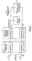
- the radio signals, s i GPS, are received by the N sensors Ci of an antenna array.
- Frequency transposition is performed by methods known to those skilled in the art, such as that described in patent FR 2,742,612 of the applicant for example. These signals thus brought to an intermediate frequency are optionally filtered.
- the set of treatments is performed by an analog process known to those skilled in the art.
- the filtered signals are then digitized using an ADC, 2, (digital analog converter), which works at a sampling frequency Fe chosen to comply with Shannon's theorem.
- ADC digital analog converter
- the CAN generates digital samples which contain GPS information at a clock rate Fe and over the entire band of the wanted signal and which are applied to a calculation unit 3 and to a processing block 4.
- the calculation unit 3 identifies, on the basis of a CRPA type algorithm and implementing a power inversion calculation, the directions in which sources of interference are present. This unit 3 determines the different weighting coefficients W i to be applied to the digital samples.
- the weighting coefficients w i are applied at the input of the processing block 4 to the samples x i directly from the CAN 2, the block 4 being adapted to remove the sources of interference in the reconstituted samples, for example by combining the weighted samples .
- the algorithm for determining the weighting coefficients to be applied to the samples is particularly well suited to so-called “narrowband" signals, that is to say of the pure wave (CW continuous wave) or little frequency-spreading type, typically for reporting frequency width / center frequency very much lower than the unit.
- “narrowband” signals that is to say of the pure wave (CW continuous wave) or little frequency-spreading type, typically for reporting frequency width / center frequency very much lower than the unit.
- US-A-5,550,872 discloses a method for eliminating interference of signals received by a diversity receiver.
- EP-A-0 869 627 applies power inversion algorithms to eliminate interference in signals received by a N-array sensor. These patents are not suitable for GPS receivers.
- the object of the invention relates to a signal processing method for eliminating interference in a signal received by a network of N sensors, for example a satellite signal received by a GPS receiver.
- CRPA Controled Radiation Pattern Antenna
- the method and the device according to the invention are applied for example to eliminate interference in signals transmitted by a satellite and received by a GPS receiver, or by a spread spectrum positioning system or a navigation system and Spread spectrum communication.
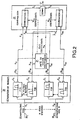
- the device comprises in a manner similar to FIG. 1, an array of N sensors Ci, a frequency transposition block and a CAN, not shown in FIG. 2 for the sake of simplification.
- N samples from the CAN 2 are applied to a device 20 adapted to perform a frequency division.
- the frequency division is performed using a set of K finite impulse response digital filters, for example FIR (Finite Impulse Response) digital filters.
- the device 20 is provided with N input channels 20 i corresponding to the N samples x i , i being an index designating a sample, and N * K output channels 20 ik , with k the index corresponding to the filter used.
- a sample x i is applied to the K filters G k so as to obtain K digital signals designated x ik , corresponding to K bands smaller than the initial band of the signal.
- each and / or of the set of K filters G 1 to G K are chosen so that the sum of the frequency bands thus obtained for each sample x ik reconstitutes completely or as completely as possible the overall useful band .
- Each sample has a useful band of 20 MHz corresponding to the useful band of the GPS signal received on the sensor Ci.
- the band separation process is performed, preferably digitally, which allows precise adjustment of the coefficients of the different filters in order to reconstruct the overall band without distortion.
- the samples x ik thus obtained are applied on the one hand to a computing unit 21 and on the other hand to a processing block 22.
- the calculation unit 21 is programmed to perform a CRPA-type power inversion processing and to compute the dedicated bandwidth weighting coefficients w ik for the N * K samples.
- the method is in possession of K sets of weighting coefficients (N * K coefficients) to be applied to the various samples x ik, for example at the input of the processing block 22.
- the weighting coefficients thus obtained are better suited for eliminating K potential interference bands.
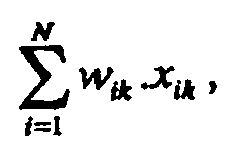
- the processing block 22 is adapted to combine the weighted samples, w ik .x ik .
- the different calculations are carried out using appropriate processing algorithms, the components used being of FPGA or ASIC type.
- this embodiment makes it possible to overcome the "narrow band" limitation of the adaptive power inversion methods of CRPA type commonly used.
- the noise level is brought back to the treatment so, with equivalent filtering treatment, the sensitivity of the process is increased.
- FIG. 3 describes a second exemplary embodiment of the invention in which the homologous elements taken from FIG. same references. This embodiment is particularly well suited in the case of mobile interference or mobile carriers.
- the N * K weighting coefficients obtained by the power inversion calculation are applied to a dynamic filtering step, for example by using a Kalman type filter, 30.
- the filter made with the aid of a suitable device in particular has the function of separating the directional components of the N * K coefficients (dynamic dynamics important or related to the dynamics of the disrupter) of the bias related to the reception lines (continuous components on a distant horizon).
- the dynamics of the disrupter is for example spectral, scrambling type scrambler, or geographic jammer type embedded, interfering jammer or time-type pulsed jammer.
- the Kalman filter By adapting the Kalman filter to the different dynamics, it is possible to reduce on the one hand the dynamic problems related to the monitoring of the interference during a movement, for example a strong operational constraint, while correcting the receiver bias. , such as RF faults in particular: phase pairing, amplitude, etc., which are limiting for the elimination performance.
- the filtered coefficients are then sent to the processing block 22 to effect the combination of the different weighted samples, this operation being carried out by frequency band, as described with reference to FIG. 2.
- the overall signal after treatment is then reconstituted by summation, for example, before being used according to the methods known in the prior art as a signal from a conventional CRPA.
- the method applies in the field of inertial / GPS hybridization and also to any field for separating the dynamics included in the weighting coefficients.
- the method also applies to all the signals of a spread spectrum positioning system, such as GPS, the system GLONASS (Global Orbiting Navigation Satellite System), Galileo or any spread spectrum communication and nagivation system.
- a spread spectrum positioning system such as GPS, the system GLONASS (Global Orbiting Navigation Satellite System), Galileo or any spread spectrum communication and nagivation system.
Description
L'invention concerne un procédé et un dispositif pour traiter, éliminer, les interférences présentes dans un ou plusieurs signaux reçus par un réseau de N capteurs.The invention relates to a method and a device for processing, eliminating, the interference present in one or more signals received by a network of N sensors.
Elle s'applique pour l'élimination d'interférences volontaires ou involontaires, occupant tout ou partie du spectre du signal satellite reçu par des récepteurs GPS (Global Positioning system).It applies to the elimination of intentional or unintentional interference, occupying all or part of the spectrum of the satellite signal received by GPS receivers (Global Positioning System).
Elle trouve son application pour améliorer les processus de traitement des interférences dans différents traitements de signal.It finds its application to improve the processing of interference in different signal processing.
Elle peut aussi être utilisée pour éliminer, d'un signal reçu par des récepteurs standards, des interférences volontaires ou involontaires.It can also be used to eliminate, from a signal received by standard receivers, voluntary or involuntary interferences.
Les systèmes permettant d'effectuer des traitements anti-interférences sur la base des réseaux d'antennes, utilisent à ce jour des méthodes prenant en compte, comme données d'entrée, la totalité de la bande du signal GPS reçu.Systems for performing anti-interference processing on the basis of antenna arrays currently use methods that take into account, as input data, the entire band of the received GPS signal.
La plupart de ces méthodes consistent à former une antenne apparente en combinant de manière pondérée les signaux issus de capteurs élémentaires. Il s'agit en fait d'utiliser un réseau de capteurs séparés dans l'espace et, par une combinaison « constructive » ou « destructive », d'atténuer très fortement le signal dans toutes les directions identifiées comme étant occupées par une ou plusieurs interférences. Typiquement, il s'agit de principes classiques de CRPA (antenne à diagramme de rayonnement contrôlé ou en abrégé anglo-saxon Controled Radiation Pattern Antenna) mettant en oeuvre des algorithmes d'inversion de puissance particulièrement bien adaptés aux signaux utiles de bruit de niveau inférieur au bruit thermique, ce qui est le cas du signal GPS.Most of these methods consist of forming an apparent antenna by weighting the signals from elementary sensors. It is in fact to use a network of sensors separated in space and, by a combination "constructive" or "destructive", to strongly attenuate the signal in all the directions identified as being occupied by one or more interference. Typically, these are conventional principles of CRPA (Controlled Radiation Pattern Antenna) using power inversion algorithms particularly well adapted to useful low-level noise signals. thermal noise, which is the case of the GPS signal.
L'algorithme de CRPA utilise, pour déterminer les coefficients de combinaison précités, le principe décrit ci-après en relation avec la figure 1.The CRPA algorithm uses, in order to determine the aforementioned combination coefficients, the principle described below in relation with FIG.
Les signaux analogiques radioélectriques, si , GPS sont reçus par les N capteurs Ci d'un réseau d'antennes. Ces signaux si ont un spectre constitué d'une bande de 20 MHz centrée sur la fréquence L1 = 1.575 GHz (fréquence porteuse), respectivement la fréquence L2 = 1.273 GHz, ces deux fréquences porteuses étant connues du domaine GPS. Ils sont transmis à un ensemble 1 de circuits de transposition, pour être transposés à une fréquence intermédiaire Fi plus faible que la fréquence porteuse L1 (respectivement L2). La transposition de fréquences est effectuée par des méthodes connues de l'Homme du métier, telle que celle décrite dans le brevet FR 2.742.612 du demandeur par exemple. Ces signaux ainsi amenés à une fréquence intermédiaire sont éventuellement filtrés. L'ensemble des traitements est réalisé par un processus analogique connu de l'Homme du métier. Les signaux filtrés sont ensuite numérisés à l'aide d'un CAN, 2, (convertisseur analogique numérique), qui travaille à une fréquence d'échantillonnage Fe choisie pour respecter le théorème de Shannon. Le CAN génère des échantillons numériques qui contiennent des informations GPS à une fréquence de cadence Fe et sur la totalité de la bande du signal utile et qui sont appliqués à une unité de calcul 3 et à un bloc de traitement 4.The radio signals, s i , GPS, are received by the N sensors Ci of an antenna array. These signals s i have a spectrum consisting of a 20 MHz band centered on the frequency L 1 = 1.575 GHz (carrier frequency), respectively the frequency L 2 = 1.273 GHz, these two carrier frequencies being known from the GPS domain. They are transmitted to a
L'unité de calcul 3 identifie, sur la base d'un algorithme de type CRPA et en mettant en oeuvre un calcul d'inversion de puissance, les directions dans lesquelles sont présentes des sources d'interférences. Cette unité 3 détermine les différents coefficients de pondération Wi à appliquer aux échantillons numériques.The calculation unit 3 identifies, on the basis of a CRPA type algorithm and implementing a power inversion calculation, the directions in which sources of interference are present. This unit 3 determines the different weighting coefficients W i to be applied to the digital samples.
Les coefficients de pondération wi sont appliqués en entrée du bloc de traitement 4 aux échantillons xi provenant directement du CAN 2, le bloc 4 étant adapté à faire disparaître les sources d'interférences dans les échantillons reconstitués, par exemple par combinaison des échantillons pondérés.The weighting coefficients w i are applied at the input of the
L'algorithme de détermination des coefficients de pondération à appliquer aux échantillons, est particulièrement bien adapté à des signaux dits « bande étroite », c'est-à-dire de type Onde pure (CW continuous Wave) ou peu étalés en fréquence, typiquement pour des rapports largeurfréquentielle/fréquencecentrale très très inférieurs à l'unité. Lorsqu'une interférence intervient sur une bande fréquentielle importante, par exemple sur la totalité des 20 MHz dans le cas du GPS code P présent sur la bande L2, ou encore du code C/A présent sur la bande L1, les interférences sont moins bien éliminées par l'algorithme d'inversion de puissance ou plus vraisemblablement le nombre de degrés de liberté disponibles, donc le nombre d'interférences auxquelles le récepteur est résistant s'en voit diminué.The algorithm for determining the weighting coefficients to be applied to the samples is particularly well suited to so-called "narrowband" signals, that is to say of the pure wave (CW continuous wave) or little frequency-spreading type, typically for reporting frequency width / center frequency very much lower than the unit. When interference occurs over a large frequency band, for example over all 20 MHz in the case of the GPS code P present on the L 2 band, or the C / A code present on the L 1 band, the interferences are less well eliminated by the inversion algorithm or more likely the number of degrees of freedom available, so the number of interference to which the receiver is resistant is reduced.
D'autre part, dans le cas de porteurs mobiles (récepteurs de type GPS ou stations comportant des récepteurs GPS) et/ou pour des interférences mobiles dans l'espace, l'estimation de la puissance et la combinaison à effectuer est plus bruitée. Elle est donc moins précise instantanément, et il peut en résulter des sauts de phase dans le signal GPS reconstitué qui vont sensiblement perturber son fonctionnement nominal. Une des méthodes mises en oeuvre pour remédier à ce problème, consiste à intégrer dans l'algorithme de traitement, un stratagème de lissage, par exemple par addition de bruit fictif, afin de réduire le bruit résultant sur les coefficients de pondération et donc sur la phase du signal résultant. De tels artifices peuvent, toutefois, détériorer la sensibilité du système anti-perturbateurs, c'est-à-dire le niveau d'interférence minimal à partir duquel l'algorithme d'inversion de puissance va « voir » et traiter l'interférence. En ajoutant du bruit fictif, le plancher global de signal au-dessus duquel l'algorithme « verra » l'interférence est remonté et les « petites » interférences ne sont pas vues.On the other hand, in the case of mobile carriers (GPS type receivers or stations with GPS receivers) and / or for mobile interferences in space, the estimation of the power and the combination to be performed is more noisy. It is therefore less precise instantaneously, and it may result in phase jumps in the reconstituted GPS signal that will substantially disrupt its nominal operation. One of the methods implemented to remedy this problem consists in integrating into the processing algorithm, a smoothing scheme, for example by adding fictitious noise, in order to reduce the noise resulting on the weighting coefficients and therefore on the phase of the resulting signal. Such artifices may, however, deteriorate the sensitivity of the anti-interference system, i.e., the minimum interference level from which the power inversion algorithm will "see" and process the interference. By adding fictitious noise, the overall signal floor above which the algorithm will "see" the interference is reassembled and the "small" interferences are not seen.
Le document US-A-5 550 872 décrit un procédé pour éliminer les intérférences des signaux reçus par un récepteur en diversité.US-A-5,550,872 discloses a method for eliminating interference of signals received by a diversity receiver.
Le document EP-A-0 869 627 applique des algorithmes d'inversion de puissance pour éliminer des interférences dans des signaux reçus par un réseau de N capteur. Ces brevets ne sont pas adaptés aux récepteurs GPS.EP-A-0 869 627 applies power inversion algorithms to eliminate interference in signals received by a N-array sensor. These patents are not suitable for GPS receivers.
L'objet de l'invention concerne un procédé de traitement de signal permettant d'éliminer des interférences dans un signal reçu par un réseau de N capteurs, par exemple un signal satellite reçu par un récepteur GPS.The object of the invention relates to a signal processing method for eliminating interference in a signal received by a network of N sensors, for example a satellite signal received by a GPS receiver.
L'objet de l'invention concerne un procédé pour éliminer les interférences occupant une partie au moins du spectre d'un ou de plusieurs signaux reçus par un réseau de N capteurs comportant au moins des étapes où :
- on découpe chaque échantillon x1 de signaux en K bandes de fréquence,
- on pondére les échantillons xik obtenus par découpage, avec des coefficients de pondération wik déterminés par traitement d'inversion de puissance,
- on combine par indice k de bande de fréquence donné les différents échantillons pondérés wik.xik afin d'obtenir des signaux sk correspondant à

- each sample x 1 of signals is cut into K frequency bands,
- weighting the samples x ik obtained by cutting, with weighting coefficients w ik determined by reverse power processing,
- the weighted index k of the given frequency band is combined with the different weighted samples w ik .x ik in order to obtain signals s k corresponding to
Le procédé peut comporter au moins les étapes suivantes :
- numériser les signaux si reçus par les capteurs en N échantillons numériques xi,
- transmettre les xi échantillons numériques à K filtres Gk afin de découper chaque échantillon xi en K bandes de fréquence,
- appliquer les xik échantillons obtenus par découpage à :
- une unité de calcul adaptée à déterminer les coefficients de pondération wik, par traitement d'inversion de puissance,
- un bloc de traitement adapté à :
- combiner pour un indice k de filtre donné les différents échantillons pondérés wik. xik, pour obtenir un signal sk correspondant à
- combiner les signaux sk afin d'obtenir un signal S' exempt en totalité ou en majorité d'interférences.
- combiner pour un indice k de filtre donné les différents échantillons pondérés wik. xik, pour obtenir un signal sk correspondant à
- digitizing the signals S i received by the sensors into N digital samples x i,
- transmit the x i digital samples to K filters G k in order to cut each sample x i into K frequency bands,
- apply the x ik samples obtained by cutting to:
- a calculation unit adapted to determine the weighting coefficients w ik , by power reversal processing,
- a processing block adapted to:
- to combine for a given index k of the given filter the different weighted samples w ik . x ik , to obtain a signal s k corresponding to
- combining the signals s k to obtain a signal S 'totally or mostly free of interference.
- to combine for a given index k of the given filter the different weighted samples w ik . x ik , to obtain a signal s k corresponding to
L'objet de l'invention concerne aussi un dispositif pour éliminer les interférences dans un ou plusieurs signaux si reçus par un réseau de N capteurs comportant au moins un ensemble de moyens adaptés à découper en fréquence chaque échantillon xi de signal en K bandes de fréquence, pondérer les échantillons xik obtenus par découpage, combiner par indice k de bande de fréquence donné les différents échantillons pondérés wik.xik afin d'obtenir des signaux sk correspondant à ![]()
![]()
Selon un mode de réalisation, le dispositif comporte au moins :
- une chaîne de réception de signaux comportant des circuits de transposition en fréquence de la fréquence du signal initial à une fréquence intermédiaire et un CAN pour convertir le signal S en N échantillons numérisés,
- un dispositif adapté pour découper chaque signal numérisé xi, en K bandes de fréquence afin de fournir N*K échantillons xik,
- une unité de calcul recevant les N*K échantillons et adaptée à déterminer des coefficients de pondération wik, par traitement d'inversion de puissance.
- un bloc de traitement recevant les coefficients de pondération wik et les échantillons xik, ledit bloc étant adapté à appliquer les coefficients de pondération aux différents échantillons, à réaliser la combinaison d'une part pour un indice k donné des Xik échantillons pondérés avec k variant de 1 à K et d'autre part des K signaux Sk avec k variant de 1 à K, afin d'obtenir un signal S'.
- a signal reception chain comprising frequency conversion circuits of the frequency of the initial signal at an intermediate frequency and an ADC for converting the signal S into N digitized samples,
- a device adapted to cut each digitized signal x i in K frequency bands to provide N * K samples x ik ,
- a calculation unit receiving the N * K samples and adapted to determine weighting coefficients w ik , by power reversal processing.
- a processing block receiving the weighting coefficients w ik and the samples x ik , said block being adapted to apply the weighting coefficients to the different samples, to perform the combination on the one hand for a given index k of the X ik samples weighted with k varying from 1 to K and, on the other hand, K signals S k with k varying from 1 to K, in order to obtain a signal S '.
Le procédé et le dispositif selon l'invention sont apliqués par exemple pour éliminer les interférences dans des signaux émis par un satellite et reçu par un récepteur GPS, ou encore par un système de positionnement à étalement de spectre ou encore un système de navigation et de communication à étalement de spectre.The method and the device according to the invention are applied for example to eliminate interference in signals transmitted by a satellite and received by a GPS receiver, or by a spread spectrum positioning system or a navigation system and Spread spectrum communication.
L'invention offre notamment les avantages suivants :
- elle permet de renforcer de manière très sensible les capacités de résistance aux perturbateurs (interférences volontaires ou involontaires),
- basée sur le principe du traitement « réseau » permettant de faire la suppression « spatiale », l'invention se libère des approximations « bandes étroites » classiquement utilisées,
- elle ramène pour le traitement adaptatif, moins de bruit dans la bande réduite, ce qui aura tendance à augmenter la sensibilité de l'algorithme utilisé,
- par adjonction d'un filtrage de Kalman,
- elle résorbe les défauts de traitement liés aux dynamiques des porteurs et des perturbateurs, et
- permet d'obtenir un processus adaptatif de correction des défauts susceptibles d'être introduit par la réalisation matérielle, évolution des capacités des composants en fonction de la thermique par exemple.
- it makes it possible to very significantly strengthen the resistance capabilities to the disturbers (voluntary or involuntary interferences),
- based on the principle of "network" processing allowing the "spatial" suppression, the invention is freed from the "narrow band" approximations conventionally used,
- it reduces for adaptive processing, less noise in the reduced band, which will tend to increase the sensitivity of the algorithm used,
- by adding a Kalman filter,
- it solves the processing defects related to the dynamics of carriers and disrupters, and
- allows to obtain an adaptive process of correction of the defects likely to be introduced by the material realization, evolution of the capacities of the components according to the thermal one for example.
D'autres caractéristiques et avantages de l'invention apparaîtront à la lecture de la description détaillée qui suit donnée en référence aux dessins annexés dans lesquels :
- la figure 1 représente un exemple de récepteur GPS selon l'art antérieur,
- la figure 2 schématise une première mise en oeuvre de l'invention, et
- la figure 3 représente une deuxième mise en oeuvre de l'invention intégrant un filtre de Kalman.
- FIG. 1 represents an example of a GPS receiver according to the prior art,
- FIG. 2 schematizes a first implementation of the invention, and
- FIG. 3 represents a second implementation of the invention integrating a Kalman filter.
Afin de mieux comprendre l'objet de l'invention, la description qui suit est donnée à titre d'exemple illustratif et nullement limitatif pour le traitement d'interférences dans des signaux reçus par des récepteurs GPS.In order to better understand the subject of the invention, the following description is given by way of illustrative and non-limiting example for the treatment of interference in signals received by GPS receivers.
Le dispositif comporte de façon similaire à la figure 1, un réseau de N capteurs Ci, un bloc de transposition de fréquence et un CAN, non représentés sur la figure 2 pour des raisons de simplification.The device comprises in a manner similar to FIG. 1, an array of N sensors Ci, a frequency transposition block and a CAN, not shown in FIG. 2 for the sake of simplification.
Les N échantillons issus du CAN 2 (figure 1) sont appliqués à un dispositif 20 adapté à réaliser un découpage en fréquence. Le découpage en fréquence est effectué en utilisant un ensemble de K filtres numériques à réponse impulsionnelle finie, par exemple des filtres numériques FIR (Finite Impulse Response). Le dispositif 20 est pourvu de N voies d'entrée 20i correspondant aux N échantillons xi, i étant un indice désignant un échantillon, et N*K voies de sortie 20ik, avec k l'indice correspondant au filtre utilisé. Un échantillon xi est appliqué aux K filtres Gk de manière à obtenir K signaux numériques désignés par xik, correspondant à K bandes plus restreintes que la bande initiale du signal.N samples from the CAN 2 (Figure 1) are applied to a
Les caractéristiques de chacun et/ou de l'ensemble des K filtres G1 à GK sont choisies pour que la somme des bandes de fréquence ainsi obtenues pour chaque échantillon xik, reconstitue de manière complète ou la plus complète possible la bande utile globale. Chaque échantillon a une bande utile de 20 MHz correspondant à la bande utile du signal GPS reçu sur le capteur Ci.The characteristics of each and / or of the set of K filters G 1 to G K are chosen so that the sum of the frequency bands thus obtained for each sample x ik reconstitutes completely or as completely as possible the overall useful band . Each sample has a useful band of 20 MHz corresponding to the useful band of the GPS signal received on the sensor Ci.
Le processus de séparation de bandes est réalisé, de préférence de manière numérique, ce qui permet un ajustement précis des coefficients des différents filtres afin de reconstituer sans distorsion la bande globale.The band separation process is performed, preferably digitally, which allows precise adjustment of the coefficients of the different filters in order to reconstruct the overall band without distortion.
Les échantillons xik ainsi obtenus sont appliqués d'une part à une unité de calcul 21 et d'autre part à un bloc 22 de traitement.The samples x ik thus obtained are applied on the one hand to a
L'unité de calcul 21 est programmée pour effectuer un traitement d'inversion de puissance de type CRPA et pour calculer les coefficients de pondération wik dédiés, bande par bande pour les N*K échantillons. A l'issu de ce calcul, le procédé est en possession de K jeux de coefficients de pondération (N*K coefficients), à appliquer aux différents échantillons xik par exemple en entrée du bloc de traitement 22. Les coefficients de pondération ainsi obtenus sont mieux adaptés à l'élimination des K bandes d'interférences potentielles.The
Le bloc de traitement 22 est adapté pour combiner les échantillons pondérés, wik.xik. L'étape de combinaison est réalisée par exemple en combinant dans un premier temps, pour un indice k de filtre donné, les différents échantillons pondérés en faisant varier l'indice i de 1 à N, pour obtenir plusieurs signaux sk correspondant à 
![]()
![]()
Avantageusement, ce mode de mise en oeuvre permet de dépasser la limitation « bande étroite » des méthodes adaptatives d'inversion de puissance de type CRPA habituellement utilisées. D'autre part, en travaillant sur des bandes plus étroites que la bande du signal initial, le niveau de bruit est ramené au traitement donc, à traitement de filtrage équivalent, la sensibilité du procédé est augmentée.Advantageously, this embodiment makes it possible to overcome the "narrow band" limitation of the adaptive power inversion methods of CRPA type commonly used. On the other hand, by working on bands narrower than the band of the initial signal, the noise level is brought back to the treatment so, with equivalent filtering treatment, the sensitivity of the process is increased.
La figure 3 décrit un deuxième exemple de réalisation de l'invention où les éléments homologues repris de la figure 2 portent les mêmes références. Ce mode de réalisation est particulièrement bien adapté dans le cas d'interférences mobiles ou de porteurs mobiles.FIG. 3 describes a second exemplary embodiment of the invention in which the homologous elements taken from FIG. same references. This embodiment is particularly well suited in the case of mobile interference or mobile carriers.
Dans cet exemple les N*K coefficients de pondération obtenus par le calcul d'inversion de puissance sont appliqués à une étape de filtrage de dynamique, en utilisant par exemple un filtre de type Kalman, 30. Le filtre réalisé à l'aide d'un dispositif adapté, a notamment pour fonction de séparer les composantes directionnelles des N*K coefficients (à dynamique importante ou liée à la dynamique du perturbateur) des biais liés aux lignes de réception (composantes continues sur un horizon lointain).In this example, the N * K weighting coefficients obtained by the power inversion calculation are applied to a dynamic filtering step, for example by using a Kalman type filter, 30. The filter made with the aid of a suitable device, in particular has the function of separating the directional components of the N * K coefficients (dynamic dynamics important or related to the dynamics of the disrupter) of the bias related to the reception lines (continuous components on a distant horizon).
La dynamique du perturbateur est par exemple spectrale, de type brouilleur à balayage, ou encore géographique de type brouilleur embarqué, commutation de brouilleur ou encore temporel de type brouilleur pulsé.The dynamics of the disrupter is for example spectral, scrambling type scrambler, or geographic jammer type embedded, interfering jammer or time-type pulsed jammer.
En adaptant le filtre de Kalman aux différentes dynamiques , il est possible de résorber d'une part les problèmes de dynamique liés au suivi de l'interférence au cours d'un mouvement, par exemple une contrainte opérationnelle forte, tout en corrigeant les biais récepteur, tels que les défauts HF en particulier : l'appairage en phase, l'amplitude, etc, qui sont limitatifs pour la performance d'élimination.By adapting the Kalman filter to the different dynamics, it is possible to reduce on the one hand the dynamic problems related to the monitoring of the interference during a movement, for example a strong operational constraint, while correcting the receiver bias. , such as RF faults in particular: phase pairing, amplitude, etc., which are limiting for the elimination performance.
Classiquement dans un filtre de Kalman, l'adaptation se fait par le choix judicieux du « bruit de modèle », celui-ci étant généralement fixe et déterminé à la conception mais peut aussi être modifié en fonction de critère ne provenant pas des mesures trouvées.Classically in a Kalman filter, the adaptation is made by the judicious choice of the "model noise", this one being generally fixed and determined at the design but can also be modified according to criterion not coming from the found measurements.
Les coefficients filtrés sont ensuite envoyés vers le bloc de traitement 22 pour effectuer la combinaison des différents échantillons pondérés, cette opération étant réalisée par bande de fréquence, comme il a été décrit en relation avec la figure 2.The filtered coefficients are then sent to the
Le signal global après traitement est ensuite reconstitué par sommation, par exemple, avant d'être utilisé selon les méthodes connues de l'art antérieur comme un signal issu d'une CRPA classique.The overall signal after treatment is then reconstituted by summation, for example, before being used according to the methods known in the prior art as a signal from a conventional CRPA.
Sans sortir du cadre de l'invention, le procédé s'applique dans le domaine de l'hybridation Inertie/GPS et aussi à tout domaine permettant de séparer les dynamiques incluses dans les coefficients de pondération.Without departing from the scope of the invention, the method applies in the field of inertial / GPS hybridization and also to any field for separating the dynamics included in the weighting coefficients.
Le procédé s'applique aussi à tous les signaux d'un système de positionnement à étalement de spectre, tel que le GPS, le système GLONASS (Global Orbiting Navigation Satellite System), Galiléo ou encore de tout système de nagivation et de communication à étalement de spectre.The method also applies to all the signals of a spread spectrum positioning system, such as GPS, the system GLONASS (Global Orbiting Navigation Satellite System), Galileo or any spread spectrum communication and nagivation system.
Claims (9)
- Method to eliminate interference occupying at least one part of the spectrum of one or more signals received by an array of N sensors, where:• each sample xi of signals is subdivided into K frequency bands,• the samples xik obtained by subdivision are weighted with weighting coefficients wik determined by power inversion processing,• the different weighted samples wik.xik are combined by given frequency band index k to obtain signals sk corresponding tocharacterized in that a CRPA (Controlled Radiation Pattern Antenna) algorithm is used for the power inversion processing.

- Method according to Claim 1, characterized in that it comprises at least the following steps:• digitizing the signals Si received by the sensors into N digital samples xi,• transmitting the xi digital samples to K filters Gk in order to subdivide each sample xi into K frequency bands,• applying the xik samples obtained by subdivision to:• a computation unit (3) adapted to determining the weighting coefficients wik, determined by power inversion processing using a CRPA algorithm,• a processing block (4) adapted to:• combining for a given filter index k the different weighted samples wik.xik, sk corresponding to
 • combining the signals sk in order to obtain a signal S' that is totally or mostly free of interference.
 - Method according to Claim 2, characterized in that the subdivision step uses an FIR type filter.
- Method according to one of Claims 1 to 3, characterized in that it comprises a step for filtering the dynamic range of the coefficients coming from the computation unit.
- Device to eliminate interference in one or more signals si received by an array of N sensors comprising at least one set of means adapted to subdividing each sample xi of signals into K frequency bands, weighting the samples xik obtained by subdivision with weighting coefficients obtained by power inversion processing, combining the different weighted samples wik.xik by given frequency band index k in order to obtain signals sk corresponding to

- Device according to Claim 5, characterized in that it comprises at least:• one signal reception chain comprising circuits for the frequency transposition of the frequency of the initial signal to an intermediate frequency and an ADC to convert the signal S into N digitized samples,• a device (20) adapted to subdividing each digitized signal xi, into K frequency bands, in order to give N*K samples Xik,• a computation unit (21) receiving the N*K samples and suited to determining weighting coefficients wik, by power inversion processing,• a processing block (22) receiving the weighting coefficients wik and the samples xik, said block being suited to the application of the weighting coefficients to the different samples, carrying out the combination firstly for a given index k of the xik weighted samples with k varying from 1 to K and secondly the K signals sk with k varying from 1 to K, in order to obtain a signal S'.
- Device according to one of Claims 5 or 6, characterized in that the means for subdividing the samples into K frequency bands is formed by a set of K FIR type filters.
- Device according to one of Claims 5 to 7, characterized in that it comprises a device (30) to filter the dynamic range of at least one of the weighting coefficients such as a Kalman filter.
- Application of the method according to one of Claims 1 to 4 or of the device according to one of Claims 5 to 8, to eliminate the interference in the signals sent by a satellite and received by a GPS receiver or again by a spread-spectrum positioning system or again a spread-spectrum navigation and communications system.
Applications Claiming Priority (2)
| Application Number | Priority Date | Filing Date | Title |
|---|---|---|---|
| FR0016874A FR2818840B1 (en) | 2000-12-22 | 2000-12-22 | METHOD AND DEVICE FOR HANDLING INTERFERENCE IN SIGNALS RECEIVED BY A SENSOR NETWORK |
| FR0016874 | 2000-12-22 |
Publications (2)
| Publication Number | Publication Date |
|---|---|
| EP1246373A1 EP1246373A1 (en) | 2002-10-02 |
| EP1246373B1 true EP1246373B1 (en) | 2006-03-22 |
Family
ID=8858083
Family Applications (1)
| Application Number | Title | Priority Date | Filing Date |
|---|---|---|---|
| EP01403289A Expired - Lifetime EP1246373B1 (en) | 2000-12-22 | 2001-12-18 | Method and apparatus for processing interferences in signals received by an antenna array |
Country Status (5)
| Country | Link |
|---|---|
| US (1) | US20020122473A1 (en) |
| EP (1) | EP1246373B1 (en) |
| CA (1) | CA2365334A1 (en) |
| DE (1) | DE60118146T2 (en) |
| FR (1) | FR2818840B1 (en) |
Families Citing this family (4)
| Publication number | Priority date | Publication date | Assignee | Title |
|---|---|---|---|---|
| FR2857101B1 (en) * | 2003-07-01 | 2007-01-05 | Thales Sa | METHOD FOR REJECTING INTERFERENCES WHICH DISRUPT THE RECEPTION OF A TRANSMISSION SIGNAL AND DEVICE |
| FR2867619B1 (en) * | 2004-03-12 | 2006-06-23 | Thales Sa | FREQUENCY OFFSET DEVICE IN A PULSED LASER SOURCE OPTICAL PATH |
| US8952844B1 (en) * | 2011-12-23 | 2015-02-10 | Lockheed Martin Corporation | System and method for adaptively matching the frequency response of multiple channels |
| PL3741008T3 (en) * | 2018-01-21 | 2024-01-03 | Infinidome Ltd. | Phased-array anti-jamming device and method |
Family Cites Families (14)
| Publication number | Priority date | Publication date | Assignee | Title |
|---|---|---|---|---|
| FR2751497B1 (en) * | 1990-06-08 | 1999-04-09 | Thomson Trt Defense | METHOD AND DEVICE FOR REJECTING A DISTURBING SIGNAL, PARTICULARLY FOR REJECTING AN ELECTRONIC RADIOCOMMUNICATION INTERFERENCE SIGNAL SIGNAL |
| DE69423922T2 (en) * | 1993-01-27 | 2000-10-05 | Koninkl Philips Electronics Nv | Sound signal processing arrangement for deriving a central channel signal and audio-visual reproduction system with such a processing arrangement |
| US5481570A (en) * | 1993-10-20 | 1996-01-02 | At&T Corp. | Block radio and adaptive arrays for wireless systems |
| JP2655092B2 (en) * | 1994-08-11 | 1997-09-17 | 日本電気株式会社 | Code division multiplex receiver |
| US5550872A (en) * | 1994-10-24 | 1996-08-27 | Motorola, Inc. | Method and apparatus for Fast Fourier Transform based maximal ratio combining |
| FR2739695B1 (en) * | 1995-10-06 | 1997-11-07 | Sextant Avionique | BROADBAND RECEIVER WITH DISTANCE MEASUREMENT BY PSEUDO-RANDOM CODE SIGNALS |
| FR2739938B1 (en) * | 1995-10-17 | 1997-11-07 | Sextant Avionique | RECEIVER FOR DETERMINING A POSITION FROM SATELLITE ARRAYS |
| FR2741173B1 (en) * | 1995-11-10 | 1997-12-05 | Sextant Avionique | FAST MULTIPLIER TO MULTIPLY A DIGITAL SIGNAL BY A PERIODIC SIGNAL |
| FR2742612B1 (en) * | 1995-12-15 | 1998-02-06 | Sextant Avionique | METHOD AND CIRCUIT FOR RECEIVING POSITIONING SIGNALS BY SATELLITES WITH ELIMINATION OF MULTI-PATH ERRORS |
| US5955987A (en) * | 1997-01-28 | 1999-09-21 | Northrop Grumman Corporation | Hybrid radio frequency system with distributed anti-jam capabilities for navigation use |
| JP2980053B2 (en) * | 1997-03-28 | 1999-11-22 | 日本電気株式会社 | Interference wave canceller |
| EP0912023A1 (en) * | 1997-10-27 | 1999-04-28 | Alcatel | Demodulation and equalisation of multicarrier signals |
| EP0975100A1 (en) * | 1998-07-23 | 2000-01-26 | Siemens Aktiengesellschaft | Receiver and method of recovering data from radio signals |
| FR2783929B1 (en) * | 1998-09-25 | 2000-12-08 | Sextant Avionique | PROCESS AND DEVICE FOR PROCESSING IN RECEPTION OF A GPS SATELLITE L2 SIGNAL |
-
2000
- 2000-12-22 FR FR0016874A patent/FR2818840B1/en not_active Expired - Fee Related
-
2001
- 2001-12-18 DE DE60118146T patent/DE60118146T2/en not_active Expired - Fee Related
- 2001-12-18 EP EP01403289A patent/EP1246373B1/en not_active Expired - Lifetime
- 2001-12-21 CA CA002365334A patent/CA2365334A1/en not_active Abandoned
- 2001-12-21 US US10/023,943 patent/US20020122473A1/en not_active Abandoned
Also Published As
| Publication number | Publication date |
|---|---|
| DE60118146T2 (en) | 2007-03-15 |
| CA2365334A1 (en) | 2002-06-22 |
| FR2818840A1 (en) | 2002-06-28 |
| FR2818840B1 (en) | 2004-06-04 |
| DE60118146D1 (en) | 2006-05-11 |
| EP1246373A1 (en) | 2002-10-02 |
| US20020122473A1 (en) | 2002-09-05 |
Similar Documents
| Publication | Publication Date | Title |
|---|---|---|
| EP0803991B1 (en) | Method for optimising radio communication between a base station and a mobile | |
| EP2018709B1 (en) | Method and device to combat interferences in a telecommunication system | |
| EP0858181A1 (en) | Method for diversity equalisation in a radio receiver having a predetermined number of receiving channels and corresponding receiver | |
| EP2579063B1 (en) | Method and system for locating interference by frequency sub-band | |
| EP0665665A1 (en) | Method and device enabling a modem to synchronize on a transmitter of digital data via a radio channel in the presence of interferences | |
| EP3188426B1 (en) | Method for controlling adaptive interference in a multi-channel receiver | |
| EP3343784B1 (en) | Method to prevent interference by spatial filtering or spatio-temporal filtering in a multi-channel receiver | |
| FR2814011A1 (en) | OPTIMAL ESTIMATION METHOD OF A PROPAGATION CHANNEL BASED ONLY ON PILOT SYMBOLS AND CORRESPONDING ESTIMATOR | |
| EP2523020A1 (en) | Method and system for locating interferences affecting a satellite radio-navigation signal | |
| EP0036794A1 (en) | Acoustic imaging system | |
| EP1185004A1 (en) | Joint angle of arrival and channel estimation method | |
| EP0991952B1 (en) | Radiogoniometry method and device co-operating in transmission | |
| EP2908155B1 (en) | Method for anti-jamming processing of a radio signal, related module and computer program | |
| EP1246373B1 (en) | Method and apparatus for processing interferences in signals received by an antenna array | |
| EP0778678B1 (en) | Differential receiver for direct sequence spread spectrum signals | |
| EP3254380B1 (en) | Method and system for suppressing a parasite signal received by a satellite payload | |
| EP2790035B1 (en) | Method and device for compressing a broadband radionavigation signal, related method and device for calculating the correlation function of the spreading code of said compressed signal | |
| EP3835811B1 (en) | Method for uncoupling of signals in transmitting/receiving systems | |
| EP1265374A2 (en) | Method and apparatus for signal processing in a spread spectrum radio communications receiver | |
| FR3116401A1 (en) | Method for processing a GNSS signal in order to attenuate at least one interference signal | |
| FR3127587A1 (en) | PROCEDURE FOR CALIBRATION OF A MULTI-CHANNEL RADIO RECEIVER | |
| EP2558881B1 (en) | Path-forming adaptive processing for active sonar | |
| FR3067186A1 (en) | METHOD FOR REMOVING MULTI-PATH SIGNALS FOR FREQUENCY MODULATED RADIO SIGNAL RECEIVER | |
| FR2965687A1 (en) | NOISE LIMITATION FOR TRANSMISSION IN A MULTI-CHANNEL CHANNEL |
Legal Events
| Date | Code | Title | Description |
|---|---|---|---|
| PUAI | Public reference made under article 153(3) epc to a published international application that has entered the european phase |
Free format text: ORIGINAL CODE: 0009012 |
|
| AK | Designated contracting states |
Kind code of ref document: A1 Designated state(s): AT BE CH CY DE DK ES FI FR GB GR IE IT LI LU MC NL PT SE TR |
|
| AX | Request for extension of the european patent |
Free format text: AL;LT;LV;MK;RO;SI |
|
| 17P | Request for examination filed |
Effective date: 20030327 |
|
| AKX | Designation fees paid |
Designated state(s): DE GB IT |
|
| 17Q | First examination report despatched |
Effective date: 20030618 |
|
| GRAP | Despatch of communication of intention to grant a patent |
Free format text: ORIGINAL CODE: EPIDOSNIGR1 |
|
| RAP1 | Party data changed (applicant data changed or rights of an application transferred) |
Owner name: THALES |
|
| GRAS | Grant fee paid |
Free format text: ORIGINAL CODE: EPIDOSNIGR3 |
|
| GRAA | (expected) grant |
Free format text: ORIGINAL CODE: 0009210 |
|
| AK | Designated contracting states |
Kind code of ref document: B1 Designated state(s): DE GB IT |
|
| REG | Reference to a national code |
Ref country code: GB Ref legal event code: FG4D Free format text: NOT ENGLISH |
|
| REF | Corresponds to: |
Ref document number: 60118146 Country of ref document: DE Date of ref document: 20060511 Kind code of ref document: P |
|
| GBT | Gb: translation of ep patent filed (gb section 77(6)(a)/1977) |
Effective date: 20060705 |
|
| PLBE | No opposition filed within time limit |
Free format text: ORIGINAL CODE: 0009261 |
|
| STAA | Information on the status of an ep patent application or granted ep patent |
Free format text: STATUS: NO OPPOSITION FILED WITHIN TIME LIMIT |
|
| 26N | No opposition filed |
Effective date: 20061227 |
|
| PG25 | Lapsed in a contracting state [announced via postgrant information from national office to epo] |
Ref country code: DE Free format text: LAPSE BECAUSE OF NON-PAYMENT OF DUE FEES Effective date: 20070703 |
|
| PGFP | Annual fee paid to national office [announced via postgrant information from national office to epo] |
Ref country code: IT Payment date: 20071221 Year of fee payment: 7 |
|
| PGFP | Annual fee paid to national office [announced via postgrant information from national office to epo] |
Ref country code: GB Payment date: 20121212 Year of fee payment: 12 |
|
| PG25 | Lapsed in a contracting state [announced via postgrant information from national office to epo] |
Ref country code: IT Free format text: LAPSE BECAUSE OF NON-PAYMENT OF DUE FEES Effective date: 20081218 |
|
| GBPC | Gb: european patent ceased through non-payment of renewal fee |
Effective date: 20131218 |
|
| PG25 | Lapsed in a contracting state [announced via postgrant information from national office to epo] |
Ref country code: GB Free format text: LAPSE BECAUSE OF NON-PAYMENT OF DUE FEES Effective date: 20131218 |