Field of the Invention
The present invention relates to an operation method for
a secondary battery that is repeatedly charged and discharged
for use and a secondary battery device.
Description of the Prior Art
For example, a secondary battery device mounted on an
electric vehicle provides energy for the vehicle to travel
by charging a secondary battery with a charger to a
predetermined charge end voltage and then discharging the
battery as required. Besides, in order to keep a temperature
of the secondary battery within a certain range in an
environment of low or high temperature, a temperature
controller having a cooling fan or heater is typically provided
in the secondary battery device.
Charge control by the charger in such a secondary battery
device is carried out in the following manner. That is, in
the case of a lithium secondary battery, for example, constant
current charge is first conducted with a constant current,
constant voltage charge is then conducted for a predetermined
time with a charge end voltage of, for example, 4.2 V, and
thereby the secondary battery is charged to 100% of a quantity
of charged electricity.
By the way, for leveling the electric power demand, some
office buildings are equipped with a secondary battery device
for storing a midnight electric power, for example. This
secondary battery device comprises a secondary battery, a
charger for charging the secondary battery with the midnight
electric power, and an inverter for generating an alternating
current power in the daytime from a DC power stored in the
secondary battery.
Charge control by the charger in such a secondary battery
device for load-leveling is carried out in the following manner.
That is, in the case of a lithium secondary battery, for example,
when the time period of the midnight electric power comes round,
constant current charge is first conducted with a constant
current, and upon attaining a predetermined voltage, the charge
scheme is shifted to constant voltage charge, which is
conducted for a predetermined time.
Such a secondary battery has a disadvantage that raising
the charge end voltage to enhance a charging rate promotes
degradation of the battery, resulting in a reduced life thereof.
This problem has been pointed out in Japanese Patent Laid-Open
No. 11-4549, in which extension of the battery life is attempted
by stopping charge before the secondary battery is fully
charged to suppress the quantity of charged electricity.
While the battery life can be extended by suppressing
the quantity of charged electricity as described in the above
Japanese Patent Laid-Open No. 11-4549, however, the reduced
quantity of charged electricity poses another problem of a
reduced utilization factor of the secondary battery. Thus,
the secondary battery cannot be fully used; for example, a
driving range of the electric vehicle maybe reduced. Although
such a circumstance is preferable for a user placing prime
importance on the battery life, it is not preferable for a
user placing prime importance on the capacity rather than the
life thereof. Furthermore, in the case of the secondary
battery device for load-leveling, since the required capacity
of the secondary battery is predetermined in the design stage
depending on a maximum power consumption by load, if the
utilization factor of the secondary battery is reduced, the
number of secondary batteries provided has to be increased
accordingly, and therefore, the cost of equipment will be
increased.
The present invention is devised in view of the above
described circumstances, and a first object of this invention
is to provide an operation method for a secondary battery and
a secondary battery device that allow a user to decide which
is to be given a priority, the life of the secondary battery
or capacity thereof. In addition, a second object of this
invention is to provide an operation method for a secondary
battery and a secondary battery device that can provide an
extended life of the secondary battery and an enhanced
utilization factor thereof.
Summary of the Invention
According to a first aspect of this invention, in a charge
operation of a secondary battery, at least two operation modes
including first and second operation modes in which the
secondary battery is charged to predetermined charge end
voltages different from each other are established, and either
of the two operation modes can be selected according to a control
signal from the outside of the secondary battery. In an
operation mode with high charge end voltage, high battery
capacity is provided, so that it is suitable for a case where
a user wishes to travel a long distance by an electric vehicle,
for example. On the other hand, in an operation mode with
low charge end voltage, although the battery capacity is
reduced, the life of the battery is extended, so that the running
cost thereof is advantageously reduced. The user can select
either of the modes arbitrarily.
In the case of a secondary battery device for load-leveling
installed in an office building, for example, while power
consumption by load is high on weekdays due to the operation
of office automation appliances and an air conditioning system
in the building, the power consumption by load is low on a
holiday due to the significantly reduced rate of operation
thereof. In this way, in a significant number of cases, the
power consumption by load of the secondary battery device
varies in a predetermined pattern. In such a secondary battery
device, there should be no problem if the quantity of charged
electricity of the secondary battery is suppressed before the
load is reduced.
Thus, according to a second aspect of this invention,
a timer device switches the operation mode between the first
operation mode and the second operation mode that are different
in charge end voltage. By the timer device establishing the
first operation mode with high charge end voltage when the
power consumption by load is high and the second operation
mode with low charge end voltage when the power consumption
by load is low, degradation of the secondary battery can be
minimized while assuring a required quantity of electric power.
Alternatively, the first and second operation modes may
be switched to each other according to the battery temperature.
When the battery temperature is higher than a predetermined
value, the battery is charged in the second operation mode
with low charge end voltage. This is because when the battery
temperature is high, the impedance of the battery is reduced
and the quantity of charged electricity tends to increase,
and the battery tends to be readily degraded, and therefore,
it is desired that the life of the battery is extended by lowering
the charge end voltage. Here, the battery temperature may
be measured with a temperature sensor attached to a battery
case, or a temperature of the air surrounding the installed
battery may be measured and regarded as the battery
temperature.
Alternatively, the first and second operation modes may
be switched to each other according to a state of health (SOH)
of the battery. When the state of health of the battery is
equal to or higher than a predeternined value, the battery
is charged in the second operation mode with low charge end
voltage, and when the state of health is equal to or lower
than the predetermined value, the battery is charged in the
first operation mode with high charge end voltage. When the
state of health of the battery is high, the capacity of the
battery is high and the internal resistance thereof is low,
so that operation with low charge end voltage is possible,
and thus, degradation of the battery is hard to advance. When
the state of health of the battery is reduced, increasing the
charge end voltage enables an extended period of use of the
battery. Here, the state of health of the battery can be
determined based on a voltage drop value and the battery
temperature during discharge of the battery.
Alternatively, in the case of a sealed battery, since
as degradation of the battery advances, the pressure in the
battery is increased, the internal pressure of the battery
may be measured, and the modes of the battery may be switched
to each other according to the internal pressure. In this
case, if degradation of the battery does not advance, and the
internal pressure is low, degradation of the battery can be
suppressed by operation with low charge end voltage. When
the internal pressure is increased due to degradation of the
battery, increasing the charge end voltage enables an extended
period of use of the battery. Here, the internal pressure
of the battery can be measured with a pressure sensor arranged
in the battery, or a strain gage attached to a surface of the
battery case.
In the case where a battery temperature controlling device
for controlling the battery temperature and the sensor for
detecting the state of the battery are provided, and the battery
is charged in the first operation mode with high charge end
voltage, it is desired that the temperature of the secondary
battery during charge and discharge is higher than that in
the second operation mode. This is because the higher
temperature allows the stored energy to be released more
efficiently and a larger service capacity to be assured. When
a state of charge of the battery is high, it is desired that
the operating temperature of the battery is low. This is
because while the battery tends to readily be degraded when
the state of charge of the battery is high, lowering the
operating temperature enables the degradation to be suppressed.
In addition, when a discharge current of the battery equal
to or lower than a predetermined value is detected, it is desired
that the operating temperature of the battery is low. This
is because when the load current is low, a low operating
temperature is sufficient for operation, as well as can lead
to suppression of the degradation of the battery.
Brief Description of the Drawings
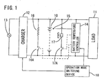
FIG. 1 is a block diagram showing a first embodiment of
this invention;
FIG. 2 is a graph showing variations in a voltage and
a current for a high capacity mode and a long life mode;
FIG. 3 is a block diagram showing a second embodiment
of this invention;
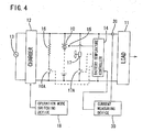
FIG. 4 is a block diagram showing a third embodiment of
this invention;
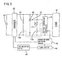
FIG. 5 is a block diagram showing a fourth embodiment
of this invention;
FIG. 6 is a time chart showing an operation pattern of
a battery according to the fourth embodiment of this invention;
FIG. 7 is a block diagram showing a fifth embodiment of
this invention;
FIG. 8 is a block diagram showing a sixth embodiment of
this invention;
FIG. 9 is a block diagram showing a seventh embodiment
of this invention;
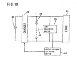
FIG. 10 is a block diagram showing an eighth embodiment
of this invention; and
FIG. 11 is a block diagram showing a ninth embodiment
of this invention.
Description of the Preferred Embodiments
<First Embodiment>
Now, a first embodiment of this invention applied to an
electric vehicle will be described with reference to FIGS.
1 and 2.
Reference numeral 10 denotes a lithium secondary battery,
which supplies a DC power to a load 11 composed of an inverter
and the like for driving an electric vehicle. A charger 12
is connected to the secondary battery 10, and thus the secondary
battery 10 can be charged with an alternating current power
supplied from a commercial power supply 13. An example of
a charge pattern is shown in FIG. 2, in which upon beginning
of charge, the battery is charged with a predetermined constant
current to a predetermined charge end voltage, and then
constant voltage charge with the charge end voltage is
conducted until a predetermined time T, which is the total
charge time, is reached. There are two operation modes of
a high capacity mode and a long life mode described later,
the charge end voltage for the high capacity mode being set
higher than that for the long life mode.
Reference numeral 14 denotes a temperature controller,
which has a function of controlling an operating temperature
of the secondary battery 10 based on a signal received from
a temperature sensor 15 provided in the secondary battery 10.
Specifically, the temperature controller has a heater 16 and
a cooling fan 17 attached to the secondary battery 10. When
the temperature of the secondary battery 10 detected by the
temperature sensor 15 is lower than a predetermined reference
temperature, the temperature controller closes a switch 16A
to energize the heater 16, thereby heating the secondary
battery 10, and when the temperature of the secondary battery
10 is higher than the predetermined reference temperature,
it closes a switch 17A to drive the cooling fan 17, thereby
cooling the secondary battery 10 with the outside air.
Reference numeral 18 denotes operation mode setting
means, which comprises a mode switch (not shown) provided on
an instrument panel of the electric vehicle, for example, and
can selectively switch between the high capacity mode and the
long life mode by manipulating the switch. The high capacity
mode corresponds to a "first operation mode" referred to herein,
and the long life mode corresponds to a "second operation mode"
referred to herein.
When the operation mode setting means 18 sets either of
the modes, a signal is transmitted to the charger 12 and the
temperature controller 14 according to the mode. For example,
in the high capacity mode, the charger 12 has a charge current
of 20A during the constant current charge and a charge end
voltage of 4.2 V, and in the long life mode, it has a charge
current of 10A during the constant current charge and a charge
end voltage 3.9 V. That is, the charge end voltage is higher
in the high capacity mode than in the long life mode, and the
charge current during the constant current charge is larger
in the high capacity mode than in the long life mode.
Furthermore, according to this embodiment, an average
operating temperature of the secondary battery 10 (during
charge and discharge) controlled by the temperature controller
14 is set to fall within the range of 35°C±20°C in the high
capacity mode, and is set to fall within the range of 15°C±20°C
in the long life mode.
According to this embodiment, when the high capacity mode
is set by the mode switch, the charge end voltage of the secondary
battery 10 during charge is set at the higher value of 4.2
V, and the average temperature thereof during operation is
set to fall within the range of 35°C±20°C, so that a fresh
battery is charged to a level of substantially 100% of a rated
capacity thereof. When the lithium secondary battery 10
having a capacity of 100Ah is used, the vehicle can travel
about 150 km at the maximum. On the other hand, when the mode
is switched to the long life mode by the mode switch, the charge
end voltage of the secondary battery 10 during charge is set
at the lower value of 3.9V, and the average temperature thereof
during operation is set to fall within the range of 15°C±20°C.
Accordingly, a fresh battery is charged to a level of
substantially 60% of a rated capacity thereof, and thus a
maximum driving range results in about 90 km, which is shorter
than that for the high capacity mode. However, since the
secondary battery 10 becomes less susceptible to degradation,
the life of the battery becomes longer.
Such switching between the operation modes may be
adequately conducted according to the utilization pattern of
the electric vehicle. For example, the secondary battery 10
may be used in the long life mode on weekdays when the vehicle
is used mainly in the neighborhood for shopping, commuting
or the like, and may be used in the high capacity mode on a
holiday when the vehicle is used for a long drive. In this
way, the life of the secondary battery 10 can be extended while
making the most of the power thereof as required.
In the above embodiment, the charge condition and the
operating temperature controlled by the
temperature
controller 14 for the respective operation modes were set as
shown in the table below.
| Operation Mode | Charge Current | Charge End Voltage | Total Charge Time | Operating Temperature |
| High capacity mode | 20A | 4.2 V | 8 hours | 35°C±20°C |
| Long life mode | 10A | 3.9 V | 8 hours | 15°C±20°C |
Then, assuming the following utilization of the electric
vehicle, the secondary battery 10 was repeatedly charged and
discharged. That is, the battery was discharged a number of
times corresponding to five days of a week supposing the
weekdays commuting (total driving range of about 40 km), and
was discharged a number of times corresponding to remaining
two days of a week supposing the holiday long drive (total
driving range of 80 km).
Here, in an operation example 1, charge and discharge
supposing weekdays were conducted in the long life mode in
which the average operating temperature of the secondary
battery 10 was 15°C, and charge and discharge supposing a
holiday were conducted in the high capacity mode in which the
average operating temperature of the secondary battery 10 was
35°C. Besides, in an operation example 2, except that the
average operating temperature of the secondary battery 10 was
set at 35°C for both the modes, charge and discharge were
repeated in the same manner as the operation example 1 with
the ratio of the long life mode to the high capacity mode being
5 to 2 (corresponding to an operation method as set forth in
claim 1 of this invention).
On the other hand, in a comparison operation example 1,
charge and discharge were always repeated only in the long
life mode in which the quantity of charged electricity of the
secondary battery 10 is 60% of a rated capacity for a fresh
battery, and in a comparison operation example 2, charge and
discharge were repeated only in the high capacity mode in which
the quantity of charged electricity of the secondary battery
10 is 100% of a rated capacity for a fresh battery.
Results of the above operations are shown in the table
below. Here, a "number of days of possible to drive" refers
to a total number of operating days before the vehicle can
no longer travel 40 km in a weekday or 80 km in a holiday.
| | Number of Days of Possible to Drive |
| Operation example 1 | 1197 days |
| Operation example 2 | 763 days |
| Comparison operation example 1 | 490 days |
| Comparison operation example 2 | 637 days |
As apparently seen from the above table, the number of
days of possible to drive in the operation examples 1 and 2
in this embodiment are 1.6 to 2 times larger than those in
the comparison operation examples 1 and 2 corresponding to
the conventional operation method for the secondary battery,
so that a long-life operation becomes possible. Here, the
number of days of possible to drive is smaller in the comparison
operation example 1 using only the long life mode than in the
comparison operation mode 2 using only the high capacity mode
because a fresh battery is charged to a quantity of charged
electricity enough for traveling only 90 km (60% of a rated
capacity thereof), and thus the driving range of 80 km in a
holiday cannot be covered if the battery is degraded.
<Second Embodiment>
FIG. 3 shows a second embodiment of this invention. A
difference between the second and first embodiments is that
a SOC measuring device 20 for measuring a state of charge of
the secondary battery 10 is provided, and the temperature
controller 14 is contrclled by the SOC measuring device 20.
The rest of the configuration is the same as the first embodiment,
so that a same portion as in the first embodiment is assigned
the same reference numeral and the description thereof is
omitted.
Here, the state of charge (SOC) of the secondary battery
10 indicates a remaining capacity at that time. A state in
which the battery is fully charged with the predetermined
charge end voltage intended for attaining the rated capacity
is defined as a SOC of 100%, and a state in which the battery
then discharges electricity corresponding to a half of the
rated capacity is defined as a SOC of 50%. The SOC is related
with a no-load terminal voltage (open terminal voltage) of
the secondary battery 10. Thus, the SOC measuring device 20
in this embodiment determines the SOC by obtaining the open
circuit voltage at that time relying on a table or arithmetic
equation of the open circuit voltage and the SOC created for
the same kind of secondary battery, for example. Then, if
the SOC is equal to or higher than 50%, for example, it outputs
a signal to the temperature controller 14 for keeping the
temperature of the secondary battery 10 relatively low
(15°C±2C°C, for example), and if the SOC is lower than 50%,
it outputs a signal to the temperature controller 14 for keeping
the temperature of the secondary battery 10 higher (35°C±20°C,
for example).
In this embodiment, as in the first embodiment, when the
high capacity mode is set by the mode switch in the operation
mode setting means 18, the charge end voltage of the secondary
battery 10 during charge is set at the higher value of 4.2
V, so that a fresh battery is charged to a level of substantially
100% of a rated capacity thereof. On the other hand, when
the mode is switched to the long life mode by the mode switch,
the charge end voltage of the secondary battery 10 during charge
is set at the lower value of 3.9 V, so that a fresh battery
is charged to a level of substantially 60% of a rated capacity
thereof, and thus a maximum driving range is shorter than that
for the high capacity mode. However, since the secondary
battery 10 becomes less susceptible to degradation, the life
of the battery becomes longer.
In addition, in either operation mode for charge, during
discharge, the temperature of the secondary battery 10 is kept
relatively low in the region of the SOC of 50% or higher where
the battery is susceptible to degradation. Accordingly,
degradation of the battery can be suppressed, and the life
thereof can be extended.
<Third Embodiment>
FIG. 4 shows a third embodiment of this invention. A
difference between the third and first embodiments is that
a current measuring device 30 for measuring a discharge current
from the secondary battery 10 is provided, and the temperature
controller 14 is controlled by the current measuring device
30. The rest of the configuration is the same as the first
embodiment, and a same portion as in the first embodiment is
assigned the same reference numeral so that the description
thereof is omitted.
The discharge current from the secondary battery 10 is
measured by a current sensor 31 provided in a discharge path
leading to the load 11, and if the discharge current is equal
to or lower than a predetermined value (20% of the rated current,
for example), a signal is output to the temperature controller
14 for keeping the temperature of the secondary battery 10
relatively low (15°C±20°C, for example), and if the discharge
current is higher than 20%, a signal is output to the temperature
controller 14 for keeping the temperature of the secondary
battery 10 higher (35°C±20°C, for example).
In this embodiment, as in the first embodiment, the high
capacity mode and the long life mode can be switched to one
another by the mode switch in the operation mode setting means
18. In addition, since the temperature of the secondary
battery 10 is kept relatively low if the current during
discharge is low, degradation of the battery can be suppressed.
Furthermore, since the temperature of the secondary battery
10 is kept relatively high if a large discharge current flows,
stored energy can be efficiently released in the form of
electric energy, and thus a certain service capacity can be
assured.
<Fourth Embodiment>
Now, a fourth embodiment of this invention applied to
a secondary battery for storing midnight electric power in
an office building will be described with reference to FIGS.
5 and 6.
Reference numeral 40 denotes a lithium secondary battery,
which supplies a DC power to a load 41 composed of an inverter
and the like connected to an electric power supply line in
the office building. A charger 42 is connected to the secondary
battery 40, and thus the secondary battery 40 can be charged
with the commercial power supply during the time period of
the midnight electric power according to a signal from a time
measuring device 44. The charge pattern is the same as that
shown in FIG. 2, for example, in which upon beginning of charge,
the battery is charged with a predetermined constant current
to a predetermined charge end voltage, and then constant
voltage charge with the charge end voltage is conducted until
a predetermined time T, which is the total charge time, is
reached. There are two operation modes of a high capacity
mode and a long life mode described later, the charge end voltage
for the high capacity mode being set higher than that for the
long life mode.
Reference numeral 14 denotes a temperature controller
having a function of controlling an operating temperature of
the secondary battery 40 based on a signal received from a
temperature sensor 15. Since it has the same configuration
as that in the first embodiment, a same portion as in the first
embodiment is assigned the same reference numeral and the
description thereof is omitted.
Reference numeral 45 denotes operationmode setting means,
which can transmit a signal to the charger 42 to switch the
operation mode thereof between the high capacity mode and the
long life mode. For example, in the high capacity mode, the
charger 42 has a charge current of 20A during the constant
current charge and a charge end voltage of 4.2 V, and in the
long life mode, it has a charge current of 10A during the constant
current charge and a charge end voltage 3.9 V. That is, the
charge end voltage is higher in the high capacity mode than
in the long life mode, and the charge current during the constant
current charge is larger in the high capacity mode than in
the long life mode. Furthermore, according to this embodiment,
the operation mode setting means 45 transmits a signal also
to the temperature controller 14, an average operating
temperature of the secondary battery 40 (during charge and
discharge) controlled by the temperature controller 14 is set
to fall within the range of 35°C±20°C in the high capacity
mode, and is set to fall within the range of 15°C±20°C in the
long life mode.
In addition, the timing of switching the operation mode
in the operation mode setting means 45 is controlled by a timer
device 46. The timer device 46 obtains time information from
the time measuring device 44 and follows a schedule previously
established and stored therein. For example, as shown in FIG.
6, the long life mode is adopted from Friday midnight to Sunday
evening, and the high capacity mode is adopted during the rest
time period (from Sunday midnight to Friday evening).
In the fourth embodiment, according to the schedule
established in the timer device 46, the charger 42 charges
the secondary battery 40 in the high capacity mode (with the
charge end voltage of 4.2 V) on weekdays, and is controlled
by the temperature controller 14 to attain the average
temperature falling within the range of 35°C±20°C during
operation. As a result, a fresh battery is charged to a level
of substantially 100% of a rated capacity thereof, and when
the lithium secondary battery 40 having a capacity of 100Ah
is used, electric power for about six hours during the daytime
on weekdays in a typical office building can be supplied.
Furthermore, the long life mode is automatically set
during the period from Friday midnight to Sunday evening. In
this case, the charge end voltage of the secondary battery
40 during charge is set at the lower value of 3.9 V, and the
average temperature thereof during operation is set to fall
within the range of 15°C±20°C. Accordingly, a fresh secondary
battery 40 is charged to a level of substantially 60% of a
rated capacity thereof, and thus degradation of the secondary
battery 40 is suppressed. In such a case, since the electric
power consumption of the office building is reduced on a holiday,
electric power for about six hours on a holiday can be supplied,
so that there is no problem practically.
In this embodiment, the charge condition and the operating
temperature controlled by the
temperature controller 14 for
the respective operation modes were set as shown in the table
below.
| Operation Mode | charge Current | Charge End Voltage | Total charge Time | Operating Temperature |
| High capacity mode | 20A | 4.2 V | 8 hours | 35°C±20°C |
| Long life mode | 10A | 3.9 V | 8 hours | 15°C±20°C |
Then, assuming the following electric power demand in
the office building, the secondary battery 40 was repeatedly
charged and discharged. That is, the battery discharged
electricity corresponding to the weekdays electric power
consumption (50Ah) a number of times corresponding to five
days in a week, and discharged electricity corresponding to
the holiday electric power consumption (25Ah) a number of times
corresponding to remaining two days in a week.
Here, in an operation example 3, the high capacity mode
was adopted on weekdays in which the quantity of charged
electricity of the secondary battery 40 is 100% of a rated
capacity thereof (100Ah) if the battery is fresh and the average
operating temperature thereof is 35°C, and the long life mode
was adopted on a holiday in which the quantity of charged
electricity of the secondary battery 40 is 60% of a rated
capacity thereof (60Ah) if the battery is fresh and the average
operating temperature thereof being 15°C.
On the other hand, in a comparison operation example 3,
charge and discharge were repeated only in the long life mode
(as above), and in a comparison operation example 4, charge
and discharge were repeated only in the high capacity mode
(as above).
Results of the above operations are shown in the table
below. Here, a "number of days of power available" refers
to a total number of days of power available before discharge
of 50Ah becomes impossible on a weekday, or discharge of 25Ah
becomes impossible on a holiday.
| | Number of Days of Power Available | Battery Capacity |
| | | Beginning of life | End of life |
| Operation example 3 | 1964 days | 100Ah (weekday) | 50Ah (weekday) |
| Comparison operation example 3 | 680 days | 60Ah | 50Ah |
| Comparison operation example 4 | 927 days | 100Ah | 50Ah |
As apparently seen from the above table, the number of
days of power available of the secondary battery 40 in the
operation example 3 is 2 or more times larger than that in
the comparison operation examples 3 and 4 corresponding to
the conventional operation method for the secondary battery,
so that a long-life operation becomes possible.
<Fifth Embodiment>
FIG. 7 shows a fifth embodiment of this invention. A
difference between the fifth and fourth embodiments is that
a SOC measuring device 50 is added thereto, and the temperature
controller 14 is controlled by the SOC measuring device 50
rather than the operation mode setting means 45. The rest
of the configuration is the same as the fourth embodiment,
so that a same portion as in the fourth embodiment is assigned
the same reference numeral and the description thereof is
omitted.
The SOC measuring device 50 determines the state of charge
based on the open circuit voltage of the secondary battery
40. If the SOC is equal to or higher than 50%, for example,
it outputs a signal to the temperature controller 14 for keeping
the temperature of the secondary battery 40 relatively low
(15°C±20°C, for example), and if the SOC is lower than 50%,
it outputs a signal to the temperature controller 14 for keeping
the temperature of the secondary battery 40 higher (35°C±20°C,
for example).
In this embodiment, as in the fourth embodiment, according
to the schedule established in the timer device 46, the charger
42 charges the secondary battery 40 in the high capacity mode
with the charge end voltage of 4.2 V on weekdays, so that a
fresh battery is charged to a level of substantially 100% of
a rated capacity thereof. Furthermore, the long life mode
is automatically set during the period from Friday midnight
to Sunday evening. In this case, the charge end voltage of
the secondary battery 40 during charge is set at the lower
value of 3.9 V, so that a fresh secondary battery 40 is charged
to a level of substantially 60% of a rated capacity thereof,
and thus degradation of the secondary battery 40 is suppressed.
In addition, in either operation mode for charge, during
discharge, the temperature of the secondary battery 40 is kept
relatively low (15°C±20°C) in the region of the state of charge
of 50% or higher where the battery is susceptible to degradation.
Accordingly, degradation of the battery can be suppressed,
and the life thereof can be extended further.
<Sixth Embodiment>
FIG. 8 shows a sixth embodiment of this invention. A
difference between the sixth and fifth embodiments is that
the SOC measuring device 50 is replaced with a current measuring
device 60 for measuring a discharge current from the secondary
battery 40, and the temperature controller 14 is controlled
by the current measuring device 60. The rest of the
configuration is the same as the fifth embodiment, and a same
portion as in the fifth embodiment is assigned the same
reference numeral so that the description thereof is omitted.
The discharge current from the secondary battery 40 is
measured by a current sensor 61 provided in a discharge path
leading to the load 41, and if the discharge current is equal
to or lower than a predetermined value (20% of the rated current,
for example) , a signal is output to the temperature controller
14 for keeping the temperature of the secondary battery 40
relatively low (15°C±20°C, for example), and if the discharge
current is higher than 20%, a signal is output to the temperature
controller 14 for keeping the temperature of the secondary
battery 40 higher (35°C±20°C, for example).
In this embodiment, as in the fifth embodiment, according
to the schedule established in the timer device 46, the charger
42 charges the secondary battery 40 in the high capacity mode
on weekdays, and in the long life mode from Friday midnight
to Sunday evening. In addition, since the temperature of the
secondary battery 40 is kept relatively low if the current
during discharge is low, degradation of the battery can be
suppressed. Furthermore, since the temperature of the
secondary battery 40 is kept relatively high if a large
discharge current flows, stored energy can be efficiently
released in the form of electric energy, and thus a certain
service capacity can be assured.
<Seventh Embodiment>
FIG. 9 shows a seventh embodiment of this invention.
Reference numeral 70 denotes a lithium secondary battery, which
supplies a DC power to a load 71 composed of an inverter and
the like for driving an electric vehicle. A charger 72 is
connected to the secondary battery 70, and thus the secondary
battery 70 can be charged with an alternating current power
supplied from a commercial power supply 73. The charge pattern
is arranged so that upon beginning of charge, the battery is
charged with a predetermined constant current to a
predetermined charge end voltage, and then constant voltage
charge with the charge end voltage is conducted until a
predetermined time T, which is the total charge time, is reached.
There are three operation modes differing from each other in
charge end voltage.
These operation modes are switched to each other according
to a signal received from operation mode setting means 74.
For example, in the high capacity mode corresponding to a first
operation mode, the charge end voltage is set at 4.2V, and
in the long life mode corresponding to a second operation mode,
the charge end voltage is set at 3.85 V. In addition, there
is provided an intermediate mode as a third operation mode,
in which the charge end voltage is set at 3.95 V, for example.
A
temperature sensor 75 is provided near the
secondary
battery 70, and by means of a signal from the sensor, the
temperature measuring device 76 measures the temperature of
the
secondary battery 70 and transmits a signal associated
with the temperature to the operation mode setting means 74.
The operation mode setting means 74 comprises a storage circuit
storing a table of the temperature and the modes associated
with each other as shown below, and determines the operation
mode according to the temperature.
| Temperature of Secondary Battery 70 | Operation Mode | Charge End Voltage |
| - 20°C - 10°C | Intermediate mode | 3.95 V |
| 10°C - 35°C | High capacity mode | 4.20 V |
| Higher than 35°C | Long life mode | 3.85 V |
In this embodiment, since charge is conducted in the high
capacity mode in a normal temperature range (10°C to 35°C),
a long drive is possible making the most of the capability
of the secondary battery 70. In the high temperature range
higher than 35°C, since the secondary battery 70 is charged
in the long life mode, degradation of the secondary battery
70 can be minimized. Beside, in the low temperature range
between -20°C and 10°C, since electrochemical activity of a
negative electrode is low, in the case of high utilization
factor, metallic lithium is readily deposited, so that
performance of the battery is readily degraded. However,
according to this embodiment, the battery is charged in the
intermediate mode with the charge end voltage of 3.95 V, so
that the utilization factor of the negative electrode can be
lowered, and degradation of the battery performance can be
minimized.
<Eighth Embodiment>
FIG. 10 shows an eighth embodiment of this invention.
Reference numeral 80 denotes a lithium secondary battery having
a capacity of 100Ah, for example, which supplies a DC power
to a load 81 composed of an inverter and the like for driving
an electric vehicle. A charger 82 is connected to the secondary
battery 80, and thus the secondary battery 80 can be charged
with an alternating current power supplied from a commercial
power supply 83. The charge pattern is arranged so that upon
beginning of charge, the battery is charged with a
predetermined constant current to a predetermined charge end
voltage, and then constant voltage charge with the charge end
voltage is conducted until a predetermined time T, which is
the total charge time, is reached. There are two operation
modes differing from each other in charge end voltage.
These operation modes are switched to each other according
to a signal received from operation mode setting means 84.
For example, in the high capacity mode corresponding to a first
operation mode, the charge end voltage is set at 4.2 V, and
in the long life mode corresponding to a second operation mode,
the charge end voltage is set at 3.9 V.
Reference numeral 85 denotes a SOH measuring device for
measuring a SOH (State of Health) of the
secondary battery
80. In general, as the state of health of the battery is reduced,
an internal resistance thereof is increased, so that the state
of health of the battery can be determined from a table of
a voltage drop value when the battery is discharged and a
temperature of the battery. An example of the table of the
state of health used in this embodiment is shown below, and
the table is stored in the storage in the
SOH measuring device
85. Here, the voltage drop value indicates a value (in the
unit V) attained after the
secondary battery 80 is discharged
at the level of 100A for three minutes, the SOH of 100% refers
to a state in which the
secondary battery 80 is a fresh one
and has a rated capacity thereof, and the SOH of 0% refers
to a state in which the
secondary battery 80 is degraded and
the service capacity thereof is reduced to the lowest level
required for the load.
| Temperature (°C) | SOH (%) |
| | 100 | 75 | 50 | 25 | 0 |
| - 10 | 0.91 | 1.43 | 1.88 | 2.29 | 2.73 |
| 0 | 0.46 | 0.72 | 0.97 | 1.21 | 1.38 |
| 10 | 0.27 | 0.39 | 0.58 | 0.74 | 0.81 |
| 20 | 0.22 | 0.33 | 0.47 | 0.59 | 0.66 |
| 30 | 0.17 | 0.26 | 0.35 | 0.43 | 0.51 |
The SOH measuring device 85 detects the temperature of'
the secondary battery 80 according to the signal from the
temperature sensor 85, detects the voltage drop value by
performing a discharge test on the secondary battery 80, and
determines the SOH according to the above table using these
values. Then, the SOH measuring device transmits a signal
to the operation mode setting means 84 to let the charger 82
operate in the long life mode until the SOH is reduced to 25%,
for example, and to let the charger 82 operate in the high
capacity mode when the SOH is equal to or lower than 25%.
According to this embodiment, since charge is conducted
in the long life mode when degradation of the secondary battery
80 is not advanced and the state of health falls within the
range from 100% to 25%, the advance of the degradation can
be suppressed to the utmost. Besides, in a state where the
state of health is equal to or lower than 25%, charge is conducted
in the high capacity mode, that maximizes the capability of
the battery which capacity is degrading.
Here, in the case where the operation mode of the charger
82 is switched based on the SOH as in this embodiment, the
temperature controller 14 may be provided as in the first
embodiment to keep the temperature of the secondary battery
80 low in the long life mode and high in the high capacity
mode. Besides, the SOC measuring device 2C may be provided
as in the second embodiment to keep the temperature of the
secondary battery 80 low when the SOC is high and high when
the SOC is low. Besides, the current measuring device 30 may
be provided as in the third embodiment to keep the operating
temperature low when the discharge current is low and high
when the discharge current is high.
<Ninth Embodiment>
FIG. 11 shows a ninth embodiment of this invention.
Reference numeral 90 denotes a lithium secondary battery, which
supplies a DC power to a load 91 composed of an inverter and
the like for driving an electric vehicle. A charger 92 is
connected to the secondary battery 90, and thus the secondary
battery 90 can be charged with an alternating current power
supplied from a commercial power supply 93. The charge pattern
is arranged so that upon beginning of charge, the battery is
charged with a predetermined constant current to a
predetermined charge end voltage, and then constant voltage
charge with the charge end voltage is conducted until a
predetermined time T, which is the total charge time, is reached.
There are two operation modes differing from each other in
charge end voltage.
These operation modes are switched to each other according
to a signal received from an operation mode setting means 94.
For example, in the high capacity mode corresponding to a first
operation mode, the charge end voltage is set at 4.2 V, and
in the long life mode corresponding to a second operation mode,
the charge end voltage is set at 3.9 V.
Reference numeral 95 denotes a pressure measuring device
for measuring an internal pressure of the secondary battery
90. In general, as the degradation of the battery is advanced,
the internal pressure thereof is increased, so that the degree
of the degradation can be found from the variation of the
internal pressure. While the internal pressure is detected
with a pressure sensor 96 attached to a battery case (not shown)
in this embodiment, it may also be detected with a strain gage
attached to a surface of the battery case. In this embodiment,
the internal pressure of the secondary battery 90 was 0.1 MPa
when the battery was fresh, 0.2 MPa when the state of health
was on the order of 50%, 0.25 MPa when the state of health
was 25%, and 0.3 MPa at the end of the life thereof.
The pressure measuring device 95 detects the internal
pressure of the secondary battery 90 according to a signal
from the pressure sensor 96, and transmits a signal to the
operation mode setting means 94 to let the charger 92 operate
in the long life mode until the pressure reaches 0.25 MPa,
for example, and to let the charger 92 operate in the high
capacity mode when the pressure is equal to or higher than
0.25 MPa.
According to this embodiment, since charge is conducted
in the long life mode when degradation of the secondary battery
90 is not advanced, the advance of the degradation can be
suppressed to the utmost. Besides, in a state where the
internal pressure is equal to or higher than 0.25 MPa (the
state of health is equal to or lower than 25%), charge is
conducted in the high capacity mode, that maximizes the
capability of the battery which capacity is degrading.
Here, also in the case where the operation mode of the
charger 92 is switched based on the internal pressure as in
this embodiment, the temperature controller 14 may be provided
as in the first embodiment. to keep the temperature of the
secondary battery 90 low in the long life mode and high in
the high capacity mode. Besides, the SOC measuring device
20 may be provided as in the second embodiment to keep the
temperature of the secondary battery 90 low when the SOC is
high and high when the SOC is low. Besides, the current
measuring device 30 may be provided as in the third embodiment
to keep the operating temperature low when the discharge
current is low and high when the discharge current is high.
The present invention is not limited to the embodiments
explained in the above description with reference to the
drawings, and the following embodiments are included in the
scope of this invention. And besides the following
embodiments, this invention can be modified without departing
from the spirit thereof.