Technical Field
The present invention relates to a data adaptation
apparatus and data adaptation method for adapting data
to the preferences of a user, and a recording medium that
includes a data adaptation apparatus. In particular, the
present invention relates to a data adaptation apparatus
for data including video, audio, and documents provided
via broadcasting or communication media such as digital
broadcasting or the Internet.
Background Art
In recent years, there has been an active trend of
digitalization of broadcasting, and fusion with
communications has also progressed. In the field of
communications, satellite digital broadcasting has
already been started, and it is expected that terrestrial
broadcasting will also be digitalized in the future. As
a result of digitalization of broadcast contents, data
broadcasting is also performed in addition to
conventional video and audio. Products that realize the
concept of storing television broadcasts on a hard disk
and playing them back later (TV Anytime), such as TiVo
(www.tivo.com)and ReplayTV(www.replaytv.com),are also
on the market in the United States. Also, in the
communications field, digital content distribution via
the Internet has begun with music, and the number of
Internet broadcasting stations that broadcast video is
also increasing. In addition, access to Internet content
has also been made possible for portable terminals through
wideband access networks and connection to the Internet.
Amid such dramatic changes in information
infrastructure, it is envisaged that henceforth it will
become possible for users to easily access enormous
information sources including video, audio, documents,
and the like. Due to the fusion and digitalization of
communications and broadcasting in this way, it has become
difficult for users to handle enormous information
sources without selectively transmitting and replaying
only information that accords with the preferences of
a user by using metadata that describes content.
As shown in "Adapting Multimedia Internet Content For
Universal Access" (IEEE Transactions on Multimedia, March
1999, pp.104-114), there have been proposed a description
scheme for distributing one content to various terminals
such as televisions and portable terminals, and accessing
rich content on the Internet from an HHC (Hand Held
Computer), PDA (Personal Digital Assistant), Smart Phone,
or the like, and a method for converting (performing data
adaptation of) Internet content according to the display
capability of a terminal (for example, by changing the
display size or number of display colors).
A conventional data adaptation apparatus will be
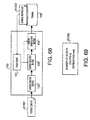
described below. FIG.68 shows a block diagram of a
conventional data adaptation apparatus. A conventional
data adaptation apparatus consists of a data adaptation
section 100, a policy engine 101, a content analysis
section 102, a content selection section 103, a content
manipulation section 104, and a terminal 105. Internet
content d1001 is input to the content analysis section
102. Terminal preferences d1002 that indicate terminal
105 performance information are stored in the terminal
105.
FIG.69 is a detailed drawing of terminal preferences
d1002. Terminal preferences d1002 contain screen color
number information x and screen size information axb
indicating the display capability of the terminal 105.
The operation of a data adaptation section
configured as described above will be described below
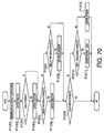
using FIG.70. FIG.70 is processing flowchart that
describes the operation of the data adaptation section
100.
The policy engine 101 identifies the display screen
size and number of display colors as the terminal
capability according to terminal preferences d1002
obtained from the terminal 105 (P1201). The policy engine
101 then controls the content selection section 103 and
content manipulation section 104 according to the
information and policy identified in P1201.
The content analysis section 102 analyzes the
physical data type of Internet content d1001 requested
by the user (P1202). Then, the content selection section
103 judges whether display of the Internet content d1001
is possible with the display capability of the terminal
105 (P1203), and if the capability is sufficient to display
the Internet content d1001, selects only content that
can be displayed with the terminal capability from the
Internet content d1001 (P1204).
Then, the content manipulation section 104 further
converts the displayable content selected in P1204 to
a form that can be displayed with the terminal capability .
Specifically, the content selection section 103 judges
whether the content is larger than the display screen
size (P1205), and content larger than the display screen
size is reduced in size by the content manipulation section
104 (P1206). If the content is not larger than the display
screen size, the content manipulation section 104 judges
whether the content is smaller than the display capability
(P1207), and small content is enlarged by the content
manipulation section 104 (P1208).
The content manipulation section 104 also judges
whether the number of display colors of the terminal 105
are colors (P1209). Then, if the number of display colors
of the terminal 105 are not colors, the content
manipulation section 104 judges whether they are
gray-scale (P1210), and if they are gray-scale, converts
the content number of colors to gray-scale (P1211), and
if they are neither colors nor gray-scale, performs binary
conversion (P1212).
However, with the above-described conventional
technology, a general policy is carried out-that is,
selection and manipulation of content based on the result
of content analysis in accordance with a policy suited
to a specific terminal. Consequently, there is a problem
in that it is only possible to perform data adaptation
according to a predetermined fixed number of terminal
patterns.
Also, with the conventional technology, it is not
possible to perform selection and manipulation of content
according to the preferences of the user: for example,
selection and manipulation to display part of an image
rather than reducing it in size. Therefore, with the
conventional technology, even in a case where content
selection and manipulation are performed using a
predetermined specific terminal, there is a problem in
that the user cannot perform data adaptation of content
in a form according to his or her preferences using that
terminal.
Disclosure of Invention
It is a first objective of the present invention
to perform data adaptation of content in a form according
to the user's preferences by selecting a data segment
according to user preference information.
It is a second objective of the present invention
to perform data adaptation of content, when content is
distributed via a network, in a form in which the user
wishes to receive it and in a scalable fashion according
to the network status.
In order to meet the above-described first objective,
the present invention performs data adaptation in a form
the user wishes to see for each content by holding user
preference information as user preferences, selecting
a data segment according to the user preferences, and
performing resolution conversion on the basis of the
segment priority and terminal capability. By this means,
it is possible to perform data adaptation fully in
accordance with the user's preferences.
Also, in order to meet the above-described second
objective, the present invention performs data adaptation
of content in a form in which the user wishes to receive
it and in a scalable fashion according to the network
status by acquiring information on the network
transmission band as a network preference when content
is distributed via a network, and adjusting the data
quantity according to the segment priority and
transmission band. By this means, it is possible to
perform data adaptation in a form in which the user wishes
to receive it and in a scalable fashion according to the
network status.
Brief Description of Drawings
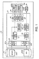
FIG.1 is a block diagram of a terminal provided with
a data adaptation apparatus according to Embodiment 1
and Embodiment 3 of the present invention;
FIG.2 is a detailed drawing of user preferences
according to Embodiment 1;
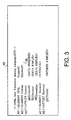
FIG.3 is a drawing showing description definitions
of user preferences according to Embodiment 1;
FIG.4 is a drawing showing a sample description of
user preferences according to Embodiment 1;
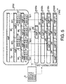
FIG.5 is an explanatory drawing of the operation
of the segment selection section according to Embodiment
1;
FIG.6 is a processing flowchart of the user adaptive
control section according to Embodiment 1;
FIG.7 is a processing flowchart of the terminal
adaptive control section according to Embodiment 1;
FIG.8 is a block diagram of a system provided with
a data adaptation apparatus according to Embodiment 2
and Embodiment 4 of the present invention;
FIG.9 is a processing flowchart of the network
adaptive control section according to Embodiment 2;
FIG.10 is a detailed drawing showing a second example
of user preferences;
FIG.11 is a detailed drawing showing second
description definitions of user preferences;
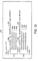
FIG.12 is a detailed drawing showing a second sample
description of user preferences;
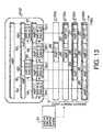
FIG.13 is a drawing explaining second operation of
the segment selection section;
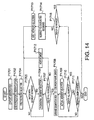
Fig.14 is a flowchart of second processing of the
user adaptive control section;
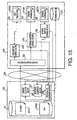
FIG.15 is a block diagram showing another example
of a system provided with a data adaptation apparatus
according to an embodiment of the present invention;
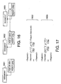
FIG.16 is a drawing showing another mode of segments
according to an embodiment of the present invention;
FIG.17 is a drawing showing examples of segment
descriptions according to an embodiment of the present
invention;
FIG.18 is a drawing showing the data structure
according to Embodiment 5 of the present invention;
FIG.19 is a drawing showing an example of data
descriptions according to Embodiment 5 of the present
invention;
FIG.20 is a drawing showing another example of the
data structure according to Embodiment 5 of the present
invention;
FIG. 21 is a drawing showing another example of
descriptions of the data structure according to
Embodiment 5 of the present invention;
FIG.22 is a drawing showing the data structure
according to Embodiment 6 of the present invention;
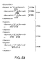
FIG.23 is a drawing showing an example of data
descriptions according to Embodiment 6 of the present
invention;
FIG.24 is a drawing showing the data structure
according to Embodiment 7 of the present invention;
FIG.25 is a drawing showing data descriptions
according to Embodiment 7 of the present invention;
FIG.26 is a drawing showing another example of the
data structure according to Embodiment 7 of the present
invention;
FIG. 27 is a drawing showing another example of
descriptions of a data structure according to Embodiment
7 of the present invention;
FIG.28 is a drawing showing the data structure
according to Embodiment 8 of the present invention;
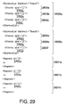
FIG.29 is a drawing showing data descriptions
according to Embodiment 8 of the present invention;
FIG.30 is a drawing showing another example of the
data structure according to Embodiment 8 of the present
invention;
FIG. 31 is a drawing showing another example of
descriptions of a data structure according to Embodiment
8 of the present invention;
FIG.32 is a first drawing showing description
definitions of user preferences according to Embodiment
9 of the present invention;
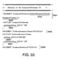
FIG.33 is a second drawing showing description
definitions of user preferences according to Embodiment
9 of the present invention;
FIG.34 is a drawing showing a sample description
of user preferences according to Embodiment 9 of the
present invention;
FIG.35 is a first drawing showing segment
description definitions according to Embodiment 9;
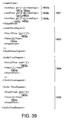
FIG.36 is a second drawing showing segment
description definitions according to Embodiment 9;
FIG.37 is a third drawing showing segment
description definitions according to Embodiment 9;
FIG.38 is a drawing showing a first sample segment
description according to Embodiment 9;
FIG.39 is a drawing showing a second sample segment
description according to Embodiment 9;
FIG.40 is a drawing showing a third sample segment
description according to Embodiment 9;
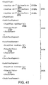
FIG.41 is a drawing showing a fourth sample segment
description according to Embodiment 9;
FIG.42 is a drawing showing a fifth sample segment
description according to Embodiment 9;
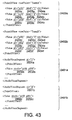
FIG.43 is a drawing showing a sixth sample segment
description according to Embodiment 9;
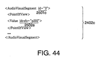
FIG.44 is a drawing showing a seventh sample segment
description according to Embodiment 9;
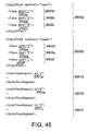
FIG.45 is a drawing showing an eighth sample segment
description according to Embodiment 9;
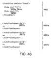
FIG.46 is a drawing showing a ninth sample segment
description according to Embodiment 9;
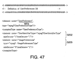
FIG.47 is a first drawing showing user preference
description definitions according to Embodiment 10 of
the present invention;
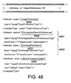
FIG.48 is a second drawing showing user preference
description definitions according to Embodiment 10;
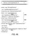
FIG.49 is a third drawing showing user preference
description definitions according to Embodiment 10;
FIG.50 is a fourth drawing showing user preference
description definitions according to Embodiment 10;
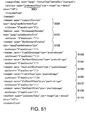
FIG.51 is a fifth drawing showing user preference
description definitions according to Embodiment 10;
FIG.52 is a drawing showing a sample user preference
description according to Embodiment 10;
FIG.53 is a first drawing showing segment
description definitions according to Embodiment 10;
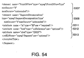
FIG.54 is a second drawing showing segment
description definitions according to Embodiment 10;
FIG.55 is a third drawing showing segment
description definitions according to Embodiment 10;
FIG.56 is a fourth drawing showing segment
description definitions according to Embodiment 10;
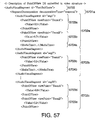
FIG.57 is a first drawing showing a sample segment
description according to Embodiment 10;
FIG.58 is a second drawing showing a sample segment
description according to Embodiment 10;
FIG.59 is a third drawing showing a sample segment
description according to Embodiment 10;
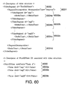
FIG.60 is a first drawing showing another example
of a segment description according to Embodiment 10;
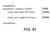
FIG.61 is a second drawing showing another example
of a segment description according to Embodiment 10;
FIG.62 is a first drawing showing digest description
definitions according to Embodiment 11;
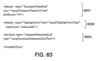
FIG.63 is a second drawing showing digest
description definitions according to Embodiment 11;
FIG.64 is a third drawing showing digest description
definitions according to Embodiment 11;
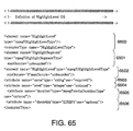
FIG.65 is a fourth drawing showing digest
description definitions according to Embodiment 11;
FIG.66 is a drawing showing an example of a point
of view list description according to an embodiment;
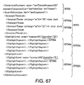
FIG.67 is a drawing showing an example of a digest
description according to Embodiment 11;
FIG.68 is a block diagram of a conventional data
adaptation apparatus;
FIG.69 is a detailed drawing of a conventional
terminal preference description; and
FIG.70 is a processing flowchart of a conventional
data adaptation section.
Best Mode for Carrying out the Invention
With reference now to the attached drawings,
embodiments of the present invention will be explained
in detail below.
(Embodiment 1)
A terminal provided with a data adaptation apparatus
according to Embodiment 1 of the present invention will
be described below. FIG.1 is a block diagram of a
terminal provided with a data adaptation apparatus
according to Embodiment 1. As shown in FIG.1, a terminal
10 is composed of a content data storage medium 11 on
which is stored data d102 consisting of content composed
of a plurality of segments and metadata d101 which is
information for describing the data d102, a user
preference storage section 19 that stores user
preferences d103 which comprise information relating to
the user's preferences, a terminal preference storage
section 20 that stores terminal preferences d104 which
comprise terminal capability information, and a user
adaptation section 12 that adapts the data d102 to the
user's preferences using the metadata d101, user
preferences d103, and terminal preferences d104.
The user adaptation section 12 is provided with means
for acquiring various kinds of data. Provided as means
for acquiring various kinds of data are a content data
acquisition section 21 consisting of a metadata
acquisition section 21a that acquires metadata d101 and
a data acquisition section 21b that acquires data d102,
a user preference acquisition section 22 that acquires
user preferences d103, and a terminal preference
acquisition section 23 that acquires terminal preferences
d104.
In addition, the user adaptation section 12 is
provided with means for selecting a predetermined segment
from the data d102 acquired in accordance with the user's
preferences and adapting it to the user's preferences.
Provided as means for adapting a selected segment to the
user's preferences are a user adaptive control section
14 that generates information for selecting a
predetermined segment from acquired data d102 using
acquired metadata d101 and user preference data d103,
and a segment selection section 16 that selects and
extracts a predetermined segment from acquired data d102
on the basis of information generated by the user adaptive
control section 14.
Moreover, the user adaptation section 12 is provided
with means for converting data d102 in accordance with
the terminal capability of, for instance, a display
section 18 which is a data d102 processing apparatus.
Provided as means for converting data d102 in accordance
with the terminal capability are a terminal adaptive
control section 15 that generates information for varying
the spatial resolution and color resolution of data d102
from metadata d101 and terminal preferences d104, and
a resolution conversion section 17 that performs spatial
resolution conversion and color resolution conversion
for data d102 in accordance with information generated
by the terminal adaptive control section 15.
Next, user preferences d103 will be described.
FIG.2 is a detailed drawing of user preferences d103.
As shown in FIG.2, user preferences d103 are composed
of a plurality of user preference descriptions 3a to 3n.
In user preference descriptions 3a to 3n are stored a
plurality of content identifiers 34 corresponding to each
of user preference descriptions 3a to 3n, duration
information 35 for displaying content at a desired time,
and sets of keywords (user points of view) 36a and 36b
for extracting a desired segment from content and priority
levels 37a and 37b corresponding to these keywords 36a
and 36b.
Next, a definition description of user preferences
d103 including user preference descriptions 3a to 3n will
be described in concrete terms. FIG.3 is a drawing
showing a definition description of user preferences
d103.
As shown in FIG.3, the user preference description
definition 40 is written using DTD (Document Type
Definition) of XML (extensible Markup Language).
The user preference description definition 40
defines there being at least one content item (Content)
in the user preferences as indicated by reference numeral
41 in the drawing. Also, it is defined that there is at
least one keyword (user point of view) 36 (Keyword) for
each content item as indicated by reference numeral 42
in the drawing. Further, a content identifier 34
(ContentID), duration 35 (Duration), and screen size 46
(ScreenSize) which is size information for displaying data,
are defined for the content as attributes as indicated
by reference numeral 43 in the drawing. Also, the keyword
36 (Keyword) is defined as being written as text data
as indicated by reference numeral 48 in the drawing. In
addition, it is defined that there is a priority level
37 (Priority) as an attribute for each keyword 36.
Next, user preferences created using the user
preference description definition shown in FIG.3 will
be described. FIG.4 is a drawing showing an example of
user preferences.
In FIG.4, the item denoted by reference numeral 50
is an example of an actual user preference description
written in XML using user preference description
definition 40.
User preferences 50 include two contents 51 and 52.
Content 51 has a content ID 53a (in this example, 123456789),
and content 52 has a content ID 53b (in this example,
123456788). Also, content 51 includes a display duration
54 (in this example, smpte=00:05:00:00) as a content
attribute.
In addition, content 51 includes keywords (user
points of view) 55a to 55c. Nakata is entered for keyword
55a, Soccer for keyword 55b, and Japan for keyword 55c.
Also, as attributes of keywords 55a to 55c, priority level
5 is entered for keyword 55a, priority level 4 for keyword
55b, and priority level 2 for keyword 55c.
Meanwhile, in content 52, a display scale 56 (in
this example, pixel = 320x240) is entered as a content
attribute. In addition, content 52 includes keywords 55d
to 55f. Headline is entered for keyword 55d, Stock for
keyword 55e, and Sports for keyword 55f. Also, as
attributes of keywords 55d to 55f, priority level 5 is
entered for keyword 55d, priority level 5 for keyword
55e, and priority level 3 for keyword 55f.
Next, the configuration of the data d102 will be
described using FIG.5.
The data d102 is composed of a segment 61 that
comprises the time range of the data d102. The segment
61 is composed of a first subsegment 62 and a second
subsegment 63. Subsegment 62 is composed of a first
subsegment 64 and a second subsegment 65, and subsegment
63 is composed of a first subsegment 66 and a subsegment
67. Thus, the data d102 has a hierarchical structure
comprising segments and subsegments.
Keywords (segment points of view) 621 are added to
subsegment 62, and keywords (segment points of view) 631
are added to subsegment 63. Also, keywords (segment
points of view) 641 are added to subsegment 64, keywords
(segment points of view) 651 are added to subsegment 65,
keywords (segment points of view) 661 are added to
subsegment 66, and keywords (segment points of view) 671
are added to subsegment 67.
Keywords 621, 631, 641, 651, 661, and 671 are entered
in the metadata d101. Also, a plurality of keywords (KWD)
indicating the contents of segments 62 to 67 corresponding
to keywords 621, 631, 641, 651, 661, and 671 are assigned
to keywords 621, 631, 641, 651, 661, and 671.
A segment priority (segment priority level) is
assigned to each keyword (KWD). In the example in the
drawing, keywords 621 are composed of a set of KWD#2 and
segment priority level 3 which is the ranking within KWD#2,
and a set of KWD#3 and segment priority level 3 which
is the ranking within KWD#2.
Next, the operation of the segment selection section
16 and the operation of the user adaptive control section
14 will be described using FIG.5 and FIG.6. FIG.5 is an
operation explanation drawing that explains the operation
of the segment selection section 16. FIG.6 is a
processing flowchart that explains the operation of the
user adaptive control section 14.
The content data acquisition section 21 of the data
adaptation section 12 reads and acquires metadata d101
and data d102 from the storage medium 11. Then, the user
adaptive control section 14 analyzes the acquired
metadata d101, extracts the data structure and at least
one segment point of view to be added to each segment
and the segment priority level at the segment point of
view, and identifies the data (content) d102 that has
been read (P701).
Next, the user adaptive control section 14 selects
the user preference description (for example, user
preference description 31) corresponding to the
identified content from the user preferences d103 (P702).
In addition, the user adaptive control section 14 arranges
the user points of view (keywords) included in user
preference description 31 in order of priority, which
is a user point of view attribute (P703). The user
adaptive control section 14 then selects the user point
of view that has been assigned the highest priority level
(P704).
Next, the user adaptive control section 14 sends
information to the segment selection section 16 such that
the segment that matches that user point of view is selected
from the data d102, in order from the highest-priority
user point of view (first user point of view).
The segment selection section 16 then compares the
first user point of view with the segment points of view
of the segments, using the information sent from the user
adaptive control section 14, and judges whether there
is a segment that has been assigned a segment point of
view that matches the first user point of view (P705).
Next, a transition is made to the operation to select
a segment that has been assigned a segment point of view
that matches the first user point of view.
However, if all segments that have been assigned
a segment point of view that matches the first user point
of view are simply selected, it is possible that the
selected segments may exceed the restriction conditions
of the duration information 54 or spatial range
information 56, or both of these. Thus, in this
embodiment, all segments that have been assigned a segment
point of view that matches the first user point of view
are first provisionally selected, and then a number of
segments that does not exceed the restriction conditions
of the duration information 54 or spatial range
information 56, or both of these, is actually selected
from the provisionally selected segments.
To be specific, the segment selection section 16
first provisionally selects segments that conform to the
user point of view (P706), then the segment selection
section 16 judges whether provisional selection has been
completed for all segments included in the metadata d101
(P707), and if it has not been completed, extracts the
next segment using the metadata d101, and performs
processing P705 and P706. In this way, provisional
selection can be performed for all the segments included
in the data d102.
Then, if the data adaptation section 12 judges in
P707 that provisional selection has been completed for
all the segments, the provisionally selected segments
are arranged in the order of segment priority assigned
to the segments (P708). This is done in order to make
the actual selection of segments starting from the segment
with the highest segment priority level in the actual
segment selection process that will be described later.
First the data adaptation section 12 performs actual
selection of the segment with the highest segment priority
(P709). Next, the data adaptation section 12 judges
whether actual selection has been completed for all
provisionally selected segments (P710). Then, if the
data adaptation section 12 judges in P710 that actual
selection has not been completed for all provisionally
selected segments, it judges whether the data length of
the actually selected segments exceeds the restriction
conditions of duration or spatial range, or both of these
(P711). The data adaptation section 12 then repeats the
operations from P709 to P711 as long as these restriction
conditions are not exceeded.
If the data adaptation section 12 judges in P710
that actual selection has been completed for all
provisionally selected segments, it judges whether
processing has been performed for all user points of view
(keywords) (P715). If the data adaptation section 12
judges in P715 that processing has been completed for
all user points of view, it terminates processing. If,
on the other hand, the data adaptation section 12 judges
in P715 that processing has not been completed for all
user points of view, a transition is made to processing
for the next user point of view.
Here, performing processing and selection again for
segments already selected in the above-described
processing would be pointless. Therefore, the data
adaptation section 12 first extracts unselected segments
and performs the following processing on the unselected
segments only (P714). The data adaptation section 12 then
selects the next user point of view (P713) and performs
processing P705 to P711.
The segment selection operation will now be
described in concrete terms using FIG.5. First, the data
adaptation section 12 looks for a subsegment with KWD#1,
which has the highest segment priority level of the user
points of view ( keywords ) included in the user preferences
(user preference description) 3. Keywords 631 of
subsegment 63 and keywords 661 of subsegment 66 both have
KWD#1. Next, the data adaptation section 12 adds a
duration restriction to subsegment 63 and subsegment 66,
and makes a selection from subsegment 63 and subsegment
66 in order of stringency of the duration restriction.
To be specific, subsegment 66 for which the duration
restriction is not stringent-that is, duration is
short-is selected with top priority as output data d102a.
Then, subsegment 63 is selected as the segment making
up output data 102b.
Similarly, the data adaptation section 12 looks for
a subsegment with KWD#2, which has the next-highest
priority level of the user points of view included in
the user preferences 3. KWD#2 is included in all the
subsegments making up segment 61. Therefore, it is
necessary here to decide which subsegment is to be given
priority.
To be specific, the data adaptation section 12
compares the segment priority levels of the segment points
of view added to each subsegment. In the example in FIG.5,
subsegment 63, subsegment 62, subsegment 65, and
subsegment 66 have the same priority, followed in priority
by subsegment 64 and subsegment 67. Since subsegment 67
has already been selected, it is omitted from the items
subject to the following processing.
Therefore, after the data adaptation section 12 has
selected output data d102b, if further duration
restrictions are permitted, subsegment 65, which has a
higher segment priority level than subsegment 64, is
selected in addition to subsegment 63 as a subsegment
making up output data 102c. The remaining subsegment 64
includes KWD#2 and KWD#3, and has a lower segment priority
level than subsegment 65. Therefore, when duration
restrictions are most lenient, subsegment 64 is selected
in addition to subsegment 63 and subsegment 65 as a
subsegment making up output data stream 102d.
The user adaptive control section 14 updates the
priority level of a user point of view included in user
preferences d103 that coincides with a keyword according
to the priority level of the keyword added to a selected
segment.
In this way, it is possible to select segments
suitable for user preferences d103 from data d102, and
adapt data d102 to user preferences d103.
Next, the data adaptation section 12 shifts to an
operation for converting the segments selected as
described above according to the terminal preferences
d104 that constitute terminal capability information.
The operation of the terminal adaptive control section
15 will be described below using FIG.7. FIG.7 is a
processing flowchart explaining the operation of the
terminal adaptive control section 15.
First, the terminal adaptive control section 15
acquires the terminal preferences d104 to be recorded
in the terminal 10, and identifies the screen display
size and number of display colors of the display section
18 as terminal capabilities (P801). Next, the terminal
adaptive control section 15 determines the segment
priority level that the segment selected by the segment
selection section 16 has as its own attribute (P802).
Then the terminal adaptive control section 15 judges
whether the selected segment is larger than the display
capability of the display section 18 of the terminal 10
(P803).
If the terminal adaptive control section 15 judges
in P803 that the selected segment is larger than the display
capability of the display section 18 of the terminal 10,
the terminal adaptive control section 15 adds a segment
priority level to the terminal preferences d104, and
determines whether to reduce the entire segment in size,
display part of the selected segment, not display part
of the selected segment, or convert part of the selected
segment before displaying it (P804).
If, on the other hand, the terminal adaptive control
section 15 judges in P803 that the selected segment is
not larger than the display capability of the display
section 18 of the terminal 10, the terminal adaptive
control section 15 judges whether the data of the selected
segment is smaller than the screen display size of the
display section 18 (P805). If the terminal adaptive
control section 15 judges in P805 that the data of the
selected segment is smaller than the screen display size
of the display section 18, the terminal adaptive control
section 15 adds a segment priority to the terminal
preferences d104, and determines whether to enlarge the
entire segment, enlarge part of the selected segment,
not display part of the selected segment, or convert part
of the selected segment before displaying it (P806).
Next, the terminal adaptive control section 15
identifies the number of terminal display colors from
the terminal preferences d104, and, in accordance with
the number of terminal display colors, judges whether
the segment for which processing P801 to P806 was executed
is capable of color display by the display section 18
(P807). If the terminal adaptive control section 15
determines in P807 that the segment for which the
above-described processing was executed is capable of
color display by the display section 18, processing is
terminated.
If, on the other hand, the terminal adaptive control
section 15 determines in P807 that the segment for which
the above-described processing was executed is not
capable of color display by the display section 18, it
is determined whether the segment for which the
above-described processing was executed can be displayed
by the display section 18 after gray-scale conversion
(P808). Then, if the terminal adaptive control section
15 determines that the segment for which the
above-described processing was executed is displayable
by the display section 18 after gray-scale conversion,
it is determined that the segment for which the
above-described processing was executed is to be
subjected to gray-scale conversion (P809). If the
terminal adaptive control section 15 determines that the
segment for which the above-described processing was
executed is not displayable by the display section 18
after gray-scale conversion, it is determined that the
segment for which the above-described processing was
executed is to be subjected to binary conversion (P810).
The resolution conversion section 17 then adapts
the contents of the decision by the terminal adaptive
control section 15 for the actually selected segment and
performs resolution conversion. Then the display
section 18 displays the segment converted by the
resolution conversion section 17.
As described above, according to Embodiment 1, one
or more segment points of view added to segments in the
metadata d101, and segment priority levels in the segment
points of view, are extracted, and segment selection can
be performed based on the segment priority of segments
that have a segment point of view that matches a user
point of view included in the user preferences d103. By
this means, it is possible to perform data adaptation
of data d102 fully in accordance with the user's
preferences.
Also, according to Embodiment 1, it is possible to
perform data adaptation fully in accordance with terminal
capability by performing temporal and spatial resolution
conversion of segments according to terminal capability
information included in terminal preferences.
Moreover, according to Embodiment 1, the mode is
such that a user priority level is assigned to each user
point of view, and therefore relative user point of view
priority levels can be changed by changing user priority
levels alone. Consequently, editing of user points of
view by the user is simplified.
(Embodiment 2)
A data adaptation apparatus according to Embodiment
2 of the present invention will be described below using
FIG.8. FIG.8 shows a block diagram of a data adaptation
apparatus according to Embodiment 2.
In Embodiment 2, the user adaptive control section
according to Embodiment 1 is provided with a server, and
the server and terminals are connected by a network.
However, simply providing network connection of a user
adaptive control section and terminals does not make it
possible to perform data adaptation in a scalable fashion
in the form the user wishes to receive and according to
the status of the network. To solve this problem, in
Embodiment 2, when distributing content to terminals via
a network, the user adaptation section acquires
information on the network transmission band as network
preferences and adjusts the data quantity according to
the segment priority and transmission band. In this way,
Embodiment 2 enables data adaptation to be performed in
a scalable fashion in the form the user wishes to receive
and according to the status of the network.
Embodiment 2 will now be described in detail below.
The configuration of a data adaptation section 22
according to Embodiment 2 will be described using FIG.8.
FIG.8 is a block diagram of a system provided with a data
adaptation apparatus 22 according to Embodiment 2.
As shown in FIG.8, a server 20 and terminal 2B are
connected by a network 2A. The terminal 2B is composed
of a user preference storage section 30 that stores user
preferences d103 which comprise information relating to
the user's preferences, a terminal preference storage
section 31 that stores terminal preferences d104 which
comprise terminal 2B capability information, a network
preference storage section 205 that stores network
preferences d205 which comprise network 2A transmission
band information, and a storage medium 2C that stores
data sent from the server 20.
The server 20 is composed of a content data storage
medium 21 on which is stored data d102 consisting of content
composed of a plurality of segments and metadata d101
which is information for describing the data d102, and
a user adaptation section 22 that adapts the data d102
to the user's preferences using the metadata d101, user
preferences d103, terminal preferences d104, and network
preferences d205.
The user adaptation section 22 is provided with means
for acquiring various kinds of data. Provided as means
for acquiring various kinds of data are a content data
acquisition section 33 consisting of a metadata
acquisition section 33a that acquires metadata d101 and
a data acquisition section 33b that acquires data d102,
a user preference acquisition section 34 that acquires
user preferences d103 via the network 2A, a terminal
preference acquisition section 35 that acquires terminal
preferences d104 via the network 2A, and a network
preference acquisition section 36 that acquires network
preferences d205 via the network 2A.
In addition, the user adaptation section 12 is
provided with means for selecting a predetermined segment
from the data d102 acquired in accordance with the user's
preferences and adapting it to the user's preferences.
Provided as means for adapting a selected segment to the
user's preferences are a user adaptive control section
24 that generates information for selecting a
predetermined segment from acquired data d102 using
acquired metadata d101 and user preference data d103,
and a segment selection section 26 that selects and
extracts a predetermined segment from acquired data d102
on the basis of information generated by the user adaptive
control section 24.
Moreover, the user adaptation section 24 is provided
with means for converting data d102 in accordance with
the capability of the terminal 2B which is a data d102
processing apparatus. Provided as means for converting
data d102 in accordance with the terminal capability are
a terminal adaptive control section 25 that generates
information for varying the spatial resolution and color
resolution of data d102 from metadata d101 and terminal
preferences d104, a resolution conversion section 27 that
performs spatial resolution conversion and color
resolution conversion for d102 in accordance with
information generated by the terminal adaptive control
section 25, a network adaptive control section 28 that
generates information for adjusting the quantity of data
d102 sent to the network 2A using the metadata d101 and
network preferences d205, and a data quantity adjustment
section 29 that adjusts the quantity of data sent to the
network 2A according to information generated by the
network adaptive control section 28.
Next, the operation of the segment selection section
26 and the operation of the user adaptive control section
24 will be described using FIG.6.
The content data acquisition section 33 of the data
adaptation section 24 reads and acquires metadata d101
and data d102 from the storage medium 21. Then, the user
adaptive control section 24 analyzes the acquired
metadata d101, extracts the data structure and at least
one segment point of view to be added to each segment
and the segment priority level at the segment point of
view, and identifies the data (content) d102 that has
been read (P701). Next, the user adaptive control
section 24 selects the user preference description (for
example, user preference description 31) corresponding
to the identified content from the user preferences d103
(P702). In addition, the user adaptive control section
24 arranges the user points of view (keywords) included
in user preference description 31 in order of priority
level, which is a user point of view attribute (P703).
The user point of view that has been assigned the highest
priority level is then selected (P704).
Next, the user adaptive control section 24 sends
information to the segment selection section 26 such that
a segment that matches that user point of view is selected
from the data d102, in order from the highest-priority
user point of view (first user point of view).
The segment selection section 26 then compares the
first user point of view with the segment points of view
of the segments, using the information sent from the user
adaptive control section 24, and judges whether there
is a segment that has been assigned a segment point of
view that matches the first user point of view (P705).
Next, a transition is made to the operation to select
a segment that has been assigned a segment point of view
that matches the first user point of view.
The segment selection section 26 first
provisionally selects segments that conform to the user
point of view (P706). Then the segment selection section
26 judges whether provisional selection has been
completed for all segments included in the metadata d101
(P707), and if it has not been completed, extracts the
next segment using the metadata d101, and performs
processing P705 and P706. In this way, provisional
selection can be performed for all the segments included
in the data d102.
Then, if the data adaptation section 22 judges in
P707 that provisional selection has been completed for
all the segments, the provisionally selected segments
are arranged in the order of segment priority assigned
to the segments (P708). This is done in order to make
the actual selection of segments starting from the segment
with the highest segment priority level in the actual
segment selection process that will be described later.
First, the data adaptation section 22 performs
actual selection of the segment with the highest segment
priority level (P709). Next, the data adaptation section
22 judges whether actual selection has been completed
for all provisionally selected segments (P710). Then,
if the data adaptation section 22 judges in P710 that
actual selection has not been completed for all
provisionally selected segments, it judges whether the
data length of the actually selected segments exceeds
the restriction conditions of duration or spatial range,
or both of these (P711). The data adaptation section 22
then repeats the operations from P709 to P711 as long
as these restriction conditions are not exceeded.
If the data adaptation section 22 judges in P710
that actual selection has been completed for all
provisionally selected segments, it judges whether
processing has been performed for all user points of view
(keywords) (P715). If the data adaptation section 22
judges in P715 that processing has been completed for
all user points of view (keywords), it terminates
processing. If, on the other hand, the data adaptation
section 22 judges in P715 that processing has not been
completed for all user points of view, a transition is
made to processing for the next user point of view.
Here, performing processing and selection again for
segments already selected in the above-described
processing would be pointless. Therefore, the data
adaptation section 22 first extracts unselected segments
and performs the following processing on the unselected
segments only (P714). It then selects the next user point
of view (P713) and performs processing P705 to P711.
In this way, it is possible to select segments
suitable for user preferences d103 from data d102, and
adapt data d102 to user preferences d103.
Next, the data adaptation section 12 shifts to an
operation for converting the segments selected as
described above according to the terminal preferences
d104 that constitute terminal capability information.
The operation of the terminal adaptive control section
25 will be described below using FIG.7.
First, the terminal adaptive control section 25
acquires the terminal preferences d104 to be recorded
in the terminal 2B from the terminal preference
acquisition section 35, and identifies the screen display
size and number of display colors of the display section
18 as terminal capabilities (P801). Next, the terminal
adaptive control section 55 determines the segment
priority level that the segment selected by the segment
selection section 26 has as its own attribute (P802).
Then the terminal adaptive control section 25 judges
whether the selected segment is larger than the display
capability of the display section 18 of the terminal 2B
(P803).
If the terminal adaptive control section 25 judges
in P803 that the selected segment is larger than the display
capability of the terminal 2B, the terminal adaptive
control section 25 adds a segment priority level to the
terminal preferences d104, and determines whether to
reduce the entire segment in size, display part of the
selected segment, not display part of the selected segment,
or convert part of the selected segment before displaying
it (P804).
If, on the other hand, the terminal adaptive control
section 25 judges in P803 that the selected segment is
not larger than the display capability of the terminal
2B, the terminal adaptive control section 25 judges
whether the data of the selected segment is smaller than
the screen display size of the terminal 2B (P805). If
the terminal adaptive control section 25 judges in P805
that the data of the selected segment is smaller than
the screen display size of the terminal 2B, the terminal
adaptive control section 25 adds a segment priority level
to the terminal preferences d104, and determines whether
to enlarge the entire segment, enlarge part of the selected
segment, not display part of the selected segment, or
convert part of the selected segment before displaying
it (P806).
Next, the terminal adaptive control section 25
identifies the number of terminal 2B display colors from
the terminal preferences d104, and, in accordance with
the number of terminal display colors, judges whether
the segment for which processing P801 to P806 was executed
is capable of color display by the display section (P807).
If the terminal adaptive control section 25 determines
in P807 that the segment for which the above-described
processing was executed is capable of color display by
the terminal 2B, processing is terminated.
If, on the other hand, the terminal adaptive control
section 25 determines in P807 that the segment for which
the above-described processing was executed is not
capable of color display by the terminal 2B, it is
determined whether the segment for which the
above-described processing was executed can be displayed
by the terminal 2B after gray-scale conversion (P808).
Then, if the terminal adaptive control section 25
determines that the segment for which the above-described
processing was executed is displayable by the display
section 18 after gray-scale conversion, it is determined
that the segment for which the above-described processing
was executed is to be subjected to gray-scale conversion
(P809). If the terminal adaptive control section 25
determines that the segment for which the above-described
processing was executed is not displayable by the terminal
2B after gray-scale conversion, it is determined that
the segment for which the above-described processing was
executed is to be subjected to binary conversion (P810).
The resolution conversion section 27 then adapts
the contents of the decision by the terminal adaptive
control section 25 for the actually selected segment and
performs resolution conversion. Then the data subjected
to resolution conversion is sent to the data quantity
adjustment section 29.
Next, the operation of the network adaptive control
section 28 will be described using FIG.9. FIG.9 is a
processing flowchart of the network adaptive control
section 28 according to Embodiment 2.
The network adaptive control section 28 acquires
from the network preference acquisition section 36
network preferences d205 sent from the terminal 2B via
the network 2A. Then the network adaptive control section
28 identifies the transmission band of the network 2A
(P901). Next, the network adaptive control section 28
determines the segment priority level that the segment
selected by the segment selection section 26 has as its
own attribute (P902). The network adaptive control
section 28 then judges whether the converted data is larger
than the transmission band (P903).
If the network adaptive control section 28 judges
in P903 that the converted data is larger than the
transmission band, the network adaptive control section
28 determines whether to compress all the data, transmit
part of the data, not transmit all the data, or convert
part of the data before transmitting it (P904). Here,
converting the data before transmitting it refers to
format conversion such as converting MPEG1 data to MPEG4
data or converting AAC data to MP3 data.
If, on the other hand, the network adaptive control
section 28 judges in P903 that the converted data is not
larger than the transmission band, the network adaptive
control section 28 judges whether the converted segment
data is smaller than the transmission band (P905). If
the network adaptive control section 28 judges in P905
that the converted data is smaller than the transmission
band, the network adaptive control section 28 determines
whether to perform additional transmission of
untransmitted data, not transmit, or transmit after
converting or restoring conversion to its original state
(P906).
The data quantity adjustment section 29 then adapts
the contents of the decision by the network adaptive
control section 28 for the actually selected segment,
adjusts the data quantity, and transmits it to the terminal
2B. The terminal 2B records the received segment in the
storage medium 2C.
As described above, according to Embodiment 2, in
addition to the effects of Embodiment 1, by adjusting
the selected segment data quantity according to the
transmission band included in the network preferences
d205, it is possible to perform data adaptation in a
scalable fashion in the form the user wishes to receive
and in accordance with the status of the network.
(Embodiment 3)
A data adaptation apparatus according to Embodiment
3 of the present invention will now be described below.
The configuration of the data adaptation apparatus
according to Embodiment 3 is identical to the
configuration of the data adaptation apparatus according
to Embodiment 1, and therefore a description of the
configuration of the data adaptation apparatus according
to Embodiment 3 will be omitted.
The data adaptation apparatus according to
Embodiment 3 and the data adaptation apparatus according
to Embodiment 1 differ in the configuration of the user
preferences d103. The user preferences d103 according
to Embodiment 3 will be described below. FIG.10 is a
second detailed drawing of user preferences d103.
As shown in FIG.10, user preferences d103 are
composed of a plurality of user preference descriptions
131 to 133. In user preference descriptions 131 to 133
are stored a plurality of content identifiers 134
corresponding to each of user preference descriptions
131 to 133, duration information 135 for displaying
content, and keywords 136a and 136b for extracting a
predetermined segment from content. Thus, priority
levels corresponding to keywords 136a and 136b are not
stored in the user preferences of Embodiment 3. This is
a point of difference between the user preferences of
Embodiment 3 and the user preferences of Embodiment 1.
Next, a definition description of user preferences
d103 including user preference descriptions 131 to 133
will be described in concrete terms . FIG.11 is a drawing
showing a definition description of user preferences
d103.
As shown in FIG.11, the user preference description
definition 140 is written using DTD (Document Type
Definition) of XML (extensible Markup Language).
The user preference description definition 140
defines there being at least one content (Content) in
the user preferences as indicated by reference numeral
141 in the drawing. Also, it is defined that there is
at least one keyword 136 (Keyword) for each content as
indicated by reference numeral 142 in the drawing.
Further, a content identifier 134 (ContentID), duration
135 (Duration), and screen size 144 (ScreenSize)which
is size information for displaying data, are defined for
the content as attributes as indicated by reference
numeral 143 in the drawing. Also, the keyword 136
(Keyword) is defined as being written as text data as
indicated by reference numeral 148 in the drawing.
It can also be see from the user preference
description definition 140 in FIG.11 that a priority level
corresponding to the keyword 136 is not stored in the
user preferences of Embodiment 3.
Next, user preferences created using the user
preference description definition shown in FIG.11 will
be described. FIG.12 is a drawing showing an example of
user preferences.
In FIG.12, reference numeral 150 denotes an example
of an actual user preference description written in XML
using user preference description definition 40.
User preferences 150 shown in FIG.12 include two
content entities 151 and 152. Content 151 has a content
ID 153a (in this example, 123456789), and content 152
has a content ID 153b (in this example, 123456788). Also,
content 151 includes a display duration 154 (in this
example, smpte=00:05:00:00) as a content attribute. In
addition, content 151 includes keywords 155a to 155c.
Nakata is entered for keyword 155a, Soccer for keyword
155b, and Japan for keyword 155c.
Meanwhile, in content 152, a display scale 156 (in
this example, pixel = 320x240) is entered as a content
attribute. In addition, content 152 includes keywords
155d to 155f. Headline is entered for keyword 155d, Stock
for keyword 155e, and Sports for keyword 155f.
Next, the configuration of data d102 according to
Embodiment 3 will be described using FIG.13. FIG.13 is
an operation explanation drawing explaining the operation
of the segment selection section 16. In FIG.13, the item
denoted by reference number 131 is a user preference
description. Apart from the user preference description
131, the configuration is similar to that of Embodiment
1.
Next, the operation of the segment selection section
16 and the operation of the user adaptive control section
14 will be described using FIG.13 and FIG.14. FIG.13 is
an operation explanation drawing that explains the
operation of the segment selection section 16. FIG.14
is a processing flowchart that explains the operation
of the user adaptive control section 14.
The content data acquisition section 21 of the data
adaptation section 12 reads and acquires metadata d101
and data d102 from the storage medium 11. Then, the user
adaptive control section 14 analyzes the acquired
metadata d101, extracts the data structure and at least
one segment point of view to be added to each segment
and the segment priority level at the segment point of
view, and identifies the data (content) d102 that has
been read (P1701). Next, the user adaptive control
section 14 selects the user preference description (for
example, user preference description 131) corresponding
to the identified content from the user preferences d103
(P1702). In addition, the user adaptive control section
14 arranges the user points of view (keywords) included
in user preference description 131 in the order in which
they are written. In the example in FIG.12, the keywords
are arranged in order starting from the keyword written
in the top line-that is, in the order keyword 155a, keyword
155b, keyword 155c. Then the first user point of
view-that is, the one written at the top-is selected
(P1704). The reason for arranging the keywords in the
order in which they are written in this way is that, since
user priority levels are not assigned to user preferences
d103 according to Embodiment 3, it is necessary to assign
some kind of priority levels corresponding to user
priorities. In Embodiment 3, the keyword priority levels
are made to correspond to the order in which they are
written, as a substitute for user priority levels.
Next, the user adaptive control section 14 sends
information to the segment selection section 16 such that
a segment that matches that user point of view is selected
from the data d102, in order from the highest-priority
user point of view (first user point of view).
The segment selection section 16 then compares the
first user point of view with the segment points of view
of the segments, using the information sent from the user
adaptive control section 14, and judges whether there
is a segment that has been assigned a segment point of
view that matches the first user point of view (P1705).
Next, a transition is made to the operation to select
a segment that has been assigned a segment point of view
that matches the first user point of view.
The segment selection section 16 first
provisionally selects segments that conform to the user
point of view (P1706). Then the segment selection section
16 judges whether provisional selection has been
completed for all segments included in the data d102
(P1707), and if it has not been completed, extracts the
next segment using the metadata d101, and performs
processing P1705 and P1706. In this way, provisional
selection can be performed for all the segments included
in the data d102.
Then, if the data adaptation section 12 judges in
P1707 that provisional selection has been completed for
all the segments, the provisionally selected segments
are arranged in the order of segment priority assigned
to the segments (P1708). This is done in order to make
the actual selection of segments starting from the segment
with the highest segment priority level in the actual
segment selection process that will be described later.
First the data adaptation section 12 performs actual
selection of the segment with the highest segment priority
level (P1709). Next, the data adaptation section 12
judges whether actual selection has been completed for
all provisionally selected segments (P1710). Then, if
the data adaptation section 12 judges in P1710 that actual
selection has not been completed for all provisionally
selected segments, it judges whether the data length of
the actually selected segments exceeds the restriction
conditions of duration or spatial range, or both of these
(P1711). The data adaptation section 12 then repeats the
operations from P1709 to P1711 as long as these restriction
conditions are not exceeded.
If the data adaptation section 12 judges in P1710
that actual selection has been completed for all
provisionally selected segments, it judges whether
processing has been performed for all user points of view
(keywords) (P1715). If the data adaptation section 12
judges in P1715 that processing has been completed for
all user points of view, it terminates processing. If,
on the other hand, the data adaptation section 12 judges
in P1715 that processing has not been completed for all
user points of view, a transition is made to processing
for the next user point of view.
Here, performing processing and selection again for
segments already selected in the above-described
processing would be pointless. Therefore, the data
adaptation section 12 first extracts unselected segments
and performs the following processing on the unselected
segments only (P1714). The data adaptation section 12
then selects the next user point of view (P1713) and
performs processing P1705 to P1711.
The segment selection operation will now be
described in concrete terms using FIG.13. First, the data
adaptation section 12 looks for a subsegment written in
the top line-that is with high-priority KWD#1-within the
user points of view (user keywords) included in the user
preferences (user preference description) 131.
Keywords 631 of subsegment 63 and keywords 661 of
subsegment 66 both have KWD#1. Next, the data adaptation
section 12 adds a duration restriction to subsegment 63
and subsegment 66, and makes a selection from subsegment
63 and subsegment 66 in order of stringency of the duration
restriction. To be specific, subsegment 66 for which the
duration restriction is not stringent-that is, duration
is short-is selected with top priority as output data
d102a. Then, subsegment 63 is selected as the segment
making up output data 102b.
Similarly, the data adaptation section 12 looks for
a subsegment with KWD#2, which has the next-highest
priority of the user points of view included in the user
preferences d103. KWD#2 is included in all the
subsegments making up segment 61. Therefore, it is
necessary here to decide which subsegment is to be given
priority.
To be specific, the data adaptation section 12
compares the segment priority levels of the segment points
of view added to each subsegment. In the example in FIG.13,
subsegment 63, subsegment 62, subsegment 65, and
subsegment 66 have the same priority level, followed in
priority by subsegment 64 and subsegment 67. Since
subsegment 67 has already been selected, it is omitted
from the items subject to the following processing.
Therefore, after the data adaptation section 12 has
selected output data d102b, if further duration
restrictions are permitted, subsegment 65, which has a
higher segment priority level than subsegment 64, is
selected in addition to subsegment 63 as a subsegment
making up output data 102c. The remaining subsegment 64
includes KWD#2 and KWD#3, and has a lower segment priority
level than subsegment 65, so when duration restrictions
are most lenient, subsegment 64 is selected in addition
to subsegment 63 and subsegment 65 as a subsegment making
up output data stream 102d.
The user adaptive control section 14 updates the
priority level of a user point of view included in user
preferences d103 that coincides with a keyword according
to the priority level of the keyword added to a selected
segment.
In this way, it is possible to select segments
suitable for user preferences d103 from data d102, and
adapt data d102 to user preferences d103.
Next, as in Embodiment 1, the terminal adaptive
control section 15 performs resolution conversion of the
selected segment sent from the segment selection section
16 in accordance with the flowchart shown in FIG.7.
As described above, according to Embodiment 3, it
is possible to perform processing using the order in which
user points of view are written for user point of view
priority levels, without assigning user priority levels
to the user preferences d103. By this means, it is
possible to perform data adaptation fully in accordance
with the user's preferences in the same way as with
Embodiment 1, without assigning user priority levels to
the user preferences d103.
Moreover, not providing user priority levels, as
in Embodiment 3, simplifies the data structure of the
user preferences d103.
(Embodiment 4)
A data adaptation apparatus according to Embodiment
4 of the present invention will now be described below.
In Embodiment 4, the user adaptive control section in
Embodiment 3 is provided in a server, and the server and
terminals are connected by a network.
The system that includes a data adaptation apparatus
according to Embodiment 4 has the same configuration as
a system that includes a data adaptation apparatus
according to Embodiment 2. Therefore, FIG.8 is a block
diagram of a system that includes a data adaptation
apparatus according to Embodiment 4.
The user preferences d103 according to Embodiment
4 are the same as in Embodiment 3. Therefore, the drawing
shown in FIG.10 is a drawing showing the user preferences
d103 according to Embodiment 4. Also, FIG.11 shows a
definition of user preferences according to Embodiment
4.
The operation of the segment selection section 26
according to Embodiment 4 is identical to that of the
segment selection section 26 according to Embodiment 3.
Therefore, FIG.13 is an operation explanation drawing
that explains the operation of the segment selection
section 26. In addition, FIG.14 is a processing flowchart
that explains the operation of the user adaptive control
section 24 according to Embodiment 4.
Moreover, the operation of the terminal adaptive
control section 25 according to Embodiment 4 is identical
to that of the terminal adaptive control section according
to Embodiment 3. Therefore, FIG.7 is a processing
flowchart explaining the operation of the terminal
adaptive control section 25 according to Embodiment 4.
Also, the operation of the network adaptive control
section 28 according to Embodiment 4 is identical to that
of the network adaptive control section 28 according to
Embodiment 2. Therefore, FIG.9 is a processing flowchart
explaining the operation of the network adaptive control
section 28 according to Embodiment 4.
A system including a data adaptation apparatus
according to Embodiment 4 will be described below using
these attached drawings.
The content data acquisition section 33 of the data
adaptation section 22 reads and acquires metadata d101
and data d102 from the storage medium 21. Then, the user
adaptive control section 24 analyzes the acquired
metadata d101, extracts the data structure and at least
one segment point of view to be added to each segment
and the segment priority level at the segment point of
view, and identifies the data (content) d102 that has
been read (P1701). Next, the user adaptive control
section 24 selects the user preference description (for
example, user preference description 131) corresponding
to the identified content from the user preferences d103
(P1702). In addition, the user adaptive control section
24 arranges the user points of view (keywords) included
in user preference description 131 in the order in which
they are written. In the example in FIG.12, the keywords
are arranged in order starting from the keyword written
in the top line-that is, in the order keyword 155a, keyword
155b, keyword 155c. Then the first user point of
view-that is, the one written at the top-is selected
(P1704). The reason for arranging the keywords in the
order in which they are written in this way is that, since
user priorities are not assigned to user preferences d103
according to Embodiment 4, it is necessary to assign some
kind of priority levels corresponding to user priorities.
In Embodiment 3, the keyword priority levels are set in
the order in which they are written, as a substitute for
user priorities.
Next, the user adaptive control section 24 sends
information to the segment selection section 26 such that
a segment that matches that user point of view is selected
from the data d102, in order from the highest-priority
user point of view (first user point of view).
The segment selection section 26 then compares the
first user point of view with the segment points of view
of the segments, using the information sent from the user
adaptive control section 24, and judges whether there
is a segment that has been assigned a segment point of
view that matches the first user point of view (P1705).
Next, a transition is made to the operation to select
a segment that has been assigned a segment point of view
that matches the first user point of view.
The segment selection section 26 first
provisionally selects segments that conform to the user
point of view (P1706). Then the segment selection section
26 judges whether provisional selection has been
completed for all segments included in the metadata d101
(P1707), and if it has not been completed, extracts the
next segment using the metadata d101, and performs
processing P1705 and P1706. In this way, provisional
selection can be performed for all the segments included
in the data d102.
Then, if the data adaptation section 22 judges in
P1707 that provisional selection has been completed for
all the segments, the provisionally selected segments
are arranged in the order of segment priority assigned
to the segments (P1708). This is done in order to make
the actual selection of segments starting from the segment
with the highest segment priority level in the actual
segment selection process that will be described later.
First the data adaptation section 22 performs actual
selection of the segment with the highest segment priority
level (P1709). Next, the data adaptation section 22
judges whether actual selection has been completed for
all provisionally selected segments (P1710). Then, if
the data adaptation section 22 judges in P1710 that actual
selection has not been completed for all provisionally
selected segments, it judges whether the data length of
the actually selected segments exceeds the restriction
conditions of duration or spatial range, or both of these
(P1711). The data adaptation section 22 then repeats the
operations from P1709 to P1711 as long as these restriction
conditions are not exceeded.
If the data adaptation section 22 judges in P1710
that actual selection has been completed for all
provisionally selected segments, it judges whether
processing has been performed for all user points of view
(keywords) (P1715). If the data adaptation section 22
judges in P1715 that processing has been completed for
all user points of view, it terminates processing. If,
on the other hand, the data adaptation section 22 judges
in P1715 that processing has not been completed for all
user points of view, a transition is made to processing
for the next user point of view.
Here, performing processing and selection again for
segments already selected in the above-described
processing would be pointless. Therefore, the data
adaptation section 22 first extracts unselected segments
and performs the following processing on the unselected
segments only (P1714). The data adaptation section 22
then selects the next user point of view (P1713) and
performs processing P1705 to P1711.
The segment selection operation will now be
described in concrete terms using FIG.13. First, the data
adaptation section 22 looks for a subsegment written in
the top line-that is with high-priority KWD#1-within the
user points of view (user keywords) included in the user
preferences (user preference description) 131.
Keywords 631 of subsegment 63 and keywords 661 of
subsegment 66 both have KWD#1. Next, the data adaptation
section 22 adds a duration restriction to subsegment 63
and subsegment 66, and makes a selection from subsegment
63 and subsegment 66 in order of stringency of the duration
restriction.
To be specific, subsegment 66 for which the duration
restriction is not stringent-that is, duration is
short-is selected with top priority as output data d102a.
Then, subsegment 63 is selected as the segment making
up output data 102b.
Similarly, the data adaptation section 22 looks for
a subsegment with KWD#2, which has the next-highest
priority of the user points of view included in the user
preferences d103. KWD#2 is included in all the
subsegments making up segment 61. Therefore, it is
necessary here to decide which subsegment is to be given
priority.
To be specific, the data adaptation section 22
compares the segment priority levels of the segment points
of view added to each subsegment. In the example in FIG.13,
subsegment 63, subsegment 62, subsegment 65, and
subsegment 66 have the same priority level, followed in
priority by subsegment 64 and subsegment 67. Since
subsegment 67 has already been selected, it is omitted
from the items subject to the following processing.
Therefore, after the data adaptation section 12 has
selected output data d102b, if further duration
restrictions are permitted, subsegment 65, which has a
higher segment priority level than subsegment 64, is
selected in addition to subsegment 63 as a subsegment
making up output data 102c. The remaining subsegment 64
includes KWD#2 and KWD#3, and has a lower segment priority
level than subsegment 65, so when duration restrictions
are most lenient, subsegment 64 is selected in addition
to subsegment 63 and subsegment 65 as a subsegment making
up output data stream 102d.
The user adaptive control section 24 updates the
priority level of a user point of view included in user
preferences d103 that coincides with a keyword according
to the priority level of the keyword added to a selected
segment.
In this way, it is possible to select segments
suitable for user preferences d103 from data d102, and
adapt data d102 to user preferences d103.
Next, as in Embodiment 1, the terminal adaptive
control section 25 performs resolution conversion of the
selected segment sent from the segment selection section
26 in accordance with the flowchart shown in FIG.7.
Next, the operation of the network adaptive control
section 28 will be described using FIG.9. FIG.9 is a
processing flowchart of the network adaptive control
section 28 according to Embodiment 4.
The network adaptive control section 28 acquires
from the network preference acquisition section 36
network preferences d205 sent from the terminal 2B via
the network 2A. Then the network adaptive control section
28 identifies the transmission band of the network 2A
(P901). Next, the network adaptive control section 28
determines the segment priority level that the segment
selected by the segment selection section 26 has as its
own attribute (P902). The network adaptive control
section 28 then judges whether the converted data is larger
than the transmission band (P903).
If the network adaptive control section 28 judges
in P903 that the converted data is larger than the
transmission band, the network adaptive control section
28 determines whether to compress all the data, transmit
part of the data, not transmit all the data, or convert
part of the data before transmitting it (P904).
If, on the other hand, the network adaptive control
section 28 judges in P903 that the converted data is not
larger than the transmission band, the network adaptive
control section 28 judges whether the converted segment
data is smaller than the transmission band (P905). If
the network adaptive control section 28 judges in P905
that the converted data is smaller than the transmission
band, the network adaptive control section 28 determines
whether to perform additional transmission of
untransmitted data, not transmit, or transmit after
converting or restoring conversion to its original state
(P906).
The data quantity adjustment section 29 then adapts
the contents of the decision by the network adaptive
control section 28 for the actually selected segment,
adjusts the data quantity, and transmits it to the terminal
2B. The terminal 2B records the received segment in the
storage medium 2C.
As described above, according to Embodiment 4, by
extracting the data structure and at least one point of
view to be added to each segment of the structure and
the segment priority level at the segment point of view,
performing segment selection based on the priority of
a point of view that coincides with a user point of view
included in user preferences, performing temporal and
spatial resolution conversion of selected segments
according to terminal capability information included
in terminal preferences, and adjusting the selected
segment data quantity according to the transmission band
included in network preferences, it is possible to perform
data adaptation in a scalable fashion in a form the user
wishes to receive and in accordance with the status of
the network.
In Embodiment 3 and Embodiment 4, user point of view
priority levels follow the order of description, but the
priority level of each user point of view may also be
represented by another description method, such as
reversing that order, or making an item located in the
middle of the description order the highest-level item.
Also, in Embodiment 2 and Embodiment 4, a mode is
described whereby a user adaptive control section 24,
terminal adaptive control section 25, and network
adaptive control section 28, which are control means,
are provided on the server 20 side as shown in FIG.8,
but a mode is also possible whereby a user adaptive control
section 24, terminal adaptive control section 25, and
network adaptive control section 28 are provided in a
terminal 2B.
In the case of this mode, metadata d102 is sent from
the server 20 to the terminal 2B, data d102 is subjected
to user adaptation by the terminal adaptive control
section 25 in the terminal 2B, and the result is sent
to the server 20. The server 20 then selects a segment
from the data d102 based on information sent from the
terminal adaptive control section 25, and transmits the
selected segment to the terminal 2B. A signal that
controls the resolution conversion section 27 of the
server 20 is sent from the terminal adaptive control
section 25 of the terminal 2B, and a signal that controls
the data quantity adjustment section 29 of the server
20 is sent from the network adaptive control section 28
of the terminal 2B. The resolution conversion section
27 and data quantity adjustment section 29 operate in
accordance with control signals sent from the terminal
2B, and the segment selection section 26 processes the
selected data and sends the processed segment to the
storage medium 2C of the terminal 2B.
Also, in the above-described sample embodiments,
a mode is described whereby one segment point of view
is assigned to a segment or subsegment. However, a mode
is also possible whereby, if there is a plurality of
segments or subsegments to which the same segment point
of view has been assigned, a segment point of view is
added to one of the segments or subsegments, and link
information for that segment point of view is assigned
to the other segments or subsegments.
By this means it is possible to represent the segment
point of view of a segment or subsegment by a link to
the segment point of view of another segment or subsegment.
This mode will be described in detail below using
FIG.16 and FIG.17. FIG.16 is a drawing showing another
mode of segments according to an embodiment of the present
invention. FIG.17 is a drawing showing examples of
segment descriptions according to an embodiment of the
present invention.
As can be seen from FIG.16, segment 1601 is a segment
that has the structure already described in Embodiment
1 to Embodiment 4. Segment 1601 is assigned a segment
point of view and a segment priority level.
Segment 1602 and segment 1603 are assigned the same
segment point of view. Segment 1603 is assigned link
information for segment 1602, and is linked to segment
1602.
Segment 1602 and segment 1603 will now be described
in detail using FIG.17.
Segment 1602 contains a segment point of view
(keyword) ID number (id) 1701. In this example, the ID
number 1701 is 1. Segment 1602 also contains a segment
priority level (P) 1702 corresponding to the keyword.
In this example, the segment priority level is 5. Also,
"TeamA" is entered as a keyword in segment 1602.
Segment 1603 contains a reference number (idref)
1703 for another segment point of view (keyword) which
is link information. In this example, the reference
number 1701 is 1. That is to say, segment 1603 references
a keyword whose ID number is 1.
Thus, the keyword of segment 1603 is "TeamA".
Segment 1603 contains a segment priority level (P) 1704
corresponding to the keyword. In this example, the
segment priority level is 2.
Linking segment keywords in this way makes it
unnecessary to enter keywords for all segments. In
addition, linking segment keywords makes explicit the
relationship between segments.
(Embodiment 5)
A data adaptation apparatus according to Embodiment
5 of the present invention will now be described below.
The system configuration of Embodiment 5 is the same as
that of Embodiment 1 to Embodiment 4.
In Embodiment 5, with regard to segment points of
view added to segments or subsegments, a table summarizing
all segment points of view to be registered (point of
view table) is provided as a content sub-element which
is an element of the top level of context structure
description data.
Next, the data structure according to Embodiment
5 will be described using FIG.18 and FIG.19. FIG.18 is
a drawing showing the data structure according to
Embodiment 5. FIG.19 is a drawing showing an example of
data descriptions according to Embodiment 5.
As can be seen from FIG.18, content has a point of
view table 1801 as a sub-element. In the point of view
table 1801 are stored a plurality of segment points of
view 1802a to 1802n included in the content.
Also, the content includes a plurality of segments
1803 to 1805. Segment 1803 is assigned link information
for the point of view table 1801, and is linked to segment
point of view 1802a of the point of view table 1801.
Segment 1804 is assigned link information for the point
of view table 1801, and is linked to segment point of
view 1802b of the point of view table 1801. Segment 1804
is assigned link information for the point of view table
1801, and is linked to segment point of view 1802c of
the point of view table 1801. Also, segments 1803 to 1805
are assigned segment priority levels corresponding to
the respective segment points of view.
Next, the data structure according to Embodiment
5 will be described in detail using FIG.19.
The point of view table 1801 contains segment points
of view 1802a to 1802c. Segment point of view 1802a
contains an ID number (id) 1901a. In this example, ID
number 1901a is 1. Also, segment point of view 1802a is
indicated by the text "A".
Segment point of view 1802b contains an ID number
(id) 1901b. In this example, ID number 1901b is 2. Also,
segment point of view 1802b is indicated by the text "B".
Segment point of view 1802c contains an ID number (id)
1901c. In this example, ID number 1901c is 3. Also,
segment point of view 1802c is indicated by the text "C" .
Meanwhile, segments 1803 to 1805 contain reference
numbers (idref) 1903a to 1903c, respectively, which are
link information for segment points of view 1802a to 1802c
of the point of view table 1801.
In this example, reference number 1903a of segment
1803 is 1. That is to say, segment 1803 references user
point of view 1802a whose ID number is 1. Therefore, the
keyword of segment 1803 is "A". Segment 1803 also
contains a segment priority level (P) 1904a corresponding
to the keyword. In this example, the segment priority
level is 2. Also, reference number 1903b of segment 1804
is 2. That is to say, segment 1804 references user point
of view 1802b whose ID number is 2. Therefore, the keyword
of segment 1804 is "B".
Segment 1804 also contains a segment priority level
(P) 1904b corresponding to the keyword. In this example,
the segment priority level is 3. Also, reference number
1903c of segment 1805 is 3. That is to say, segment 1805
references user point of view 1802c whose ID number is
3. Therefore, the keyword of segment 1805 is "C".
Segment 1805 also contains a segment priority level (P)
1904c corresponding to the keyword. In this example, the
segment priority level is 4.
Using this kind of configuration makes it easy to
present a segment point of view list to the user in advance.
By this means, the user can ascertain the segment points
of view that appear there before inputting a desired
segment point of view. Also, segment point of view input
by the user can be carried out by making a selection from
the point of view table.
A configuration may also be used whereby a pair
comprising a link to a corresponding point of view in
this point of view table and a corresponding score are
added to each segment or subsegment.
Also, the point of view table may have a
configuration for provision to a certain segment or
subsegment rather than content, and may use a special
description.
Moreover, it is also possible to mix pairs of link
to point of view list and score and pairs of point of
view and score, rather than representing all cases by
a link to the point of view list.
FIG.20 is a drawing showing a data configuration
with pairs of point of view and score mixed. As can be
seen from FIG.20, segments 1803 and 1804 that have link
information for the point of view table 1801 and a segment
2001 that does not have link information for the point
of view table 1801 are mixed in the content.
FIG. 21 shows sample descriptions of the data
configuration shown in FIG.20. As can be seen from this
drawing, it is not necessary to enter in the point of
view table 1801 all the segment points of view that appear
in the context contents description data, and only items
referenced by a link are included. Also, segment 2001
does not include link information for the point of view
table 1801.
(Embodiment 6)
A data adaptation apparatus according to Embodiment
6 of the present invention will now be described below.
In Embodiment 6, a point of view table showing a
list of segment points of view that appear in context
contents description data is provided, and is presented
to the user before input.
The data structure according to Embodiment 6 will
be described using FIG.22.
Content according to Embodiment 6 is composed of
a point of view table 2101 and a plurality of segments
2103 to 2105. Point of view table 2101 contains a
plurality of segment points of view 2102a to 2102n.
Segment point of view 2106 and segment priority level
2107 are contained in segment 2103, segment point of view
2108 and segment priority level 2109 in segment 2104,
and segment point of view 2110 and segment priority level
2122 in segment 2105. Unlike segments in Embodiment 5,
segments 2103 to 2105 do not contain link information
for point of view table 2101. That is to say, segments
2103 to 2105 and point of view table 2101 are configured
independently.
FIG.23 is a drawing showing an example of data
descriptions according to Embodiment 6 of the present
invention. As can be seen from FIG.23, points of view
2106, 2108, and 2110 included in segments 2103 to 2105
are stored in point of view table 2101. To be specific,
points of view 2301 to 2303 are stored for points of view
2106, 2108, and 2110.
Then point of view table 2101 is displayed before
the user inputs a user point of view.
By this means, the user can ascertain the segment
points of view that appear there before inputting a desired
user point of view. Another effect is that user point
of view input by the user can be carried out by making
a selection from the point of view table.
(Embodiment 7)
A data adaptation apparatus according to Embodiment
7 of the present invention will now be described below.
In Embodiment 7, when context contents description
data is to be represented so as to be capable of being
processed by a computer, it is represented divided into
a part that describes the structure and a part that
describes points of view, which are attributes, and their
scores.
Embodiment 7 will be described below using FIG.24
and FIG.25. FIG.24 is a drawing showing the data
structure according to Embodiment 7. FIG.25 is a drawing
showing data descriptions according to Embodiment 7.
Shown in the upper half of FIG.24 is the structure
part 2200a which describes the structure, and shown in
the lower half is the attribute part 2200b which describes
the attributes segment points of view and their priority
levels. The content of structure part 2200a includes
descriptions of a plurality of segments 2201a to 2201n.
In this drawing, the part describing the structure
describes the simplest structure, but configurations such
as described in other embodiments can also be handled.
Also, the attribute part 2200b includes
descriptions of a plurality of segment points of view
2202a and 2202b. Pairs of link information 2203a to 2203f
for the target segments and subsegments and priority
levels 2204a to 2204f relating to segment points of view
2202a and 2202b are assembled for each of segment points
of view 2202a and 2202b.
Next, the data structure according to Embodiment
7 will be described in detail using FIG.25.
As can be seen from FIG.25, the content includes
a plurality of segments 2201a to 2201c. Segment 2201a
is assigned a segment ID number (id) 2301a. In this
example, id 2301a is 1. Segment 2201b is assigned a
segment ID number (id) 2301b. In this example, id 2301b
is 2. Segment 2201n is assigned a segment ID number (id)
2301n. In this example, id 2301n is n.
Meanwhile, it can be seen from FIG.25 that segment
point of view 2202a is "TeamA". Also, segment point of
view 2202a includes a plurality of segment priority levels
2204a to 2204c. In this example, the priority level of
segment priority level 2204a is 3, the priority level
of segment priority level 2204b is 2, and the priority
level of segment priority level 2204c is 5.
Also, segment priority level 2202a is assigned
respective link information 2203a to 2203c. As link
information 2203a to 2203c, reference numbers idref for
referencing ID numbers 2301a to 2301c of segments 2201a
to 2201c are written. In this example, idref of segment
priority level 2204a is 1, idref of segment priority level
2204b is n, and idref of segment priority level 2204c
is 2. Thus, the target segment of segment priority level
2204a is segment 2201a, the target segment of segment
priority level 2204b is segment 2201c, and the target
segment of segment priority level 2204c is segment 2201n.
In this way it is possible to reference segments
2201a to 2201c from segment priority levels 2204a to 2204c.
Moreover, it can be seen from FIG.25 that segment
point of view 2202b is "TeamB". Also, segment point of
view 2202b includes a plurality of segment priority levels
2204d to 2204f. In this example, the priority level of
segment priority level 2204d is 4, the priority level
of segment priority level 2204e is 5, and the priority
level of segment priority level 2204f is 2.
Also, segment priority level 2202b is assigned
respective link information 2203d to 2203f. As link
information 2203d to 2203f, reference numbers idref for
referencing ID numbers 2301a to 2301c of segments 2201a
to 2201c are written. In this example, idref of segment
priority level 2204d is 2, idref of segment priority level
2204e is 3, and idref of segment priority level 2204f
is 1. Thus, the target segment of segment priority level
2204d is segment 2201b, the target segment of segment
priority level 2204e is segment 2201c, and the target
segment of segment priority level 2204f is segment 2201a
In this way it is possible to reference segments
2201a to 2201n from segment priority levels 2204a to 2204f.
Segment selection processing in the case of this
kind of data structure will now be described. First, the
above-described segment selection section 16 or 26
selects priority levels 2204a to 2204f for each of target
segment points of view 2202a and 2202b from the parts
contained in the attribute part 2200b. As selected
priority levels 2204a to 2204f are assigned link
information 2203a to 2203f respectively, it is possible
to select segments 2201a to 2201n which are the targets
of selected priority levels 2203a to 2203f. By this means,
segment selection sections 16 and 26 can select target
segments 2201a to 2201n by specifying a point of view
priority level 2204a point of view for each of segments
2202a and 2202b.
The same effect is obtained if the link information
2203a to 2203f and priority level 2204a to 2204f parts
are written separately rather than in the same file.
A mode can also be conceived whereby segments and
segment points of view are linked in both directions.
This mode will be described below using FIG.26 and
FIG.27. FIG.26 is a drawing showing a data structure
according to Embodiment 7. FIG. 27 is a drawing showing
data descriptions according to Embodiment 7.
As in Embodiment 7, the data in this mode, also,
is composed of a structure part 2400a and an attribute
part 2400b. The content of the structure part 2400a
includes descriptions of a plurality of segments 2401a
to 2401n. The attribute part 2400b includes descriptions
of a plurality of segment points of view 2402a and 2402b.
Pairs of link information 2403a to 2403f for the target
segments and subsegments and priority levels 2404a to
2404f relating to segment points of view 2402a and 2402b
are assembled for each of segment points of view 2402a
and 2402b.
Also, in this mode, since structure part 2400a and
attribute part 2400b are linked in both directions, link
information for segment priority levels 2402a to 2404f
is also included in segment 2401a to segment 2401n.
Next, the data structure according to this
embodiment will be described in detail using FIG.27.
As can be seen from FIG.27, the content includes
a plurality of segments 2401a to 2401c. Segment 2401a
is assigned a segment ID number (id) 2501a. In this
example, id 2501a is 1. Segment 2401b is assigned a
segment ID number (id) 2501b. In this example, id 2501b
is 2. Segment 2401c is assigned a segment ID number (id)
2501c. In this example, id 2501c is 3.
Meanwhile, segment point of view 2402a includes a
plurality of segment priority levels 2404a to 2404c. In
this example, the priority level of segment priority level
2404a is 3, the priority level of segment priority level
2404b is 2, and the priority level of segment priority
level 2404c is 5.
Also, segment priority level 2402a is assigned
respective link information 2403a to 2403c. As link
information 2403a to 2403c, reference numbers idref for
referencing ID numbers 2501a to 2501c of segments 2401a
to 2401c are written. In this example, idref of segment
priority level 2404a is 1, idref of segment priority level
2404b is 2, and idref of segment priority level 2404c
is n.
Thus, the target segment of segment priority level
2404a is segment 2401a, the target segment of segment
priority level 2404b is segment 2401b, and the target
segment of segment priority level 2404c is segment 2401n.
Meanwhile, segment point of view 2402b includes a
plurality of segment priority levels 2404d to 2404f. In
this example, the priority level of segment priority level
2404d is 4, the priority level of segment priority level
2404e is 5, and the priority level of segment priority
level 2404f is 2.
Also, segment priority level 2402b is assigned
respective link information 2403d to 2403f. As link
information 2403d to 2403f, reference numbers idref for
referencing ID numbers 2501a to 2501c of segments 2401a
to 2401c are written. In this example, idref of segment
priority level 2404d is 2, idref of segment priority level
2404e is 3, and idref of segment priority level 2204f
is 1.
Thus, the target segment of segment priority level
2404d is segment 2401b, the target segment of segment
priority level 2404e is segment 2401c, and the target
segment of segment priority level 2404f is segment 2401a.
Also, segment priority level 2402a is assigned
respective priority level ID numbers (idref) 2503a to
2503c. In this example, priority level ID number 2503a
is p101, priority level ID number 2503b is p102, and
priority level ID number 2503c is p103.
Moreover, segment priority level 2402b is assigned
respective priority level ID numbers (idref) 2503d to
2503f. In this example, priority level ID number 2503d
is p201, priority level ID number 2503e is p202, and
priority level ID number 2503f is p203.
Meanwhile segments 2401a to 2401n are assigned
priority level reference numbers (idrefs) 2502a to 2502e
for referencing priority level ID 2503a to 2503c, which
are link information for segment priority levels 2404a
to 2404f. In this example, idrefs 2502a is p101, idrefs
2502b is p203, idrefs 2502c is p102, idrefs 2502d is p201,
and idrefs 2502e is p202.
Thus, the target segment priority levels of segment
2401a are segment priority levels 2404a and 2404f, the
target segment priority levels of segment 2401b are
segment priority levels 2404c and 2404d, and the target
segment priority level of segment 2401n is segment
priority level 2404b.
In this way, segments 2401a to 2401n and segment
priority levels 2204a to 2204f can be referenced in both
directions. As a result, segment selection sections 16
and 26 can perform processing either using the method
described in Embodiment 1 to Embodiment 6 or using the
method described in Embodiment 7.
(Embodiment 8)
A data adaptation apparatus according to Embodiment
8 of the present invention will now be described below.
In Embodiment 8, as in Embodiment 7, context contents
description data representation is divided into a part
that describes the structure and a part that describes
points of view, which are attributes, and their scores.
However, in Embodiment 8, representation is not by means
of a pair comprising a link to a segment and the segment
priority level, but instead items are listed in
high-to-low segment priority level order for each segment
point of view.
Embodiment 8 will be described below using FIG.28
and FIG.29. FIG.28 is a drawing showing the data
structure according to Embodiment 8. FIG.29 is a drawing
showing data descriptions according to Embodiment 8.
As shown in FIG.28, the data structure according
to Embodiment 8 is composed of a structure part 2600a
that describes the structure and an attribute part 2600b.
The content of structure part 2600a includes descriptions
of a plurality of segments 2601a to 2601n. The attribute
part 2600b includes descriptions of a plurality of segment
points of view 2602a and 2602b. Link information 2603a
to 2603f for the target segment or subsegment is included
for each of segment points of view 2602a and 2602b.
Next, the data structure according to Embodiment
8 will be described in detail using FIG.29.
As can be seen from FIG.29, the content includes
a plurality of segments 2601a to 2601n. Segments 2601a
to 2601n are assigned segment ID numbers (id) 2701a to
2701n, respectively. In this example, id 2701a is 1, id
2701b is 2, and id 2701n is n.
Meanwhile, it can be seen from FIG.29 that segment
point of view 2602a is "TeamA". Also, segment point of
view 2602a is assigned respective link information 2603a
to 2603c. As link information 2603a to 2603c, reference
numbers idref 2702a to 2702c for referencing ID numbers
2701a to 2701n of segments 2601a to 2601n are written.
In this example, idref 2702a is 1, idref 2702b is n, and
idref 2702c is 2.
Moreover, as regards link information 2603a to 2603c,
since the description order is recognized as segment
priority level, in this example the segment priority level
of link information 2603a is the highest and the segment
priority level of link information 2603c is the lowest.
Thus, the segment priority level of segment 2601a
is the highest and the segment priority level of segment
2601b is the lowest.
Meanwhile, it can be seen from FIG.29 that segment
point of view 2602b is "TeamB". Also, segment point of
view 2602b is assigned respective link information 2603d
to 2603f. As link information 2603d to 2603f, reference
numbers idref 2702d to 2702f for referencing ID numbers
2701a to 2701n of segments 2601a to 2601n are written.
In this example, idref 2702d is 2, idref 2702e is 3, and
idref 2702f is 1.
Moreover, as regards link information 2603d to 2603f,
since the description order is recognized as segment
priority level, in this example the segment priority level
of link information 2603d is the highest and the segment
priority level of link information 2603f is the lowest.
In this way, segments 2201a to 2201n can be
referenced from segment points of view 2602a and 2602b,
and priority levels can be determined, even though segment
priority levels are not included in segment points of
view 2602a and 2602b.
In FIG.28, there is a different segment priority
level for each segment (or subsegment), but it is also
possible to describe items that have the same segment
priority level, as shown in FIG.30.
In the example shown in FIG.30, in segment point
of view 2802 of the attribute part 2800 items appear in
high-to-low segment priority level order from left to
right, and items with the same segment priority level
are written aligned vertically.
To be specific, link information 2803a and link
information 2803b are written aligned vertically, and
link information 2803a is written to the left of link
information 2803c. Link information 2803a links to
segment 2601b, link information 2803c links to segment
2601a, and link information 2803b links to segment 2601n.
That is to say, segment 2601b and segment 2601n have the
same segment priority level, and segment 2601a has a lower
segment priority level than segment 2601b and segment
2601n.
The data structure in FIG.30 will now be described
in detail using FIG.31.
As can be seen from FIG.31, the content includes
a plurality of segments 2601a to 2601n. Segments 2601a
to 2601n are assigned segment ID numbers (id) 2901a to
2901n, respectively. In this example, id 2901a is 1, id
2901b is 2, and id 2901n is n.
Meanwhile, it can be seen from FIG.31 that segment
point of view 2802 is "TeamA". Also, segment point of
view 2602a is assigned respective link information
(idref) 2803a to 2803c. In this example, idref 2803a is
2, idref 2803b is 1, and idref 2803c is n.
Moreover, as regards link information 2803a to 2803c,
since the description order is recognized as segment
priority level, in this example the segment priority level
of link information 2803a is the highest and the segment
priority level of link information 2803c is the lowest.
Thus, the segment priority level of segment 2601a
is the highest and the segment priority level of segment
2601b is the lowest.
In this way, it is possible to describe segments
that have the same segment priority level even though
segment priority levels are not included in segment points
of view.
The above-described segment selection sections 16
and 26 perform segment selection using the method
described in Embodiment 7.
(Embodiment 9)
In Embodiments 1 to 8 of the present invention,
content identification is performed by means of a content
identifier. However, content identification may also be
performed by means of a keyword or keyword co-occurrence
probability rather than performing content
identification by means of a content identifier.
Moreover, content identification may also be performed
by means of another method.
Also, it is possible not to prepare user preferences
for each content item, but to prepare user preferences
as a number of preference categories or general
preferences for individual age brackets or groups, etc.,
as defaults unrelated to a user's preferences.
In Embodiment 9, content identification is not
performed by means of a content identifier. User
preferences according to Embodiment 9 will be described
in detail below using FIG.32 and FIG.33. FIG.32 and
FIG.33 are drawings showing description definitions of
user preferences according to Embodiment 9.
In the drawings, a user preference is indicated by
UserPreference, a keyword by PreferenceSummaryTheme,
duration information for displaying content by
SummaryDuration, and a priority level corresponding to
a keyword as preferencevalue.
As can be seen from the drawings, UserPreference
3201 is defined as including, as user information as
elements, UserIdentifier 3202, which is an identifier
for identifying the user, and UsagePreference 3203, which
is user preference information. Also, UsagePreference
3203 is defined as including 0 items or 1 item.
Next, the definition of UserIdentifier 3202 will
be described. As indicated by reference numeral 3204 in
the drawings, UserIdentifier 3202 is defined as not
including any elements. Also, UserIdentifier 3202 is
defined as including protected 3204, which is information
indicating whether rewriting is possible, and userName
3205, which is the user name, as attributes. For
protected 3204, one of the following is selected: "true"
meaning that rewriting is possible, "false" meaning that
rewriting is not possible, or "user" meaning that
rewriting may be possible depending on the user. The
default setting for protected 3204 is "true". userName
3205 is defined as CDATA-that is, text information. By
default, userName 3205 is defined as "anonymous".
Next, the definition of UsagePreference 3203 will
be described. As indicated by reference numeral 3206 in
the drawings, UsagePreference 3203 is defined as
including, as elements, 0 or more BrowsingPreferences
3207 that hold information on, for example, conditions
such as time, weather, etc. Also, UsagePreference 3203
is defined as including, as an attribute,
allowAutomaticupdate 3208, which is information
indicating whether automatic rewriting by an
administrator, etc., is possible. For
allowAutomaticupdate 3208, one of the following is
selected: "true" meaning that rewriting is possible,
"false" meaning that rewriting is not possible, or "user"
meaning that rewriting may be possible depending on the
user. The default setting for allowAutomaticupdate 3208
is "true".
Next, the definition of BrowsingPreferences 3207
will be described. As indicated by reference numeral 3209
in the drawings, BrowsingPreferences 3207 is defined as
having 0 or more Summarypreferences 3210 as elements.
Also, BrowsingPreferences 3207 is defined as including,
as elements, protected 3211, which is information
indicating whether automatic rewriting is possible, and
preferenceValue 3212, which is the priority level of
BrowsingPreferences 3207, as attributes. For protected
3211, one of the following is selected: "true" meaning
that rewriting is possible, "false" meaning that
rewriting is not possible, or "user" meaning that
rewriting may be possible depending on the user. The
default setting for protected 3211 is "true".
preferenceValue 3212 is defined as CDATA-that is, text
information. The default setting for preferenceValue
3212 is 100.
As BrowsingPreferences 3207 has preferenceValue
3212 in this way, it is possible to perform processing
with Userpreference 3201 assigned a priority level even
at a higher level, BrowsingPreferences 3207.
Next, the definition of SummaryPreferences 3210
will be described. As indicated by reference numeral 3301
in the drawings, SummaryPreferences 3210 is defined as
having 0 or more PreferredSummaryTheme 3302 items, which
are keywords, and 0 or 1 SummaryDuration 3303, which is
display interval information, as elements.
Also, SummaryPreferences 3210 is defined as having
preferencevalue 3304, which is a priority level, as an
attribute.
The fact that SummaryPreferences 3210 has priority
level preferencevalue 3304 as an attribute in this way
makes it possible to perform processing with a priority
level assigned even in BrowsingPreferences 3207, which
is at a higher level than keyword PreferredSummaryTheme
3302.
Next, the definition of PreferredSummaryTheme 3302
will be described. As indicated by reference numeral 3305
in the drawings, PreferredSummaryTheme 3302 is defined
as having text data as an element. Also,
PreferredSummaryTheme 3302 is defined as having, as
options, xml:lang 3306, which is language information,
and preferenceValue 3307, which is priority level
information, as attributes. The default setting for
priority level information preferenceValue 3307 is 100.
The fact that PreferredSummaryTheme 3302 has
priority level information preferenceValue 3307 in this
way makes it possible to process PreferredSummaryTheme
3302 with a priority level assigned.
Also, as indicated by reference numeral 3308 in the
drawings, SummaryDuration 3303 is defined as having text
data as an element.
Thus, with user preferences according to Embodiment
9, it is possible to perform, not processing for particular
content, but processing for each higher level:
BrowsingPreferences 3207, SummaryPreferences 3210, and
PreferredSummaryTheme 3302. Also, prioritized
processing is possible for each level above
PreferredSummaryTheme 3302-that is,
BrowsingPreferences 3207 and SummaryPreferences 3210.
Next, an actual description of user preferences
according to Embodiment 9 will be described using FIG.34.
FIG.34 is a drawing showing a sample description of user
preferences according to Embodiment 9. The sample user
preference description shown in FIG.34 is the sample user
preference description shown in FIG.4 adapted to
Embodiment 9.
As indicated by reference numeral 3401 in the drawing,
for UserIdentifier, "true" is entered for protected and
"Bob" as userName. Also, as indicated by reference
numeral 3402 in the drawing, for UsagePreferences,
"false" is entered for allowAutomaticUpdate. And as
indicated by reference numeral 3403 in the drawing, for
BrowsingPreferences, "true" is entered for protected.
Also, in UserPreference 3400, two
SummaryPreferences 3404a and 3404b are entered.
As indicated by reference numeral 3405a in the
drawing, for SummaryPreferences 3404a, the information
"Nakata" is entered as PreferredSummaryTheme.
preferenceValue of PreferredSummaryTheme indicated by
reference numeral 3405a in the drawing is 500. As
indicated by reference numeral 3406a in the drawing, for
SummaryPreferences 3404a, the information "Soccer" is
entered as PreferredSummaryTheme. preferenceValue of
PreferredSummaryTheme indicated by reference numeral
3406a in the drawing is 400. As indicated by reference
numeral 3407a in the drawing, for SummaryPreferences
3404a, the information "Japan" is entered as
PreferredSummaryTheme. preferenceValue of
PreferredSummaryTheme indicated by reference numeral
3407a in the drawing is 200. And as indicated by reference
numeral 3408a in the drawing, "PT5M"-that is, information
indicating 5 minutes-is entered for SummaryDuration.
As indicated by reference numeral 3405b in the
drawing, for SummaryPreferences 3404b, the information
"Headline" is entered as PreferredSummaryTheme.
preferenceValue of PreferredSummaryTheme indicated by
reference numeral 3405b in the drawing is 500. As
indicated by reference numeral 3406b in the drawing, for
SummaryPreferences 3404b, the information "Stock" is
entered as PreferredSummaryTheme. preferenceValue of
PreferredSummaryTheme indicated by reference numeral
3406b in the drawing is 500. As indicated by reference
numeral 3407b in the drawing, for SummaryPreferences
3404b, the information "Sports" is entered as
PreferredSummaryTheme. preferenceValue of
PreferredSummaryTheme indicated by reference numeral
3407b in the drawing is 300. And as indicated by reference
numeral 3408b in the drawing, "PT3M"-that is, information
indicating 3 minutes-is entered for SummaryDuration.
As shown above, a description with contents
corresponding to FIG.4 can also be achieved by means of
user preference definitions according to Embodiment 9.
Next, segment descriptions according to Embodiment
9 will be described. First, segment definitions
according to Embodiment 9 will be described using FIG.35
to FIG.37. FIG.35 to FIG.37 are drawings showing segment
description definitions according to Embodiment 9.
In this example, the definition of
AudioVisualSegment, an audio and visual segment, will
be described.
As indicated by reference numeral 3501 in the
drawings, AudioVisualSegment 3502 is defined as including
0 or more PointofView 3503 and MediaTime 3504 items as
elements. PointofView 3503 is an element that includes
a point of view relating to the segment. MediaTime 3504
is an element that includes the segment duration, etc.
Also, as indicated by reference numeral 3505 in the
drawings, AudioVisualSegment 3502 is defined as having
an identifier ID as an attribute. Moreover,
AudioVisualSegment 3502 is defined as having, as
attributes, URL reference information href as an option
as indicated by reference numeral 3506 in the drawings,
and ID reference information idref as an option as
indicated by reference numeral 3507 in the drawings.
Next, the definition of Pointofview 3503 will be
described. As indicated by reference numeral 3508 in the
drawings, Pointofview 3503 is defined as having, as
elements, 0 or 1 SupplementalInfo 3509 item and 1 or more
Value 3510 items. SupplementalInfo 3509 is a comment
indicating the contents of PointofView 3503. Value 3510
is priority level information for PointofView 3503.
As indicated by reference numeral 3511 in the
drawings, PointofView 3503 is defined as having
identifier information id as an option in its attributes.
Also, as indicated by reference numeral 3512 in the
drawings, PointofView 3503 is defined as having segment
viewpoint viewpoint as an attribute. And viewpoint is
defined as being written as text information.
Next, the definition of Value 3510 will be described.
As indicated by reference numeral 3513 in the drawings,
Value 3510 is defined as including text information as
an element. Also, as indicated by reference numeral 3514
in the drawings, Value 3510 is defined as having an
identifier id as an attribute. Identifier id of Value
3510 is defined as being an option.
The fact that PointofView 3503 and Value 3510 have
id, and AudioVisualSegment 3502 has idref that references
these id's makes it possible for AudioVisualSegment 3502
to reference PointofView 3503 and Value 3510 by means
of idref. That is to say, AudioVisualSegment 3502 can
link to PointofView 3503 and Value 3510 by means of idref.
Next, the definition of SupplementalInfo 3509 will
be described. As indicated by reference numeral 3601 in
the drawings, SupplementalInfo 3509 is defined as having
at least one FreeTextAnnotation 3602 or
StructuredAnnotation 3603 as an element.
Also, as indicated by reference numeral 3604 in the
drawings, SupplementalInfo 3509 is defined as having text
data as an element. And, as indicated by reference
numeral 3605 in the drawings, SupplementalInfo 3509 is
defined as having language information as an attribute.
Next, the definition of StructuredAnnotation 3603
will be described. As indicated by reference numeral 3606
in the drawings, StructuredAnnotation 3603 is defined
as having, as elements, 0 or 1 Who 3607 item, which is
information indicating who performed an action, or 0 or
1 WhatObject 3608 item, which is information indicating
the object of an action, or 0 or 1 WhatAction 3609 item,
which is information indicating what was done, or 0 or
1 Where 3610 item, which is information indicating where
an action was performed, or 0 or 1 When 3611 item, which
is information indicating when an action was performed,
or 0 or 1 Why 3612 item, which is information indicating
why an action was performed.
As indicated by reference numerals 3613 to 3618 in
the drawings, Who 3607, WhatObject 3608, WhatAction 3609,
Where 3610, When 3611, and Why 3612 are defined as including
text information as elements.
Also, as indicated by reference numeral 3619 in the
drawings, StructuredAnnotation 3603 is defined as having
identifier information id as an attribute. And, as
indicated by reference numeral 3620 in the drawings,
StructuredAnnotation 3603 is defined as having language
information as an attribute.
In this way, it is easy to identify what kind of
information AudioVisualSegment 3502 is by means of
StructuredAnnotation 3603.
Next, the definition of MediaTime 3504 will be
described. As indicated by reference numeral 3701 in the
drawings, MediaTime 3504 is defined as having
MediaTimePoint 3702 and MediaDuration 3703 as elements.
MediaTimePoint 3702 is AudioVisualSegment 3502 start time
information and MediaDuration 3703 is AudioVisualSegment
3502 duration information.
Also, as indicated by reference numeral 3704 in the
drawings, MediaTimePoint 3702 is defined as having text
information as an element. And, as indicated by reference
numeral 3705 in the drawings, MediaDuration 3703 is
defined as having text information as an element.
AudioVisualSegment 3502 is defined as described
above. Next, a sample description of AudioVisualSegment
3502 defined as shown above will be described.
FIG.38 is a drawing showing a sample description
that adapts the segment sample description shown in FIG.17
to Embodiment 9.
As can be seen from FIG.38, segment 1602 contains
a segment point of view (keyword) ID number (id) 1701,
as in the sample description in FIG.17. Segment 1602 also
contains a segment priority level (P) 1702 corresponding
to the keyword. Also, "TeamA" is entered as a keyword
in segment 1602.
Segment 1603 contains a reference number (idref)
1703 for another segment point of view (keyword) which
is link information, as in the sample description in FIG.17.
Thus, the keyword of segment 1603 is "TeamA". Segment
1603 also contains a segment priority level (P) 1704
corresponding to the keyword.
In this way, it is possible to link segments by means
of Embodiment 9 also.
Next, the segment sample description shown in FIG.19
adapted to Embodiment 9 will be described using FIG.39.
As can be seen from FIG.39, the point of view table
1801 contains segment points of view 1802a to 1802c.
Segment point of view 1802a contains an ID number (id)
1901a. Also, segment point of view 1802a is indicated
by the text "A".
Segment point of view 1802b contains an ID number
(id) 1901b. Also, segment point of view 1802b is
indicated by the text "B". Segment point of view 1802c
contains an ID number (id) 1901c. Also, segment point
of view 1802c is indicated by the text "C".
Meanwhile, segments 1803 to 1805 contain reference
numbers (idref) 1903a to 1903c, respectively, which are
link information for segment points of view 1802a to 1802c
of the point of view table 1801.
Segment 1803 contains a segment priority level (P)
1904a corresponding to the keyword. Segment 1804
contains a segment priority level (P) 1904b corresponding
to the keyword. Segment 1805 contains a segment priority
level (P) 1904c corresponding to the keyword.
In this way, it is easy to present a segment point
of view list to the user in advance using Embodiment 9
also.
Next, the segment sample description shown in FIG.21
adapted to Embodiment 9 will be described using FIG.40.
As can be seen from FIG.40, in the point of view
table 1801 it is not necessary to enter all the segment
points of view that appear in the context contents
description data, and only items referenced by a link
are included. Also, segment 2001 does not include link
information for the point of view table 1801.
Thus, it is possible to adapt the description in
FIG.21 to Embodiment 9 by means of the kind of description
shown in FIG.40.
Next, the segment sample description shown in FIG.23
adapted to Embodiment 9 will be described using FIG.41.
As can be seen from FIG.41, points of view 2106,
2108, and 2110 included in segments 2103 to 2105 are stored
in point of view table 2101. To be specific, points of
view 2301 to 2303 are stored for points of view 2106,
2108, and 2110.
Then point of view table 2101 is displayed before the
user inputs a user point of view. Thus, it is possible
to adapt the description in FIG.23 to Embodiment 9 by
means of the kind of description shown in FIG.41.
Next, the segment sample description shown in FIG.25
adapted to Embodiment 9 will be described using FIG.42.
As can be seen from FIG.42, the content includes
a plurality of segments 2201a to 2201c. Segment 2201a
is assigned a segment ID number (id) 2301a. Segment 2201b
is assigned a segment ID number (id) 2301b. Segment 2201c
is assigned a segment ID number (id) 2301c.
Meanwhile, it can be seen that segment point of view
2202a is "TeamA". Also, segment point of view 2202a
includes a plurality of segment priority levels 2204a
to 2204c.
In addition, segment priority level 2202a is
assigned respective link information 2203a to 2203c. As
link information 2203a to 2203c, reference numbers idref
for referencing ID numbers 2301a to 2301c of segments
2201a to 2201c are written.
In this way it is possible to reference segments
2201a to 2201c from segment priority levels 2204a to 2204c.
Moreover, it can be seen that segment point of view
2202b is "TeamB". Also, segment point of view 2202b
includes a plurality of segment priority levels 2204d
to 2204f.
In addition, segment priority level 2202b is
assigned respective link information 2203d to 2203f. As
link information 2203d to 2203f, reference numbers idref
for referencing ID numbers 2301a to 2301c of segments
2201a to 2201c are written.
In this way it is possible to reference segments
2201a to 2201n from segment priority levels 2204a to 2204f.
Thus, it is possible to adapt the description in
FIG.25 to Embodiment 9 by means of the kind of description
shown in FIG.42.
Next, the segment sample description shown in FIG.27
adapted to Embodiment 9 will be described using FIG.43
and FIG.44.
As can be seen from the drawings, the content
includes a plurality of segments 2401a to 2401c. Segment
2401a is assigned a segment ID number (id) 2501a. Segment
2401b is assigned a segment ID number (id) 2501b. Segment
2401c is assigned a segment ID number (id) 2501c.
Meanwhile, segment point of view 2402a includes a
plurality of segment priority levels 2404a to 2404c.
Also, segment priority level 2402a is assigned
respective link information 2403a to 2403c. As link
information 2403a to 2403c, reference numbers idref for
referencing ID numbers 2501a to 2501c of segments 2401a
to 2401c are written.
Thus, the target segment of segment priority level
2404a is segment 2401a, the target segment of segment
priority level 2404b is segment 2401b, and the target
segment of segment priority level 2404c is segment 2401n.
Meanwhile, segment point of view 2402b includes a
plurality of segment priority levels 2404d to 2404f. Also,
segment priority level 2402b is assigned respective link
information 2403d to 2403f. As link information 2203d
to 2403f, reference numbers idref for referencing ID
numbers 2501a to 2501c of segments 2401a to 2401c are
written.
Thus, the target segment of segment priority level
2404d is segment 2401b, the target segment of segment
priority level 2404e is segment 2401c, and the target
segment of segment priority level 2404f is segment 2401a.
Also, segment priority level 2402a is assigned
respective priority level ID numbers (idref) 2503a to
2503c, and segment priority level 2402b is assigned
respective priority level ID numbers (idref) 2503d to
2503f.
Meanwhile segments 2401a to 2401c are assigned
priority level reference numbers (idrefs) 2502a to 2502e
for referencing priority level ID 2503a to 2503c, which
are link information for segment priority levels 2404a
to 2404f.
Thus, the target segment priority levels of segment
2401a are segment priority levels 2404a and 2404f, the
target segment priority levels of segment 2401b are
segment priority levels 2404b and 2404d, and the target
segment priority level of segment 2401c is segment
priority level 2404e.
In this way, segments 2401a to 2401c and segment
priority levels 2204a to 2204f can be referenced in both
directions using Embodiment 9 also.
Next, the segment sample description shown in FIG.29
adapted to Embodiment 9 will be described using FIG.45.
As can be seen from the drawing, the content includes
a plurality of segments 2601a to 2601c. Segments 2601a
to 2601c are assigned segment ID numbers (id) 2701a to
2701c, respectively.
Meanwhile, it can be seen from the drawing that
segment point of view 2602a is "TeamA". Also, segment
point of view 2602a is assigned respective link
information 2603a to 2603c. As link information 2603a
to 2603c, reference numbers idref 2702a to 2702c for
referencing ID numbers 2701a to 2701n of segments 2601a
to 2601n are written.
Moreover, as regards link information 2603a to 2603c,
since the description order is recognized as segment
priority level, in this example the segment priority level
of link information 2603a is the highest and the segment
priority level of link information 2603c is the lowest.
Thus, the segment priority level of segment 2601a
is the highest and the segment priority level of segment
2601b is the lowest.
Meanwhile, it can be seen from the drawing that
segment point of view 2602b is "TeamB". Also, segment
point of view 2602b is assigned respective link
information 2603d to 2603f. As link information 2603d
to 2603f, reference numbers idref 2702d to 2702f for
referencing ID numbers 2701a to 2701c of segments 2601a
to 2601c are written.
Moreover, as regards link information 2603d to 2603f,
since the description order is recognized as segment
priority level, in this example the segment priority level
of link information 2603d is the highest and the segment
priority level of link information 2603f is the lowest.
Thus, the segment priority level of segment 2601b
is the highest and the segment priority level of segment
2601a is the lowest.
Thus, it is possible to adapt the description in
FIG.29 to Embodiment 9 by means of the description shown
in FIG.45.
Next, the segment sample description shown in FIG.31
adapted to Embodiment 9 will be described using FIG.46.
As can be seen from the drawing, the content includes
a plurality of segments 2601a to 2601c. Segments 2601a
to 2601c are assigned segment ID numbers (id) 2901a to
2901c, respectively.
Meanwhile, it can be seen from the drawing that
segment point of view 2802 is "TeamA". Also, segment
point of view 2602a is assigned respective link
information (idref) 2803a to 2803c.
Moreover, as regards link information 2803a to 2803c,
since the description order is recognized as segment
priority level, in this example the segment priority level
of link information 2803a is the highest and the segment
priority level of link information 2803c is the lowest.
Thus, the segment priority level of segment 2601a
is the highest and the segment priority level of segment
2601b is the lowest.
Thus, it is possible to adapt the description in
FIG.31 to Embodiment 9 using the description shown in
FIG.46.
(Embodiment 10)
In Embodiment 1 to Embodiment 9, user preferences
have been described in a mode whereby they are written
in XML-DTD, but user preferences may also be written in
RDF, XML-Schema, or other XML-based languages, or a
non-XML language, or using non-language descriptions.
In Embodiment 10, user preferences are written in
XML-Schema. User preference definitions according to
Embodiment 10 will be described below using FIG.47 to
FIG.51. FIG.47 to FIG.51 are drawings showing user
preference description definitions according to
Embodiment 10. Also, FIG.47 to FIG.51 correspond to user
preference description definitions according to
Embodiment 9.
As can be seen from the drawings, UserPreference
3201 is defined as including, as user information as
elements, UserIdentifier 3202, which is an identifier
for identifying the user, and UsagePreference 3203, which
is user preference information. Also, UsagePreference
3203 is defined as including 0 items or 1 item.
Next, the definition of UsagePreference 3203 will
be described. As indicated by reference numeral 4803 in
the drawings, UsagePreference 3203 is defined as
including 0 or more BrowsingPreferences 3207. Also,
UsagePreference 3203 is defined as including
allowAutomaticUpdate 3208 as an attribute. In addition,
as indicated by reference numeral 4801 in the drawings,
UsagePreference 3203 is defined as including 0 or more
FilteringAndSearchPreferences 4802 as elements.
Next, the definition of BrowsingPreferences 3207
will be described. As indicated by reference numeral 4900
in the drawings, BrowsingPreferences 3207 is defined as
having 0 or more Summarypreferences 3210 as elements.
Also, BrowsingPreferences 3207 is defined as including
protected 3211 and preferenceValue 3212 as attributes.
In addition, BrowsingPreferences 3207 is defined as
including 0 or more PreferenceConditionType 4902 items
as elements.
Next, the definition of SummaryPreferences 3210
will be described. As indicated by reference numeral 5002
in the drawings, SummaryPreferences 3210 is defined as
having 0 or more elements called SummaryPreferencesType
as an extension of summaryComponentType, which holds a
list of the kind indicated by reference numeral 5003 in
the drawings. Also, SummaryPreferences 3210 is defined
as having 0 or more PreferredSummaryTheme 3302 items,
which are keywords, and 0 or 1 SummaryDuration 3303, which
is display interval information, as elements.
In addition, SummaryPreferences 3210 is defined as
having preferencevalue 3304, which is a priority level,
as an attribute. The default value of preferencevalue
3304 is defined as being 100.
Also, PreferredSummaryTheme 3302 is defined as
having text data and language information as
TextualType-that is, elements. In addition,
PreferredSummaryTheme 3302 is defined as having priority
level information preferenceValue 3307 as an attribute.
Moreover, as indicated by reference numerals 5101
to 5110 in the drawings, SummaryPreferences 3210 is
defined as having, as elements, MinSummaryDuration
indicating the minimum duration, MaxSummaryDuration
indicating the maximum duration, NumOfKeyFrames
indicating the number of display frames,
MinNumOfKeyFrames indicating the minimum number of
display frames, MaxNumOfKeyFrames indicating the maximum
number of display frames, NumOfChars indicating the
number of display characters, MinNumOfChars indicating
the minimum number of display characters, and
MaxNumOfChars indicating the maximum number of display
characters.
As indicated by reference numeral 5110 in the
drawings, these elements are defined as having a priority
level as an attribute.
Thus, user preferences can be described using
XML-Schema, using FIG.47 to FIG.51.
Next, an actual example of user preference
description definitions according to Embodiment 10 will
be described using FIG.52. FIG.52 is a drawing showing
a sample user preference description according to
Embodiment 10.
As indicated by reference numeral 5201 in the drawing,
for UserIdentifier, "true" is entered for protected and
"Mike" as userName. Also, as indicated by reference
numeral 5202 in the drawing, for UsagePreferences,
"false" is entered for allowAutomaticUpdate. And as
indicated by reference numeral 5203 in the drawing, for
BrowsingPreferences, "true" is entered for protected.
Also, in UserPreference 5200, two
SummaryPreferences 5204 are entered.
As indicated by reference numeral 5205 in the drawing,
for SummaryPreferences 5204, the information "Free-kick"
is entered as PreferredSummaryTheme. Also, as indicated
by reference numeral 5206 in the drawing, for
SummaryPreferences 5204, the information "Goals" is
entered as PreferredSummaryTheme. And as indicated by
reference numeral 5208 in the drawing, "PT5M"-that is,
information indicating 5 minutes-is entered for
SummaryDuration.
In this way, user preferences can be described using
XML-Schema.
In Embodiment 10, segment descriptions are also
written using XML-Schema. Segment descriptions
according to Embodiment 10 will be described below. First,
segment definitions according to Embodiment 10 will be
described using FIG.53 to FIG.56. FIG.53 to FIG.56 are
drawings showing segment description definitions
according to Embodiment 10.
A segment according to Embodiment 10 is defined as
Segment DS, an abstract segment, shown in FIG.53 and FIG.54.
AudioVisualSegment DS, AudioSegment DS, VideoSegment DS,
StillRegion DS, and MovingRegion DS, respectively, are
concrete description definitions succeeding Segment DS.
AudioVisualSegment DS will be described below, but first
Segment DS will be described.
As indicated by reference numeral 5300 in the
drawings, Segment is declared as abstract type.
As indicated by reference numeral 5301 in the
drawings, Segment is defined as having MediaInformation,
which is media information on the coding format, etc.,
as an element. Also, as indicated by reference numeral
5302 in the drawings, Segment is defined as having
MediaLocator, which is link information for the actual
body of this segment, as an element. In addition, as
indicated by reference numeral 5303 in the drawings,
Segment is defined as having CreateInformation, which
is manufacturer information such as copyright information,
as an element. Moreover, as indicated by reference
numeral 5304 in the drawings, Segment is defined as having
UsageInformation, which is usage information such as
usage limitations, as an element. Also, as indicated by
reference numeral 5305 in the drawings, Segment is defined
as having TextAnnotation, which is segment annotation,
as an element. Also, as indicated by reference numeral
5307 in the drawings, Segment is defined as having
PointOfView, which is segment annotation, as an element.
In addition, as indicated by reference numeral 5307 in
the drawings, Segment is defined as having TextAnnotation,
which is a segment point of view (keyword), as an element.
And, as indicated by reference numeral 5308 in the drawings,
Segment is defined as having SegmentDecomposition, which
is used for specifying subsegments, as an element.
Also, as indicated by reference numeral 5311 in the
drawings, Segment is defined as having an identifier id
as an attribute. In addition, as indicated by reference
numeral 5312 in the drawings, Segment is defined as having
URL link information href as an attribute. And, as
indicated by reference numeral 5313 in the drawings,
Segment is defined as having id link information idref
as an attribute.
Thus, Segment has keyword information PointofView,
an identifier id, and idref, which is reference
information for other segment identifiers.
Next, the aforementioned AudioVisualSegment
succeeding the abstract segment will be described using
FIG.55.
As indicated by reference numeral 5501 in the drawing,
AudioVisualSegment extends the above-described abstract
segment.
Also, as indicated by reference numeral 5502 in the
drawing, AudioVisualSegment is defined as having
MediaTime, which indicates the start time, as an extended
element.
Moreover, as indicated by reference numeral 5504
in the drawing, AudioVisualSegment is defined as having
idref, which is reference information for another segment,
as an attribute.
Thus, AudioVisualSegment has reference information
idref in the same way as Embodiment 9.
Next, the definition of PointofView will be
described using FIG.56. The type of PointofView is
declared as indicated by reference numeral 5600 in the
drawing.
As indicated by reference numeral 5601 in the drawing,
Pointofview is defined as having SupplementalInfo as an
element. Also, as indicated by reference numeral 5602
in the drawing, PointofView is defined as having Value
as an element.
The type of Value is PrimitiveImportanceType shown
by reference numeral 5603 in the drawing. As indicated
by reference numeral 5604 in the drawing,
PrimitiveImportanceType is defined as having segment id
reference information idref as an attribute.
Also, as indicated by reference numeral 5606 in the
drawing, PointofView is defined as having segment
viewpoint viewpoint, written as text, as an attribute.
Thus, PointofView has id and idref in the same way
as Embodiment 9.
Next, a sample segment description based on the
above-described definitions will be described using
FIG.57 to FIG.59. FIG.57 to FIG.59 are drawings showing
a sample segment description according to Embodiment 10.
The sample description shown in FIG.57 to FIG.59
is an example in which PointOfView is written within the
segment structure.
In this example, as indicated by reference numeral
5700 in the drawings, id has a segment called
"FootBallGame". As indicated by reference numerals
5701a and 5701b in the drawings, the segment that has
this "FootBallGame" id is composed of two subsegments.
Also the subsegment indicated by reference numeral 5701a
in the drawings has a subsegment 5702a for which id is
"seg1" a subsegment 5702b for which id is "seg2", and
a subsegment 5702c for which id is "seg20".
Subsegment 5702a has a viewPoint "TeamA" for which
priority level Value is 0.3, as indicated by reference
numeral 5703a in the drawings, and a viewpoint "TeamB"
for which priority level Value is 0.7, as indicated by
reference numeral 5703b in the drawings. In addition,
subsegment 5702a also has MediaTime information as
indicated by reference numeral 5704a in the drawings.
Subsegment 5702b has a viewpoint "TeamA" for which
priority level Value is 0.5, as indicated by reference
numeral 5703c in the drawings. In addition, subsegment
5702a also has MediaTime information as indicated by
reference numeral 5704b in the drawings.
Subsegment 5702c has a viewpoint "TeamA" for which
priority level Value is 0.8, as indicated by reference
numeral 5703d in the drawings, and a viewpoint "TeamB"
for which priority level Value is 0.2, as indicated by
reference numeral 5703e in the drawings. In addition,
subsegment 5702a also has MediaTime information as
indicated by reference numeral 5704c in the drawings.
Meanwhile, the subsegment indicated by reference
numeral 5701b in the drawings has a subsegment 5702d for
which id is "2seg1" a subsegment 5702e for which id is
"2seg2", and a subsegment 5702f for which id is "2seg20".
Subsegment 5702d has a viewpoint "TeamA" for which
priority level Value is 0.3, as indicated by reference
numeral 5703f in the drawings. In addition, subsegment
5702b also has MediaTime information as indicated by
reference numeral 5704d in the drawings.
Subsegment 5702b has a viewpoint "TeamA" for which
priority level Value is 0.5, as indicated by reference
numeral 5703g in the drawings. In addition, subsegment
5702a also has MediaTime information as indicated by
reference numeral 5704e in the drawings.
Subsegment 5702f has a viewpoint "TeamA" for which
priority level Value is 0.8, as indicated by reference
numeral 5703h in the drawings. In addition, subsegment
5702f also has MediaTime information as indicated by
reference numeral 5704f in the drawings.
In this way, in the sample description shown in
FIG.57 to FIG.59, PointOfView is written within the
segment structure.
Next, a sample description that separates the
segment structure and PointOfView structure will be
described using FIG.60 and FIG.61. FIG.60 and FIG.61 are
drawings showing another example of a segment description
according to Embodiment 10.
In this example, as indicated by reference numeral
6000 in the drawings, id has a segment structure called
"FootBallGame" and PointOfView structures 6005 and 6008.
As indicated by reference numeral 6001 in the drawings,
the segment structure that has this "FootBallGame" id
is composed of one subsegment. Also the subsegment
indicated by reference numeral 6001 in the drawings has
a subsegment 6004a for which id is "seg1", a subsegment
6004b for which id is "seg2", and a subsegment 6004c for
which id is "seg20".
Subsegment 6002a has MediaTime information as
indicated by reference numeral 6004a in the drawings.
Subsegment 6002b has MediaTime information as indicated
by reference numeral 6004b in the drawings. Subsegment
6002c has MediaTime information as indicated by reference
numeral 6004c in the drawings.
Subsegment 6001, also, has MediaTime information,
as indicated by reference numeral 6004d in the drawings.
Meanwhile, PointOfView structure 6005 has a
PointOfView "TeamA". Also, PointOfView structure 6005
has segment reference information 6006a to 6006c.
Segment reference information 6006a has 0.3 as Value,
and its segment reference information idref is "seg1"
Segment reference information 6006b has 0.5 as Value,
and its segment reference information idref is "seg2".
Segment reference information 6006c has 0.8 as Value,
and its segment reference information idref is "seg20".
PointOfView structure 6008 has a PointOfview
"TeamB". Also, PointOfView structure 6008 has segment
reference information 6009a and 6009b. Segment
reference information 6009a has 0.7 as Value, and its
segment reference information idref is "seg1" Segment
reference information 6009b has 0.2 as Value, and its
segment reference information idref is "seg20".
Thus, since PointOfView has information that
references the segment id in Embodiment 10, also, it is
possible to separate the segment structure and
PointOfView structure.
(Embodiment 11)
In the above-described embodiments, a point of view
(keyword) is assigned to a segment, and segment extraction
is performed using that point of view. Then, a plurality
of segments extracted in this way are grouped together,
and a digest is created.
In Embodiment 11, a point of view (keyword) is
assigned to this digest. By this means, it is possible
to perform digest extraction using a point of view.
Adigest according to Embodiment 11 will be described
below using FIG.62 to FIG.65. First, the definition of
a digest (shown as HierarchicalSummary in the drawings)
will be described using FIG.62 and FIG.63.
The type of HierarchicalSummary is declared as
indicated by reference numeral 6200 in the drawings. Also,
as indicated by reference numeral 6201 in the drawings,
HierarchicalSummary is defined as having
SummaryThemeList, which is a list of points of view
(keywords), as an element. Moreover, as indicated by
reference numeral 6202 in the drawings,
HierarchicalSummary is defined as having HighlightLevel,
which is information indicating what kind of segment
configuration HierarchicalSummary has, as an element.
Also, as indicated by reference numeral 6203 in the
drawings, HierarchicalSummary is defined as having
summaryComponentList as an attribute.
summaryComponentList succeeds summaryComponentListType
indicating what kind of configuration
HierarchicalSummary has. To be specific,
summaryComponentListType has a configuration comprising
keyFrames indicating the frame configuration as a list,
keyVideoClips indicating the video clip configuration,
keyAudioClips indicating the audio clip configuration,
keyThemes indicating the theme configuration, and
unconstrained indicating restriction conditions.
Next, the definition of SummaryThemeList, the
HierarchicalSummary point of view (keyword) list, will
be described using FIG.64.
The type of SummaryThemeList is declared as
indicated by reference numeral 6400 in the drawing.
Also, as indicated by reference numeral 6401 in the
drawing, SummaryThemeList is defined as having
Summary Theme, which is a HierarchicalSummary viewpoint,
as an element. SummaryTheme is defined as also having
language information, which is text information.
In addition, as indicated by reference numeral 6402
in the drawing, SummaryTheme is defined as having
identifier id as an attribute. And, as indicated by
reference numeral 6403 in the drawing, SummaryTheme is
defined as having parentId, which is reference
information for another high-level SummaryTheme.
In this way, it is possible to achieve a hierarchical
notation for SummaryTheme.
Next, the definition of HighlightLevel, which is
information indicating what kind of segment configuration
HierarchicalSummary has, will be described using FIG.65.
HighlightLevel is declared as indicated by
reference numeral 6500 in the drawing. Also, as indicated
by reference numeral 6501 in the drawing, HighlightLevel
is defined as having HighlightSegment, which is
information on segments to be included in
HierarchicalSummary, as an element.
Moreover, as indicated by reference numeral 6502
in the drawing, HighlightLevel has HighlightLevel as an
element. By this means, it is possible to have a
HighlightLevel at a lower level than HighlightLevel, and
a recursive HighlightLevel configuration can be provided.
Also, as indicated by reference numerals 6503 to
6506 in the drawing, HighlightLevel has, as attributes,
name, which is HighlightLevel name information, level,
which is HighlightLevel priority level information,
duration, which is HighlightLevel length information,
and themeIds, which is information on which SummaryTheme
is to be referenced.
In this way it is possible to link HighlightLevel
to SummaryTheme.
Next, an actual example of SummaryTheme created on
the basis of a HierarchicalSummary definition will be
described using FIG.66.
SummaryThemeList 6600 includes SummaryTheme 6601a
to SummaryTheme 6601f.
As indicated by reference numeral 6602a in the
drawing, SummaryTheme 6601a is shown in English. Also,
as indicated by reference numeral 6603a in the drawing,
SummaryTheme 6601a has id "item0" And, as indicated by
reference numeral 6604a in the drawing, the content of
SummaryTheme 6601a is "baseball".
As indicated by reference numeral 6602b in the
drawing, SummaryTheme 6601b is shown in English. Also,
as indicated by reference numeral 6603b in the drawing,
SummaryTheme 6601b has id "item01". Moreover, as
indicated by reference numeral 6604b in the drawing, the
content of SummaryTheme 6601b is "home run". And, as
indicated by reference numeral 6605b in the drawing,
SummaryTheme 6601b has parentID "item0". That is to say,
SummaryTheme 6601b is a SummaryTheme positioned at a lower
level of SummaryTheme 6601a.
As indicated by reference numeral 6602c in the
drawing, SummaryTheme 6601c is shown in English. Also,
as indicated by reference numeral 6603c in the drawing,
SummaryTheme 6601c has id "item1". Moreover, as
indicated by reference numeral 6604c in the drawing, the
content of SummaryTheme 6601c is "basketball". In
addition, SummaryTheme 6601a has parentID "item0".
As indicated by reference numeral 6602d in the
drawing, SummaryTheme 6601d is shown in English. Also,
as indicated by reference numeral 6603d in the drawing,
SummaryTheme 6601d has id "item11". Moreover, as
indicated by reference numeral 6604d in the drawing, the
content of SummaryTheme 6601d is "three-pointer". And,
as indicated by reference numeral 6605d in the drawing,
SummaryTheme 6601d has parentID "item1". That is to say,
SummaryTheme 6601d is a SummaryTheme positioned at a lower
level of SummaryTheme 6601c.
As indicated by reference numeral 6602e in the
drawing, SummaryTheme 6601e is shown in English. Also,
as indicated by reference numeral 6603e in the drawing,
SummaryTheme 6601e has id "item12". Moreover, as
indicated by reference numeral 6604e in the drawing, the
content of SummaryTheme 6601e is "slamdunk". And, as
indicated by reference numeral 6605e in the drawing,
SummaryTheme 6601e has parentID "item1". That is to say,
SummaryTheme 6601e is a SummaryTheme positioned at a lower
level of SummaryTheme 6601c.
As indicated by reference numeral 6602f in the
drawing, SummaryTheme 6601f is shown in English. Also,
as indicated by reference numeral 6603f in the drawing,
SummaryTheme 6601f has id "item2". Moreover, as
indicated by reference numeral 6604f in the drawing, the
content of SummaryTheme 6601f is "soccer".
By the fact of a SummaryTheme having a parentID in
this way, it is possible to provide a link to another
SummaryTheme. In addition, it is possible to link
SummaryThemes hierarchically.
Next, a sample HierarchicalSummary description
using SummaryThemeList will be described using FIG.67.
As indicated by reference numeral 6700 in the drawing,
HierarchicalSummary is declared as having the name
"keyThemesSummary001".
Also, HierarchicalSummary is composed of a
SummaryThemeList 6701, a HighlightLevel 6702a with the
name "summary001", and a HighlightLevel 6702b with the
name "summary002".
SummaryThemeList 6701 has a SummaryTheme 6703a
called "slam dunk". SummaryTheme 6703a has id "E0".
Also, SummaryThemeList 6701 has a SummaryTheme 6703b
called "3-point shots". And SummaryTheme 6703b has id
"E1".
Meanwhile, HighlightLevel 6702a has a segment
configuration as indicated by reference numeral 6704a
in the drawing. Also, as indicated by reference numeral
6705a in the drawing, HighlightLevel 6702a has themeIds
"E0". That is to say, HighlightLevel 6702a is linked to
SummaryTheme 6703a that has id "E0". Thus,
HighlightLevel 6702a has the SummaryTheme "slam dunk".
HighlightLevel 6702b has a segment configuration
as indicated by reference numeral 6704b in the drawing.
Also, as indicated by reference numeral 6705b in the
drawing, HighlightLevel 6702b has themeIds "E1". That
is to say, HighlightLevel 6702b is linked to SummaryTheme
6703b that has id "E1". Thus, HighlightLevel 6702b has
the SummaryTheme "3-point shots".
In this way, it is possible to give
HierarchicalSummary a SummaryTheme.
In this way, also, it is possible to link a
HighlightLevel and SummaryTheme. Therefore,
HighlightLevel and SummaryTheme can be described divided
into separate configurations.
In Embodiment 1 to Embodiment 11, it is possible
to use a user usage history, purchase history, or event
history, a template prepared beforehand, or anything of
the kind, for user preferences.
Also, in Embodiment 1 to Embodiment 11, the content
identifier, duration, keyword, priority level, or keyword
priority related description method is not limited to
these embodiments.
Moreover, in Embodiment 1 to Embodiment 11, a
terminal preference may be an ID representing a terminal
category (for example, PC use or portable terminal use)
rather than an actual terminal type or terminal capability
value. Also, terminal preferences may be determined
uniquely according to the terminal, or may be updated
by means of a firmware or software version upgrade.
Further, in Embodiment 1 to Embodiment 11, data may
be other than audio/video or document data.
Still further, in Embodiment 1 to Embodiment 11,
it is possible for the user adaptive control section not
to update user preferences. Moreover, there may be a
plurality of different user preference descriptions for
the same content.
Also, in Embodiment 1 to Embodiment 10, there may
be a number of segment and subsegment levels, from 1 upward .
Moreover, in Embodiment 2, user preferences,
terminal preferences, and network preferences may be on
the server side or a totally separate management site
rather than on the terminal side. Also, network
preferences may be determined uniquely according to the
contracted terminal service, or may be determined
uniquely or dynamically according to the status of
communication between the terminal and the server.
Further, all or part of the operation of each part
of the above-described present invention may be embodied
in a program, that program stored on a storage medium
that can be read by a computer, and that program executed
using a computer, in order to realize the operation of
each part.
Still further, the above-described present
invention may be realized using dedicated hardware that
makes manifest the function of each part of the present
invention.
Also, all or part of the operation of each part
included in the above-described present invention may
be used in the form of a computer program product for
execution by a computer.
This application is based on the Japanese Patent
Application No.HEI 11-344476 filed on December 3, 1999,
and the Japanese Patent Application No.2000-066531 filed
on March 10, 2000, entire content of which is expressly
incorporated by reference herein.
Industrial Applicability
As described above, according to the present
invention, firstly, by providing user preference
information as user preferences for each content,
selecting a data segment according to user preferences,
and performing resolution conversion based on segment
priority level and terminal capability, it is possible
to perform data adaptation for each content in a form
in which the user wishes to see it; and secondly, by
acquiring information on the network transmission band
as a network preference when content is distributed via
a network, and adjusting the data quantity according to
the segment priority and transmission band, it is possible
to perform data adaptation of content in the form in which
the user wishes to receive it and in a scalable fashion
according to the network status.