EP1245965A1 - Procédé et système de détection, notamment radar à réseau d'émission et réception et à formation de faisceau par le calcul - Google Patents
Procédé et système de détection, notamment radar à réseau d'émission et réception et à formation de faisceau par le calcul Download PDFInfo
- Publication number
- EP1245965A1 EP1245965A1 EP02290733A EP02290733A EP1245965A1 EP 1245965 A1 EP1245965 A1 EP 1245965A1 EP 02290733 A EP02290733 A EP 02290733A EP 02290733 A EP02290733 A EP 02290733A EP 1245965 A1 EP1245965 A1 EP 1245965A1
- Authority
- EP
- European Patent Office
- Prior art keywords
- detection
- signals
- processing
- threshold
- sub
- Prior art date
- Legal status (The legal status is an assumption and is not a legal conclusion. Google has not performed a legal analysis and makes no representation as to the accuracy of the status listed.)
- Withdrawn
Links
- 238000001514 detection method Methods 0.000 title claims abstract description 53
- 238000000034 method Methods 0.000 title claims description 16
- 238000012545 processing Methods 0.000 claims abstract description 63
- 238000004364 calculation method Methods 0.000 claims abstract description 22
- 230000001427 coherent effect Effects 0.000 claims description 21
- 230000005540 biological transmission Effects 0.000 claims description 16
- 230000004807 localization Effects 0.000 claims description 6
- 238000007792 addition Methods 0.000 description 7
- 238000009825 accumulation Methods 0.000 description 5
- 230000015572 biosynthetic process Effects 0.000 description 5
- 238000001914 filtration Methods 0.000 description 4
- 230000010354 integration Effects 0.000 description 4
- 238000013139 quantization Methods 0.000 description 4
- 238000012360 testing method Methods 0.000 description 4
- 230000006835 compression Effects 0.000 description 3
- 238000007906 compression Methods 0.000 description 3
- 230000009467 reduction Effects 0.000 description 3
- 230000035508 accumulation Effects 0.000 description 2
- 230000008901 benefit Effects 0.000 description 2
- 230000008569 process Effects 0.000 description 2
- 238000011002 quantification Methods 0.000 description 2
- 238000005070 sampling Methods 0.000 description 2
- 230000016571 aggressive behavior Effects 0.000 description 1
- 230000015556 catabolic process Effects 0.000 description 1
- 238000006243 chemical reaction Methods 0.000 description 1
- 238000012790 confirmation Methods 0.000 description 1
- 238000007796 conventional method Methods 0.000 description 1
- 238000006731 degradation reaction Methods 0.000 description 1
- 230000001934 delay Effects 0.000 description 1
- 238000010586 diagram Methods 0.000 description 1
- 238000002592 echocardiography Methods 0.000 description 1
- 238000012544 monitoring process Methods 0.000 description 1
- 244000045947 parasite Species 0.000 description 1
- 230000010363 phase shift Effects 0.000 description 1
- 230000001360 synchronised effect Effects 0.000 description 1
- 238000012549 training Methods 0.000 description 1
Images



Classifications
-
- G—PHYSICS
- G01—MEASURING; TESTING
- G01S—RADIO DIRECTION-FINDING; RADIO NAVIGATION; DETERMINING DISTANCE OR VELOCITY BY USE OF RADIO WAVES; LOCATING OR PRESENCE-DETECTING BY USE OF THE REFLECTION OR RERADIATION OF RADIO WAVES; ANALOGOUS ARRANGEMENTS USING OTHER WAVES
- G01S13/00—Systems using the reflection or reradiation of radio waves, e.g. radar systems; Analogous systems using reflection or reradiation of waves whose nature or wavelength is irrelevant or unspecified
- G01S13/02—Systems using reflection of radio waves, e.g. primary radar systems; Analogous systems
- G01S13/06—Systems determining position data of a target
- G01S13/42—Simultaneous measurement of distance and other co-ordinates
- G01S13/44—Monopulse radar, i.e. simultaneous lobing
- G01S13/4463—Monopulse radar, i.e. simultaneous lobing using phased arrays
-
- G—PHYSICS
- G01—MEASURING; TESTING
- G01S—RADIO DIRECTION-FINDING; RADIO NAVIGATION; DETERMINING DISTANCE OR VELOCITY BY USE OF RADIO WAVES; LOCATING OR PRESENCE-DETECTING BY USE OF THE REFLECTION OR RERADIATION OF RADIO WAVES; ANALOGOUS ARRANGEMENTS USING OTHER WAVES
- G01S7/00—Details of systems according to groups G01S13/00, G01S15/00, G01S17/00
- G01S7/02—Details of systems according to groups G01S13/00, G01S15/00, G01S17/00 of systems according to group G01S13/00
- G01S7/28—Details of pulse systems
- G01S7/2813—Means providing a modification of the radiation pattern for cancelling noise, clutter or interfering signals, e.g. side lobe suppression, side lobe blanking, null-steering arrays
Definitions
- the present invention relates to a method and system for detection. It particularly concerns a synthetic emission radar and with beam forming by calculation, intended in particular for monitoring airspace.
- the antenna of such a radar comprises for example a network of transmission modules and a network of reception modules.
- the transmission network thus comprises for example elementary antennas distributed over a circle of diameter of several tens of meters, or even several hundreds of meters.
- the circular arrangement is not compulsory, the distribution of the elementary antennas can indeed follow lines which are not circular.
- Each elementary antenna is for example placed at the top of a mast at the foot of which there are means for transmitting a microwave wave, the assembly forming a transmission module.
- the reception network includes elementary sensors distributed for example over a large circle, for example concentric with respect to the previous one. The digitization of the received signal is carried out at the level of an elementary sensor, then the digitized signal is sent to a center for beam determination by calculation (FFC).
- FFC beam determination by calculation
- Each transmission module transmits in a sub-band of the instantaneous radar emission band. So if the broadcast band of the radar is chosen equal to B kHz, and if the transmission network includes N transmission modules, each module transmits in a sub-band of B / N kHz, which can do in practice of the order of a few tens of kHz.
- ⁇ 70 ° x ⁇ / d
- d the antenna diameter
- ⁇ the radar wavelength
- a choice of large network goes well with the use of large wavelengths, resulting for example in a beam width of the order of the degree.
- the wavelength can be a few meters.
- the receiving network includes a large number of elementary sensors. This number N can to be close to a hundred. For a network of several hundred meters of diameter and a metric wavelength, this number N gives a spacing between receivers significantly greater than half a length wave. Such a network is called a gap network.
- the sampling period of the received signals is of the order of a few ⁇ s.
- This data flow must also be processed by a conventional processing chain, that is to say in particular by Doppler filters, a beam forming circuit by calculation (FFC) and a pulse compression circuit.
- a conventional processing chain that is to say in particular by Doppler filters, a beam forming circuit by calculation (FFC) and a pulse compression circuit.
- the invention relates to a system of detection relating to N received signals, the system comprising means for processing performing at least a first step of adding functions signal modules. This first step is followed by a second step of comparing the sum with a given threshold, a detection corresponding to the threshold being exceeded.
- the first step simply add the signal modules.
- the threshold can be lowered by a level corresponding to the loss of inconsistent treatment.
- the second step is followed by a step performing confirmation processing of the detection on the signals which gave rise to detection, and / or processing of localization on the signals having given rise to detection. Processing localization can perform consistent signal processing or a signal phase analysis.
- the system can be a beam-forming radar by the calculation and antenna in a lattice network.
- the sensors of this antenna are distributed in N sub-networks (SR1, .... SR6), the processing means adding in the first step (31) N signals each received from a sub-network.
- These sub-networks are for example linear and arranged in polygon.
- the invention also relates to a detection method.
- FIG. 1 schematically presents a radar with synthetic emission and beamforming by calculation, in particular by the arrangement of the elements of its distributed antenna.
- This radar comprises a network of P elementary transmission modules E 1 , ... E i , ... E P and a network of N elementary reception modules R 1 , ... R j , ... R N.
- the transmission network 1 is for example located inside the reception network 2.
- the transmission is carried out by all of the P radiating elements E 1 , ... E i , ... E P which transmit simultaneously different signals.
- Reception is provided by all of the N receivers R 1 , ... R j , ... R N which receive the echoes from the transmission almost simultaneously.
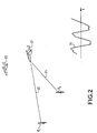
- Figure 2 illustrates a problem with an antenna radar incomplete over a large area.
- This figure shows that for a same target 21, the round trip 22, 23 of a radar signal to this target can be very different from one transmitter or sensor to another.
- the global signal 24 combines the different signals received and in particular the different phase shifts due to the differences in paths 22, 23.
- the different signals received from different transmitters make up the components of the overall signal.
- the combination of delays is different and therefore the global signal 24 is also different. It therefore requires a filtering adapted to each direction, or rather each elementary beam. We saw the number of elementary beams necessary to cover the space, this number can reach or exceed 100,000.
- the appropriate filtering described above must be applied for each of these beams characterizing a direction of sight. This results in computing power very important necessary.
- the processing will have to perform 100,000 linear combinations of the 96 signals received, and therefore reach a few ten times 10 12 operations.
- Figure 3 illustrates in particular the processing steps for signals received carried out by the processing means of a system according to the invention, for the detection of a target.
- a way to reduce the computing power of a consistent processing is to first perform a first step 31 of low resolution processing, reducing the number of dots to calculate and the number of calculations to get each point and then perform in a second step 32 a pre-detection and finally to carry out in a next step 33 processing at full resolution, at least at resolution sufficient, only in areas that produced detection, in fact the zones selected by the pre-detection.
- Conventional radar processing generally involves performing the suitable filter, then perform a detection test on the result.
- this suitable filter is systematically applied to all the cells in the space to be monitored, each cell being characterized by a distance, a Doppler frequency and an angle.
- the means of processing of a radar according to the invention do not perform this processing and accept losses in the first stage 31.
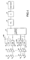
- FIG. 4 illustrates an example of association of the processing means 40 with a reception chain of a radar with a patchy antenna and with beamforming by calculation.
- These processing means 40 implement the preceding steps in association with the reception chain.
- This reception chain comprises Doppler filtering means 47 carrying out FFTs (Fast Fourier Transforms) on the received and digitized signals, means for forming beams by calculation 48 and pulse compression means 49.
- the signals delivered by these pulse compression means are supplied to the processing means 40.
- Each reception module R 1 , ... R N comprises an elementary antenna 44 which supplies the signal to an encoder 46 carrying out a digital conversion of the analog signal.
- the coders 46 thus carry out the sampling and coding of the signals received by the elementary antennas 44.
- the coders 46 are for example synchronized by the same signal 400.
- a receiver 45 consisting of amplifiers, filters and / or demodulators, is for example placed at the antenna outlet. The digitized received signal is transmitted to the Doppler filtering means.
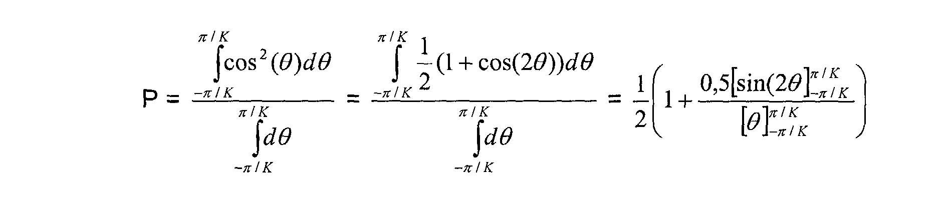
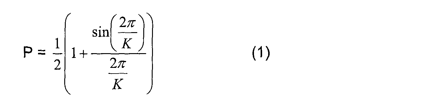
- a non-coherent processing results in a loss compared to the coherent processing, that is to say a reduction in the signal to noise ratio after detection.
- the gain in signal-to-noise ratio S / B is substantially equal to N, conventional value of the gain of a coherent treatment, that is to say of a consistent integration of samples received.
- the invention advantageously uses the fact that when the number of beams formed is very large compared to the number N of sensors, the gain is then reduced to that of a non-coherent integration, ie up to a value of the order of NOT . We can then replace this part of the coherent processing, which is a linear combination of the samples received, by a non-coherent processing, much less greedy in operations, and that for a relatively small loss.
- the number of operations is L.N ' complex multiplications-accumulations, i.e. 4.L.N 'multiplications-accumulations real. Referring to the previous digital application, that makes 24576 real multiplications-accumulations.
- the number of operations is 2.N 'real multiplications and N' real additions to get the squared modules from the two components (real and imaginary) of each sampled signal, N 'square roots to obtain their modules, and N 'additions to obtain the sum of N' modules.
- the quantity in dB is obtained by taking 10 log 10 from expression (1) above, that is:
- the first processing step 31 therefore performs an addition of the modules of the samples, followed in the second step 32 of a comparison to a threshold.
- the first step indeed achieves a part of the coherent processing to obtain a partial signal which results in a resolution lower than the final resolution.
- a third step 33 performs additional processing which is not performed for example only on the signals which gave rise to detection, that is to say whose addition of sampled modules has exceeded the pre-detection threshold of the second step 32.
- This additional step 33 carries therefore on a reduced number of samples: only are treated in this way samples that produced detection. Therefore, this step is less greedy in operations than according to the conventional treatment which makes it apply to all samples.
- the localization processing analyzes the phase of the signals which have produces a detection.
- the filters applied correspond only to areas of space where pre-detection has been observed.
- the localization processing can perform conventional coherent processing on the signals having given rise to detection.
- a radar comprising a device with synthetic emission and beam formation by calculation whose network of patchy antennas is divided into sub-networks, such as illustrated in FIG. 5.
- This antenna thus comprises for example 6 sub-networks reception SR1, ... SR6 each having 16 sensors.
- These subnets are for example linear, i.e. their sensors are aligned.
- These sub-networks can be distributed according to a geometry any. They can be distributed for example in star or in polygon as illustrated in FIG. 5 in a particular case with 6 subnets. This polygon can be regular or not.
- Subnets can be related or disjointed. They can be inscribed in a circle with a diameter of several hundred meters. Only the reception network is represented in Figure 5.
- the transmission network can obviously have a structure similar.
- the transmitters are then divided into P sub-networks, the means processing adding in the first step signals from emissions from each of the broadcast subnets.
- the means of treatment add in the first step 31 signals from the emissions of each of the transmission subnets received in each subnetwork of reception.
- a processing according to the invention performs much fewer operations, all the more since it takes into account in the addition of the first step only 6 signals, at the rate of one signal per sub-network.
- the first step it calculates for example P R beams for each of the sub-networks for example by the means 48 for forming beams by calculation, where P R is the number of sensors per sub-network.
- P R is the number of sensors per sub-network.
- this makes a calculation of 16 beams for each of the 6 subnets. If it is estimated that the calculation of each beam requires 20 operations, that makes 320x6 or about 2000 operations per distance-doppler sample. Then the module calculation is applied to each beam thus calculated. At the rate of approximately 10 operations for a module calculation, to be applied to each of the 16 beams of each of the 6 subnets, approximately 1000 operations per distance-doppler sample are required.
- Non-coherent integration consists in adding the modules thus obtained.
- the operation For each direction of space, the operation consists of select the corresponding beam for each of the 6 sub-networks, and at add the 6 signals thus selected.
- a comparison to the threshold adds one operation per direction, which brings 35,000 operations per doppler distance sample.
- 40,000 10 4 operations per Doppler distance sample, compared to 4.10 7 operations of conventional processing.
- the third step 33 performs the complete calculation only in the directions where there has been detection. We can assume, by taking upper bounds, that there are 1000 targets in the environment and 1000 detections on noise or on parasites, and that each echo requires the processing of 100 distance-doppler samples, in 200 directions. The processing by beam formation by the FFC calculation then requires 2000x100x200x6 complex multiplications / accumulations, or approximately 1.10 10 operations.
- a treatment according to the invention, according to the three steps 31, 32, 33 requires around 10 10 operations and is therefore more than 100 times more economical in operations than a conventional treatment.
- the invention advantageously applies when it is possible to perform a pretreatment, as in the example taken from training radar of beams by calculation comprising an antenna distributed in sub-networks incomplete. This is also the case for coherent doppler processing on several bursts. For example, an average burst has a resolution of 10 m / s and an ambiguous speed of 100 m / s, and the association of 5 gusts gives a resolution of 2 m / s, and removes the ambiguity up to 1000 m / s.
- a processing according to the invention processes each burst with its own resolution, integrates the results in non-coherent, with a possibly lowered threshold, and "zooms" into coherent, that is to say performs a full processing resolution, only in the doppler zones corresponding to detections.
- the invention proposes an addition of the modules. If needed, the processing means perform an addition of module functions some samples. So instead of adding the modules of the samples, they can for example add their squares or other functions.
- the invention has been described for a detection system or method electromagnetic, in particular for a radar. She can nevertheless apply for other types of detection or reception electromagnetic, in particular in the field of telecommunications. It can also be applied for acoustic detection applications, especially in the area of sonars.
Landscapes
- Engineering & Computer Science (AREA)
- Radar, Positioning & Navigation (AREA)
- Remote Sensing (AREA)
- Computer Networks & Wireless Communication (AREA)
- Physics & Mathematics (AREA)
- General Physics & Mathematics (AREA)
- Radar Systems Or Details Thereof (AREA)
Abstract
Description
- La figure 1, une illustration d'un radar à émission synthétique et à formation de faisceau par le calcul selon l'art antérieur, par la disposition de ses modules d'émission et de réception ;
- La figure 2, une illustration d'un signal reçu résultant de la répartition géographique des émetteurs du radar précité ;
- La figure 3, une illustration d'étapes d'un procédé selon l'invention, et du traitement d'un système de détection selon l'invention ;
- La figure 4, une illustration synoptique des moyens de traitements associés à la chaíne de réception d'un radar selon l'invention ;
- La figure 5, un exemple de structure en réseau d'une antenne d'un radar selon l'invention.
- décomposer le signal reçu sur chaque récepteur selon les P composantes émises ;
- appliquer un jeu de NxP phases (une par émetteur et par récepteur), jeu qui dépend de la direction de visée ;
- additionner les NxP signaux ainsi déphasés.

Claims (27)
- Système de détection portant sur N signaux reçus, caractérisé en ce qu'il comporte des moyens de traitement (40) effectuant au moins une première étape (31) d'addition de fonctions des modules des signaux suivie d'une deuxième étape (32) de comparaison de la somme à un seuil donné, une détection correspondant au dépassement du seuil.
- Système selon la revendication 1, caractérisé en ce que la première étape (31) effectue l'addition des modules des signaux.
- Système selon l'une quelconque des revendications 1 ou 2, caractérisé en ce que le seuil est baissé d'au moins d'un niveau correspondant au moins à la perte de traitement non cohérent.
- Système selon l'une quelconque des revendications 1 ou 2, caractérisé en ce que la deuxième étape est suivie d'une étape (33) effectuant un traitement de confirmation de la détection sur les signaux qui ont donné lieu à détection.
- Système selon l'une quelconque des revendications précédentes, caractérisé en ce que la deuxième étape est suivie d'une étape (33) effectuant un traitement de localisation sur les signaux ayant donné lieu à détection.
- Système selon la revendication 5, caractérisé en ce que le traitement de localisation effectue un traitement cohérent des signaux.
- Système selon la revendication 5, caractérisé en ce que le traitement de localisation analyse la phase des signaux.
- Système selon l'une quelconque des revendications précédentes, caractérisé en ce que les signaux sont échantillonnés.
- Système selon l'une quelconque des revendications précédentes, caractérisé en ce qu'il comporte un dispositif à formation de faisceau par le calcul et à antenne en réseau lacunaire.
- Système selon la revendication 9, caractérisé en ce que les capteurs sont répartis en N sous-réseaux (SR1, ....SR6), les moyens de traitement additionnant dans la première étape (31) N signaux reçus chacun d'un sous-réseau.
- Système selon l'une quelconque des revendications précédentes, caractérisé en ce qu'il comporte un dispositif à émission synthétique à réseau d'émission lacunaire.
- Système selon la revendication 11, caractérisé en ce que les émetteurs sont répartis en P sous-réseaux, les moyens de traitement additionnant dans la première étape (31) des signaux issus des émissions de chacun des sous-réseaux émission.
- Système selon les revendications 9 à 12, caractérisé en ce que les moyens de traitement additionnent dans la première étape (31) des signaux issus des émissions de chacun des sous-réseaux émission, reçus dans chaque sous-réseau de réception.
- Système selon les revendications 10 et 12 ou la revendication 13, caractérisé en ce que les sous-réseaux sont linéaires.
- Système selon la revendication 14, caractérisé en ce que les sous-réseaux sont disposés en polygone.
- Système selon l'une quelconque des revendications précédentes, caractérisé en ce qu'il est un système de détection électromagnétique.
- Système selon l'une quelconque des revendications 1 à 15, caractérisé en ce qu'il est un système de détection acoustique.
- Procédé de détection portant sur N signaux reçus, caractérisé en ce qu'il comporte au moins une première étape (31) d'addition de fonctions des modules des signaux suivie d'une deuxième étape (32) de comparaison de la somme à un seuil donné, une détection correspondant au dépassement du seuil.
- Procédé selon la revendication 18, caractérisé en ce que la première étape (31) effectue l'addition des modules des signaux.
- Procédé selon l'une quelconque des revendications 18 ou 19, caractérisé en ce que le seuil est baissé d'au moins d'un niveau correspondant au moins à la perte de traitement non cohérent.
- Procédé selon l'une quelconque des revendications 18 ou 19, caractérisé en ce que la deuxième étape est suivie d'une étape (33) effectuant traitement de confirmation de la détection sur les signaux qui ont donné lieu à détection.
- Procédé selon l'une quelconque des revendications 18 à 21, caractérisé en ce que la deuxième étape est suivie d'une étape (33) effectuant un traitement de localisation sur les signaux ayant donné lieu à détection.
- Procédé selon la revendication 22, caractérisé en ce que le traitement de localisation effectue un traitement cohérent des signaux.
- Procédé selon la revendication 22, caractérisé en ce que le traitement de localisation analyse la phase des signaux.
- Procédé selon l'une quelconque des revendications 18 à 24, caractérisé en ce que les signaux sont échantillonnés.
- Procédé selon l'une quelconque des revendications 18 à 25, caractérisé en ce que la détection est électromagnétique.
- Procédé selon l'une quelconque des revendications 18 à 25, caractérisé en ce que la détection est acoustique.
Applications Claiming Priority (2)
| Application Number | Priority Date | Filing Date | Title |
|---|---|---|---|
| FR0104114 | 2001-03-27 | ||
| FR0104114A FR2822958B1 (fr) | 2001-03-27 | 2001-03-27 | Procede et systeme de detection, notamment radar a reseau d'emission et reception et a formation de faisceau par le calcul |
Publications (1)
| Publication Number | Publication Date |
|---|---|
| EP1245965A1 true EP1245965A1 (fr) | 2002-10-02 |
Family
ID=8861588
Family Applications (1)
| Application Number | Title | Priority Date | Filing Date |
|---|---|---|---|
| EP02290733A Withdrawn EP1245965A1 (fr) | 2001-03-27 | 2002-03-22 | Procédé et système de détection, notamment radar à réseau d'émission et réception et à formation de faisceau par le calcul |
Country Status (2)
| Country | Link |
|---|---|
| EP (1) | EP1245965A1 (fr) |
| FR (1) | FR2822958B1 (fr) |
Families Citing this family (1)
| Publication number | Priority date | Publication date | Assignee | Title |
|---|---|---|---|---|
| US10877151B2 (en) * | 2015-07-31 | 2020-12-29 | Teledyne Instruments, Inc. | Small aperture acoustic velocity sensor |
Citations (5)
| Publication number | Priority date | Publication date | Assignee | Title |
|---|---|---|---|---|
| DE3108594A1 (de) * | 1981-03-06 | 1982-09-23 | Siemens AG, 1000 Berlin und 8000 München | Pulsdoppler-radarempfaenger |
| EP0096144A1 (fr) * | 1982-06-15 | 1983-12-21 | SELENIA INDUSTRIE ELETTRONICHE ASSOCIATE S.p.A. | Système pour éliminer le brouillage intentionnel reçu par un radar à monopulse avec réseau d'antennes à déphasage |
| US5172118A (en) * | 1980-12-29 | 1992-12-15 | Raytheon Company | All weather tactical strike system (AWISS) and method of operation |
| EP0615137A2 (fr) * | 1993-03-09 | 1994-09-14 | Hughes Missile Systems Company | Radar à formation d'images tridimensionelles |
| FR2709835A1 (fr) * | 1987-06-12 | 1995-03-17 | Thomson Csf | Procédé d'extraction de cibles d'un signal radar et radar susceptible de mettre en Óoeuvre ledit procédé. |
-
2001
- 2001-03-27 FR FR0104114A patent/FR2822958B1/fr not_active Expired - Fee Related
-
2002
- 2002-03-22 EP EP02290733A patent/EP1245965A1/fr not_active Withdrawn
Patent Citations (5)
| Publication number | Priority date | Publication date | Assignee | Title |
|---|---|---|---|---|
| US5172118A (en) * | 1980-12-29 | 1992-12-15 | Raytheon Company | All weather tactical strike system (AWISS) and method of operation |
| DE3108594A1 (de) * | 1981-03-06 | 1982-09-23 | Siemens AG, 1000 Berlin und 8000 München | Pulsdoppler-radarempfaenger |
| EP0096144A1 (fr) * | 1982-06-15 | 1983-12-21 | SELENIA INDUSTRIE ELETTRONICHE ASSOCIATE S.p.A. | Système pour éliminer le brouillage intentionnel reçu par un radar à monopulse avec réseau d'antennes à déphasage |
| FR2709835A1 (fr) * | 1987-06-12 | 1995-03-17 | Thomson Csf | Procédé d'extraction de cibles d'un signal radar et radar susceptible de mettre en Óoeuvre ledit procédé. |
| EP0615137A2 (fr) * | 1993-03-09 | 1994-09-14 | Hughes Missile Systems Company | Radar à formation d'images tridimensionelles |
Also Published As
| Publication number | Publication date |
|---|---|
| FR2822958A1 (fr) | 2002-10-04 |
| FR2822958B1 (fr) | 2004-04-09 |
Similar Documents
| Publication | Publication Date | Title |
|---|---|---|
| EP0867731B1 (fr) | Procédé et dispositif de levée d'ambiguité en distance appliquée notamment à un radar à saut de fréquence | |
| EP2831615B1 (fr) | Dispositif de détection électromagnétique actif et passif à faible probabilité d'interception | |
| EP2287633B1 (fr) | Radar de détection de cibles aériennes équipant un aéronef notamment pour l'évitement d'obstacles en vol | |
| EP2762912B1 (fr) | Dispositif et procédé de collecte de données pour la localisation d'une source d'interférence | |
| EP3022573B1 (fr) | Dispositif de detection de signaux electromagnetiques | |
| FR2709835A1 (fr) | Procédé d'extraction de cibles d'un signal radar et radar susceptible de mettre en Óoeuvre ledit procédé. | |
| EP3321711B1 (fr) | Dispositif de reception pour antenne a balayage electronique apte a fonctionner en mode radar et resm, et radar equipe d'un tel dispositif | |
| EP0002642B1 (fr) | Système d'antenne à pouvoir séparateur élevé | |
| EP0752597B1 (fr) | Circuit de traitement polarimétrique de détection pour récepteur radar | |
| FR2998975A1 (fr) | Procede de filtrage, dans un signal radar, des ambiguites distance par codage d'impulsions et traitement multi-voies | |
| WO2022073727A1 (fr) | Radar doppler a balayage electronique ambigu | |
| EP2737337B1 (fr) | Dispositif de detection d'une cible resistant au fouillis | |
| FR2882442A1 (fr) | Procede de detection en mode bi-statique par exploitation passive d'emissions radioelectriques non cooperantes | |
| EP1428038B1 (fr) | Procede de traitement des signaux d'une antenne lineaire remorquee | |
| FR2817973A1 (fr) | Methode de detection et de positionnement d'objets basee sur deux etapes de formation numerique de faisceaux d'un reseau phase de capteurs | |
| EP0580695B1 (fr) | Procede de compensation du mouvement de l'antenne pour un sonar | |
| EP4330722B1 (fr) | Système radar et procédé associé pour optimiser l'élimination de fouillis radar | |
| FR2822958A1 (fr) | Procede et systeme de detection, notamment radar a reseau d'emission et reception et a formation de faisceau par le calcul | |
| EP0044235B1 (fr) | Dispositif de détection de cibles mobiles dans un système radar et radar comportant un tel dispositif | |
| EP1233282B1 (fr) | Système à émission et réception réparties, notamment radar à émission synthétique et à formation de faisceau par le calcul | |
| WO2015128351A1 (fr) | Dispositif radar apte a equiper un systeme de surveillance cotiere, et systeme de surveillance cotiere integrant un tel dispositif | |
| EP1855125B1 (fr) | Procédé de filtrage des signaux de brouillage pour une antenne mobile multivoie | |
| EP0977051A1 (fr) | Procédé de restitution de la sensibilité d'un radar en présence d'une pollution électromagnétique impulsionnelle | |
| FR2805617A1 (fr) | Systeme de reperage acoustique par bouees sous-marines | |
| EP1540371B1 (fr) | Antenne sonar synthetique |
Legal Events
| Date | Code | Title | Description |
|---|---|---|---|
| PUAI | Public reference made under article 153(3) epc to a published international application that has entered the european phase |
Free format text: ORIGINAL CODE: 0009012 |
|
| AK | Designated contracting states |
Kind code of ref document: A1 Designated state(s): AT BE CH CY DE DK ES FI FR GB GR IE IT LI LU MC NL PT SE TR |
|
| AX | Request for extension of the european patent |
Free format text: AL;LT;LV;MK;RO;SI |
|
| 17P | Request for examination filed |
Effective date: 20030319 |
|
| AKX | Designation fees paid |
Designated state(s): DE FR GB IT |
|
| 17Q | First examination report despatched |
Effective date: 20081014 |
|
| GRAP | Despatch of communication of intention to grant a patent |
Free format text: ORIGINAL CODE: EPIDOSNIGR1 |
|
| RIN1 | Information on inventor provided before grant (corrected) |
Inventor name: DESODT, GUY, C/O THALES, INTELL. PROP. |
|
| STAA | Information on the status of an ep patent application or granted ep patent |
Free format text: STATUS: THE APPLICATION IS DEEMED TO BE WITHDRAWN |
|
| 18D | Application deemed to be withdrawn |
Effective date: 20121211 |